EP4144610A1 - Door gap compensator, door gap compensator control system and method, and rail vehicle - Google Patents
Door gap compensator, door gap compensator control system and method, and rail vehicle Download PDFInfo
- Publication number
- EP4144610A1 EP4144610A1 EP21797914.5A EP21797914A EP4144610A1 EP 4144610 A1 EP4144610 A1 EP 4144610A1 EP 21797914 A EP21797914 A EP 21797914A EP 4144610 A1 EP4144610 A1 EP 4144610A1
- Authority
- EP
- European Patent Office
- Prior art keywords
- floor
- air inlet
- door gap
- air
- cylinder
- Prior art date
- Legal status (The legal status is an assumption and is not a legal conclusion. Google has not performed a legal analysis and makes no representation as to the accuracy of the status listed.)
- Pending
Links
Images



Classifications
-
- B—PERFORMING OPERATIONS; TRANSPORTING
- B61—RAILWAYS
- B61D—BODY DETAILS OR KINDS OF RAILWAY VEHICLES
- B61D23/00—Construction of steps for railway vehicles
- B61D23/02—Folding steps for railway vehicles, e.g. hand or mechanically actuated
- B61D23/025—Folding steps for railway vehicles, e.g. hand or mechanically actuated electrically or fluid actuated
Definitions
- the present application relates to the technical field of rail vehicle gap compensation, in particular to a door gap compensator, a system and method for controlling the door gap compensator, and a rail vehicle.
- a door gap compensator is used to compensate a gap between a door and a platform. After stopping a vehicle, a pedal of the door gap compensator extends towards the platform to facilitate passengers to get on and off. The pedal of the door gap compensator is retracted away from the platform when starting, so as not to affect normal driving of the vehicle.
- a traditional door gap compensator has the following shortcomings.
- the present application aims to solve at least one of the problems in traditional technology. Therefore, the present application provides a system for controlling a door gap compensator, which solves the problem that a door gap compensator of a traditional pneumatic structure occupies large space, has a complex structure and low reliability, cannot control a pedal telescopic process, and has a pedal telescopic distance being fixed and unadjustable because of adopting a flipping structure.
- the present application further provides a door gap compensator.
- the present application further provides a method for controlling a door gap compensator.
- the present application further provides a rail vehicle.
- the extension air inlet and the retraction air inlet are respectively provided with a throttle valve, and the throttle valves are signally connected to the controller.
- the cylinder body is further provided with a locked air inlet, the locked air inlet is connected with an air pipeline for connecting to the air supply unit, and the air supply unit is an air supply system of a vehicle itself.
- the air pipeline of the extension air inlet, the air pipeline of the retraction air inlet and the air pipeline of the locked air inlet are respectively provided with a magnetic valve, and the magnetic valves are signally connected to the controller.
- the inductive switch is a magnetic control switch
- a magnetic body of the magnetic control switch is arranged on the piston in the cylinder body
- a pair of moving contacts of the magnetic control switch is arranged by intervals outside the cylinder body, and a spacing between two moving contacts is equal to a preset telescopic distance of the air cylinder, where one of the moving contacts is arranged corresponding to a position where the piston does not extend and the magnetic body is provided.
- the door gap compensator provided by embodiments of the present application includes a floor body, a pedal body, and a system for controlling a door gap compensator described above, where the floor body is configured to be fixedly embedded in an installation gap reserved on a floor in a door area of a vehicle body, the pedal body is slidably connected to a bottom surface of the floor body, and the air cylinder is configured to drive the pedal body to extend or retract horizontally along the floor body.
- a fixed end of the cylinder body is rotatably connected to a back end bottom surface of the floor body through a first pin shaft
- an extended end of the piston is rotatably connected to a front end bottom surface of the pedal body through a second pin shaft
- the first pin shaft is arranged in parallel with the second pin shaft
- axial directions of the first pin shaft and the second pin shaft is perpendicular to a telescopic direction of the piston.
- the floor body is used for fixing an installation gap reserved on the floor in the door area of the vehicle body, a sliding rail and a sliding block are slidably connected between the pedal body and the floor body, the sliding rail is fixed at a bottom surface of the floor body, a side of the sliding block facing the slide rail is provided with a sliding groove, a side of the sliding block away from the sliding groove is fixedly connected to an upper surface of the pedal body, and the sliding groove of the sliding block is clamped outside the sliding rail and is slidably connected to the sliding rail.
- the sliding rail is fixedly connected to the bottom surface of the floor body by a fastening bolt
- the sliding block is fixedly connected to an upper surface of the pedal body by a fastening bolt
- the method for controlling the door gap compensator includes: receiving an extending or retracting signal of the door gap compensator, controlling an air pipeline of an extension air inlet or a retraction air inlet of an air cylinder to supply air for the extension air inlet or the retraction air inlet according to a position of a piston of the air cylinder, and controlling the air cylinder to push a pedal body to extend horizontally along a bottom of a floor body to an open position or retract to a closed position.
- the rail vehicle provided by embodiments of the present application includes a cab and the door gap compensator described above, where the cab is provided with a button to control the system for controlling the door gap compensator, an extension air inlet and a retraction air inlet are respectively connected with an air supply unit of the rail vehicle through an air pipeline.
- the system for controlling the door gap compensator of the embodiment of the present application controls an air intake of the extension air inlet or the retraction air inlet through a controller according to a position of the piston detected by the inductive switch, to control the piston to extend or retract to a specified position, so as to make a cylinder distance controllable, and then realize control of a telescopic distance of the pedal body.
- the control method is simple and has high reliability. Once there is a failure that cannot be extended or retracted , it is easy to find the point of failure and solve it.
- the door gap compensator of the embodiment of the present application adopts a floor body and pedal body formed separately, and integrally installed at the installation gap reserved on a floor in a door area of the vehicle body after being combined with the air cylinder to form an integral embedded structure, which occupies small space, and is convenient to be installed, and has high reliability.
- An upper surface of the floor body after installation has the same height as the floor in a passenger room, and an overall matching degree with the vehicle body is high, which reduces steps at the door and improves passability of passengers or wheelchairs or other equipment, facilitates independent control of the door gap compensator.
- a rail vehicle of the embodiment of the present application has all advantages of the door gap compensator mentioned above by arranging the door gap compensator mentioned above, which will not be not repeat here.
- a sliding rail and a sliding block are slidably connected between the pedal body and the floor body.
- the sliding rail is fixed at a bottom surface of the floor body; a side of the sliding block facing the slide rail is provided with a sliding groove, a side of the sliding block away from the sliding groove is fixedly connected to an upper surface of the pedal body, and the sliding groove of the sliding block is clamped outside the sliding rail and is slidably connected to the sliding rail.
- a sliding joint of the sliding rail and the sliding groove is sealed with balls, and a lubricant is arranged in a sealed channel where the balls are arranged; two sides of the sliding rail along its length direction are constructed as concave surfaces.
- the bottom surface of the floor body is constructed with a pair of straight guide grooves for installing the sliding rail, the shape of a cross section of the straight guide groove is convex with a small upper part and a large lower part, an upper opening groove of the straight guide groove matches the sliding rail, and a lower opening groove of the straight guide groove has a gap with an outside of the sliding block; and the pair of the straight guide grooves are arranged on two sides of the driving mechanism.
- an adjustable gasket is provided or not provided between the sliding block and the pedal body.
- the sliding rail is fixedly connected to the bottom surface of the floor body by a fastening bolts
- the sliding block is fixedly connected to an upper surface of the pedal body by a fastening bolt.
- the floor body and the pedal body are formed by extrusion of an aluminum alloy hollow profile, a hollow cavity is formed in the floor body, and a row of parallelogram holes are spaced at a bottom of the cavity, a screw seat is fixed at a connecting end of the fastening bolt, a shape of the screw seat is a parallelogram matched with the parallelogram hole, and a width of the hollow cavity is matched with a length of the screw seat, the screw seat extends into the hollow cavity along a length direction of the parallelogram hole, and rotates to make two sides of a length of the screw seat abut against two inner walls of a width of the cavity.
- a pair of installation interfaces symmetrical about a central axis of the pedal body is formed on a part of the upper surface of the pedal body used to connect with the floor body, the upper surface of the pedal body is formed with anti-skid stripes avoiding the area where the pair of installation interfaces are located, a front end of an upper surface of the floor body is formed with steps to fit a lower flange of the door body.
- the driving mechanism is an air cylinder
- the air cylinder includes a cylinder body and a piston extending or retracting along the cylinder body, a fixed end of the cylinder body is rotatably connected to a back bottom surface of the floor body through a first pin shaft, and an extended end of the piston is rotatably connected to a front bottom surface of the pedal body through a second pin shaft, the first pin shaft is arranged in parallel with the second pin shaft, and axial directions of the first pin shaft and the second pin shaft are perpendicular to a telescopic direction of the piston.
- the cylinder body is provided with an extension air inlet, a retraction air inlet and a locked air inlet, the extension air inlet, the retraction air inlet and the locked air inlet are respectively connected to an air supply unit of the vehicle body through an air channel.
- At least one of air inlets of the extension air inlet, the retraction air inlet and the locked air inlet is provided with a throttle valve.
- the air cylinder is provided with a magnetic control switch, a magnetic body of the magnetic control switch is arranged on the piston in the cylinder body, a pair of moving contacts of the magnetic control switch is arranged by intervals outside the cylinder body, and a spacing between the pair of moving contacts is equal to a preset telescopic distance of the air cylinder, where one of the moving contacts is arranged corresponding to a position where the piston does not extend and the magnetic body is provided.
- the rail vehicle provided by embodiments of the present application includes a vehicle body and the door gap compensator described above, where a door area floor of the vehicle body reserves an installation gap for installing the door gap compensator, a back end of the floor body is fixedly installed on a beam of the vehicle body and is connected to a floor of the vehicle body, and an upper surface of the floor body is flush with an upper surface of the floor of the vehicle body.
- the installation gap is opened from a door area floor to a boundary beam of the vehicle body, a front end of the floor body is flush with an outer side of the boundary beam, the back end of the floor body is provided with a sealed gasket at a joint of the floor body and the floor of the vehicle body, and the upper surface of the floor body is provided with a floor cloth consistent with a floor cloth laid on the upper surface of the floor of the vehicle body.
- 10 floor body; 11: straight guide groove; 20: pedal body; 30: air cylinder; 31: extension air inlet; 32: retraction air inlet; 33: locked air inlet; 40: first pin shaft; 50 second pin shaft; 60: magnetic control switch; 61: signal cable; 70: sliding rail; 80: sliding block; 90 adjustable gasket; 100: fastening bolt; 110: screw seat; 120: beam; 130: vehicle floor; 140: boundary beam.
- connection to and “connected” shall be understood broadly, for example, it may be either fixedly connected or detachably connected, or can be integrated; it may be either mechanically connected, or electrically connected; it may be either directly connected, or indirectly connected through an intermediate medium; or it may be either a communication between two components.
- connection to and “connected” shall be understood broadly, for example, it may be either fixedly connected or detachably connected, or can be integrated; it may be either mechanically connected, or electrically connected; it may be either directly connected, or indirectly connected through an intermediate medium; or it may be either a communication between two components.
- a first feature is "on” or “under” a second feature can refer to that the first feature is directly contacted with the second feature, or the first feature is indirectly contacted with the second feature through an intermediate medium.
- the first feature is "on”, “above” and “over” the second feature can refer to that the first feature is directly above or obliquely above the second feature, or simply refer to that the level height of the first feature is higher than that of the second feature.
- the first feature is "under”, “below” and “beneath” the second feature can refer to that the first feature is directly below or obliquely below the second feature, or simply refer to that the level height of the first feature is lower than that of the second feature.
- a system for controlling a door gap compensator includes an air cylinder 30, an inductive switch and a controller.
- the air cylinder 30 is used to drive a pedal body 20 to extend or retract horizontally along a bottom surface of a floor body 10.
- the air cylinder 30 includes a cylinder body and a piston that extends or retracts along the cylinder body.
- the cylinder body is provided with an extension air inlet 31 and a retraction air inlet 32.
- the extension air inlet 31 and the retraction air inlet 32 are respectively connected with an air pipeline connected to an air supply unit.
- the inductive switch is arranged on the air cylinder 30 for sensing a position of the piston.
- the piston is in a position not extended or not fully extended or in a fully extended position, the specific position of the piston is detected by the inductive switch, which is convenient to control the air supply time.
- the extension air inlet and the retraction air inlet are respectively provided with a throttle valve to adjust the air intake volume, and the throttle valves are signally connected to the controller.
- the throttle valves are signally connected to the controller.
- the "signally connected” can be either wired or wireless.
- the cylinder block is further provided with a locked air inlet 33, which is connected with an air pipeline for connecting to the air supply unit. That is, the cylinder body is provided with an extension air inlet 31, a retraction air inlet 32 and a locked air inlet 33.
- the extension air inlet 31 is arranged at a back end of the cylinder body, that is, at a back end of the piston, and the retraction air inlet 32 is arranged at a front end of the cylinder body.
- the locked air inlet 33 is arranged at a position of a front cylinder opening where a spring plug is arranged.
- the extension air inlet 31, the retraction air inlet 32 and the locked air inlet 33 are respectively used for connecting to the air supply unit of the vehicle body through an air pipeline, so as to facilitate the air supply unit of the vehicle body itself to supply air for the air cylinder 30, which is convenient to use.
- the piston When air is supplied to the extension air inlet 31, the piston extends; and when air is supplied to the retraction air inlet 32, the piston retracts.
- the locked air inlet 33 safety can be increased.
- the premise of arranging the extended inlet 31 and the retracted inlet 32 to work normally is that the locked air inlet 33 can supply air normally.
- the spring plug can be lifted off, so that the air pipeline is communicated.
- the piston can extend or retract according to specific requirements.
- the locked air inlet 33 When the locked air inlet 33 is out of air, the piston is locked and cannot extend or retract. In an event of an emergency or failure, the air inlet 33 can be directly cut off. The piston stopped in place, and there will not be situation where a passenger steps on the pedal body 20 and the pedal body 20 malfunctions and steps on empty, so as to improve safety.
- the air pipeline of the extension air inlet 31, the air pipeline of the retraction air inlet 32 and the air pipeline of the locked air inlet 33 are respectively provided with a magnetic valve, and the magnetic valves are signally connected to the controller.
- On-off of the magnetic valve corresponds to an on-off of the air pipeline, so that the on-off of the air pipeline can be easily controlled by controlling the magnetic valve. For example, after the vehicle arrives at a station, a cab operates the door gap compensator to extend the button, and the magnetic valve on the air pipeline connecting the extension air inlet 31 is opened.
- the air pipeline receives a wind pressure signal
- the air pipeline connected to the extension air inlet 31 of the air cylinder is open, and the piston extends to realize the extending of the pedal body of the door gap compensator.
- the cab operates the door gap compensator retract button, and the corresponding magnetic valve opens.
- the air pipeline corresponding to the retraction air inlet receives the wind pressure signal, and the air pipeline connected to the retraction air inlet opens.
- the piston of the air cylinder retracts to realize the retraction of the pedal body of the door gap compensator.
- the inductive switch is a magnetic control switch 60.
- the magnetic control switch 60 receives the corresponding signal and can provide the specific position of the piston of the air cylinder 30 to the vehicle.
- the vehicle can control air supply of the three air inlets of the cylinder 30 through the position of the piston to realize telescopic control of the pedal body 20.
- the magnetic switch 60 includes a magnetic body (such as a magnet) and a moving contact that interacts with the magnetic body.
- the magnetic body of the magnetic switch 60 is arranged on the piston in the cylinder body, and a pair of moving contacts of the magnetic switch 60 is arranged by intervals outside the cylinder body.
- control system controls the piston to stop working, thereby ensuring the safety of personnel above the pedal body 20.
- the air cylinder 30 includes a cylinder body and a piston that extends or retracts along the cylinder body.
- a fixed end of the cylinder body is rotatably connected to a back end bottom surface of a floor body 10 through a first pin shaft 40.
- An extended end of the piston is rotatably connected to a front end bottom surface of the pedal body 20 through a second pin shaft 50.
- the back end bottom surface of the floor body 10 and the front end bottom surface of the pedal body 20 form a mounting base.
- the first pin shaft 40 and the second pin shaft 50 respectively pass through a rotatable connecting hole of the mounting base and corresponding pin holes to install the air cylinder 30.
- an end of the air cylinder 30 is connected to the floor body 10 and another end of the air cylinder 30 is connected to the pedal body 20.
- the first pin shaft 40 and the second pin shaft 50 are parallel and horizontally arranged, and axial directions of the first pin shaft 40 and the second pin shaft 50 is perpendicular to a telescopic direction of the piston, so that the pedal body 20 has an ability to rotate along a vertical plane.
- the air cylinder 30 can rotate along the pin shaft without generating internal stress.
- the door gap compensator of an embodiment of the present application includes a floor body 10 and a pedal body 20 and the system for controlling the door gap compensator mentioned above.
- the floor body 10 is configured to be fixedly embedded in an installation gap reserved on a floor in a door area of a vehicle body.
- the shape of the floor body 10 can be square or rectangular, and an installation gap is square or rectangular adapted to the size and shape of the floor body 10, so that the floor body 10 can be better matched with the floor in the door area of the vehicle body after installation.
- the pedal body 20 is slidably connected to a bottom surface of the floor body 10. n an embodiment, the pedal body 20 can slide in a straight line along the floor body 10 in a direction pointing to the train platform.
- This embodiment stipulates that a “a front end of the floor body 10" and a “a front end of the pedal body 20" are ends near the platform, and a “a back end of the floor body 10" and a “a back end of the pedal body 20" are ends away from the platform.
- the door gap compensator of the embodiment is embedded in the installation gap as an independent whole, which occupies small space, and is convenient to be installed, and has high reliability.
- An upper surface of the floor body 10 after installation has the same height as the floor in a passenger room, and an overall matching degree with the vehicle body is high, which reduces steps at the door and improves passability of passengers or wheelchairs or other equipment, facilitates independent control of the door gap compensator.
- a sliding rail 70 and a sliding block 80 are slidably connected between the pedal body 20 and the floor body 10.
- the sliding block 80 slides along the sliding rail 70.
- the sliding rail 70 is fixed at a bottom surface of the floor body 10, and the specific fixation method can be fixed by fastener fixed connection or other fixed connection forms.
- a side of the sliding block 80 facing the sliding rail 70 is provided with a sliding groove, and a side of the sliding block 80 away from the sliding groove is fixedly connected to an upper surface of the pedal body 20.
- the specific fixation method can be fixed by fastener fixed connection or other fixed connection forms.
- the sliding groove of the slider 80 is clamped outside the sliding rail 70 and is slidably connected to the slide rail 70.
- the sliding groove can wrap the middle and lower parts of the sliding block 80, so that after the sliding block 80 is installed, there is a certain gap between the sliding block 80 and the bottom surface of the floor body 10, so as to avoid friction between the sliding block 80 and the floor body 10 during sliding.
- a sliding joint of the sliding rail 70 and the sliding groove is sealed with balls, and a lubricant is arranged in a sealed channel where the balls are arranged.
- the contact between the sliding rail 70 and the sliding block 80 is carried out by the balls.
- the sliding block 80 moves on the sliding rail 70, it is rolling friction, and has small resistance.
- the pedal body 20 extends and retracts, it does not have a large lateral displacement, which improves the stability of the door gap compensator.
- the balls in a sealed channel through the lubricant self-lubricating reduce maintenance cycles, and the lubricant can be lubricating oil or grease.
- one row or two rows of balls can be arranged at the connection between the sliding rail 70 and the sliding block 80.
- grooves for installing the balls are arranged at relative positions of the sliding rail 70 and the sliding block 80 respectively.
- the length direction of the grooves is along a sliding direction, and the two grooves form a sealed channel.
- Half of the balls are located in the grooves of the sliding rail 70, and another half of the balls is located in the grooves of the sliding block 80.
- the sliding rail 70 and the sliding block 80 are connected to each other. Through sealed treatment, the loss of lubricant can be avoided to reduce the frequency of increasing lubricant, and impurities such as dust can be prevented from entering the connection between sliding rail 70 and sliding block 80.
- two sides of the sliding rail 70 along its length direction are constructed as concave surfaces, and there is a gap between an inner wall of the sliding groove at the concave surface and the sliding rail 70.
- the bottom surface of the floor body 10 is constructed with a pair of straight guide grooves 11 for installing the sliding rail 70.
- the shape of a cross section of the straight guide groove 11 is convex with a small upper part and a large lower part, that is, an opening of a lower opening groove of the straight guide groove 11 is larger than that of an upper opening groove, and the lower opening groove is connected to the upper opening groove.
- An upper opening groove of the straight guide groove 11 matches the sliding rail 70, and a lower opening groove of the straight guide groove 11 has a gap outside the sliding block 80.
- the sliding block 70 is directly clamped into the upper opening groove and the upper opening groove with interference fit during an installation of the sliding rail 70 without adjusting the orientation of the sliding block rail 70.
- the installation is convenient and the positioning effect is good.
- the sliding rail 70 is stable and reliable after installation.
- a pair of straight guide grooves 11 are arranged in parallel, so that a pair of sliding rails 70 is also parallel to each other after installing.
- a pair of the straight guide grooves 11 are arranged on two sides of the air cylinder.
- the air cylinder can be in the middle of the door gap compensator.
- the pair of the straight guide grooves 11 can be symmetrically arranged corresponding to the air cylinder, so that the sliding of the pedal body 20 is more stable.
- an adjustable gasket 90 is provided or not provided between the sliding block 80 and the pedal body 20, that is, when the spacing between the pedal body 20 and the floor body 10 does not need to be adjusted, an adjustable gasket 90 can be not installed; and when the spacing between the pedal body 20 and the floor body 10 needs to be adjusted, the height difference between the pedal body 20 and the floor body 10 can be adjusted by increasing or decreasing the adjustable gasket 90 between the pedal body 20 and the sliding block 80 during the installation of the sliding block 80.
- the height difference between the pedal body 20 and the floor body 10 is a sum of a thickness of the floor body 10 and a gap between the pedal body 20 and the floor body 10.
- the thickness of the floor body 10 itself is small, and the gap between the pedal body 20 and the floor body 10 is adjustable, so that the height difference between the pedal body 20 and the floor body 10 is small, which can meet the needs of getting on and off special equipment (such as wheelchairs).
- the sliding rail 70 is fixedly connected to the bottom surface of the floor body 10 by a fastening bolt 100
- the sliding block 80 is fixedly connected to an upper surface of the pedal body 20 by a fastening bolt 100 to ensure connection strength and reliability.
- the floor body 10 and the pedal body 20 are formed by extrusion of an aluminum alloy hollow profile, which has high strength, light weight, good forming effect, and various required interfaces can be formed at one time.
- a hollow cavity is formed in the floor body 10, and a row of parallelogram holes are spaced at a bottom of the cavity.
- the length direction of the parallelogram holes can be along a length direction of the hollow cavity.
- a screw base 110 is fixed at a connecting end (an end away from the head of the fastening bolt 100) of the fastening bolts 100.
- the shape of the screw seat 110 is a parallelogram matched with the parallelogram hole, and the width of the hollow cavity is matched with the length of the screw seat 110.
- the screw seat 110 extends into the hollow cavity along the length direction of the parallelogram hole, and rotates at a certain angle to make two sides of a length of the screw seat 110 abut against two inner walls of a width of the cavity, thereby clamping the screw seat 110 in the hollow cavity to ensure stability and firmness of the fastening bolts 100 after installing.
- the shape of the screw seat 110 can also be elliptical, which can also achieve the same function.
- the specific arrangement number of the fastening bolts 100 can be selected according to actual needs.
- the fastening bolts 100 adopting this connection form can realize rapid disassembly and convenient replacement.
- a plurality of through holes for the fastening bolt 100 to pass through are arranged on the sliding rail 70 along its length direction.
- the through holes can be arranged as counterbores, and the heads of the fastening bolts 100 is located in the counterbores.
- a part of the upper surface of the pedal body 20 used to connect with the floor body is formed with a pair of installation interfaces symmetrical about a central axis of the pedal body 20.
- the sliding block 80 is installed in the installation interface, and is fixedly connected to the pedal body 20 through the fastening bolt 100.
- the upper surface of the pedal body 20 is formed with anti-skid stripes avoiding the area where the pair of installation interfaces are located, which can increase anti-slip effect and avoid slipping.
- a front end of an upper surface of the floor body 10 is formed with steps to fit a lower flange of the door body. Therefore, after the door is closed, the lower flange of the door body fits the steps. The sealed effect is increased, and installation space is reserved for the lower flange. After the lower flange fits the steps, an outer side of the lower flange is flush with a front end of the floor body 10.
- a method for controlling a door gap compensator of an embodiment of the present application when a signal that the door gap compensator extends or retracts is received, for example, after the vehicle arrives at a station, the cab operates the door gap compensator to extend the button, the system for controlling the door gap compensator receives the signal that the door gap compensator extends, the magnetic valve on the air pipeline connected to the extension air inlet is opened, the air pipeline receives a wind pressure signal, and the air pipeline connected to the extension air inlet of the air cylinder is opened, and the piston extending achieves the pedal body of the door gap compensator extending.
- the driver's cab operates the door gap compensator to retract the bottom.
- the system for controlling the door gap compensate receives a retract signal of the door gap compensator, and the corresponding magnetic valve opens, and the air pipeline corresponding to the retraction air inlet receives the air pressure signal.
- the air pipeline connected to the retraction air inlet opens, and the piston of the pneumatic retracts to realize a retraction of the pedal body of the door gap compensator.
- the controller controls the air pipeline of the extension air inlet or retraction air inlet to supply air to the extension air inlet or retraction air inlet, and controls the air cylinder to push the pedal body to extend horizontally along the bottom surface of the floor body to an opening position or to retract to a closing position.
- the opening position means that the pedal body extends to a maximum distance
- the closing position means that the pedal body retracts to a position in the vehicle body that does not occupy the space outside the vehicle.
- the rail vehicle provided by embodiments of the present application includes a cab and the door gap compensator described above.
- the cab is provided with a button to control the system for controlling the door gap compensator.
- it can be provided with an extension button to control an extension of the extension air inlet and a retraction button to control a retraction of the retraction air inlet.
- the extension air inlet and the retraction air inlet are respectively connected with an air supply unit of the rail vehicle through air pipelines.
- the air supply unit of the vehicle itself is used for air supply without providing with other air supply units, which is convenient to arrange and simple to operate.
- a door area of this embodiment reserves an installation gap for installing the door gap compensator.
- a back end of the floor body 10 is fixedly installed on a beam 120 of the vehicle body and is connected to a floor of the vehicle body.
- the beam 120 of the vehicle body bears the door gap compensator, which has strong bearing capacity and high reliability.
- the upper surface of the floor body 10 being flush with the upper surface of the floor of the vehicle body makes the door gap compensator better matched with the vehicle after installation, reduces the steps at the door and improves the passability.
- the working principle of the door gap compensator is that when the piston of the air cylinder 30 extends, the pedal body 20 is pushed to extend to make up for a gap between the vehicle and the platform, and the piston is locked in an extending position after it is in place.
- the air cylinder 30 piston retracts, the pedal body 20 is pulled back, hidden under the floor body 10, consistent with the outer contour of the car body, and will not invade a limit.
- the locked air inlet 33 closes an air pressure, the piston of the air cylinder 30 is in a locked position, which cannot extend or retract to ensure safety.
- the door gap compensator of the embodiment is embedded in the installation gap as an independent whole, which has small space occupation, is convenient to install and has high reliability.
- the upper surface of the floor body 10 after installation has the same as the height of the floor in a passenger room, and an overall matching degree with the vehicle body is high, which reduces the steps at the door and improves the passability of passengers or wheelchairs or other equipment. It is convenient for independent control of the system for controlling the door gap compensator.
- the installation gap is opened from a door area floor to a boundary beam 140 of the vehicle body, a front end of the floor body 10 is flush with an outer side of the boundary beam 140, and does not occupy the space inside the vehicle after installation.
- the back end of the floor body 10 is provided with a sealed gasket at a joint of the floor body and the floor of the vehicle body, which has good sealed performance.
- the upper surface of the floor body 10 is provided with a floor cloth consistent with a floor cloth laid on the upper surface of the floor of the vehicle body, thus the door gap compensator is integrated with a vehicle body floor 130, which has high matching degree.
- a door gap compensator including a floor body 10, a pedal body 20 and a driving mechanism.
- the floor body 10 is configured to be fixedly embedded in an installation gap reserved on a floor in a door area of a vehicle body.
- the shape of the floor body 10 can be square or rectangular, and the installation gap is square or rectangular matched the size and shape of the floor body 10, so that the floor body 10 can be better matched with the floor in the door area of the car body after installation.
- the pedal body 20 is slidably connected to the bottom surface of the floor body 10.
- the pedal body 20 can slide in a straight line along the floor body 10 in the direction pointing to the train platform.
- This embodiment stipulates that a “a front end of the floor body 10" and a “a front end of the pedal body 20" are ends near the platform, and a “a back end of the floor body 10" and a “a back end of the pedal body 20" are ends away from the platform.
- the driving mechanism is configured to drive the pedal body 20 to extend or retract horizontally along the floor body 10, and telescopic mode is highly reliable.
- the air cylinder 30 provides power for a straight sliding of the pedal body 20, so that when the pedal body 20 needs to be extended, the air cylinder 30 provides the power to extend, and the drive the pedal body 20 to extend. When the pedal body 20 needs to be retracted, the air cylinder 30 provides the power to retract, and drive the pedal body 20 to retract.
- the door gap compensator of the embodiment is embedded in the installation gap as an independent whole, which occupies small space, and is convenient to be installed, and has high reliability.
- An upper surface of the floor body 10 after installation has the same height as the floor in a passenger room, and an overall matching degree with the vehicle body is high, which reduces steps at the door and improves passability of passengers or wheelchairs or other equipment, facilitates independent control of the door gap compensator.
- a sliding rail 70 and a sliding block 80 are slidably connected between the pedal body 20 and the floor body 10.
- the sliding block 80 slides along the sliding rail 70.
- the sliding rail 70 is fixed at a bottom surface of the floor body 10, and the specific fixation method can be fixed by fastener fixed connection or other fixed connection forms.
- a side of the sliding block 80 facing the sliding rail 70 is provided with a sliding groove, and a side of the sliding block 80 away from the sliding groove is fixedly connected to an upper surface of the pedal body 20.
- the specific fixation method can be fixed by fastener fixed connection or other fixed connection forms.
- the sliding groove of the slider 80 is clamped outside the sliding rail 70 and is slidably connected to the slide rail 70.
- the sliding groove can wrap the middle and lower parts of the sliding block 80, so that after the sliding block 80 is installed, there is a certain gap between the sliding block 80 and the bottom surface of the floor body 10, so as to avoid friction between the sliding block 80 and the floor body 10 during sliding.
- a sliding joint of the sliding rail 70 and the sliding groove is sealed with balls, and a lubricant is arranged in a sealed channel where the balls are arranged.
- the contact between the sliding rail 70 and the sliding block 80 is carried out by the balls.
- the sliding block 80 moves on the sliding rail 70, it is rolling friction, and has small resistance.
- the pedal body 20 extends and retracts, it does not have a large lateral displacement, which improves the stability of the door gap compensator.
- the balls in a sealed channel through the lubricant self-lubricating reduce maintenance cycles, and the lubricant can be lubricating oil or grease.
- one row or two rows of balls can be arranged at the connection between the sliding rail 70 and the sliding block 80.
- grooves for installing the balls are arranged at relative positions of the sliding rail 70 and the sliding block 80 respectively.
- the length direction of the grooves is along a sliding direction, and the two grooves form a sealed channel.
- Half of the balls are located in the grooves of the sliding rail 70, and another half of the balls is located in the grooves of the sliding block 80.
- the sliding rail 70 and the sliding block 80 are connected to each other. Through sealed treatment, the loss of lubricant can be avoided to reduce the frequency of increasing lubricant, and impurities such as dust can be prevented from entering the connection between sliding rail 70 and sliding block 80.
- two sides of the sliding rail 70 along its length direction are constructed as concave surfaces, and there is a gap between an inner wall of the sliding groove at the concave surface and the sliding rail 70.
- the bottom surface of the floor body 10 is constructed with a pair of straight guide grooves 11 for installing the sliding rail 70.
- the shape of a cross section of the straight guide groove 11 is convex with a small upper part and a large lower part, that is, an opening of a lower opening groove of the straight guide groove 11 is larger than that of an upper opening groove, and the lower opening groove is connected to the upper opening groove.
- An upper opening groove of the straight guide groove 11 matches the sliding rail 70, and a lower opening groove of the straight guide groove 11 has a gap outside the sliding block 80.
- the sliding block 70 is directly clamped into the upper opening groove and the upper opening groove with interference fit during an installation of the sliding rail 70 without adjusting the orientation of the sliding block rail 70.
- the installation is convenient and the positioning effect is good.
- the sliding rail 70 is stable and reliable after installation.
- a pair of straight guide grooves 11 are arranged in parallel, so that a pair of sliding rails 70 is also parallel to each other after installing.
- a pair of the straight guide grooves 11 are arranged on two sides of the driving mechanism.
- the driving mechanism can be in the middle of the door gap compensator.
- the pair of the straight guide grooves 11 can be symmetrically arranged corresponding to the driving mechanism, so that the sliding of the pedal body 20 is more stable.
- an adjustable gasket 90 is provided or not provided between the sliding block 80 and the pedal body 20, that is, when the spacing between the pedal body 20 and the floor body 10 does not need to be adjusted, an adjustable gasket 90 can be not installed; and when the spacing between the pedal body 20 and the floor body 10 needs to be adjusted, the height difference between the pedal body 20 and the floor body 10 can be adjusted by increasing or decreasing the adjustable gasket 90 between the pedal body 20 and the sliding block 80 during the installation of the sliding block 80.
- the height difference between the pedal body 20 and the floor body 10 is a sum of a thickness of the floor body 10 and a gap between the pedal body 20 and the floor body 10.
- the thickness of the floor body 10 itself is small, and the gap between the pedal body 20 and the floor body 10 is adjustable, so that the height difference between the pedal body 20 and the floor body 10 is small, which can meet the needs of getting on and off special equipment (such as wheelchairs).
- the sliding rail 70 is fixedly connected to the bottom surface of the floor body 10 by a fastening bolt 100
- the sliding block 80 is fixedly connected to an upper surface of the pedal body 20 by a fastening bolt 100 to ensure connection strength and reliability.
- the screw seat 110 extends into the hollow cavity along the length direction of the parallelogram hole, and rotates at a certain angle to make two sides of length of the screw seat 110 abut against two inner walls of a width of the cavity, thereby clamping the screw seat 110 in the hollow cavity to ensure stability and firmness of the fastening bolts 100 after installing.
- the shape of the screw seat 110 can also be elliptical, which can also achieve the same function.
- the specific arrangement number of the fastening bolts 100 can be selected according to actual needs.
- the fastening bolts 100 adopting this connection form can realize rapid disassembly and convenient replacement.
- a plurality of through holes for the fastening bolt 100 to pass through are arranged on the sliding rail 70 along its length direction.
- the through holes can be arranged as counterbore, and the heads of the fastening bolts 100 is located in the counterbore.
- a part of the upper surface of the pedal body 20 used to connect with the floor body is formed with a pair of installation interfaces symmetrical about a central axis of the pedal body 20.
- the sliding block 80 is installed in the installation interface, and is fixedly connected to the pedal body 20 through the fastening bolts 100.
- the upper surface of the pedal body 20 is formed with anti-skid stripes avoiding the area where the pair of installation interfaces are located, which can increase anti-slip effect and avoid slipping.
- a front end of an upper surface of the floor body 10 is formed with steps to fit a lower flange of the door body. Therefore, after the door is closed, the lower flange of the door body fits the steps. The sealed effect is increased and installation space is reserved for the lower flange. After the lower flange fits the steps, an outer side of the lower flange is flush with a front end of the floor body 10.
- the driving mechanism is an air cylinder 30.
- Parallel pin holes are arranged at two ends of the air cylinder 30, and the pin holes are arranged horizontally.
- the air cylinder 30 includes a cylinder body and a piston that extends or retracts along the cylinder body.
- a fixed end of the cylinder body is rotatably connected to a back end bottom surface of a floor body 10 through a first pin shaft 40.
- An extended end of the piston is rotatably connected to a front end bottom surface of the pedal body 20 through a second pin shaft 50.
- the back end bottom surface of the floor body 10 and the front end bottom surface of the pedal body 20 form a mounting base.
- the first pin shaft 40 and the second pin shaft 50 respectively pass through a rotatable connecting hole of the mounting base and corresponding pin holes to install the air cylinder 30.
- an end of the air cylinder 30 is connected to the floor body 10 and another end of the air cylinder 30 is connected to the pedal body 20.
- the first pin shaft 40 and the second pin shaft 50 are parallel and horizontally arranged, and axial directions of the first pin shaft 40 and the second pin shaft 50 is perpendicular to a telescopic direction of the piston, so that the pedal body 20 has an ability to rotate along a vertical plane.
- the air cylinder 30 can rotate along the pin shaft without generating internal stress.
- the cylinder body is provided with an extension air inlet 31, a retraction air inlet 32 and a locked air inlet 33.
- the extension air inlet 31 is arranged at a back end of the cylinder body, that is at a back end of the piston, and the retraction air inlet 32 is arranged at a front end of the cylinder body.
- the locked air inlet 33 is arranged at a position of a front cylinder opening where a spring plug is arranged.
- the extension air inlet 31, the retraction air inlet 32 and the locked air inlet 33 are respectively used for connecting to the air supply unit of the vehicle body through an air channel, so as to facilitate the air supply unit of the vehicle body itself to supply air for the air cylinder 30, which is convenient to use.
- a throttle valve is arranged on at least one of the inlets of the extension air inlet 31, the retraction air inlet 32 and the locked air inlet 33.
- a throttle valve can be arranged in the extension air inlet 31, the retraction air inlet 32 and the locked air inlet, or a throttle valve can be arranged at one or two of the inlets. The specific arrangement can be selected as needed. By arranging the throttle valve, the telescopic speed of the piston can be adjusted.
- the cylinder 30 is provided with a magnetic control switch 60.
- the magnetic control switch 60 receives the corresponding signal, and can provide the specific position of the cylinder 30 piston to the vehicle.
- the vehicle controls the air supply volume of the three air inlets of the cylinder 30 through the position of the piston, and realizes telescopic control of the pedal body 20 of the door gap compensator.
- the magnetic switch 60 includes a magnetic body (such as a magnet) and a moving contact that interacts with the magnetic body.
- the magnetic body of the magnetic switch 60 is arranged on the piston in the cylinder body, and a pair of moving contacts of the magnetic switch 60 is arranged by intervals outside the cylinder body.
- a spacing between two moving contacts is equal to a preset telescopic distance of the air cylinder 30.
- One of the moving contacts is arranged corresponding to a position where the piston does not extend and the magnetic body is provided.
- Another moving contact is arranged and spaced by a telescopic distance near a front end of the cylinder body.
- a position where the piston does not extend is triggered by the magnetic body to generate a signal and send it to a vehicle control system.
- this moving contact is triggered to generate a signal and send it to the vehicle control system, and the control system controls the piston to stop at position of the corresponding distance.
- control system controls the piston to stop working thereby ensuring the safety of the personnel above the pedal body 20.
- a rail vehicle includes a vehicle body and the door gap compensator mentioned above.
- a door area floor of the vehicle body reserves an installation gap for installing the door gap compensator.
- a back end of the floor body 10 is fixedly installed on a beam 120 of the vehicle body and is connected to a floor of the vehicle body.
- the beam 120 of the vehicle body bears the door gap compensator, which has strong bearing capacity and high reliability.
- the upper surface of the floor body 10 being flush with an upper surface of the floor of the vehicle body makes the door gap compensator better matched with the vehicle after installation, reduces the steps at the door and improves the passability.
- the working principle of the door gap compensator is that when the piston of the air cylinder 30 extends, the pedal body 20 is pushed to extend to make up for a gap between the vehicle and the platform, and the piston is locked in an extending position after it is in place.
- the air cylinder 30 piston retracts, the pedal body 20 is pulled back, hidden under the floor body 10, consistent with the outer contour of the car body, and will not invade a limit.
- the locked air inlet 33 closes an air pressure, the piston of the air cylinder 30 is in a locked position, which cannot extend or retract to ensure safety.
- the door gap compensator of the embodiment is embedded in the installation gap as an independent whole, which has small occupation, is convenient to install and has high reliability.
- the upper surface of the floor body 10 after installation has the same as the height of the floor in a passenger room, and an overall matching degree with the vehicle body is high, which reduces the steps at the door and improves the passability of passengers or wheelchairs or other equipment. It is convenient for independent control of the system for controlling door gap compensators.
Landscapes
- Engineering & Computer Science (AREA)
- Mechanical Engineering (AREA)
- Seats For Vehicles (AREA)
- Platform Screen Doors And Railroad Systems (AREA)
Abstract
Description
- The present application claims priority to
Chinese Applications No. 202010346449.9, filed on April 27, 2020 No. 202010345747.6, filed on April 27, 2020 - The present application relates to the technical field of rail vehicle gap compensation, in particular to a door gap compensator, a system and method for controlling the door gap compensator, and a rail vehicle.
- A door gap compensator, as the name suggests, is used to compensate a gap between a door and a platform. After stopping a vehicle, a pedal of the door gap compensator extends towards the platform to facilitate passengers to get on and off. The pedal of the door gap compensator is retracted away from the platform when starting, so as not to affect normal driving of the vehicle.
- However, a traditional door gap compensator has the following shortcomings.
- (1) The traditional door gap compensator with a pneumatic structure adopts a flipping structure, which occupies large space, has a complex structure and has low reliability.
- (2) A traditional pneumatic push structure cannot realize the control of a pedal telescopic process, and a pedal telescopic distance is fixed and not adjustable.
- (3) The traditional pneumatic push structure cannot realize a control of telescopic force for pushing a cylinder.
- (4) A gap between floor and a pedal of a traditional structure is large, which cannot meet the requirements of free boarding and alighting of special equipment such as wheelchairs, and cannot adjust the gap between the floor and the pedal.
- The present application aims to solve at least one of the problems in traditional technology. Therefore, the present application provides a system for controlling a door gap compensator, which solves the problem that a door gap compensator of a traditional pneumatic structure occupies large space, has a complex structure and low reliability, cannot control a pedal telescopic process, and has a pedal telescopic distance being fixed and unadjustable because of adopting a flipping structure.
- The present application further provides a door gap compensator.
- The present application further provides a method for controlling a door gap compensator.
- The present application further provides a rail vehicle.
- The system for controlling the door gap compensator provided by embodiments of the present application includes:
- an air cylinder, used to drive a pedal body to extend or retract horizontally along a bottom surface of a floor body, where the air cylinder includes a cylinder body and a piston extending or retracting along the cylinder body, the cylinder body is provided with an extension air inlet and a retraction air inlet, and the extension air inlet and the retraction air inlet are respectively connected with an air pipeline connected to an air supply unit;
- an inductive switch, arranged on the air cylinder for sensing a position of the piston; and
- a controller, used to control the extension air inlet or the retraction air inlet to intake air according to a position of the piston detected by the inductive switch, so as to control the piston to extend or retract to a specified position.
- According to an embodiment of the present application, the extension air inlet and the retraction air inlet are respectively provided with a throttle valve, and the throttle valves are signally connected to the controller.
- According to an embodiment of the present application, the cylinder body is further provided with a locked air inlet, the locked air inlet is connected with an air pipeline for connecting to the air supply unit, and the air supply unit is an air supply system of a vehicle itself.
- According to an embodiment of the present application, the air pipeline of the extension air inlet, the air pipeline of the retraction air inlet and the air pipeline of the locked air inlet are respectively provided with a magnetic valve, and the magnetic valves are signally connected to the controller.
- According to an embodiment of the present application, the inductive switch is a magnetic control switch, a magnetic body of the magnetic control switch is arranged on the piston in the cylinder body, a pair of moving contacts of the magnetic control switch is arranged by intervals outside the cylinder body, and a spacing between two moving contacts is equal to a preset telescopic distance of the air cylinder, where one of the moving contacts is arranged corresponding to a position where the piston does not extend and the magnetic body is provided.
- The door gap compensator provided by embodiments of the present application includes a floor body, a pedal body, and a system for controlling a door gap compensator described above, where the floor body is configured to be fixedly embedded in an installation gap reserved on a floor in a door area of a vehicle body, the pedal body is slidably connected to a bottom surface of the floor body, and the air cylinder is configured to drive the pedal body to extend or retract horizontally along the floor body.
- According to an embodiment of the present application, a fixed end of the cylinder body is rotatably connected to a back end bottom surface of the floor body through a first pin shaft, an extended end of the piston is rotatably connected to a front end bottom surface of the pedal body through a second pin shaft, the first pin shaft is arranged in parallel with the second pin shaft, and axial directions of the first pin shaft and the second pin shaft is perpendicular to a telescopic direction of the piston.
- According to an embodiment of the present application, the floor body is used for fixing an installation gap reserved on the floor in the door area of the vehicle body, a sliding rail and a sliding block are slidably connected between the pedal body and the floor body, the sliding rail is fixed at a bottom surface of the floor body, a side of the sliding block facing the slide rail is provided with a sliding groove, a side of the sliding block away from the sliding groove is fixedly connected to an upper surface of the pedal body, and the sliding groove of the sliding block is clamped outside the sliding rail and is slidably connected to the sliding rail.
- According to an embodiment of the present application, the sliding rail is fixedly connected to the bottom surface of the floor body by a fastening bolt, and the sliding block is fixedly connected to an upper surface of the pedal body by a fastening bolt.
- The method for controlling the door gap compensator provided by embodiments of the present application includes: receiving an extending or retracting signal of the door gap compensator, controlling an air pipeline of an extension air inlet or a retraction air inlet of an air cylinder to supply air for the extension air inlet or the retraction air inlet according to a position of a piston of the air cylinder, and controlling the air cylinder to push a pedal body to extend horizontally along a bottom of a floor body to an open position or retract to a closed position.
- The rail vehicle provided by embodiments of the present application includes a cab and the door gap compensator described above, where the cab is provided with a button to control the system for controlling the door gap compensator, an extension air inlet and a retraction air inlet are respectively connected with an air supply unit of the rail vehicle through an air pipeline.
- The solutions described above of the embodiments of the present application have at least one of the following effects.
- The system for controlling the door gap compensator of the embodiment of the present application, controls an air intake of the extension air inlet or the retraction air inlet through a controller according to a position of the piston detected by the inductive switch, to control the piston to extend or retract to a specified position, so as to make a cylinder distance controllable, and then realize control of a telescopic distance of the pedal body. The control method is simple and has high reliability. Once there is a failure that cannot be extended or retracted , it is easy to find the point of failure and solve it.
- The door gap compensator of the embodiment of the present application adopts a floor body and pedal body formed separately, and integrally installed at the installation gap reserved on a floor in a door area of the vehicle body after being combined with the air cylinder to form an integral embedded structure, which occupies small space, and is convenient to be installed, and has high reliability. An upper surface of the floor body after installation has the same height as the floor in a passenger room, and an overall matching degree with the vehicle body is high, which reduces steps at the door and improves passability of passengers or wheelchairs or other equipment, facilitates independent control of the door gap compensator.
- A rail vehicle of the embodiment of the present application has all advantages of the door gap compensator mentioned above by arranging the door gap compensator mentioned above, which will not be not repeat here.
- The door gap compensator provided by embodiments of the present application includes:
- a floor body, configured to be fixedly embedded in an installation gap reserved on a floor in a door area of a vehicle body;
- a pedal body, slidably connected to a bottom surface of the floor body; and
- a driving mechanism, configured to drive the pedal body to extend or retract horizontally along the floor body.
- According to an embodiment of the present application, a sliding rail and a sliding block are slidably connected between the pedal body and the floor body.
- According to an embodiment of the present application, the sliding rail is fixed at a bottom surface of the floor body;
a side of the sliding block facing the slide rail is provided with a sliding groove, a side of the sliding block away from the sliding groove is fixedly connected to an upper surface of the pedal body, and the sliding groove of the sliding block is clamped outside the sliding rail and is slidably connected to the sliding rail. - According to an embodiment of the present application, a sliding joint of the sliding rail and the sliding groove is sealed with balls, and a lubricant is arranged in a sealed channel where the balls are arranged;
two sides of the sliding rail along its length direction are constructed as concave surfaces. - According to an embodiment of the present application, the bottom surface of the floor body is constructed with a pair of straight guide grooves for installing the sliding rail, the shape of a cross section of the straight guide groove is convex with a small upper part and a large lower part, an upper opening groove of the straight guide groove matches the sliding rail, and a lower opening groove of the straight guide groove has a gap with an outside of the sliding block; and
the pair of the straight guide grooves are arranged on two sides of the driving mechanism. - According to an embodiment of the present application, an adjustable gasket is provided or not provided between the sliding block and the pedal body.
- According to an embodiment of the present application, the sliding rail is fixedly connected to the bottom surface of the floor body by a fastening bolts, and the sliding block is fixedly connected to an upper surface of the pedal body by a fastening bolt.
- According to an embodiment of the present application, the floor body and the pedal body are formed by extrusion of an aluminum alloy hollow profile, a hollow cavity is formed in the floor body, and a row of parallelogram holes are spaced at a bottom of the cavity, a screw seat is fixed at a connecting end of the fastening bolt, a shape of the screw seat is a parallelogram matched with the parallelogram hole, and a width of the hollow cavity is matched with a length of the screw seat, the screw seat extends into the hollow cavity along a length direction of the parallelogram hole, and rotates to make two sides of a length of the screw seat abut against two inner walls of a width of the cavity.
- According to an embodiment of the present application, a pair of installation interfaces symmetrical about a central axis of the pedal body is formed on a part of the upper surface of the pedal body used to connect with the floor body, the upper surface of the pedal body is formed with anti-skid stripes avoiding the area where the pair of installation interfaces are located, a front end of an upper surface of the floor body is formed with steps to fit a lower flange of the door body.
- According to an embodiment of the present application, the driving mechanism is an air cylinder, and the air cylinder includes a cylinder body and a piston extending or retracting along the cylinder body, a fixed end of the cylinder body is rotatably connected to a back bottom surface of the floor body through a first pin shaft, and an extended end of the piston is rotatably connected to a front bottom surface of the pedal body through a second pin shaft, the first pin shaft is arranged in parallel with the second pin shaft, and axial directions of the first pin shaft and the second pin shaft are perpendicular to a telescopic direction of the piston.
- According to an embodiment of the present application, the cylinder body is provided with an extension air inlet, a retraction air inlet and a locked air inlet, the extension air inlet, the retraction air inlet and the locked air inlet are respectively connected to an air supply unit of the vehicle body through an air channel.
- According to an embodiment of the present application, at least one of air inlets of the extension air inlet, the retraction air inlet and the locked air inlet is provided with a throttle valve.
- According to an embodiment of the present application, the air cylinder is provided with a magnetic control switch, a magnetic body of the magnetic control switch is arranged on the piston in the cylinder body, a pair of moving contacts of the magnetic control switch is arranged by intervals outside the cylinder body, and a spacing between the pair of moving contacts is equal to a preset telescopic distance of the air cylinder, where one of the moving contacts is arranged corresponding to a position where the piston does not extend and the magnetic body is provided.
- The rail vehicle provided by embodiments of the present application includes a vehicle body and the door gap compensator described above, where a door area floor of the vehicle body reserves an installation gap for installing the door gap compensator, a back end of the floor body is fixedly installed on a beam of the vehicle body and is connected to a floor of the vehicle body, and an upper surface of the floor body is flush with an upper surface of the floor of the vehicle body.
- According to an embodiment of the present application, the installation gap is opened from a door area floor to a boundary beam of the vehicle body, a front end of the floor body is flush with an outer side of the boundary beam, the back end of the floor body is provided with a sealed gasket at a joint of the floor body and the floor of the vehicle body, and the upper surface of the floor body is provided with a floor cloth consistent with a floor cloth laid on the upper surface of the floor of the vehicle body. The additional aspects and advantages of the present application will be partially given in the following description, some of which can become obvious from the following description, or can be learned through the practice of the present application.
- In order to more clearly illustrate the solutions according to the embodiments of the present application or the prior art, the accompanying drawings used in the description of the embodiments or the prior art will be briefly introduced below. It should be noted that the drawings in the following description are a part of embodiments of the present application. For those of ordinary skill in the art, other drawings can also be obtained according to these drawings without creative efforts.
-
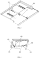
FIG. 1 is a structure diagram of a door gap compensator according to an embodiment of the present application, which shows an extended state of a floor body and a pedal body; -
FIG. 2 is a structure diagram of a door gap compensator according to an embodiment of the present application, which shows a retracted state of a floor body and a pedal body; -
FIG. 3 is a structure diagram of a door gap compensator according to an embodiment of the present application, which shows an extended state of a driving mechanism (air cylinder); -
FIG. 4 is a structure diagram of a door gap compensator according to an embodiment of the present application, which shows a retracted state of a driving mechanism (air cylinder); -
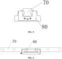
FIG. 5 is a front view of a sliding rail and sliding block cooperating in a door gap compensator according to an embodiment of the present application; -
FIG. 6 is a side view of a sliding rail and sliding block cooperating in a door gap compensator according to an embodiment of the present application; -
FIG. 7 is a front view of a door gap compensator according to an embodiment of the present application, which shows a floor body and a pedal body connected by a sliding rail and a sliding block; -
FIG. 8 is a front view of a door gap compensator according to an embodiment of the present application, which shows a sliding rail and a sliding block are not installed between a floor body and a pedal body; -
FIG. 9 is a section structure diagram of a rail vehicle according to an embodiment of the present application, which shows a door gap compensator in a retracted state; and -
FIG. 10 is a section structure diagram of a rail vehicle according to an embodiment of the present application, which shows a door gap compensator in an extended state. - 10: floor body; 11: straight guide groove; 20: pedal body; 30: air cylinder; 31: extension air inlet; 32: retraction air inlet; 33: locked air inlet; 40: first pin shaft; 50 second pin shaft; 60: magnetic control switch; 61: signal cable; 70: sliding rail; 80: sliding block; 90 adjustable gasket; 100: fastening bolt; 110: screw seat; 120: beam; 130: vehicle floor; 140: boundary beam.
- Detailed description of the implementation of the present application will be illustrated in combination with the accompanying drawings and embodiments. The following embodiments are used to illustrate the present application, but not to limit the scope of the present application.
- In the description of the present application, it is to be noted that, the orientation or positional relations specified by terms such as "central", "longitudinal", "transverse", "upper", "lower", "front", "back", "left", "right", "vertical", "horizontal", "top", "bottom", "inner", "outer" and the like, are based on the orientation or positional relations shown in the drawings, which is merely for convenience of description of the present application and to simplify description, but does not indicate or imply that the stated devices or components must have the particular orientation and be constructed and operated in a particular orientation, and thus it is not to be construed as limiting the present application. Furthermore, the terms "first", "second", "third" and the like are only used for descriptive purposes and should not be construed as indicating or implying a relative importance.
- In the description of the present application, it is to be noted that unless explicitly specified and defined otherwise, the terms "connected to" and "connected" shall be understood broadly, for example, it may be either fixedly connected or detachably connected, or can be integrated; it may be either mechanically connected, or electrically connected; it may be either directly connected, or indirectly connected through an intermediate medium; or it may be either a communication between two components. The specific meanings of the terms above in the present application can be understood by a person skilled in the art in accordance with specific conditions.
- In the embodiments of the present application, unless otherwise expressly specified and defined, a first feature is "on" or "under" a second feature can refer to that the first feature is directly contacted with the second feature, or the first feature is indirectly contacted with the second feature through an intermediate medium. And further, the first feature is "on", "above" and "over" the second feature can refer to that the first feature is directly above or obliquely above the second feature, or simply refer to that the level height of the first feature is higher than that of the second feature. The first feature is "under", "below" and "beneath" the second feature can refer to that the first feature is directly below or obliquely below the second feature, or simply refer to that the level height of the first feature is lower than that of the second feature.
- In the description of this specification, description with reference to the terms "one embodiment", "some embodiments", "an example", "specific example", "some examples" and the like, refers to that specific features, structures, materials or characteristics described in combination with an embodiment or an example are included in at least one embodiment or example according to the embodiments of the present application. In this specification, schematic representations of the above terms are not necessarily directed to a same embodiment or example. Furthermore, the particular features, structures, materials or characteristics described can be combined in any suitable manner in any one or more embodiments or examples. In addition, those skilled in the art may combine the different embodiments or examples described in this specification, as well as the features of the different embodiments or examples, without conflicting each other. In addition, the features involved in different embodiments described below can be combined as long as the features are not conflict to each other.
- As shown in
FIG. 1 to FIG. 10 , a system for controlling a door gap compensator provided by an embodiment of the present application includes anair cylinder 30, an inductive switch and a controller. - In an embodiment, the
air cylinder 30 is used to drive apedal body 20 to extend or retract horizontally along a bottom surface of afloor body 10. Theair cylinder 30 includes a cylinder body and a piston that extends or retracts along the cylinder body. The cylinder body is provided with anextension air inlet 31 and aretraction air inlet 32. Theextension air inlet 31 and theretraction air inlet 32 are respectively connected with an air pipeline connected to an air supply unit. When air is supplied to theextension air inlet 31 of theair cylinder 30, the piston of theair cylinder 30 is extended, and thepedal body 20 is pushed out in a direction of a platform. After thepedal body 20 is in place, a gap between the platform and a vehicle is reduced. When air is supplied to theretraction air inlet 32, the piston moves in a direction of the vehicle body, drives thepedal body 20 to retract the vehicle body without exceeding a vehicle limit. - The inductive switch is arranged on the
air cylinder 30 for sensing a position of the piston. For example, the piston is in a position not extended or not fully extended or in a fully extended position, the specific position of the piston is detected by the inductive switch, which is convenient to control the air supply time. - The controller is used to control the
extension air inlet 31 or theretraction air inlet 32 to intake air according to a position of the piston detected by the inductive switch, so as to control the piston to extend or retract to a specified position. The position specified here can be a preset position, so that a cylinder distance can be controlled to realize the control of a telescopic distance of thepedal body 20. This control method is simple and has high reliability. Once there is a failure that cannot be extended or retracted, it is easy to find the point of failure and solve it. - According to an embodiment of the present application, the extension air inlet and the retraction air inlet are respectively provided with a throttle valve to adjust the air intake volume, and the throttle valves are signally connected to the controller. By adjusting the opening degree of the throttle valve, the piston extension force or retraction force can be quickly adjusted. Similarly, by arranging the throttle valve, a telescope speed of the piston can also be adjusted.
- It should be noted that the "signally connected" can be either wired or wireless.
- According to an embodiment of the present application, the cylinder block is further provided with a locked
air inlet 33, which is connected with an air pipeline for connecting to the air supply unit. That is, the cylinder body is provided with anextension air inlet 31, aretraction air inlet 32 and a lockedair inlet 33. Theextension air inlet 31 is arranged at a back end of the cylinder body, that is, at a back end of the piston, and theretraction air inlet 32 is arranged at a front end of the cylinder body. The lockedair inlet 33 is arranged at a position of a front cylinder opening where a spring plug is arranged. Theextension air inlet 31, theretraction air inlet 32 and the lockedair inlet 33 are respectively used for connecting to the air supply unit of the vehicle body through an air pipeline, so as to facilitate the air supply unit of the vehicle body itself to supply air for theair cylinder 30, which is convenient to use. When air is supplied to theextension air inlet 31, the piston extends; and when air is supplied to theretraction air inlet 32, the piston retracts. By arranging the lockedair inlet 33, safety can be increased. For example, the premise of arranging theextended inlet 31 and the retractedinlet 32 to work normally is that the lockedair inlet 33 can supply air normally. When the lockedair inlet 33 is supplied with air, the spring plug can be lifted off, so that the air pipeline is communicated. The piston can extend or retract according to specific requirements. When the lockedair inlet 33 is out of air, the piston is locked and cannot extend or retract. In an event of an emergency or failure, theair inlet 33 can be directly cut off. The piston stopped in place, and there will not be situation where a passenger steps on thepedal body 20 and thepedal body 20 malfunctions and steps on empty, so as to improve safety. - According to an embodiment of the present application, the air pipeline of the
extension air inlet 31, the air pipeline of theretraction air inlet 32 and the air pipeline of the lockedair inlet 33 are respectively provided with a magnetic valve, and the magnetic valves are signally connected to the controller. On-off of the magnetic valve corresponds to an on-off of the air pipeline, so that the on-off of the air pipeline can be easily controlled by controlling the magnetic valve. For example, after the vehicle arrives at a station, a cab operates the door gap compensator to extend the button, and the magnetic valve on the air pipeline connecting theextension air inlet 31 is opened. The air pipeline receives a wind pressure signal, the air pipeline connected to theextension air inlet 31 of the air cylinder is open, and the piston extends to realize the extending of the pedal body of the door gap compensator. When the vehicle starts, the cab operates the door gap compensator retract button, and the corresponding magnetic valve opens. The air pipeline corresponding to the retraction air inlet receives the wind pressure signal, and the air pipeline connected to the retraction air inlet opens. The piston of the air cylinder retracts to realize the retraction of the pedal body of the door gap compensator. - According to an embodiment of the present application, the inductive switch is a
magnetic control switch 60. When the piston inside theair cylinder 30 passes through, themagnetic control switch 60 receives the corresponding signal and can provide the specific position of the piston of theair cylinder 30 to the vehicle. The vehicle can control air supply of the three air inlets of thecylinder 30 through the position of the piston to realize telescopic control of thepedal body 20. In an embodiment, themagnetic switch 60 includes a magnetic body (such as a magnet) and a moving contact that interacts with the magnetic body. The magnetic body of themagnetic switch 60 is arranged on the piston in the cylinder body, and a pair of moving contacts of themagnetic switch 60 is arranged by intervals outside the cylinder body. A spacing between two moving contacts is equal to a preset telescopic distance of theair cylinder 30. One of the moving contacts is arranged corresponding to a position where the piston does not extend and the magnetic body is provided. Another moving contact is arranged and spaced by a telescopic distance near a front end of the cylinder body.Signal cable 61 of the two moving contacts is signally connected to the controller. A position where the piston does not extend is triggered by the magnetic body to generate a signal and send it to a vehicle control system, that is, the controller. When the piston extends to a position where the magnetic body is opposite to another moving contact, this moving contact is triggered to generate a signal and send it to the vehicle control system, and the control system controls the piston to stop at position of the corresponding distance. For different vehicles, when the distance of the air cylinder needs to be adjusted, only the distance between the two moving contacts is needed to be adjusted. For example, an original distance of the air cylinder is 200 mm, now it needs to be adjusted to 250 mm, then the distance between the two moving contacts needs to be adjusted from 200 mm to 250 mm without change the air cylinder. Therefore, the control of a telescopic distance of the pedal body is conveniently realized, and the telescopic distance of the pedal body is adjustable. - In addition, when a vertical load above the
pedal body 20 exceeds a certain vertical load, the control system controls the piston to stop working, thereby ensuring the safety of personnel above thepedal body 20. - According to an embodiment of the present application, parallel pin holes are arranged at two ends of the
air cylinder 30, and the pin holes are arranged horizontally. Theair cylinder 30 includes a cylinder body and a piston that extends or retracts along the cylinder body. A fixed end of the cylinder body is rotatably connected to a back end bottom surface of afloor body 10 through afirst pin shaft 40. An extended end of the piston is rotatably connected to a front end bottom surface of thepedal body 20 through asecond pin shaft 50. The back end bottom surface of thefloor body 10 and the front end bottom surface of thepedal body 20 form a mounting base. Thefirst pin shaft 40 and thesecond pin shaft 50 respectively pass through a rotatable connecting hole of the mounting base and corresponding pin holes to install theair cylinder 30. After theair cylinder 30 is installed, an end of theair cylinder 30 is connected to thefloor body 10 and another end of theair cylinder 30 is connected to thepedal body 20. Thefirst pin shaft 40 and thesecond pin shaft 50 are parallel and horizontally arranged, and axial directions of thefirst pin shaft 40 and thesecond pin shaft 50 is perpendicular to a telescopic direction of the piston, so that thepedal body 20 has an ability to rotate along a vertical plane. When a vertical relative displacement is generated between thepedal body 20 and thefloor body 10, theair cylinder 30 can rotate along the pin shaft without generating internal stress. - In an embodiment, as shown in
FIG. 1 to FIG. 4 , the door gap compensator of an embodiment of the present application includes afloor body 10 and apedal body 20 and the system for controlling the door gap compensator mentioned above. In an embodiment, thefloor body 10 is configured to be fixedly embedded in an installation gap reserved on a floor in a door area of a vehicle body. The shape of thefloor body 10 can be square or rectangular, and an installation gap is square or rectangular adapted to the size and shape of thefloor body 10, so that thefloor body 10 can be better matched with the floor in the door area of the vehicle body after installation. - The
pedal body 20 is slidably connected to a bottom surface of thefloor body 10. n an embodiment, thepedal body 20 can slide in a straight line along thefloor body 10 in a direction pointing to the train platform. - This embodiment stipulates that a "a front end of the
floor body 10" and a "a front end of thepedal body 20" are ends near the platform, and a "a back end of thefloor body 10" and a "a back end of thepedal body 20" are ends away from the platform. - The
air cylinder 30 drives thepedal body 20 to extend or retract horizontally along thefloor body 10, and telescopic mode is highly reliable. Theair cylinder 30 provides power for a straight sliding of thepedal body 20, so that when thepedal body 20 needs to be extended, theair cylinder 30 provides the power to extend, and the drive thepedal body 20 to extend. When thepedal body 20 needs to be retracted, theair cylinder 30 provides the power to retract, and drive thepedal body 20 to retract. - The door gap compensator of the embodiment is embedded in the installation gap as an independent whole, which occupies small space, and is convenient to be installed, and has high reliability. An upper surface of the
floor body 10 after installation has the same height as the floor in a passenger room, and an overall matching degree with the vehicle body is high, which reduces steps at the door and improves passability of passengers or wheelchairs or other equipment, facilitates independent control of the door gap compensator. - As shown in
FIG. 5 to FIG. 8 , according to an embodiment of the present application, a slidingrail 70 and a slidingblock 80 are slidably connected between thepedal body 20 and thefloor body 10. When thepedal body 20 slides, the slidingblock 80 slides along the slidingrail 70. By arranging the slidingrail 70 to guide the slidingblock 80, stability and smoothness when thepedal body 20 slides can be ensured. In an embodiment, the slidingrail 70 is fixed at a bottom surface of thefloor body 10, and the specific fixation method can be fixed by fastener fixed connection or other fixed connection forms. A side of the slidingblock 80 facing the slidingrail 70 is provided with a sliding groove, and a side of the slidingblock 80 away from the sliding groove is fixedly connected to an upper surface of thepedal body 20. The specific fixation method can be fixed by fastener fixed connection or other fixed connection forms. The sliding groove of theslider 80 is clamped outside the slidingrail 70 and is slidably connected to theslide rail 70. The sliding groove can wrap the middle and lower parts of the slidingblock 80, so that after the slidingblock 80 is installed, there is a certain gap between the slidingblock 80 and the bottom surface of thefloor body 10, so as to avoid friction between the slidingblock 80 and thefloor body 10 during sliding. - According to an embodiment of the present application, a sliding joint of the sliding
rail 70 and the sliding groove is sealed with balls, and a lubricant is arranged in a sealed channel where the balls are arranged. The contact between the slidingrail 70 and the slidingblock 80 is carried out by the balls. When the slidingblock 80 moves on the slidingrail 70, it is rolling friction, and has small resistance. When thepedal body 20 extends and retracts, it does not have a large lateral displacement, which improves the stability of the door gap compensator. The balls in a sealed channel through the lubricant self-lubricating reduce maintenance cycles, and the lubricant can be lubricating oil or grease. In an embodiment, one row or two rows of balls can be arranged at the connection between the slidingrail 70 and the slidingblock 80. Firstly, grooves for installing the balls are arranged at relative positions of the slidingrail 70 and the slidingblock 80 respectively. The length direction of the grooves is along a sliding direction, and the two grooves form a sealed channel. Half of the balls are located in the grooves of the slidingrail 70, and another half of the balls is located in the grooves of the slidingblock 80. The slidingrail 70 and the slidingblock 80 are connected to each other. Through sealed treatment, the loss of lubricant can be avoided to reduce the frequency of increasing lubricant, and impurities such as dust can be prevented from entering the connection between slidingrail 70 and slidingblock 80. - In order to reduce or avoid sliding friction causing temperature rises during sliding due to the contact between the sliding grooves and the sliding
rail 70, two sides of the slidingrail 70 along its length direction are constructed as concave surfaces, and there is a gap between an inner wall of the sliding groove at the concave surface and the slidingrail 70. - According to an embodiment of the present application, the bottom surface of the
floor body 10 is constructed with a pair ofstraight guide grooves 11 for installing the slidingrail 70. The shape of a cross section of thestraight guide groove 11 is convex with a small upper part and a large lower part, that is, an opening of a lower opening groove of thestraight guide groove 11 is larger than that of an upper opening groove, and the lower opening groove is connected to the upper opening groove. An upper opening groove of thestraight guide groove 11 matches the slidingrail 70, and a lower opening groove of thestraight guide groove 11 has a gap outside the slidingblock 80. By formingstraight guide grooves 11 directly on thefloor body 10, the slidingblock 70 is directly clamped into the upper opening groove and the upper opening groove with interference fit during an installation of the slidingrail 70 without adjusting the orientation of the slidingblock rail 70. The installation is convenient and the positioning effect is good. The slidingrail 70 is stable and reliable after installation. A pair ofstraight guide grooves 11 are arranged in parallel, so that a pair of slidingrails 70 is also parallel to each other after installing. - A pair of the
straight guide grooves 11 are arranged on two sides of the air cylinder. The air cylinder can be in the middle of the door gap compensator. The pair of thestraight guide grooves 11 can be symmetrically arranged corresponding to the air cylinder, so that the sliding of thepedal body 20 is more stable. - According to an embodiment of the present application, an
adjustable gasket 90 is provided or not provided between the slidingblock 80 and thepedal body 20, that is, when the spacing between thepedal body 20 and thefloor body 10 does not need to be adjusted, anadjustable gasket 90 can be not installed; and when the spacing between thepedal body 20 and thefloor body 10 needs to be adjusted, the height difference between thepedal body 20 and thefloor body 10 can be adjusted by increasing or decreasing theadjustable gasket 90 between thepedal body 20 and the slidingblock 80 during the installation of the slidingblock 80. The height difference between thepedal body 20 and thefloor body 10 is a sum of a thickness of thefloor body 10 and a gap between thepedal body 20 and thefloor body 10. The thickness of thefloor body 10 itself is small, and the gap between thepedal body 20 and thefloor body 10 is adjustable, so that the height difference between thepedal body 20 and thefloor body 10 is small, which can meet the needs of getting on and off special equipment (such as wheelchairs). - In an embodiment, the sliding
rail 70 is fixedly connected to the bottom surface of thefloor body 10 by afastening bolt 100, and the slidingblock 80 is fixedly connected to an upper surface of thepedal body 20 by afastening bolt 100 to ensure connection strength and reliability. - According to an embodiment of the present application, the
floor body 10 and thepedal body 20 are formed by extrusion of an aluminum alloy hollow profile, which has high strength, light weight, good forming effect, and various required interfaces can be formed at one time. - In an embodiment, a hollow cavity is formed in the
floor body 10, and a row of parallelogram holes are spaced at a bottom of the cavity. The length direction of the parallelogram holes can be along a length direction of the hollow cavity. Ascrew base 110 is fixed at a connecting end (an end away from the head of the fastening bolt 100) of thefastening bolts 100. The shape of thescrew seat 110 is a parallelogram matched with the parallelogram hole, and the width of the hollow cavity is matched with the length of thescrew seat 110. Thescrew seat 110 extends into the hollow cavity along the length direction of the parallelogram hole, and rotates at a certain angle to make two sides of a length of thescrew seat 110 abut against two inner walls of a width of the cavity, thereby clamping thescrew seat 110 in the hollow cavity to ensure stability and firmness of thefastening bolts 100 after installing. In addition, the shape of thescrew seat 110 can also be elliptical, which can also achieve the same function. - When the
screw seat 110 is subjected to a large vertical impact, profile ribs can effectively play a supporting role, and stress concentration anomaly of a structure due to the hollow cavity will not occur. - The specific arrangement number of the
fastening bolts 100 can be selected according to actual needs. Thefastening bolts 100 adopting this connection form can realize rapid disassembly and convenient replacement. Correspondingly, a plurality of through holes for thefastening bolt 100 to pass through are arranged on the slidingrail 70 along its length direction. In order to avoid a head exposure of thefastening bolts 100, the through holes can be arranged as counterbores, and the heads of thefastening bolts 100 is located in the counterbores. - According to an embodiment of the present application, a part of the upper surface of the
pedal body 20 used to connect with the floor body is formed with a pair of installation interfaces symmetrical about a central axis of thepedal body 20. The slidingblock 80 is installed in the installation interface, and is fixedly connected to thepedal body 20 through thefastening bolt 100. The upper surface of thepedal body 20 is formed with anti-skid stripes avoiding the area where the pair of installation interfaces are located, which can increase anti-slip effect and avoid slipping. A front end of an upper surface of thefloor body 10 is formed with steps to fit a lower flange of the door body. Therefore, after the door is closed, the lower flange of the door body fits the steps. The sealed effect is increased, and installation space is reserved for the lower flange. After the lower flange fits the steps, an outer side of the lower flange is flush with a front end of thefloor body 10. - On the other hand, according to a method for controlling a door gap compensator of an embodiment of the present application,
when a signal that the door gap compensator extends or retracts is received, for example, after the vehicle arrives at a station, the cab operates the door gap compensator to extend the button, the system for controlling the door gap compensator receives the signal that the door gap compensator extends, the magnetic valve on the air pipeline connected to the extension air inlet is opened, the air pipeline receives a wind pressure signal, and the air pipeline connected to the extension air inlet of the air cylinder is opened, and the piston extending achieves the pedal body of the door gap compensator extending. When the vehicle starts, the driver's cab operates the door gap compensator to retract the bottom. The system for controlling the door gap compensate receives a retract signal of the door gap compensator, and the corresponding magnetic valve opens, and the air pipeline corresponding to the retraction air inlet receives the air pressure signal. The air pipeline connected to the retraction air inlet opens, and the piston of the pneumatic retracts to realize a retraction of the pedal body of the door gap compensator. According to a position of the piston of the cylinder, the controller controls the air pipeline of the extension air inlet or retraction air inlet to supply air to the extension air inlet or retraction air inlet, and controls the air cylinder to push the pedal body to extend horizontally along the bottom surface of the floor body to an opening position or to retract to a closing position. The opening position means that the pedal body extends to a maximum distance, and the closing position means that the pedal body retracts to a position in the vehicle body that does not occupy the space outside the vehicle. - On the other hand, the rail vehicle provided by embodiments of the present application includes a cab and the door gap compensator described above. The cab is provided with a button to control the system for controlling the door gap compensator. In an embodiment, it can be provided with an extension button to control an extension of the extension air inlet and a retraction button to control a retraction of the retraction air inlet. The extension air inlet and the retraction air inlet are respectively connected with an air supply unit of the rail vehicle through air pipelines. The air supply unit of the vehicle itself is used for air supply without providing with other air supply units, which is convenient to arrange and simple to operate.
- As shown in
FIG. 9 and FIG. 10 , a door area of this embodiment reserves an installation gap for installing the door gap compensator. A back end of thefloor body 10 is fixedly installed on abeam 120 of the vehicle body and is connected to a floor of the vehicle body. Thebeam 120 of the vehicle body bears the door gap compensator, which has strong bearing capacity and high reliability. The upper surface of thefloor body 10 being flush with the upper surface of the floor of the vehicle body makes the door gap compensator better matched with the vehicle after installation, reduces the steps at the door and improves the passability. The working principle of the door gap compensator is that when the piston of theair cylinder 30 extends, thepedal body 20 is pushed to extend to make up for a gap between the vehicle and the platform, and the piston is locked in an extending position after it is in place. When theair cylinder 30 piston retracts, thepedal body 20 is pulled back, hidden under thefloor body 10, consistent with the outer contour of the car body, and will not invade a limit. After thepedal body 20 is extended and retracted in place, the lockedair inlet 33 closes an air pressure, the piston of theair cylinder 30 is in a locked position, which cannot extend or retract to ensure safety. The door gap compensator of the embodiment is embedded in the installation gap as an independent whole, which has small space occupation, is convenient to install and has high reliability. The upper surface of thefloor body 10 after installation has the same as the height of the floor in a passenger room, and an overall matching degree with the vehicle body is high, which reduces the steps at the door and improves the passability of passengers or wheelchairs or other equipment. It is convenient for independent control of the system for controlling the door gap compensator. - According to an embodiment of the present application, the installation gap is opened from a door area floor to a
boundary beam 140 of the vehicle body, a front end of thefloor body 10 is flush with an outer side of theboundary beam 140, and does not occupy the space inside the vehicle after installation. The back end of thefloor body 10 is provided with a sealed gasket at a joint of the floor body and the floor of the vehicle body, which has good sealed performance. The upper surface of thefloor body 10 is provided with a floor cloth consistent with a floor cloth laid on the upper surface of the floor of the vehicle body, thus the door gap compensator is integrated with avehicle body floor 130, which has high matching degree. - Another embodiment of the present application provides a door gap compensator, including a
floor body 10, apedal body 20 and a driving mechanism. - In an embodiment, the
floor body 10 is configured to be fixedly embedded in an installation gap reserved on a floor in a door area of a vehicle body. The shape of thefloor body 10 can be square or rectangular, and the installation gap is square or rectangular matched the size and shape of thefloor body 10, so that thefloor body 10 can be better matched with the floor in the door area of the car body after installation. - The
pedal body 20 is slidably connected to the bottom surface of thefloor body 10. In an embodiment, thepedal body 20 can slide in a straight line along thefloor body 10 in the direction pointing to the train platform. - This embodiment stipulates that a "a front end of the
floor body 10" and a "a front end of thepedal body 20" are ends near the platform, and a "a back end of thefloor body 10" and a "a back end of thepedal body 20" are ends away from the platform. - The driving mechanism is configured to drive the
pedal body 20 to extend or retract horizontally along thefloor body 10, and telescopic mode is highly reliable. Theair cylinder 30 provides power for a straight sliding of thepedal body 20, so that when thepedal body 20 needs to be extended, theair cylinder 30 provides the power to extend, and the drive thepedal body 20 to extend. When thepedal body 20 needs to be retracted, theair cylinder 30 provides the power to retract, and drive thepedal body 20 to retract. - The door gap compensator of the embodiment is embedded in the installation gap as an independent whole, which occupies small space, and is convenient to be installed, and has high reliability. An upper surface of the
floor body 10 after installation has the same height as the floor in a passenger room, and an overall matching degree with the vehicle body is high, which reduces steps at the door and improves passability of passengers or wheelchairs or other equipment, facilitates independent control of the door gap compensator. - As shown in
FIG. 5 to FIG. 8 , according to an embodiment of the present application, a slidingrail 70 and a slidingblock 80 are slidably connected between thepedal body 20 and thefloor body 10. When thepedal body 20 slides, the slidingblock 80 slides along the slidingrail 70. By arranging the slidingrail 70 to guide the slidingblock 80, stability and smoothness when thepedal body 20 slides can be ensured. In an embodiment, the slidingrail 70 is fixed at a bottom surface of thefloor body 10, and the specific fixation method can be fixed by fastener fixed connection or other fixed connection forms. A side of the slidingblock 80 facing the slidingrail 70 is provided with a sliding groove, and a side of the slidingblock 80 away from the sliding groove is fixedly connected to an upper surface of thepedal body 20. The specific fixation method can be fixed by fastener fixed connection or other fixed connection forms. The sliding groove of theslider 80 is clamped outside the slidingrail 70 and is slidably connected to theslide rail 70. The sliding groove can wrap the middle and lower parts of the slidingblock 80, so that after the slidingblock 80 is installed, there is a certain gap between the slidingblock 80 and the bottom surface of thefloor body 10, so as to avoid friction between the slidingblock 80 and thefloor body 10 during sliding. - According to an embodiment of the present application, a sliding joint of the sliding
rail 70 and the sliding groove is sealed with balls, and a lubricant is arranged in a sealed channel where the balls are arranged. The contact between the slidingrail 70 and the slidingblock 80 is carried out by the balls. When the slidingblock 80 moves on the slidingrail 70, it is rolling friction, and has small resistance. When thepedal body 20 extends and retracts, it does not have a large lateral displacement, which improves the stability of the door gap compensator. The balls in a sealed channel through the lubricant self-lubricating reduce maintenance cycles, and the lubricant can be lubricating oil or grease. In an embodiment, one row or two rows of balls can be arranged at the connection between the slidingrail 70 and the slidingblock 80. Firstly, grooves for installing the balls are arranged at relative positions of the slidingrail 70 and the slidingblock 80 respectively. The length direction of the grooves is along a sliding direction, and the two grooves form a sealed channel. Half of the balls are located in the grooves of the slidingrail 70, and another half of the balls is located in the grooves of the slidingblock 80. The slidingrail 70 and the slidingblock 80 are connected to each other. Through sealed treatment, the loss of lubricant can be avoided to reduce the frequency of increasing lubricant, and impurities such as dust can be prevented from entering the connection between slidingrail 70 and slidingblock 80. - In order to reduce or avoid sliding friction causing temperature rises during sliding due to the contact between the sliding grooves and the sliding
rail 70, two sides of the slidingrail 70 along its length direction are constructed as concave surfaces, and there is a gap between an inner wall of the sliding groove at the concave surface and the slidingrail 70. - According to an embodiment of the present application, the bottom surface of the
floor body 10 is constructed with a pair ofstraight guide grooves 11 for installing the slidingrail 70. The shape of a cross section of thestraight guide groove 11 is convex with a small upper part and a large lower part, that is, an opening of a lower opening groove of thestraight guide groove 11 is larger than that of an upper opening groove, and the lower opening groove is connected to the upper opening groove. An upper opening groove of thestraight guide groove 11 matches the slidingrail 70, and a lower opening groove of thestraight guide groove 11 has a gap outside the slidingblock 80. By formingstraight guide grooves 11 directly on thefloor body 10, the slidingblock 70 is directly clamped into the upper opening groove and the upper opening groove with interference fit during an installation of the slidingrail 70 without adjusting the orientation of the slidingblock rail 70. The installation is convenient and the positioning effect is good. The slidingrail 70 is stable and reliable after installation. A pair ofstraight guide grooves 11 are arranged in parallel, so that a pair of slidingrails 70 is also parallel to each other after installing. - A pair of the
straight guide grooves 11 are arranged on two sides of the driving mechanism. The driving mechanism can be in the middle of the door gap compensator. The pair of thestraight guide grooves 11 can be symmetrically arranged corresponding to the driving mechanism, so that the sliding of thepedal body 20 is more stable. - According to an embodiment of the present application, an
adjustable gasket 90 is provided or not provided between the slidingblock 80 and thepedal body 20, that is, when the spacing between thepedal body 20 and thefloor body 10 does not need to be adjusted, anadjustable gasket 90 can be not installed; and when the spacing between thepedal body 20 and thefloor body 10 needs to be adjusted, the height difference between thepedal body 20 and thefloor body 10 can be adjusted by increasing or decreasing theadjustable gasket 90 between thepedal body 20 and the slidingblock 80 during the installation of the slidingblock 80. The height difference between thepedal body 20 and thefloor body 10 is a sum of a thickness of thefloor body 10 and a gap between thepedal body 20 and thefloor body 10. The thickness of thefloor body 10 itself is small, and the gap between thepedal body 20 and thefloor body 10 is adjustable, so that the height difference between thepedal body 20 and thefloor body 10 is small, which can meet the needs of getting on and off special equipment (such as wheelchairs). - In an embodiment, the sliding
rail 70 is fixedly connected to the bottom surface of thefloor body 10 by afastening bolt 100, and the slidingblock 80 is fixedly connected to an upper surface of thepedal body 20 by afastening bolt 100 to ensure connection strength and reliability. - According to an embodiment of the present application, the
floor body 10 and thepedal body 20 are formed by extrusion of an aluminum alloy hollow profile, which has high strength, light weight, good forming effect, and various required interfaces can be formed at one time. - In an embodiment, a hollow cavity is formed in the
floor body 10, and a row of parallelogram holes are spaced at a bottom of the cavity. The length direction of the parallelogram holes can be along a length direction of the hollow cavity. Ascrew base 110 is fixed at a connecting end (an end away from the head of the fastening bolts 100) of thefastening bolts 100. The shape of thescrew seat 110 is a parallelogram matched with the parallelogram hole, and the width of the hollow cavity is matched with the length of thescrew seat 110. Thescrew seat 110 extends into the hollow cavity along the length direction of the parallelogram hole, and rotates at a certain angle to make two sides of length of thescrew seat 110 abut against two inner walls of a width of the cavity, thereby clamping thescrew seat 110 in the hollow cavity to ensure stability and firmness of thefastening bolts 100 after installing. In addition, the shape of thescrew seat 110 can also be elliptical, which can also achieve the same function. - When the
screw seat 110 is subjected to a large vertical impact, profile ribs can effectively play a supporting role, and stress concentration anomaly of a structure due to the hollow cavity will not occur. - The specific arrangement number of the
fastening bolts 100 can be selected according to actual needs. Thefastening bolts 100 adopting this connection form can realize rapid disassembly and convenient replacement. Correspondingly, a plurality of through holes for thefastening bolt 100 to pass through are arranged on the slidingrail 70 along its length direction. In order to avoid a head exposure of thefastening bolts 100, the through holes can be arranged as counterbore, and the heads of thefastening bolts 100 is located in the counterbore. - According to an embodiment of the present application, a part of the upper surface of the
pedal body 20 used to connect with the floor body is formed with a pair of installation interfaces symmetrical about a central axis of thepedal body 20. The slidingblock 80 is installed in the installation interface, and is fixedly connected to thepedal body 20 through thefastening bolts 100. The upper surface of thepedal body 20 is formed with anti-skid stripes avoiding the area where the pair of installation interfaces are located, which can increase anti-slip effect and avoid slipping. A front end of an upper surface of thefloor body 10 is formed with steps to fit a lower flange of the door body. Therefore, after the door is closed, the lower flange of the door body fits the steps. The sealed effect is increased and installation space is reserved for the lower flange. After the lower flange fits the steps, an outer side of the lower flange is flush with a front end of thefloor body 10. - According to an embodiment of the present application, the driving mechanism is an
air cylinder 30. Parallel pin holes are arranged at two ends of theair cylinder 30, and the pin holes are arranged horizontally. Theair cylinder 30 includes a cylinder body and a piston that extends or retracts along the cylinder body. A fixed end of the cylinder body is rotatably connected to a back end bottom surface of afloor body 10 through afirst pin shaft 40. An extended end of the piston is rotatably connected to a front end bottom surface of thepedal body 20 through asecond pin shaft 50. The back end bottom surface of thefloor body 10 and the front end bottom surface of thepedal body 20 form a mounting base. Thefirst pin shaft 40 and thesecond pin shaft 50 respectively pass through a rotatable connecting hole of the mounting base and corresponding pin holes to install theair cylinder 30. After theair cylinder 30 is installed, an end of theair cylinder 30 is connected to thefloor body 10 and another end of theair cylinder 30 is connected to thepedal body 20. Thefirst pin shaft 40 and thesecond pin shaft 50 are parallel and horizontally arranged, and axial directions of thefirst pin shaft 40 and thesecond pin shaft 50 is perpendicular to a telescopic direction of the piston, so that thepedal body 20 has an ability to rotate along a vertical plane. When a vertical relative displacement is generated between thepedal body 20 and thefloor body 10, theair cylinder 30 can rotate along the pin shaft without generating internal stress. - According to an embodiment of the present application, the cylinder body is provided with an
extension air inlet 31, aretraction air inlet 32 and a lockedair inlet 33. Theextension air inlet 31 is arranged at a back end of the cylinder body, that is at a back end of the piston, and theretraction air inlet 32 is arranged at a front end of the cylinder body. The lockedair inlet 33 is arranged at a position of a front cylinder opening where a spring plug is arranged. Theextension air inlet 31, theretraction air inlet 32 and the lockedair inlet 33 are respectively used for connecting to the air supply unit of the vehicle body through an air channel, so as to facilitate the air supply unit of the vehicle body itself to supply air for theair cylinder 30, which is convenient to use. When air is supplied to theextension air inlet 31, the piston extends; and when air is supplied to theretraction air inlet 32, the piston retracts. The premise of arranging theextended inlet 31 and the retractedinlet 32 to work normally is that the lockedair inlet 33 can supply air normally. When the lockedair inlet 33 is supplied with air, the spring plug can be lifted off, so that the air channel is communicated. And the piston can extend or retract according to specific requirements. When the lockedair inlet 33 is out of air, the piston is locked and cannot extend or retract. In an event of an emergency or failure, theair inlet 33 can be directly cut off. The piston stopped in place, and there will not be situation where a passenger steps on empty because of stepping on thepedal body 20, so as to improve safety. - According to an embodiment of the present application, a throttle valve is arranged on at least one of the inlets of the
extension air inlet 31, theretraction air inlet 32 and the lockedair inlet 33. For example, a throttle valve can be arranged in theextension air inlet 31, theretraction air inlet 32 and the locked air inlet, or a throttle valve can be arranged at one or two of the inlets. The specific arrangement can be selected as needed. By arranging the throttle valve, the telescopic speed of the piston can be adjusted. - According to an embodiment of the present application, the
cylinder 30 is provided with amagnetic control switch 60. When the piston inside thecylinder 30 passes, themagnetic control switch 60 receives the corresponding signal, and can provide the specific position of thecylinder 30 piston to the vehicle. The vehicle controls the air supply volume of the three air inlets of thecylinder 30 through the position of the piston, and realizes telescopic control of thepedal body 20 of the door gap compensator. In an embodiment, themagnetic switch 60 includes a magnetic body (such as a magnet) and a moving contact that interacts with the magnetic body. The magnetic body of themagnetic switch 60 is arranged on the piston in the cylinder body, and a pair of moving contacts of themagnetic switch 60 is arranged by intervals outside the cylinder body. A spacing between two moving contacts is equal to a preset telescopic distance of theair cylinder 30. One of the moving contacts is arranged corresponding to a position where the piston does not extend and the magnetic body is provided. Another moving contact is arranged and spaced by a telescopic distance near a front end of the cylinder body. A position where the piston does not extend is triggered by the magnetic body to generate a signal and send it to a vehicle control system. When the piston extends to a position where the magnetic body is opposite to another moving contact, this moving contact is triggered to generate a signal and send it to the vehicle control system, and the control system controls the piston to stop at position of the corresponding distance. - In addition, when a certain vertical load is exceeded above the
pedal body 20, the control system controls the piston to stop working thereby ensuring the safety of the personnel above thepedal body 20. - As shown in
FIG. 9 and FIG. 10 , a rail vehicle according to the embodiment of the present application includes a vehicle body and the door gap compensator mentioned above. A door area floor of the vehicle body reserves an installation gap for installing the door gap compensator. A back end of thefloor body 10 is fixedly installed on abeam 120 of the vehicle body and is connected to a floor of the vehicle body. Thebeam 120 of the vehicle body bears the door gap compensator, which has strong bearing capacity and high reliability. The upper surface of thefloor body 10 being flush with an upper surface of the floor of the vehicle body makes the door gap compensator better matched with the vehicle after installation, reduces the steps at the door and improves the passability. The working principle of the door gap compensator is that when the piston of theair cylinder 30 extends, thepedal body 20 is pushed to extend to make up for a gap between the vehicle and the platform, and the piston is locked in an extending position after it is in place. When theair cylinder 30 piston retracts, thepedal body 20 is pulled back, hidden under thefloor body 10, consistent with the outer contour of the car body, and will not invade a limit. After thepedal body 20 is extended and retracted in place, the lockedair inlet 33 closes an air pressure, the piston of theair cylinder 30 is in a locked position, which cannot extend or retract to ensure safety. The door gap compensator of the embodiment is embedded in the installation gap as an independent whole, which has small occupation, is convenient to install and has high reliability. The upper surface of thefloor body 10 after installation has the same as the height of the floor in a passenger room, and an overall matching degree with the vehicle body is high, which reduces the steps at the door and improves the passability of passengers or wheelchairs or other equipment. It is convenient for independent control of the system for controlling door gap compensators. - According to an embodiment of the present application, the installation gap is opened from a door area floor to a
boundary beam 140 of the vehicle body, a front end of thefloor body 10 is flush with an outer side of theboundary beam 140, and does not occupy the space inside the vehicle after installation. The back end of thefloor body 10 is provided with a sealed gasket at a joint of the floor body and the floor of the vehicle body, which has good sealed performance. The upper surface of thefloor body 10 is provided with a floor cloth consistent with a floor cloth laid on the upper surface of the floor of the vehicle body, thus the door gap compensator is integrated with avehicle body floor 130, which has high matching degree. - It should be noted that the above embodiments are only examples for clear description, and are not limitations of the embodiments. For those skilled in the art, other different forms of modifications or replacements may be made on the basis of the above description. It is not necessary and cannot be exhaustive to show all embodiments. These modifications or replacements do not make the essence of the corresponding solutions depart from the scope of the solutions of various embodiments of the present application.
Claims (26)
- A system for controlling a door gap compensator, comprising:an air cylinder configured to drive a pedal body to extend or retract horizontally along a bottom surface of a floor body, wherein the air cylinder comprises a cylinder body and a piston extending or retracting along the cylinder body, the cylinder body is provided with an extension air inlet and a retraction air inlet, and the extension air inlet and the retraction air inlet are respectively connected with an air pipeline connected to an air supply unit;an inductive switch arranged on the air cylinder for sensing a position of the piston; anda controller configured to control the extension air inlet or the retraction air inlet to intake air according to a position of the piston detected by the inductive switch, so as to control the piston to extend or retract to a specified position.
- The door gap compensator control system according to claim 1, wherein the extension air inlet and the retraction air inlet are respectively provided with a throttle valve, and the throttle valves are signally connected to the controller.
- The door gap compensator control system according to claim 1, wherein the cylinder body is further provided with a locked air inlet, the locked air inlet is connected with an air pipeline for connecting to the air supply unit, and the air supply unit is an air supply system of a vehicle itself.
- The door gap compensator control system according to claim 3, wherein the air pipeline of the extension air inlet, the air pipeline of the retraction air inlet and the air pipeline of the locked air inlet are respectively provided with a magnetic valve, and the magnetic valves are signally connected to the controller.
- The door gap compensator control system according to any one of claims 1-4, wherein the inductive switch is a magnetic control switch, a magnetic body of the magnetic control switch is arranged on the piston in the cylinder body, a pair of moving contacts of the magnetic control switch is arranged by intervals outside the cylinder body, and a spacing between two moving contacts is equal to a preset telescopic distance of the air cylinder, wherein one of the moving contacts is arranged corresponding to a position where the piston does not extend and the magnetic body is provided.
- A door gap compensator, comprising a floor body, a pedal body, and a door gap compensator control system of any one of claims 1-5, wherein the floor body is configured to be fixedly embedded in an installation gap reserved on a floor in a door area of a vehicle body, the pedal body is slidably connected to a bottom surface of the floor body, and the air cylinder is configured to drive the pedal body to extend or retract horizontally along the floor body.
- The door gap compensator according to claim 6, wherein a fixed end of the cylinder body is rotatably connected to a back end bottom surface of the floor body through a first pin shaft, an extended end of the piston is rotatably connected to a front end bottom surface of the pedal body through a second pin shaft, the first pin shaft is arranged in parallel with the second pin shaft, and axial directions of the first pin shaft and the second pin shaft is perpendicular to a telescopic direction of the piston.
- The door gap compensator according to claim 7, wherein a sliding rail and a sliding block are slidably connected between the pedal body and the floor body, the sliding rail is fixed at a bottom surface of the floor body, a side of the sliding block facing the slide rail is provided with a sliding groove, a side of the sliding block away from the sliding groove is fixedly connected to an upper surface of the pedal body, and the sliding groove of the sliding block is clamped outside the sliding rail and is slidably connected to the sliding rail.
- The door gap compensator according to claim 8, wherein the sliding rail is fixedly connected to the bottom surface of the floor body by a fastening bolt, and the sliding block is fixedly connected to an upper surface of the pedal body by a fastening bolt.
- A method for controlling a door gap compensator, comprising:receiving an extending or retracting signal of the door gap compensator;controlling, by a controller, an air pipeline of an extension air inlet or a retraction air inlet of an air cylinder to supply air for the extension air inlet or the retraction air inlet according to a position of a piston of the air cylinder; andcontrolling the air cylinder to push a pedal body to extend horizontally along a bottom of a floor body to an open position or retract to a closed position.
- A rail vehicle, comprising cab, wherein further comprising the door gap compensator of any one of claims 6-8, wherein the cab is provided with a button to control the system for controlling the door gap compensator, and an extension air inlet and a retraction air inlet are respectively connected with an air supply unit of the rail vehicle through an air pipeline.
- A door gap compensator, comprising:a floor body configured to be fixedly embedded in an installation gap reserved on a floor in a door area of a vehicle body;a pedal body slidably connected to a bottom surface of the floor body; anda driving mechanism configured to drive the pedal body to extend or retract horizontally along the floor body.
- The door gap compensator according to claim 12, wherein a sliding rail and a sliding block are slidably connected between the pedal body and the floor body.
- The door gap compensator according to claim 13, wherein the sliding rail is fixed at a bottom surface of the floor body;a side of the sliding block facing the slide rail is provided with a sliding groove,a side of the sliding block away from the sliding groove is fixedly connected to an upper surface of the pedal body, andthe sliding groove of the sliding block is clamped outside the sliding rail and is slidably connected to the sliding rail.
- The door gap compensator according to claim 14, wherein a sliding joint of the sliding rail and the sliding groove is sealed with balls;a lubricant is arranged in a sealed channel where the balls are arranged; andtwo sides of the sliding rail along its length direction are constructed as concave surfaces.
- The door gap compensator according to claim 13, whereinthe bottom surface of the floor body is constructed with a pair of straight guide grooves for installing the sliding rail;the shape of a cross section of the straight guide groove is convex with a small upper part and a large lower part;an upper opening groove of the straight guide groove matches the sliding rail;a lower opening groove of the straight guide groove has a gap with an outside of the sliding block; andthe pair of the straight guide grooves are arranged on two sides of the driving mechanism.
- The door gap compensator according to claim 14, wherein an adjustable gasket is provided or not provided between the sliding block and the pedal body.
- The door gap compensator according to claim 13, wherein the sliding rail is fixedly connected to the bottom surface of the floor body by fastening bolts, and the sliding block is fixedly connected to an upper surface of the pedal body by a fastening bolt.
- The door gap compensator according to claim 18, wherein the floor body and the pedal body are formed by extrusion of an aluminum alloy hollow profile, a hollow cavity is formed in the floor body, and a row of parallelogram holes are spaced at a bottom of the cavity; a screw seat is fixed at a connecting end of the fastening bolts; a shape of the screw seat is a parallelogram matched with the parallelogram hole, and a width of the hollow cavity is matched with a length of the screw seat; and the screw seat extends into the hollow cavity along a length direction of the parallelogram hole, and rotates to make two sides of a length of the screw seat abut against two inner walls of a width of the cavity.
- The door gap compensator according to claim 19, wherein a pair of installation interfaces symmetrical about a central axis of the pedal body is formed on a part of an upper surface of the pedal body used to connect with the floor body, the upper surface of the pedal body is formed with anti-skid stripes avoiding the area where the pair of installation interfaces are located, and a front end of an upper surface of the floor body is formed with steps to fit a lower flange of the door body.
- The door gap compensator according to any one of claims 11-20, wherein the driving mechanism is an air cylinder, and the air cylinder comprises a cylinder body and a piston extending or retracting along the cylinder body; wherein a fixed end of the cylinder body is rotated and connected to a back bottom surface of the floor body through a first pin shaft, and an extended end of the piston is rotated and connected to a front bottom surface of the pedal body through a second pin shaft; and the first pin shaft is arranged in parallel with the second pin shaft, and axial directions of the first pin shaft and the second pin shaft are perpendicular to a telescopic direction of the piston.
- The door gap compensator according to claim 21, wherein the cylinder body is provided with an extension air inlet, a retraction air inlet and a locked air inlet; and the extension air inlet, the retraction air inlet and the locked air inlet are respectively connected to the air supply unit of the vehicle body through an air channel.
- The door gap compensator according to claim 22, wherein at least one of air inlets of the extension air inlet, the retraction air inlet or the locked air inlet is provided with a throttle valve.
- The door gap compensator according to claim 21, wherein the air cylinder is provided with a magnetic control switch, a magnetic body of the magnetic control switch is arranged on the piston in the cylinder body, a pair of moving contacts of the magnetic control switch is arranged by intervals outside the cylinder body, and a spacing between the pair of moving contacts is equal to a preset telescopic distance of the air cylinder, wherein one of the moving contacts is arranged corresponding to a position where the piston does not extend and the magnetic body is provided.
- A rail vehicle, comprising a vehicle body, wherein further comprising the door gap compensator of any one of claims 12-24, wherein a door area floor of the vehicle body reserves an installation gap for installing the door gap compensator, a back end of the floor body is fixedly installed on a beam of the vehicle body and is connected to a floor of the vehicle body, and an upper surface of the floor body is flush with an upper surface of the floor of the vehicle body.
- The rail vehicle according to claim 25, wherein the installation gap is opened from a door area floor to a boundary beam of the vehicle body, a front end of the floor body is flush with an outer side of the boundary beam, the back end of the floor body is provided with a sealed gasket at a joint of the floor body and the floor of the vehicle body, and the upper surface of the floor body is provided with a floor cloth consistent with a floor cloth laid on the upper surface of the floor of the vehicle body.
Applications Claiming Priority (3)
| Application Number | Priority Date | Filing Date | Title |
|---|---|---|---|
| CN202010346449.9A CN111516717B (en) | 2020-04-27 | 2020-04-27 | Door clearance compensator, door clearance compensator control system, method and rail vehicle |
| CN202010345747.6A CN111376936B (en) | 2020-04-27 | 2020-04-27 | Door clearance compensator and rail vehicle |
| PCT/CN2021/076528 WO2021218294A1 (en) | 2020-04-27 | 2021-02-10 | Door gap compensator, door gap compensator control system and method, and rail vehicle |
Publications (2)
| Publication Number | Publication Date |
|---|---|
| EP4144610A1 true EP4144610A1 (en) | 2023-03-08 |
| EP4144610A4 EP4144610A4 (en) | 2023-10-11 |
Family
ID=78331739
Family Applications (1)
| Application Number | Title | Priority Date | Filing Date |
|---|---|---|---|
| EP21797914.5A Pending EP4144610A4 (en) | 2020-04-27 | 2021-02-10 | DOOR GAP COMPENSATOR, DOOR GAP COMPENSATOR CONTROL SYSTEM AND METHOD, AND RAIL VEHICLE |
Country Status (3)
| Country | Link |
|---|---|
| EP (1) | EP4144610A4 (en) |
| CL (1) | CL2022002930A1 (en) |
| WO (1) | WO2021218294A1 (en) |
Families Citing this family (3)
| Publication number | Priority date | Publication date | Assignee | Title |
|---|---|---|---|---|
| CN114475682B (en) * | 2022-03-07 | 2023-08-08 | 唐山林德轨道交通设备有限公司 | Adjustable train pedal assembly |
| CN114590204B (en) * | 2022-03-11 | 2025-01-17 | 江铃汽车股份有限公司 | Intelligent control system and method for telescopic automobile side pedal |
| CN119459785B (en) * | 2024-11-28 | 2025-07-08 | 北京城铁科技集团有限公司 | A pedal device for a subway door system for electromechanical engineering |
Family Cites Families (9)
| Publication number | Priority date | Publication date | Assignee | Title |
|---|---|---|---|---|
| FR2928893B1 (en) * | 2008-03-20 | 2010-10-08 | Alstom Transport Sa | RAILWAY VEHICLE WITH MOBILE PLATFORM AND FOOTBOARD |
| JP5401084B2 (en) * | 2008-11-28 | 2014-01-29 | ナブテスコ株式会社 | Platform step device |
| CN203358601U (en) * | 2013-07-23 | 2013-12-25 | 广州铁路职业技术学院 | Automatic pedal device of vehicle door |
| CN105799600B (en) * | 2016-03-11 | 2018-02-13 | 河南科技大学 | Guider and telescopic pedal component, vehicle for telescopic pedal component |
| CN206187023U (en) * | 2016-11-14 | 2017-05-24 | 南京康尼机电股份有限公司 | A slip footboard device for rail transit train |
| DE202018102317U1 (en) * | 2018-04-25 | 2018-05-14 | Edag Engineering Gmbh | Footboard device |
| CN208760617U (en) * | 2018-07-30 | 2019-04-19 | 中车长春轨道客车股份有限公司 | A rail vehicle embedded built-in door pedal installation structure |
| CN111376936B (en) * | 2020-04-27 | 2025-01-21 | 中车青岛四方机车车辆股份有限公司 | Door clearance compensator and rail vehicle |
| CN111516717B (en) * | 2020-04-27 | 2021-08-24 | 中车青岛四方机车车辆股份有限公司 | Door clearance compensator, door clearance compensator control system, method and rail vehicle |
-
2021
- 2021-02-10 WO PCT/CN2021/076528 patent/WO2021218294A1/en not_active Ceased
- 2021-02-10 EP EP21797914.5A patent/EP4144610A4/en active Pending
-
2022
- 2022-10-24 CL CL2022002930A patent/CL2022002930A1/en unknown
Also Published As
| Publication number | Publication date |
|---|---|
| WO2021218294A1 (en) | 2021-11-04 |
| CL2022002930A1 (en) | 2023-07-07 |
| EP4144610A4 (en) | 2023-10-11 |
Similar Documents
| Publication | Publication Date | Title |
|---|---|---|
| CN111497878B (en) | Door clearance compensator pedal profile structure, door clearance compensator and rail vehicle | |
| CN111516717B (en) | Door clearance compensator, door clearance compensator control system, method and rail vehicle | |
| WO2021218294A1 (en) | Door gap compensator, door gap compensator control system and method, and rail vehicle | |
| CN107738582B (en) | Current collector of magnetic levitation vehicle | |
| CN113602299B (en) | Telescopic wing device for regulating aerodynamic force of high-speed train, high-speed train and control method | |
| US11077870B2 (en) | Side sliding door of railway vehicle | |
| CN115217395B (en) | A platform door | |
| EP2604488A1 (en) | Built-in plug-pull door device for track vehicle | |
| WO2005068247A3 (en) | Fixture for mounting a seat on a car floor by means of retractable guiding blocks | |
| CN111660819B (en) | Pantograph for track traffic | |
| CN217632049U (en) | Platform door | |
| CN111376936B (en) | Door clearance compensator and rail vehicle | |
| CN108413885B (en) | Station platform limit measurement device and measurement method | |
| CN111762218A (en) | rail vehicle | |
| CN211995569U (en) | Door clearance compensator and rail vehicle | |
| CN113799802A (en) | A large-opening rail transit platform door | |
| CN109720549A (en) | For the flap actuation system used in aircraft | |
| CN220706885U (en) | Monitoring device for vaccination medical vehicle | |
| CN220504839U (en) | Triple moving mechanism and triple moving door | |
| CN116252958A (en) | Air inlet air door device of auxiliary power system of airplane | |
| CN216737228U (en) | Rail difference leveling device | |
| CN117104283A (en) | A rail vehicle and its front-end opening and closing mechanism | |
| CN212670402U (en) | Lifting type supporting device on top cover of electric control channel gate machine at pedestrian entrance | |
| CN114876605A (en) | Valve driving device of engine and driving method thereof | |
| CN108149600A (en) | A kind of multifunction electronic banister for having the function of to intercept |
Legal Events
| Date | Code | Title | Description |
|---|---|---|---|
| STAA | Information on the status of an ep patent application or granted ep patent |
Free format text: STATUS: THE INTERNATIONAL PUBLICATION HAS BEEN MADE |
|
| PUAI | Public reference made under article 153(3) epc to a published international application that has entered the european phase |
Free format text: ORIGINAL CODE: 0009012 |
|
| STAA | Information on the status of an ep patent application or granted ep patent |
Free format text: STATUS: REQUEST FOR EXAMINATION WAS MADE |
|
| 17P | Request for examination filed |
Effective date: 20221013 |
|
| AK | Designated contracting states |
Kind code of ref document: A1 Designated state(s): AL AT BE BG CH CY CZ DE DK EE ES FI FR GB GR HR HU IE IS IT LI LT LU LV MC MK MT NL NO PL PT RO RS SE SI SK SM TR |
|
| DAV | Request for validation of the european patent (deleted) | ||
| DAX | Request for extension of the european patent (deleted) | ||
| A4 | Supplementary search report drawn up and despatched |
Effective date: 20230912 |
|
| RIC1 | Information provided on ipc code assigned before grant |
Ipc: B61D 23/00 20060101ALI20230906BHEP Ipc: B61D 19/02 20060101ALI20230906BHEP Ipc: B61D 23/02 20060101AFI20230906BHEP |
|
| STAA | Information on the status of an ep patent application or granted ep patent |
Free format text: STATUS: EXAMINATION IS IN PROGRESS |
|
| 17Q | First examination report despatched |
Effective date: 20260320 |