EP4144553B1 - Verfahren zur öl-vorkonditionierung für einen elektrischen antriebsstrang für ein fahrzeug - Google Patents
Verfahren zur öl-vorkonditionierung für einen elektrischen antriebsstrang für ein fahrzeug Download PDFInfo
- Publication number
- EP4144553B1 EP4144553B1 EP21194580.3A EP21194580A EP4144553B1 EP 4144553 B1 EP4144553 B1 EP 4144553B1 EP 21194580 A EP21194580 A EP 21194580A EP 4144553 B1 EP4144553 B1 EP 4144553B1
- Authority
- EP
- European Patent Office
- Prior art keywords
- gear
- primary
- coupling member
- tertiary
- electric motor
- Prior art date
- Legal status (The legal status is an assumption and is not a legal conclusion. Google has not performed a legal analysis and makes no representation as to the accuracy of the status listed.)
- Active
Links
Images

Classifications
-
- B—PERFORMING OPERATIONS; TRANSPORTING
- B60—VEHICLES IN GENERAL
- B60W—CONJOINT CONTROL OF VEHICLE SUB-UNITS OF DIFFERENT TYPE OR DIFFERENT FUNCTION; CONTROL SYSTEMS SPECIALLY ADAPTED FOR HYBRID VEHICLES; ROAD VEHICLE DRIVE CONTROL SYSTEMS FOR PURPOSES NOT RELATED TO THE CONTROL OF A PARTICULAR SUB-UNIT
- B60W30/00—Purposes of road vehicle drive control systems not related to the control of a particular sub-unit, e.g. of systems using conjoint control of vehicle sub-units
- B60W30/18—Propelling the vehicle
- B60W30/192—Mitigating problems related to power-up or power-down of the driveline, e.g. start-up of a cold engine
-
- B—PERFORMING OPERATIONS; TRANSPORTING
- B60—VEHICLES IN GENERAL
- B60K—ARRANGEMENT OR MOUNTING OF PROPULSION UNITS OR OF TRANSMISSIONS IN VEHICLES; ARRANGEMENT OR MOUNTING OF PLURAL DIVERSE PRIME-MOVERS IN VEHICLES; AUXILIARY DRIVES FOR VEHICLES; INSTRUMENTATION OR DASHBOARDS FOR VEHICLES; ARRANGEMENTS IN CONNECTION WITH COOLING, AIR INTAKE, GAS EXHAUST OR FUEL SUPPLY OF PROPULSION UNITS IN VEHICLES
- B60K1/00—Arrangement or mounting of electrical propulsion units
- B60K1/02—Arrangement or mounting of electrical propulsion units comprising more than one electric motor
-
- B—PERFORMING OPERATIONS; TRANSPORTING
- B60—VEHICLES IN GENERAL
- B60W—CONJOINT CONTROL OF VEHICLE SUB-UNITS OF DIFFERENT TYPE OR DIFFERENT FUNCTION; CONTROL SYSTEMS SPECIALLY ADAPTED FOR HYBRID VEHICLES; ROAD VEHICLE DRIVE CONTROL SYSTEMS FOR PURPOSES NOT RELATED TO THE CONTROL OF A PARTICULAR SUB-UNIT
- B60W10/00—Conjoint control of vehicle sub-units of different type or different function
- B60W10/04—Conjoint control of vehicle sub-units of different type or different function including control of propulsion units
- B60W10/08—Conjoint control of vehicle sub-units of different type or different function including control of propulsion units including control of electric propulsion units, e.g. motors or generators
-
- B—PERFORMING OPERATIONS; TRANSPORTING
- B60—VEHICLES IN GENERAL
- B60W—CONJOINT CONTROL OF VEHICLE SUB-UNITS OF DIFFERENT TYPE OR DIFFERENT FUNCTION; CONTROL SYSTEMS SPECIALLY ADAPTED FOR HYBRID VEHICLES; ROAD VEHICLE DRIVE CONTROL SYSTEMS FOR PURPOSES NOT RELATED TO THE CONTROL OF A PARTICULAR SUB-UNIT
- B60W10/00—Conjoint control of vehicle sub-units of different type or different function
- B60W10/10—Conjoint control of vehicle sub-units of different type or different function including control of change-speed gearings
- B60W10/11—Stepped gearings
-
- F—MECHANICAL ENGINEERING; LIGHTING; HEATING; WEAPONS; BLASTING
- F16—ENGINEERING ELEMENTS AND UNITS; GENERAL MEASURES FOR PRODUCING AND MAINTAINING EFFECTIVE FUNCTIONING OF MACHINES OR INSTALLATIONS; THERMAL INSULATION IN GENERAL
- F16H—GEARING
- F16H3/00—Toothed gearings for conveying rotary motion with variable gear ratio or for reversing rotary motion
- F16H3/02—Toothed gearings for conveying rotary motion with variable gear ratio or for reversing rotary motion without gears having orbital motion
- F16H3/08—Toothed gearings for conveying rotary motion with variable gear ratio or for reversing rotary motion without gears having orbital motion exclusively or essentially with continuously meshing gears, that can be disengaged from their shafts
- F16H3/087—Toothed gearings for conveying rotary motion with variable gear ratio or for reversing rotary motion without gears having orbital motion exclusively or essentially with continuously meshing gears, that can be disengaged from their shafts characterised by the disposition of the gears
- F16H3/089—Toothed gearings for conveying rotary motion with variable gear ratio or for reversing rotary motion without gears having orbital motion exclusively or essentially with continuously meshing gears, that can be disengaged from their shafts characterised by the disposition of the gears all of the meshing gears being supported by a pair of parallel shafts, one being the input shaft and the other the output shaft, there being no countershaft involved
-
- F—MECHANICAL ENGINEERING; LIGHTING; HEATING; WEAPONS; BLASTING
- F16—ENGINEERING ELEMENTS AND UNITS; GENERAL MEASURES FOR PRODUCING AND MAINTAINING EFFECTIVE FUNCTIONING OF MACHINES OR INSTALLATIONS; THERMAL INSULATION IN GENERAL
- F16H—GEARING
- F16H57/00—General details of gearing
- F16H57/04—Features relating to lubrication or cooling or heating
- F16H57/0409—Features relating to lubrication or cooling or heating characterised by increasing efficiency, e.g. by reducing splash losses
-
- F—MECHANICAL ENGINEERING; LIGHTING; HEATING; WEAPONS; BLASTING
- F16—ENGINEERING ELEMENTS AND UNITS; GENERAL MEASURES FOR PRODUCING AND MAINTAINING EFFECTIVE FUNCTIONING OF MACHINES OR INSTALLATIONS; THERMAL INSULATION IN GENERAL
- F16H—GEARING
- F16H57/00—General details of gearing
- F16H57/04—Features relating to lubrication or cooling or heating
- F16H57/0412—Cooling or heating; Control of temperature
- F16H57/0413—Controlled cooling or heating of lubricant; Temperature control therefor
-
- B—PERFORMING OPERATIONS; TRANSPORTING
- B60—VEHICLES IN GENERAL
- B60K—ARRANGEMENT OR MOUNTING OF PROPULSION UNITS OR OF TRANSMISSIONS IN VEHICLES; ARRANGEMENT OR MOUNTING OF PLURAL DIVERSE PRIME-MOVERS IN VEHICLES; AUXILIARY DRIVES FOR VEHICLES; INSTRUMENTATION OR DASHBOARDS FOR VEHICLES; ARRANGEMENTS IN CONNECTION WITH COOLING, AIR INTAKE, GAS EXHAUST OR FUEL SUPPLY OF PROPULSION UNITS IN VEHICLES
- B60K17/00—Arrangement or mounting of transmissions in vehicles
- B60K17/02—Arrangement or mounting of transmissions in vehicles characterised by arrangement, location, or kind of clutch
-
- B—PERFORMING OPERATIONS; TRANSPORTING
- B60—VEHICLES IN GENERAL
- B60W—CONJOINT CONTROL OF VEHICLE SUB-UNITS OF DIFFERENT TYPE OR DIFFERENT FUNCTION; CONTROL SYSTEMS SPECIALLY ADAPTED FOR HYBRID VEHICLES; ROAD VEHICLE DRIVE CONTROL SYSTEMS FOR PURPOSES NOT RELATED TO THE CONTROL OF A PARTICULAR SUB-UNIT
- B60W2710/00—Output or target parameters relating to a particular sub-units
- B60W2710/08—Electric propulsion units
- B60W2710/088—Temperature
-
- B—PERFORMING OPERATIONS; TRANSPORTING
- B60—VEHICLES IN GENERAL
- B60W—CONJOINT CONTROL OF VEHICLE SUB-UNITS OF DIFFERENT TYPE OR DIFFERENT FUNCTION; CONTROL SYSTEMS SPECIALLY ADAPTED FOR HYBRID VEHICLES; ROAD VEHICLE DRIVE CONTROL SYSTEMS FOR PURPOSES NOT RELATED TO THE CONTROL OF A PARTICULAR SUB-UNIT
- B60W2710/00—Output or target parameters relating to a particular sub-units
- B60W2710/10—Change speed gearings
- B60W2710/1072—Temperature
-
- B—PERFORMING OPERATIONS; TRANSPORTING
- B60—VEHICLES IN GENERAL
- B60Y—INDEXING SCHEME RELATING TO ASPECTS CROSS-CUTTING VEHICLE TECHNOLOGY
- B60Y2200/00—Type of vehicle
- B60Y2200/10—Road Vehicles
- B60Y2200/14—Trucks; Load vehicles, Busses
-
- B—PERFORMING OPERATIONS; TRANSPORTING
- B60—VEHICLES IN GENERAL
- B60Y—INDEXING SCHEME RELATING TO ASPECTS CROSS-CUTTING VEHICLE TECHNOLOGY
- B60Y2300/00—Purposes or special features of road vehicle drive control systems
- B60Y2300/18—Propelling the vehicle
- B60Y2300/192—Power-up or power-down of the driveline, e.g. start up of a cold engine
- B60Y2300/194—Power-up or power-down of the driveline, e.g. start up of a cold engine related to low temperature conditions, e.g. high viscosity of hydraulic fluid
-
- B—PERFORMING OPERATIONS; TRANSPORTING
- B60—VEHICLES IN GENERAL
- B60Y—INDEXING SCHEME RELATING TO ASPECTS CROSS-CUTTING VEHICLE TECHNOLOGY
- B60Y2306/00—Other features of vehicle sub-units
- B60Y2306/03—Lubrication
-
- F—MECHANICAL ENGINEERING; LIGHTING; HEATING; WEAPONS; BLASTING
- F16—ENGINEERING ELEMENTS AND UNITS; GENERAL MEASURES FOR PRODUCING AND MAINTAINING EFFECTIVE FUNCTIONING OF MACHINES OR INSTALLATIONS; THERMAL INSULATION IN GENERAL
- F16H—GEARING
- F16H2200/00—Transmissions for multiple ratios
- F16H2200/0021—Transmissions for multiple ratios specially adapted for electric vehicles
-
- F—MECHANICAL ENGINEERING; LIGHTING; HEATING; WEAPONS; BLASTING
- F16—ENGINEERING ELEMENTS AND UNITS; GENERAL MEASURES FOR PRODUCING AND MAINTAINING EFFECTIVE FUNCTIONING OF MACHINES OR INSTALLATIONS; THERMAL INSULATION IN GENERAL
- F16H—GEARING
- F16H2200/00—Transmissions for multiple ratios
- F16H2200/003—Transmissions for multiple ratios characterised by the number of forward speeds
- F16H2200/0034—Transmissions for multiple ratios characterised by the number of forward speeds the gear ratios comprising two forward speeds
-
- F—MECHANICAL ENGINEERING; LIGHTING; HEATING; WEAPONS; BLASTING
- F16—ENGINEERING ELEMENTS AND UNITS; GENERAL MEASURES FOR PRODUCING AND MAINTAINING EFFECTIVE FUNCTIONING OF MACHINES OR INSTALLATIONS; THERMAL INSULATION IN GENERAL
- F16H—GEARING
- F16H2200/00—Transmissions for multiple ratios
- F16H2200/003—Transmissions for multiple ratios characterised by the number of forward speeds
- F16H2200/0039—Transmissions for multiple ratios characterised by the number of forward speeds the gear ratios comprising three forward speeds
Definitions
- the invention relates to a method of oil pre-conditioning for an electric powertrain for a vehicle configured to provide electric propulsion of the vehicle.
- the invention applies to an electric powertrain integrated into a vehicle axle.
- Such electric axle (or “E-axle”) is a front or rear axle that includes an axle body (or “housing”) adapted to receive a powertrain, which is arranged to provide torque to the wheels of the axle.
- the "E-Axle” is a compact and economical electric drive solution for battery electric vehicles, fuel cells and hybrid applications. The electric motor(s), electronics and transmission are combined in a compact unit that directly drives the wheels.
- the invention can be applied in low-duty, medium-duty and heavy-duty vehicles, such as trucks, buses and construction equipment, as well as in passenger cars.
- low-duty, medium-duty and heavy-duty vehicles such as trucks, buses and construction equipment, as well as in passenger cars.
- the invention will be described with respect to a truck, the invention is not restricted to this particular vehicle type. Indeed, the electric powertrain of the invention could also be used in watercrafts such as ships or boats.
- Electro-mobility is mainly developed to meet increasingly stringent emission regulation requirements and the banning of internal combustion engine vehicles by some cities.
- the powertrain In order to free as much space as possible for batteries, chassis and other large parts, such as aerodynamic profiles, the powertrain must be as compact as possible.
- a gearbox with gears rotating at high speed also creates lubrication problems. Indeed, a gear rotating too fast may not be lubricated properly since the oil between two successive teeth is ejected by centrifugal force and metal-to-metal contact may occur between the teeth of the two gears in mesh, which generates heat and, consequently, potentially irreversible mechanical damage.
- a solution consists in heating the oil to reach the minimum sucking oil temperature before the vehicle starts. Nevertheless, the solution requires the use of additional devices to heat the oil such as an oil electric heater. This solution is expensive and difficult to implement on a vehicle. Furthermore, this solution taking some times, the driver has to wait a long time before driving the vehicle.
- An electric powertrain is known from WO 2021/121604 A1 .
- the invention aims more particularly to remedy, by proposing a more compact and robust electric powertrain, and making it possible to ensure a better efficiency of the electric motor in many conditions by offering several gear ratios. Additionally, the invention aims to provide an electric powertrain that heat the oil until the desired temperature leading to a reduction of the gears splashing and the gears contact.
- the object is achieved by a method of oil pre-conditioning for an electric powertrain for a vehicle configured to provide electric propulsion of the vehicle, said electric powertrain comprising:
- Said electric powertrain being such that the first electric motor linked to the first gear module, the second gear module, and the second electric motor linked to the third gear module extend parallel to each other and said electric powertrain being surrounded by an oil, the method comprising the steps of:
- the advantage is to provide an efficient heating of the oil until the desired temperature before the starting of the vehicle using robust and compact electric powertrains. Indeed, one of the first electric motor or the second electric motor rotates while the secondary shaft and therefore the wheels do not rotate leading to a reduction of gears splashing and gears contact generating heat. Furthermore, this method is easy to apply and allows the heating of the oil without the presence of the driver. Consequently, the method of oil pre-conditioning according to the present invention allow for a faster method, a reduction of the oil pre-conditioning costs and an increase of efficiency.
- the braking mode means that a force is applied at the brake wheel to stop the motion of one electric motor.
- a first pre-conditioning configuration is such that the first secondary coupling member is in neutral position, the first primary coupling member is engaged in a first position in which it couples the second primary gear and the first tertiary coupling member is engaged in a first position in which it couples the second tertiary gear.
- the first secondary coupling member is bidirectional leading to a higher efficiency to quickly heat the oil.
- the gears are submitted to a much higher torque, for example until the max motor torque capacity. Consequently, the gear contacts heat generation might be higher and the oil heating time might be lower. Moreover, the gears are rotating which might increase the churning loses and consequently the oil heating time.
- a second pre-conditioning configuration is such that the first secondary coupling member is in neutral position, a second secondary coupling member is in neutral position, the first primary coupling member is engaged in a first position in which it couples the second primary gear and the first tertiary coupling member is engaged in a first position in which it couples the second tertiary gear.
- the presence of the first secondary coupling member and the second secondary coupling member leads to a higher efficiency to quickly heat the oil.
- the gears are submitted and the gears are rotating increasing the churning loses and consequently the oil heating time.
- a third pre-conditioning configuration is such that the first secondary coupling member is in neutral position, a second secondary coupling member is in neutral position, the first primary coupling member is engaged in a second position in which it couples the third primary gear and the first tertiary coupling member is engaged in a second position in which it couples the third tertiary gear.
- the presence of the first secondary coupling member and the second secondary coupling member leads to a higher efficiency to quickly heat the oil.
- the electric powertrain is even more efficient resulting in a faster heating of the oil.
- the gears are submitted and the gears are rotating, increasing heat rejection into oil due to churning & friction and consequently the oil heating time.
- the first electric motor is in driving mode while the second electric motor is in braking mode.
- the first electric motor is in braking mode while the second electric motor is in driving mode.
- a control device selects an oil pre-conditioning configuration.
- the control device is linked to the electronic control unit (ECU).
- the control is integrated into the ECU.
- the ECU may select and/or apply an oil pre-conditioning configuration before the starting of the vehicle.
- step A) the vehicle is manually or automatically turned on.
- the driver may schedule the oil pre-conditioning at the desired time for example every day.
- the control device automatically turner on the vehicle and the oil pre-conditioning method.
- the driver may manually turned on the vehicle using for example the key.
- the control device automatically starts the oil pre-conditioning method.
- the threshold temperature is equal to below -20°C.
- X is defined as the longitudinal direction of the vehicle 1
- Y is defined as the transversal direction
- Z is defined as the vertical direction of the vehicle 1.
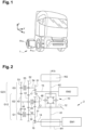
- Figure 1 shows a vehicle, which is an electric, fuel cell or hybrid vehicle, i.e. a vehicle using electric energy as a source of power.
- the vehicle is a truck 1, comprising two axles A 1a and A 1b , respectively a front axle A 1a and a rear axle A 1b .
- the vehicle may include one or more front and/or rear axle(s). Each axle can alternatively be none driven or driven axle(s).
- At least one of the two axles A 1a and A 1b is motorized, i.e. includes at least one electric motor.
- vehicle 1 is a propulsion vehicle (in which only the rear axle(s) is/are motorized).
- the invention obviously also applies to all-wheel drive vehicles and to traction vehicles (in which only the front axle(s) is/are motorized).
- Axle A1b includes a powertrain 2, comprising a first electric motor (or "E-motor") EM1, a first and a second electric motor EM1, EM2 or a second electric motor EM2.
- E-motor electric motor
- the two motors EM1 and EM2 are identical in that they have the same characteristics (supply voltage, operating current, torque-speed characteristic, mechanical power, etc.).
- the mechanical power of EM1 and EM2 are between 50kW to 500kw.
- the two motors EM1 and EM2 can be different.
- the electric motors EM1 and EM2 are AC type motors (synchronous or asynchronous).
- the electric motors EM1 and EM2 could be DC type motors as well (brushed). More generally, any electric motor is suitable.
- the electric powertrain 2 comprises a first primary gear 31, a second primary gear 32 and a third primary gear 33 arranged on a primary shaft 34 to obtain a first gear module G1 and a first electric motor EM1 linked to the first gear module G1.
- the first electric motor EM1 comprises a motor shaft (or “rotor shaft") 14 on which may be arranged a pinion 16 meshing with the first primary gear 31.
- the primary first primary gear 31 is fixed in rotation with respect to the primary shaft 34, the second primary gear 32 and a third primary gear 33.
- the primary first primary gear 31, the second primary gear 32 and a third primary gear 33 have each a different (outer diameter) and/or a different number of teeth.
- the primary first primary gear 31 has a diameter which is greater than that of the second primary gear 32 and the second primary gear 32 has a diameter that is greater than that of the third primary gear 33.
- the first primary gear 31 is integral with shaft 34 (i.e. made in one-piece).
- the first primary gear 31 could be fixedly attached to shaft 34 as well, using fasteners, welding, splines or press-fitting or any other means.
- the second primary gear 32 and the third primary gear 33 are, in this particular arrangement, by default each free to rotate around primary shaft 34.
- pinion 16 is fixed in rotation on motor shaft 14.
- pinion 16 can be integral with shaft 14, meaning that pinion 16 and shaft 14 form a unique part.
- a first primary coupling member 18 (also known as “gear shifting mechanism” or “dog clutch element”) is arranged along the primary shafts 34 and which is movable between a first position in which it couples the second primary gear 32 in rotation with primary shaft 34, a second position in which it couples the third primary gear 33 in rotation with primary shaft 34 and a neutral position in which it does not prevent the second and third primary gears 32, 33 from rotating around primary shaft 34.
- the electric powertrain 2 further comprises a first secondary gear 41 meshing with the first primary gear 31, a second secondary gear 42 meshing with the second primary gear 32, a third secondary gear 43 meshing with the third primary gear 33; said first secondary gear 41, second secondary gear 42 and third secondary gear 43 being arranged on a secondary shaft 44, also called “output shaft", to obtain a second gear module G2.
- a first secondary coupling member 40, 47 (also known as “gear shifting mechanism” or “dog clutch element”), which is arranged along the secondary shaft 44 and which can be moved between an engaged position, in which it couples the first secondary gear 41 in rotation with the secondary shaft 44 and a neutral position, in which it allows the first secondary gear 41 to rotate freely around the secondary shaft 44.
- the electric powertrain 2 comprises a first tertiary gear 51 configured to be fixed in rotation with respect to the tertiary shaft 54, a second tertiary gear 52 and a third tertiary gear 53 are arranged on the tertiary shaft 54.
- the first tertiary gear 51, the second tertiary gear 52 and the third tertiary gear 53 are arranged adjacent on the tertiary shaft 54 to obtain a third gear module G3.
- the second tertiary gear 52 and a third tertiary gear 53 are by default free to rotate around the tertiary shaft 54.
- the second tertiary gear 52 meshes with the second secondary gear 42 fitted on secondary shaft 44 and the third input gear 53 meshes with the third secondary gear 43.
- the first input gear 51 does not mesh with any secondary gear, in particular with the first secondary gear 41. Indeed, the first secondary gear 41 is not present on the secondary shaft 44.
- the second electric motor EM2 comprises a motor shaft 15.
- a pinion 17 is meshing with the first tertiary gear 51.
- the motor shaft 15 and the secondary shaft 44 extend parallel to each other.
- the two electric motors EM1 and EM2 are arranged transverse relative to the transversal direction of the vehicle, meaning that the axis of rotation of each motor EM1 and EM2 is perpendicular to the transversal direction of the vehicle. Accordingly, the powertrain 2 is said to be in a transverse configuration relative to the axle.
- the advantage of such transverse configuration is that it quite compact in the longitudinal side in comparison with a longitudinal configuration. To the contrary, a longitudinal arrangement requires less space in the transverse direction.
- EM1 linked to the first gear module G1, the second gear module G2 and EM2 linked to the third gear module G3 extend parallel to each other.
- the first gear module G1 is arranged in a first gear casing (not shown)
- the second gear module G2 is arranged in a second gear casing (not shown)
- the third gear module G3 is arranged in a third gear casing (not shown).
- the first gear casing, the second gear casing and the third gear casing are adjacent.
- the first gear module G1, the second gear module G2 and the third gear module G3 are arranged in a common gear casing (not shown).
- the electric motors EM1 and EM2 are encased inside the transmission housing. Alternatively, they could be outside of the transmission housing. In this case, the housing would include standard interfaces to assemble the electric motors EM1 and EM2.
- the electric motors EM1 and EM2 are powered by an electric power source, such as at least one battery or fuel cells, which are attached to another part of the vehicle, such as the chassis.
- an electric power source such as at least one battery or fuel cells
- the differential 10 is connected to both electric motors EM1 and EM2.
- the crown wheel 12 and the output gear 46 are conical gears (also called bevel gear).
- the first secondary gear 41 is arranged between the second secondary gear 42 and the output gear 46 and gear 42 is between gears 41 and 43, meaning that the output gear 46 is typically arranged at the end of shaft 44.
- the first gear module G1 is arranged in a first gear casing (not shown) and the second gear module G2 is arranged in a second gear casing (not shown), said first gear casing and the second gear casing being adjacent.
- the first gear module G1 and the second gear module G2 are arranged to obtain a gearbox G12.
- the first secondary gear 41 is by default free to rotate around the secondary shaft 44.
- the first gear module G1 and the second gear module G2 are arranged in a common gear casing (not shown).
- the second gear module G2 is arranged in a second gear casing (not shown) and the third gear module G3 is arranged in a third gear casing (not shown), the second and the third gear casings being adjacent.
- the second gear module G2 and the third gear module G3 are included in a gearbox G23.
- the first gear module G1 and the second gear module G2 are arranged in a common gear casing (not shown).
- a transmission unit includes a first electric motor EM1, a second electric motor EM2, a differential 10 and a gearbox G12, G23 comprising a first gear module G1, a second gear module G2 and a third gear module G3.
- the transmission ratios of gearbox G23 are different from that of gearbox G12.
- the first speed ratio of G12 (“EM1 gear 1") is lower than the first speed ratio of G23 ("EM2 gear 2")
- the first speed ratio of G23 (“EM2 gear 2")
- the second speed ratio of G12 (“EM1 gear 3")
- the second speed ratio of G12 (“EM1 gear 3") is lower than the second speed ratio of G23 ("EM2 gear 4").
- the third speed ratio of G12, or “gear cruising ratio” is higher than the second speed ratio of G23 ("EM2 gear 4").
- a first speed ratio (“EM1 gear 1") is obtained when the first coupling member 40, 47 is in neutral position and when the second coupling member 18 is in the second position.
- the torque is transmitted from the primary shaft 34 to the secondary shaft 44 through the pair of gears 33 and 43.
- the other gears, i.e. gears 32 and 41, are respectively unclutched from shafts 34 and 44.
- gears 32 and 41 are respectively unclutched from shafts 34 and 44.
- gears 32 and 41 are respectively unclutched from shafts 34 and 44.
- gears 32 and 41 are free to rotate around shaft 34 and 44, respectively.
- gears 32 and 41 remain immobile:
- Gears 32 and 42 are respectively rotationally driven by gears 43 and 31, which are each fixed in rotation with shaft 44 and 34, respectively.
- a second speed ratio (“EM1 gear 3"), different from the first speed ratio, is obtained when the first coupling member 40 is in neutral position and when the coupling member 18 is in first position.
- the torque is transmitted from the primary shaft 34 to the secondary shaft 44 through the pair of gears 32 and 42.
- the other gears i.e. gears 33 and 41, are respectively unclutched from shafts 34 and 44.
- gears 33 and 41 are free to rotate around shaft 34 and 44, respectively.
- gears 33 and 41 are respectively rotationally driven by gears 43 and 31, which are each fixed in rotation with shaft 34 and 44, respectively.
- a third speed ratio (“EM1 cruise gear”), different from the first two speed ratios, is obtained when the first coupling member 40 is in the engaged position and the second coupling member 18 is in the neutral position.
- the torque is transmitted from the primary shaft 34 to the secondary shaft 44 through the pair of gears 31 and 41.
- the other gears i.e. gears 32 and 33, are unclutched from shaft 34.
- gears 32 and 33 are independent from the rotation speed of the shaft 34.
- gears 32 and 33 are free to rotate around shaft 34. Nevertheless, it does not mean that gears 32 and 33 remain immobile: Gears 32 and 33 are respectively rotationally driven by gears 42 and 43, which are fixed in rotation with shaft 44.
- a first speed ratio (“EM2 gear 2”) is obtained when the coupling member 55 is in the second position.
- the torque is transmitted from the shaft 54 to the secondary shaft 44 through the pair of gears 53 and 43.
- gear 52 is independent from that of shaft 54.
- gear 52 is free to rotate around shaft 54. Nevertheless, it does not mean that gears 52 remains stationary.
- Gear 52 is rotationally driven by gear 42, which is fixed in rotation with shaft 44.
- a second speed ratio (“EM2 gear 4") is obtained when the coupling member 55 is in the first position.
- the torque is transmitted from the shaft 54 to the secondary shaft 44 through the pair of gears 52 and 42.
- gear 53 is independent from that of shaft 54.
- gear 53 is free to rotate around shaft 54. Nevertheless, it does not mean that gear 53 remains immobile.
- Gear 53 is rotationally driven by gear 43 which is fixed in rotation with shaft 44.
- the two gearboxes G12 and G23 form together a multi-input transmission, capable of selectively transmitting the torque of E-motor EM1 and the torque of E-motor EM2 (as inputs of the transmission) to the wheels, typically through the differential 10 (as output of the transmission).
- the electric powertrain 2 is surrounded by oil.
- the oil is sucked from an oil sump through an oil pump.
- the method of oil pre-conditioning comprises a step A) wherein an oil pre-conditioning configuration is selected.
- the secondary shaft 44 does not rotate and one of the first electric motor EM1 or the second electric motor EM2 is in braking mode while the other is in driving mode leading to the heating of the oil to reach a threshold temperature.
- step B the selected oil pre-conditioning configuration is then applied.
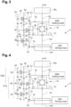
- Figures 2 and 3 illustrate an embodiment wherein in step A), a first pre-conditioning configuration is such that the first secondary coupling member 40 is in neutral position, the first primary coupling member 18 is engaged in a first position in which it couples the second primary gear 32 and the first tertiary coupling member 55 is engaged in a first position in which it couples the second tertiary gear 52.
- the first electric motor EM1 may be in driving mode while the second electric motor EM2 may be in braking mode.
- the first secondary coupling member 40 is bidirectional and the gears are submitted to a much higher torque leading to a higher generation of heat.
- Figures 4 and 5 illustrate an embodiment wherein in step A), a second pre-conditioning configuration is such that the first secondary coupling member 47 is in neutral position, a second secondary coupling member 48 is in neutral position, the first primary coupling member 18 is engaged in a first position in which it couples the second primary gear 32 and the first tertiary coupling member 55 is engaged in a first position in which it couples the second tertiary gear 52.
- the first electric motor EM1 may be in driving mode while the second electric motor EM2 may be in braking mode.
- the presence of the first secondary coupling member 47 and the second secondary coupling member 48 and the gears submitted to a much higher torque leading to an optimized oil heating.
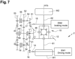
- Figures 6 and 7 illustrate an embodiment wherein in step A), a third pre-conditioning configuration is such that the first secondary coupling member 47 is in neutral position, a second secondary coupling member 48 is in neutral position, the first primary coupling member 18 is engaged in a second position in which it couples the third primary gear 33 and the first tertiary coupling member 55 is engaged in a second position in which it couples the third tertiary gear 53.
- the first electric motor EM1 may be in driving mode while the second electric motor EM2 may be in braking mode.
- the presence of the first secondary coupling member 47 and the second secondary coupling member 48 and the gears submitted to a much higher torque leading to an optimized oil heating.
- a control device selects an oil pre-conditioning configuration.
- the selection of the oil pre-conditioning configuration may be performed automatically or manually.
- the vehicle may be manually turned on by the driver or automatically turned on by the driver.
- the threshold temperature is equal to below -20°C.
- the method according to the present invention provides an efficient heating of the oil until the desired temperature before the starting of the vehicle. Furthermore, this method is cost saving and easily comprehensible.
Landscapes
- Engineering & Computer Science (AREA)
- Mechanical Engineering (AREA)
- General Engineering & Computer Science (AREA)
- Chemical & Material Sciences (AREA)
- Combustion & Propulsion (AREA)
- Transportation (AREA)
- Automation & Control Theory (AREA)
- Electric Propulsion And Braking For Vehicles (AREA)
Claims (9)
- Verfahren zur Vorkonditionierung des Öls für einen elektrischen Antriebsstrang (2) für ein Fahrzeug (1), der konfiguriert ist, um einen elektrischen Antrieb des Fahrzeugs (1) bereitzustellen, wobei der elektrische Antriebsstrang (2) umfasst:- eine Getriebeeinheit, die einen ersten Elektromotor (EM1), einen zweiten Elektromotor (EM2), ein Differential (10) und ein Getriebegehäuse (G12, G23) enthält, das ein erstes Getriebemodul (G1), ein zweites Getriebemodul (G2) und ein drittes Getriebemodul (G3) umfasst,- den ersten Elektromotor (EM1), der über eine Motorachse (14) mit dem ersten Getriebemodul (G1) verbunden ist, wobei das erste Getriebemodul (G1) eine Primärachse (34) enthält, auf der eine erste Primärwelle (31) angeordnet ist, die in Rotation in Bezug auf die Primärachse (34) montiert ist, eine zweite Primärwelle (32), eine dritte Primärwelle (33) und ein erstes Primärkupplungsglied (18),- eine Sekundärachse (44), die mit dem zweiten Getriebemodul (G2) verbunden ist, auf dem eine erste Sekundärwelle (41) angeordnet ist, die mit der ersten Primärwelle (31) eingreift, eine zweite Sekundärwelle (42), die mit der zweiten Primärwelle (32) eingreift, eine dritte Sekundärwelle (43), die mit der dritten Primärwelle (33) eingreift, und ein erstes Sekundärkupplungsglied (40, 47),- den zweiten Elektromotor (EM2), der über eine Motorachse (15) mit dem dritten Getriebemodul (G3) verbunden ist, wobei das dritte Getriebemodul (G3) eine Tertiärachse (54) enthält, auf der eine erste Tertiärwelle (51) angeordnet ist, die mit keiner Sekundärwelle eingreift, eine zweite Tertiärwelle (52), die mit der zweiten Sekundärwelle (42) eingreift, eine dritte Tertiärwelle (53), die mit der dritten Sekundärwelle (43) eingreift, und ein erstes Tertiärkupplungsglied (55), wobei die zweite Tertiärwelle (52) und die dritte Tertiärwelle (53) nebeneinander liegen,- das Differential (10), das von beiden Elektromotoren (EM1, EM2) verwendet wird,wobei der elektrische Antriebsstrang (2) derart ist, dass der erste Elektromotor (EM1), der mit dem ersten Getriebemodul (G1) verbunden ist, das zweite Getriebemodul (G2) und der zweite Elektromotor (EM2), der mit dem dritten Getriebemodul (G3) verbunden ist, parallel zueinander verlaufen, und der elektrische Antriebsstrang (2) von einem Öl umgeben ist, wobei das Verfahren dadurch gekennzeichnet ist, dass es die Schritte umfasst:A. Auswählen einer Konfiguration der Vorkonditionierung des Öls, wobei die Sekundärachse (44) nicht rotiert und mindestens einer von dem ersten Elektromotor (EM1) oder dem zweiten Elektromotor (EM2) in einem Bremsmodus rotiert, während sich der andere in einem Fahrmodus befindet, der zur Erwärmung des Öls führt, um eine Schwellentemperatur zu erreichen, undB. Anwenden der ausgewählten Konfiguration der Vorkonditionierung des Öls.
- Verfahren zur Vorkonditionierung des Öls nach Anspruch 1, wobei in Schritt A) eine erste Vorkonditionierungs-Konfiguration derart ist, dass sich das erste Sekundärkupplungsglied (40) in einer Neutralstellung befindet, das erste Primärkupplungsglied (18) in einer ersten Stellung eingerückt ist, in der es die zweite Primärwelle (32) koppelt, und das erste Tertiärkupplungsglied (55) in einer ersten Stellung eingerückt ist, in der es die zweite Tertiärwelle (52) koppelt.
- Verfahren zur Vorkonditionierung des Öls nach Anspruch 1 oder 2, wobei in Schritt A) eine zweite Vorkonditionierungs-Konfiguration derart ist, dass das erste Sekundärkupplungsglied (47) in Neutralstellung ist, ein zweites Sekundärkupplungsglied (48) in Neutralstellung ist, das erste Primärkupplungsglied (18) in einer ersten Stellung eingerückt ist, in der es die zweite Primärwelle (32) koppelt, und das erste Tertiärkupplungsglied (55) in einer ersten Stellung eingerückt ist, in der es die zweite Tertiärwelle (52) koppelt.
- Verfahren zur Vorkonditionierung des Öls nach einem der vorhergehenden Ansprüche, wobei in Schritt A) eine dritte Vorkonditionierungs-Konfiguration derart ist, dass das erste Sekundärkupplungsglied (47) in der Neutralstellung ist, ein zweites Sekundärkupplungsglied (48) in der Neutralstellung ist, das erste Primärkupplungsglied (18) in einer zweiten Stellung eingerückt ist, in der es die dritte Primärwelle (33) koppelt, und das erste Tertiärkupplungsglied (55) in einer zweiten Stellung eingerückt ist, in der es die dritte Tertiärwelle (53) koppelt.
- Verfahren zur Vorkonditionierung des Öls nach einem der vorhergehenden Ansprüche, wobei sich der erste Elektromotor (EM1) im Fahrmodus befindet, während sich der zweite Elektromotor (EM2) im Bremsmodus befindet.
- Verfahren zur Vorkonditionierung des Öls nach einem der Ansprüche 1 bis 4, wobei sich der erste Elektromotor (EM1) im Bremsmodus befindet, während sich der zweite Elektromotor (EM2) im Fahrmodus befindet.
- Verfahren zur Vorkonditionierung des Öls nach einem der vorhergehenden Ansprüche, wobei in Schritt A) eine Steuervorrichtung eine Konfiguration der Vorkonditionierung des Öls auswählt.
- Verfahren zur Vorkonditionierung des Öls nach einem der vorhergehenden Ansprüche, wobei vor dem Schritt A) das Fahrzeug manuell oder automatisch eingeschaltet wird.
- Verfahren zur Vorkonditionierung des Öls nach einem der vorhergehenden Ansprüche, wobei die Schwellentemperatur unter -20 °C liegt.
Priority Applications (3)
| Application Number | Priority Date | Filing Date | Title |
|---|---|---|---|
| EP21194580.3A EP4144553B1 (de) | 2021-09-02 | 2021-09-02 | Verfahren zur öl-vorkonditionierung für einen elektrischen antriebsstrang für ein fahrzeug |
| CN202211025059.7A CN115742739A (zh) | 2021-09-02 | 2022-08-25 | 用于车辆的电动动力系统的油预处理方法 |
| US17/929,069 US12337844B2 (en) | 2021-09-02 | 2022-09-01 | Method of oil pre-conditioning for an electric powertrain of a vehicle |
Applications Claiming Priority (1)
| Application Number | Priority Date | Filing Date | Title |
|---|---|---|---|
| EP21194580.3A EP4144553B1 (de) | 2021-09-02 | 2021-09-02 | Verfahren zur öl-vorkonditionierung für einen elektrischen antriebsstrang für ein fahrzeug |
Publications (3)
| Publication Number | Publication Date |
|---|---|
| EP4144553A1 EP4144553A1 (de) | 2023-03-08 |
| EP4144553C0 EP4144553C0 (de) | 2024-11-20 |
| EP4144553B1 true EP4144553B1 (de) | 2024-11-20 |
Family
ID=77989712
Family Applications (1)
| Application Number | Title | Priority Date | Filing Date |
|---|---|---|---|
| EP21194580.3A Active EP4144553B1 (de) | 2021-09-02 | 2021-09-02 | Verfahren zur öl-vorkonditionierung für einen elektrischen antriebsstrang für ein fahrzeug |
Country Status (3)
| Country | Link |
|---|---|
| US (1) | US12337844B2 (de) |
| EP (1) | EP4144553B1 (de) |
| CN (1) | CN115742739A (de) |
Families Citing this family (1)
| Publication number | Priority date | Publication date | Assignee | Title |
|---|---|---|---|---|
| DE102021211267A1 (de) * | 2021-10-06 | 2023-04-06 | Zf Friedrichshafen Ag | Elektrofahrzeuggetriebe |
Family Cites Families (12)
| Publication number | Priority date | Publication date | Assignee | Title |
|---|---|---|---|---|
| DE102005013598A1 (de) | 2005-03-24 | 2006-11-16 | Zf Friedrichshafen Ag | Verfahren zum Betreiben eines Antriebsstrangs eines Kraftfahrzeugs |
| WO2010131334A1 (ja) | 2009-05-12 | 2010-11-18 | トヨタ自動車株式会社 | ハイブリッド車両の制御装置 |
| DE102009026432A1 (de) | 2009-05-25 | 2010-12-09 | Zf Friedrichshafen Ag | Verfahren zum Betreiben eines Antriebsstrangs |
| JP4881991B2 (ja) | 2009-10-26 | 2012-02-22 | 本田技研工業株式会社 | 電気自動車の油温上昇制御方法及びその装置、並びに電気自動車 |
| JP5720664B2 (ja) * | 2012-12-06 | 2015-05-20 | トヨタ自動車株式会社 | 電動車両およびその制御方法 |
| CN104853970B (zh) | 2012-12-12 | 2017-07-28 | 丰田自动车株式会社 | 混合动力车辆的控制装置 |
| EP3184336B1 (de) * | 2015-12-21 | 2021-05-12 | Toyota Jidosha Kabushiki Kaisha | Fahrzeug mit einem fahrzeugkühlsystem |
| CN109177716B (zh) * | 2018-08-17 | 2019-11-26 | 宁波上中下自动变速器有限公司 | 用于混合动力车辆的动力系统 |
| EP4045820B1 (de) * | 2019-10-18 | 2023-11-22 | Volvo Truck Corporation | Antriebsstrang für ein fahrzeug |
| WO2021121604A1 (en) * | 2019-12-19 | 2021-06-24 | Volvo Truck Corporation | A gearbox for an electric powertrain |
| DE102020000449A1 (de) * | 2020-01-24 | 2021-07-29 | Man Truck & Bus Se | Getriebe mit Nebenabtrieb |
| US11407307B2 (en) * | 2020-03-23 | 2022-08-09 | Arvinmeritor Technology, Llc | Drive axle system having multiple electric motors |
-
2021
- 2021-09-02 EP EP21194580.3A patent/EP4144553B1/de active Active
-
2022
- 2022-08-25 CN CN202211025059.7A patent/CN115742739A/zh active Pending
- 2022-09-01 US US17/929,069 patent/US12337844B2/en active Active
Also Published As
| Publication number | Publication date |
|---|---|
| EP4144553A1 (de) | 2023-03-08 |
| US12337844B2 (en) | 2025-06-24 |
| US20230069392A1 (en) | 2023-03-02 |
| CN115742739A (zh) | 2023-03-07 |
| EP4144553C0 (de) | 2024-11-20 |
Similar Documents
| Publication | Publication Date | Title |
|---|---|---|
| JP7496875B2 (ja) | 電動パワートレイン用ギアボックス | |
| EP3750734B1 (de) | Hybridgetriebe und hybridelektrisches fahrzeug | |
| US12179571B2 (en) | Electric powertrain for a vehicle | |
| US11890928B2 (en) | Electric powertrain for a vehicle | |
| EP4048539B1 (de) | Fahrzeugachse, insbesondere motorisierte achse, auf der mehrere elektromotoren montiert sind | |
| EP3781427B1 (de) | Kettengetriebenes e-antriebs-getriebe | |
| EP3305616B1 (de) | Startsteuerungsvorrichtung für ein hybridfahrzeug | |
| US12337844B2 (en) | Method of oil pre-conditioning for an electric powertrain of a vehicle | |
| EP4055301B1 (de) | Getriebeanordnung für ein fahrzeug | |
| CN110758082B (zh) | 一种新能源车辆动力耦合装置及其控制方法 | |
| US12030377B2 (en) | Electric powertrain for a vehicle | |
| CN112477579A (zh) | 一种汽车驱动装置及汽车 | |
| CN112389186B (zh) | 混合动力总成及其控制方法 | |
| CN214138221U (zh) | 一种五轴混合动力变速机构 | |
| CN113232503B (zh) | 用于四轮驱动机动车的双电机行星混合动力传动装置 | |
| US20250340106A1 (en) | Hybrid electric variable transmission for all-wheel drive off-road capable vehicle | |
| CN117124834A (zh) | 一种纯电动行走举升二合一动力总成 | |
| CN119705049A (zh) | 一种二档带取力器商用车电驱桥 | |
| CN114953982A (zh) | 一种适用于纯电动汽车的双电机两挡电驱系统及其控制方法 |
Legal Events
| Date | Code | Title | Description |
|---|---|---|---|
| PUAI | Public reference made under article 153(3) epc to a published international application that has entered the european phase |
Free format text: ORIGINAL CODE: 0009012 |
|
| STAA | Information on the status of an ep patent application or granted ep patent |
Free format text: STATUS: THE APPLICATION HAS BEEN PUBLISHED |
|
| AK | Designated contracting states |
Kind code of ref document: A1 Designated state(s): AL AT BE BG CH CY CZ DE DK EE ES FI FR GB GR HR HU IE IS IT LI LT LU LV MC MK MT NL NO PL PT RO RS SE SI SK SM TR |
|
| STAA | Information on the status of an ep patent application or granted ep patent |
Free format text: STATUS: REQUEST FOR EXAMINATION WAS MADE |
|
| 17P | Request for examination filed |
Effective date: 20230906 |
|
| RBV | Designated contracting states (corrected) |
Designated state(s): AL AT BE BG CH CY CZ DE DK EE ES FI FR GB GR HR HU IE IS IT LI LT LU LV MC MK MT NL NO PL PT RO RS SE SI SK SM TR |
|
| GRAP | Despatch of communication of intention to grant a patent |
Free format text: ORIGINAL CODE: EPIDOSNIGR1 |
|
| STAA | Information on the status of an ep patent application or granted ep patent |
Free format text: STATUS: GRANT OF PATENT IS INTENDED |
|
| RIC1 | Information provided on ipc code assigned before grant |
Ipc: F16H 57/04 20100101ALI20240607BHEP Ipc: F16H 3/089 20060101ALI20240607BHEP Ipc: F16H 3/00 20060101ALI20240607BHEP Ipc: B60K 17/02 20060101ALI20240607BHEP Ipc: B60K 1/02 20060101AFI20240607BHEP |
|
| INTG | Intention to grant announced |
Effective date: 20240624 |
|
| RIN1 | Information on inventor provided before grant (corrected) |
Inventor name: GRANOTTIER, NICOLAS Inventor name: BARILLOT, THOMAS Inventor name: BROLLES, VINCENT |
|
| GRAS | Grant fee paid |
Free format text: ORIGINAL CODE: EPIDOSNIGR3 |
|
| GRAA | (expected) grant |
Free format text: ORIGINAL CODE: 0009210 |
|
| STAA | Information on the status of an ep patent application or granted ep patent |
Free format text: STATUS: THE PATENT HAS BEEN GRANTED |
|
| AK | Designated contracting states |
Kind code of ref document: B1 Designated state(s): AL AT BE BG CH CY CZ DE DK EE ES FI FR GB GR HR HU IE IS IT LI LT LU LV MC MK MT NL NO PL PT RO RS SE SI SK SM TR |
|
| REG | Reference to a national code |
Ref country code: GB Ref legal event code: FG4D |
|
| REG | Reference to a national code |
Ref country code: CH Ref legal event code: EP |
|
| REG | Reference to a national code |
Ref country code: DE Ref legal event code: R096 Ref document number: 602021022007 Country of ref document: DE |
|
| REG | Reference to a national code |
Ref country code: IE Ref legal event code: FG4D |
|
| U01 | Request for unitary effect filed |
Effective date: 20241122 |
|
| U07 | Unitary effect registered |
Designated state(s): AT BE BG DE DK EE FI FR IT LT LU LV MT NL PT RO SE SI Effective date: 20241129 |
|
| PG25 | Lapsed in a contracting state [announced via postgrant information from national office to epo] |
Ref country code: IS Free format text: LAPSE BECAUSE OF FAILURE TO SUBMIT A TRANSLATION OF THE DESCRIPTION OR TO PAY THE FEE WITHIN THE PRESCRIBED TIME-LIMIT Effective date: 20250320 Ref country code: HR Free format text: LAPSE BECAUSE OF FAILURE TO SUBMIT A TRANSLATION OF THE DESCRIPTION OR TO PAY THE FEE WITHIN THE PRESCRIBED TIME-LIMIT Effective date: 20241120 |
|
| PG25 | Lapsed in a contracting state [announced via postgrant information from national office to epo] |
Ref country code: ES Free format text: LAPSE BECAUSE OF FAILURE TO SUBMIT A TRANSLATION OF THE DESCRIPTION OR TO PAY THE FEE WITHIN THE PRESCRIBED TIME-LIMIT Effective date: 20241120 |
|
| PG25 | Lapsed in a contracting state [announced via postgrant information from national office to epo] |
Ref country code: NO Free format text: LAPSE BECAUSE OF FAILURE TO SUBMIT A TRANSLATION OF THE DESCRIPTION OR TO PAY THE FEE WITHIN THE PRESCRIBED TIME-LIMIT Effective date: 20250220 |
|
| PG25 | Lapsed in a contracting state [announced via postgrant information from national office to epo] |
Ref country code: GR Free format text: LAPSE BECAUSE OF FAILURE TO SUBMIT A TRANSLATION OF THE DESCRIPTION OR TO PAY THE FEE WITHIN THE PRESCRIBED TIME-LIMIT Effective date: 20250221 |
|
| PG25 | Lapsed in a contracting state [announced via postgrant information from national office to epo] |
Ref country code: PL Free format text: LAPSE BECAUSE OF FAILURE TO SUBMIT A TRANSLATION OF THE DESCRIPTION OR TO PAY THE FEE WITHIN THE PRESCRIBED TIME-LIMIT Effective date: 20241120 |
|
| PG25 | Lapsed in a contracting state [announced via postgrant information from national office to epo] |
Ref country code: RS Free format text: LAPSE BECAUSE OF FAILURE TO SUBMIT A TRANSLATION OF THE DESCRIPTION OR TO PAY THE FEE WITHIN THE PRESCRIBED TIME-LIMIT Effective date: 20250220 |
|
| PG25 | Lapsed in a contracting state [announced via postgrant information from national office to epo] |
Ref country code: SM Free format text: LAPSE BECAUSE OF FAILURE TO SUBMIT A TRANSLATION OF THE DESCRIPTION OR TO PAY THE FEE WITHIN THE PRESCRIBED TIME-LIMIT Effective date: 20241120 |
|
| PG25 | Lapsed in a contracting state [announced via postgrant information from national office to epo] |
Ref country code: SK Free format text: LAPSE BECAUSE OF FAILURE TO SUBMIT A TRANSLATION OF THE DESCRIPTION OR TO PAY THE FEE WITHIN THE PRESCRIBED TIME-LIMIT Effective date: 20241120 |
|
| PG25 | Lapsed in a contracting state [announced via postgrant information from national office to epo] |
Ref country code: CZ Free format text: LAPSE BECAUSE OF FAILURE TO SUBMIT A TRANSLATION OF THE DESCRIPTION OR TO PAY THE FEE WITHIN THE PRESCRIBED TIME-LIMIT Effective date: 20241120 |
|
| PLBE | No opposition filed within time limit |
Free format text: ORIGINAL CODE: 0009261 |
|
| STAA | Information on the status of an ep patent application or granted ep patent |
Free format text: STATUS: NO OPPOSITION FILED WITHIN TIME LIMIT |
|
| 26N | No opposition filed |
Effective date: 20250821 |
|
| U20 | Renewal fee for the european patent with unitary effect paid |
Year of fee payment: 5 Effective date: 20250925 |