EP4144482A1 - Torque application apparatus - Google Patents
Torque application apparatus Download PDFInfo
- Publication number
- EP4144482A1 EP4144482A1 EP22190579.7A EP22190579A EP4144482A1 EP 4144482 A1 EP4144482 A1 EP 4144482A1 EP 22190579 A EP22190579 A EP 22190579A EP 4144482 A1 EP4144482 A1 EP 4144482A1
- Authority
- EP
- European Patent Office
- Prior art keywords
- base
- pins
- cam
- set screw
- rotation
- Prior art date
- Legal status (The legal status is an assumption and is not a legal conclusion. Google has not performed a legal analysis and makes no representation as to the accuracy of the status listed.)
- Granted
Links
Images


Classifications
-
- B—PERFORMING OPERATIONS; TRANSPORTING
- B25—HAND TOOLS; PORTABLE POWER-DRIVEN TOOLS; MANIPULATORS
- B25B—TOOLS OR BENCH DEVICES NOT OTHERWISE PROVIDED FOR, FOR FASTENING, CONNECTING, DISENGAGING, OR HOLDING
- B25B13/00—Spanners; Wrenches
- B25B13/48—Spanners; Wrenches for special purposes
- B25B13/50—Spanners; Wrenches for special purposes for operating on work of special profile, e.g. pipes
- B25B13/5008—Spanners; Wrenches for special purposes for operating on work of special profile, e.g. pipes for operating on pipes or cylindrical objects
-
- B—PERFORMING OPERATIONS; TRANSPORTING
- B25—HAND TOOLS; PORTABLE POWER-DRIVEN TOOLS; MANIPULATORS
- B25B—TOOLS OR BENCH DEVICES NOT OTHERWISE PROVIDED FOR, FOR FASTENING, CONNECTING, DISENGAGING, OR HOLDING
- B25B23/00—Details of, or accessories for, spanners, wrenches, screwdrivers
- B25B23/14—Arrangement of torque limiters or torque indicators in wrenches or screwdrivers
- B25B23/142—Arrangement of torque limiters or torque indicators in wrenches or screwdrivers specially adapted for hand operated wrenches or screwdrivers
- B25B23/1422—Arrangement of torque limiters or torque indicators in wrenches or screwdrivers specially adapted for hand operated wrenches or screwdrivers torque indicators or adjustable torque limiters
- B25B23/1427—Arrangement of torque limiters or torque indicators in wrenches or screwdrivers specially adapted for hand operated wrenches or screwdrivers torque indicators or adjustable torque limiters by mechanical means
-
- B—PERFORMING OPERATIONS; TRANSPORTING
- B25—HAND TOOLS; PORTABLE POWER-DRIVEN TOOLS; MANIPULATORS
- B25B—TOOLS OR BENCH DEVICES NOT OTHERWISE PROVIDED FOR, FOR FASTENING, CONNECTING, DISENGAGING, OR HOLDING
- B25B13/00—Spanners; Wrenches
- B25B13/44—Spanners; Wrenches of the chuck type
-
- B—PERFORMING OPERATIONS; TRANSPORTING
- B25—HAND TOOLS; PORTABLE POWER-DRIVEN TOOLS; MANIPULATORS
- B25B—TOOLS OR BENCH DEVICES NOT OTHERWISE PROVIDED FOR, FOR FASTENING, CONNECTING, DISENGAGING, OR HOLDING
- B25B23/00—Details of, or accessories for, spanners, wrenches, screwdrivers
- B25B23/14—Arrangement of torque limiters or torque indicators in wrenches or screwdrivers
- B25B23/141—Mechanical overload release couplings
-
- B—PERFORMING OPERATIONS; TRANSPORTING
- B25—HAND TOOLS; PORTABLE POWER-DRIVEN TOOLS; MANIPULATORS
- B25B—TOOLS OR BENCH DEVICES NOT OTHERWISE PROVIDED FOR, FOR FASTENING, CONNECTING, DISENGAGING, OR HOLDING
- B25B27/00—Hand tools, specially adapted for fitting together or separating parts or objects whether or not involving some deformation, not otherwise provided for
- B25B27/0035—Hand tools, specially adapted for fitting together or separating parts or objects whether or not involving some deformation, not otherwise provided for for motor-vehicles
-
- B—PERFORMING OPERATIONS; TRANSPORTING
- B60—VEHICLES IN GENERAL
- B60G—VEHICLE SUSPENSION ARRANGEMENTS
- B60G13/00—Resilient suspensions characterised by arrangement, location or type of vibration dampers
- B60G13/001—Arrangements for attachment of dampers
Definitions
- Dampers are typically used in conjunction with automotive suspension systems or other suspension systems to control movement of wheels of a vehicle relative to a body of the vehicle.
- dampers are generally connected between the sprung (body) and the unsprung (suspension/drivetrain) masses of the vehicle. Components of the dampers may be engaged with each other via threads, e.g., the components may be screwed together.
- An apparatus for applying torque to a body of a damper assembly includes a base defining an inner chamber.
- the apparatus includes a plurality of pins supported by base and disposed in the inner chamber.
- the plurality of pins are moveable relative to the base between engaged positions and disengaged positions.
- the apparatus includes a trigger actuatable to move at least one of the plurality of pins to the disengaged position.
- an assembly is formed with the body disposed in the inner chamber of the base.
- the pins, in the engaged positions, are disposed in the plurality of openings.
- the pins, in the disengaged positions, are out of the openings. Movement of the pins between the engaged position and the disengaged position enables the apparatus to be easily engaged with the body to apply torque thereto to be easily disengaged from the body to separate the apparatus from the body, e.g., after application of torque.
- a vehicle 20 having a plurality of damper assemblies 22 is shown.
- the vehicle 20 may be any suitable type of ground vehicle, e.g., a passenger or commercial automobile such as a sedan, a coupe, a truck, a sport utility, a crossover, a van, a minivan, a taxi, a bus, etc.
- damper assemblies 22 are typically used in conjunction with automotive suspension systems or other suspension systems to control movement of wheels of the vehicle 20 relative to a body of the vehicle 20.
- damper assemblies 22 are generally connected between the sprung (body) and the unsprung (suspension/drivetrain) masses of the vehicle 20.
- Each damper assembly 22 may be coupled with a coil spring.
- Each damper assembly 22 is movable from a compressed position to an extended position, and vice versa.
- a distance between ends of the damper assembly 22, i.e., the distance from one end to the other end, is less in the compressed position than in the extended position.
- the coil springs, or the like may urge the damper assemblies 22 toward the extended positions.
- Force applied to wheels of the vehicle 20, e.g., from bumps, potholes, etc. may urge to damper assemblies 22 toward the compressed position.
- Each damper assembly 22 controls movement of respective wheels by limiting fluid flow into, out of, and/or between various chambers of the damper assembly 22, e.g., into, out of, and/or between a compression chamber and a rebound chamber, between a reserve chamber and the compression chamber and/or the rebound chamber, etc. Fluid movement is caused by movement of a piston within a pressure tube of the damper assembly 22, e.g., when the damper assembly 22 is moved toward the compressed position or the extended position.
- Each damper assembly 22 may include one or more valve assemblies that control fluid flow, e.g., through one or more passages connecting the rebound chamber, the compression chamber, and/or the reserve chamber.
- the valve assemblies may include springs, blow-off discs, restriction discs, etc.
- a rod end valve assembly 24 is shown. The rod end valve assembly 24 is secured to an end of a hollow piston rod 26, e.g., controlling fluid flow into and out a passage of the piston rod 26.
- the rod end valve assembly 24 includes a housing body 28 and an end body 30.
- the housing body 28 and the end body 30 enclose valve elements 32 that regulate fluid flow, e.g., in response to a change in fluid pressure or flow direction.
- the valve elements 32 disposed in the housing body 28 may include, e.g., springs, valve discs, checks disc, or other suitable structure for regulating fluid flow.
- the housing body 28 may be generally cylindrical.
- the housing body 28 may threadedly engage the end body 30, e.g., via a first pair of engaged threads.
- the end body 30 may threadedly engage the piston rod 26, e.g., via a second pair of engaged threads.
- the housing body 28 defines a plurality of openings 34.
- the openings 34 may be between axially spaced ends of the housing body 28.
- the openings 34 may be spaced from each other circumferentially about the housing body 28, e.g., with equal spacing therebetween.
- the openings 34 may extend radially through the housing body 28, e.g., from interior to exterior the housing body 28.
- the terms axially, circumferentially, and radially used herein are relative to an axis A1, e.g., as shown in Figures 2-5 .
- an apparatus 36 for applying torque to the housing body 28 is shown, e.g., to threading engage (i.e., tighten) and/or disengage (i.e., loosen) the housing body 28 and the end body 30, and/or the end body 30 and the piston rod 26.
- the apparatus 36 applies torque to the housing body 28, e.g., via application of force to the openings 34.
- the torque applied by the apparatus 36 may be provided by, for example, a machine, a human with a wrench or other tool, etc.
- the apparatus 36 includes a base 38.
- the base 38 may have a generally frustoconical outer profile.
- the base 38 may have a top end 40 and a bottom end 42 that is wider than the top end 40.
- the top end 40 may be configured to engage with a torque application tool such as a wrench, driver, etc.
- the top end 40 may define a recession 44 or a protrusion of a certain shape, e.g., square, hexagonal, etc.
- the base 38 may include structure to engage a socket wrench, a hex key, a square drive, etc.
- the base 38 defines an inner chamber 46.
- the base 38 may circumferentially surround the inner chamber 46.
- the base 38 may extend axially along an entirety of the inner chamber 46.
- the inner chamber 46 may be open at the bottom end 42, e.g., permitting the housing body 28 to be placed into, or removed from, the inner chamber 46.
- the inner chamber 46 may be generally cylindrical, e.g., having a diameter and/or a length that are both greater than a diameter and/or a length of the housing body 28.
- the base 38 may define one or more passages 48.
- Each of the passages 48 may extend from the inner chamber 46 to an outer surface of the base 38.
- the passages 48 may extend radially outward from inner chamber 46 and entirely through the base 38.
- the passages 48 may be between the top end 40 and the bottom end 42 of the base 38.
- the passages 48 may be spaced from each other circumferentially about the base 38, e.g., with equal spacing therebetween.
- the apparatus 36 includes a plurality of pins 50 supported by the base 38.
- the pins 50 selectively engage the housing body 28, e.g., to apply torque thereto.
- the pins 50 are disposed in the inner chamber 46 and movable relative to the base 38 between engaged positions and disengaged positions.
- the engaged positions may be radially inward of the disengaged positions.
- the pins 50 in the engaged positions inhibit rotation of the base 38 relative to the housing body 28.
- the pins 50 in the engaged positions may be in the plurality of openings 34 of the housing body 28.
- the pins 50 in the engaged positions may extend from outside the housing body 28 into the openings 34.
- the pins 50 in the engaged positions may transmit torque to the housing body 28 via normal forces between the pins 50 and sides of the openings 34.
- the pins 50 in the disengaged positions permit rotation of the base 38 relative to the housing body 28.
- the pins 50 in the disengaged positions may be out of the openings 34, e.g., space
- the apparatus 36 may include one or more cams 52.
- the cams 52 provide movement of the pins 50 between the engaged positions and the disengaged positions.
- the pins 50 and the cams 52 may be unitary.
- Unitary means a single, uniform piece of material with no seams, joints, fasteners, or adhesives holding it together, i.e., formed together simultaneously as a single continuous unit, e.g., by machining from a monolithic blank, molding, forging, casting, etc.
- Non-unitary components in contrast, are formed separately and subsequently assembled, e.g., by threaded engagement, welding, etc.
- Each of the cams 52 may be elongated, e.g., circumferentially, between a first end 54 and a second end 56.
- Each of the pins 50 may be fixed to a respective one of the cams 52, e.g., to the first end 54 or the second end 56.
- Each of the cams 52 may be supported by, and pivotable relative to, the base 38.
- pivot pins 58 may connect the cams 52 to the base 38.
- the pivot pins 58 may be disposed a hole.
- the cams 52 may pivot about the pivot pins 58.
- the apparatus 36 may include any other suitable structure to permit pivot of the cams 52 relative to the base 38.
- Each of the pivot pins 58 may be between the first end 54 and the second end 56 of the respective cam 52.
- Pivoting the cam 52 about the pivot pin 58 may move the first end 54 of such cam 52 radially inward and the second end 56 of such cam 52 radially outward, and vice versa when the cam 52 is pivoted in an opposite direction.
- Each pivot pin 58 may provide rotation about a respective second axis that is parallel to the axis A1.
- One or more of the cams 52a may be positioned relative to the base 38 to move the pins 50 attached thereto toward the engaged positions upon rotation of the base 38 in a first direction D1 and to move the pins 50 attached thereto toward the disengaged positions upon rotation of the base 38 in a second direction D2 opposite the first direction D1.
- the first direction D1 may be clockwise and the pin 50 may be fixed to the cam 52a clockwise of the pivot pin 58. Normal forces between such pin 50 the housing body 28 may urge the cam 52a to pivot clockwise and urge the pin 50 toward the housing body 28 upon rotation in the first direction D1.
- a distal end of the pin 50 may include an angled surface (not shown), such as a bevel or a chamfer, e.g., at a side of the pin 50 closest to the respective pivot pin 58. Normal forces between the angled surface and the housing body 28 may urge the pin 50 out of the opening 34 to the disengaged position.
- One or more other cams 52b may be positioned relative to the base 38 to move the pins 50 attached thereto toward the engaged position upon rotation of the base 38 in the second direction D2 and to move the second pin 50 toward the disengaged position upon rotation of the base 38 in the first direction D1.
- the pin 50 may be fixed to the cam 52b counterclockwise of the pivot pin 58.
- Normal forces between such pin 50 and the housing body 28 may urge the cam 52b to pivot counterclockwise and urge the pin 50 toward the housing body 28 upon rotation in the second direction D2.
- Normal forces between such pin 50 and the housing body 28 may urge the cam 52b to pivot clockwise and urge the pin 50 away from the housing body 28 to the disengaged position upon rotation in the first direction, e.g., clockwise.
- the apparatus 36 may only include cams 52 positioned in one direction relative to the base 38, e.g. such that the cams 52 and the pins 50 transfer torque to the housing body 28 when the apparatus 36 is rotated in one direction, and not in the opposite direction.
- the apparatus 36 may include any other suitable structure for providing movement of the pins 50 between the engaged positions and the disengaged positions, e.g., in addition, or as an alternative, to the cams 52 and pivot pins 58.
- the apparatus 36 includes one or more triggers 60 actuatable to move one or more of the pins 50 to the disengaged positions.
- application of force on the trigger 60 e.g., by a human, may move one or more of the pins 50 from the engaged positions to the disengaged positions.
- Application of force on the trigger 60 may pivot the cam 52 about the pivot pin 58.
- the trigger 60 may be operatively coupled to the cam 52 to pivot the cam 52 upon actuation of the trigger 60.
- each of the cams 52 may have a respective one of the triggers 60 fixed thereto, e.g., via fastener, threaded engagement, weld, etc.
- the triggers 60 may be disposed in the passages 48 of the base 38, e.g., with one trigger 60 in each of the passages 48.
- the trigger 60 may extend radially outward from the cams 52 through the passages 48.
- the trigger 60 may extend away from the inner chamber 46 to beyond an outer surface of the base 38.
- the apparatus 36 may include one or more springs 62 that urge one or more of the pins 50 toward the engaged positions.
- the springs 62 may include elastically deformable material, such as spring 62 steel.
- the springs 62 may, for example, be coil compression springs 62.
- the springs 62 may include any suitable structure that provides resilient responsive force.
- the springs 62 may be supported by the base 38.
- the springs 62 may be compressed between the cams 52 and the base 38, e.g., between the first end 54 or the second end 56 and the base 38.
- the spring 62 may be at a same end as the pin 50.
- the pin 50 and the spring 62 may both be at the first end 54 or the second end 56 of the cam 52.
- the spring 62 may urge the respective first end 54 or second end 56 of the cam 52, and the pin 50 attached thereto, radially inward.
- the apparatus 36 may include one or more set screws 64, e.g., that control an amount of compression of the springs 62.
- the set screws 64 may be supported by, and threading engaged with, the base 38. Rotating the set screw 64 in a tightening direction may increase compression of the spring 62. For example, rotating the set screw 64 in the tightening direction may move the set screw 64 radially inward.
- the tightening direction may be, for example, clockwise. Rotation of the set screw 64 in a loosening direction may decrease compression of the spring 62. For example, rotating the set screw 64 in the loosening direction may move the set screw 64 radially outward.
- the loosening direction may be opposite the tightening direction, for example, counterclockwise.
- the set screws 64 may be supported by the base 38 at the cams 52, e.g., at the first ends 54 and/or the second ends 56.
- the set screw 64 may be, for example, at the same end of the cam 52 as the spring 62.
- the set screws 64 may be circumferentially spaced from each other, e.g., around an outer perimeter of the inner chamber 46.
- the set screws 64 may abut the springs 62. Moving the set screws 64 radially inward or outward may change an amount of space in which the springs 62 is compressed between the cam 52 and the set screws 64.
- the passage 48 may be between the set screws 64, e.g., such that the trigger 60 is circumferentially between a respective pair of the set screws 64 that are at the first end 54 and second end 56 of a respective one on the cams 52.
- Such configuration enables the cam 52 to be assembled to face one direction or an opposite direction, e.g., such that one of the set screws 64 of the pair can but used with the spring 62 when the cam 52a is facing one direction and that the other of the set screws 64 of the pair can but used with the spring 62 when the cam 52b is facing the opposite direction.
- the triggers 60 may be actuated to move the pins 50 to the disengaged positions and the housing body 28 may be inserted into the inner chamber 46.
- the housing body 28 disposed in the inner chamber 46 may be positioned relative to the apparatus 36 such that the pins 50 align with, and engage, the openings 34.
- Torque may be applied to the apparatus 36 via the top end 40, and transferred to the housing body 28 via engagement of the pins 50 with the openings 34.
Landscapes
- Engineering & Computer Science (AREA)
- Mechanical Engineering (AREA)
- Fluid-Damping Devices (AREA)
- Transmission Devices (AREA)
Abstract
Description
- Dampers are typically used in conjunction with automotive suspension systems or other suspension systems to control movement of wheels of a vehicle relative to a body of the vehicle. In order to control movement, dampers are generally connected between the sprung (body) and the unsprung (suspension/drivetrain) masses of the vehicle. Components of the dampers may be engaged with each other via threads, e.g., the components may be screwed together.
-
-
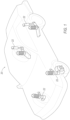
Figure 1 is a perspective view of a vehicle having a plurality of damper assemblies. -
Figure 2 is a cross-section of components of one of the damper assemblies, the components including a rod and a valve assembly. -
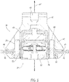
Figure 3 is a perspective view of the valve assembly disposed within an apparatus for applying torque. -
Figure 4 is cross-section view of the valve assembly disposed within the apparatus ofFigure 3 . -
Figure 5 is cross-section view of the valve assembly disposed within the apparatus ofFigure 3 . - An apparatus for applying torque to a body of a damper assembly includes a base defining an inner chamber. The apparatus includes a plurality of pins supported by base and disposed in the inner chamber. The plurality of pins are moveable relative to the base between engaged positions and disengaged positions. The apparatus includes a trigger actuatable to move at least one of the plurality of pins to the disengaged position.
- To apply torque to the body with the apparatus, an assembly is formed with the body disposed in the inner chamber of the base. The pins, in the engaged positions, are disposed in the plurality of openings. The pins, in the disengaged positions, are out of the openings. Movement of the pins between the engaged position and the disengaged position enables the apparatus to be easily engaged with the body to apply torque thereto to be easily disengaged from the body to separate the apparatus from the body, e.g., after application of torque.
- With reference to
Figure 1 , and wherein like numerals indicate like elements throughout the several views, avehicle 20 having a plurality ofdamper assemblies 22 is shown. Thevehicle 20 may be any suitable type of ground vehicle, e.g., a passenger or commercial automobile such as a sedan, a coupe, a truck, a sport utility, a crossover, a van, a minivan, a taxi, a bus, etc. - The
damper assemblies 22 are typically used in conjunction with automotive suspension systems or other suspension systems to control movement of wheels of thevehicle 20 relative to a body of thevehicle 20. In order to control movement,damper assemblies 22 are generally connected between the sprung (body) and the unsprung (suspension/drivetrain) masses of thevehicle 20. Eachdamper assembly 22 may be coupled with a coil spring. Eachdamper assembly 22 is movable from a compressed position to an extended position, and vice versa. A distance between ends of thedamper assembly 22, i.e., the distance from one end to the other end, is less in the compressed position than in the extended position. The coil springs, or the like, may urge the damper assemblies 22 toward the extended positions. Force applied to wheels of thevehicle 20, e.g., from bumps, potholes, etc., may urge to damperassemblies 22 toward the compressed position. - Each
damper assembly 22 controls movement of respective wheels by limiting fluid flow into, out of, and/or between various chambers of thedamper assembly 22, e.g., into, out of, and/or between a compression chamber and a rebound chamber, between a reserve chamber and the compression chamber and/or the rebound chamber, etc. Fluid movement is caused by movement of a piston within a pressure tube of thedamper assembly 22, e.g., when thedamper assembly 22 is moved toward the compressed position or the extended position. - Each
damper assembly 22 may include one or more valve assemblies that control fluid flow, e.g., through one or more passages connecting the rebound chamber, the compression chamber, and/or the reserve chamber. The valve assemblies may include springs, blow-off discs, restriction discs, etc. For example, and with reference toFigure 2 , a rodend valve assembly 24 is shown. The rodend valve assembly 24 is secured to an end of ahollow piston rod 26, e.g., controlling fluid flow into and out a passage of thepiston rod 26. - The rod
end valve assembly 24 includes ahousing body 28 and anend body 30. Thehousing body 28 and theend body 30 enclosevalve elements 32 that regulate fluid flow, e.g., in response to a change in fluid pressure or flow direction. Thevalve elements 32 disposed in thehousing body 28 may include, e.g., springs, valve discs, checks disc, or other suitable structure for regulating fluid flow. Thehousing body 28 may be generally cylindrical. Thehousing body 28 may threadedly engage theend body 30, e.g., via a first pair of engaged threads. Theend body 30 may threadedly engage thepiston rod 26, e.g., via a second pair of engaged threads. - The
housing body 28 defines a plurality ofopenings 34. Theopenings 34 may be between axially spaced ends of thehousing body 28. Theopenings 34 may be spaced from each other circumferentially about thehousing body 28, e.g., with equal spacing therebetween. Theopenings 34 may extend radially through thehousing body 28, e.g., from interior to exterior thehousing body 28. The terms axially, circumferentially, and radially used herein are relative to an axis A1, e.g., as shown inFigures 2-5 . - With reference to
Figs. 3-5 , anapparatus 36 for applying torque to thehousing body 28 is shown, e.g., to threading engage (i.e., tighten) and/or disengage (i.e., loosen) thehousing body 28 and theend body 30, and/or theend body 30 and thepiston rod 26. Theapparatus 36 applies torque to thehousing body 28, e.g., via application of force to theopenings 34. The torque applied by theapparatus 36 may be provided by, for example, a machine, a human with a wrench or other tool, etc. - The
apparatus 36 includes abase 38. Thebase 38 may have a generally frustoconical outer profile. Thebase 38 may have atop end 40 and abottom end 42 that is wider than thetop end 40. Thetop end 40 may be configured to engage with a torque application tool such as a wrench, driver, etc. For example, thetop end 40 may define arecession 44 or a protrusion of a certain shape, e.g., square, hexagonal, etc. In other words, thebase 38 may include structure to engage a socket wrench, a hex key, a square drive, etc. - The
base 38 defines aninner chamber 46. For example, thebase 38 may circumferentially surround theinner chamber 46. Thebase 38 may extend axially along an entirety of theinner chamber 46. Theinner chamber 46 may be open at thebottom end 42, e.g., permitting thehousing body 28 to be placed into, or removed from, theinner chamber 46. Theinner chamber 46 may be generally cylindrical, e.g., having a diameter and/or a length that are both greater than a diameter and/or a length of thehousing body 28. - The
base 38 may define one ormore passages 48. Each of thepassages 48 may extend from theinner chamber 46 to an outer surface of thebase 38. For example, thepassages 48 may extend radially outward frominner chamber 46 and entirely through thebase 38. Thepassages 48 may be between thetop end 40 and thebottom end 42 of thebase 38. Thepassages 48 may be spaced from each other circumferentially about thebase 38, e.g., with equal spacing therebetween. - The
apparatus 36 includes a plurality ofpins 50 supported by thebase 38. Thepins 50 selectively engage thehousing body 28, e.g., to apply torque thereto. Thepins 50 are disposed in theinner chamber 46 and movable relative to the base 38 between engaged positions and disengaged positions. The engaged positions may be radially inward of the disengaged positions. Thepins 50 in the engaged positions inhibit rotation of the base 38 relative to thehousing body 28. For example, thepins 50 in the engaged positions may be in the plurality ofopenings 34 of thehousing body 28. Thepins 50 in the engaged positions may extend from outside thehousing body 28 into theopenings 34. Thepins 50 in the engaged positions may transmit torque to thehousing body 28 via normal forces between thepins 50 and sides of theopenings 34. Thepins 50 in the disengaged positions permit rotation of the base 38 relative to thehousing body 28. Thepins 50 in the disengaged positions may be out of theopenings 34, e.g., spaced radially outward from thehousing body 28. - The
apparatus 36 may include one ormore cams 52. Thecams 52 provide movement of thepins 50 between the engaged positions and the disengaged positions. Thepins 50 and thecams 52 may be unitary. Unitary means a single, uniform piece of material with no seams, joints, fasteners, or adhesives holding it together, i.e., formed together simultaneously as a single continuous unit, e.g., by machining from a monolithic blank, molding, forging, casting, etc. Non-unitary components, in contrast, are formed separately and subsequently assembled, e.g., by threaded engagement, welding, etc. Each of thecams 52 may be elongated, e.g., circumferentially, between afirst end 54 and asecond end 56. Each of thepins 50 may be fixed to a respective one of thecams 52, e.g., to thefirst end 54 or thesecond end 56. Each of thecams 52 may be supported by, and pivotable relative to, thebase 38. For example, pivot pins 58 may connect thecams 52 to thebase 38. The pivot pins 58 may be disposed a hole. Thecams 52 may pivot about the pivot pins 58. Theapparatus 36 may include any other suitable structure to permit pivot of thecams 52 relative to thebase 38. Each of the pivot pins 58 may be between thefirst end 54 and thesecond end 56 of therespective cam 52. Pivoting thecam 52 about thepivot pin 58 may move thefirst end 54 ofsuch cam 52 radially inward and thesecond end 56 ofsuch cam 52 radially outward, and vice versa when thecam 52 is pivoted in an opposite direction. Eachpivot pin 58 may provide rotation about a respective second axis that is parallel to the axis A1. - One or more of the cams 52a may be positioned relative to the base 38 to move the
pins 50 attached thereto toward the engaged positions upon rotation of the base 38 in a first direction D1 and to move thepins 50 attached thereto toward the disengaged positions upon rotation of the base 38 in a second direction D2 opposite the first direction D1. For example, the first direction D1 may be clockwise and thepin 50 may be fixed to the cam 52a clockwise of thepivot pin 58. Normal forces betweensuch pin 50 thehousing body 28 may urge the cam 52a to pivot clockwise and urge thepin 50 toward thehousing body 28 upon rotation in the first direction D1. Normal forces betweensuch pin 50 and thehousing body 28 may urge the cam 52a to pivot counterclockwise and urge thepin 50 away from thehousing body 28 to the disengaged position upon rotation in the second direction D2, e.g., counterclockwise. For example, a distal end of thepin 50 may include an angled surface (not shown), such as a bevel or a chamfer, e.g., at a side of thepin 50 closest to therespective pivot pin 58. Normal forces between the angled surface and thehousing body 28 may urge thepin 50 out of theopening 34 to the disengaged position. - One or more other cams 52b may be positioned relative to the base 38 to move the
pins 50 attached thereto toward the engaged position upon rotation of the base 38 in the second direction D2 and to move thesecond pin 50 toward the disengaged position upon rotation of the base 38 in the first direction D1. For example, thepin 50 may be fixed to the cam 52b counterclockwise of thepivot pin 58. Normal forces betweensuch pin 50 and thehousing body 28 may urge the cam 52b to pivot counterclockwise and urge thepin 50 toward thehousing body 28 upon rotation in the second direction D2. Normal forces betweensuch pin 50 and thehousing body 28 may urge the cam 52b to pivot clockwise and urge thepin 50 away from thehousing body 28 to the disengaged position upon rotation in the first direction, e.g., clockwise. - Although shown as having
cams 52 oriented in multiple directions, theapparatus 36 may only includecams 52 positioned in one direction relative to thebase 38, e.g. such that thecams 52 and thepins 50 transfer torque to thehousing body 28 when theapparatus 36 is rotated in one direction, and not in the opposite direction. - The
apparatus 36 may include any other suitable structure for providing movement of thepins 50 between the engaged positions and the disengaged positions, e.g., in addition, or as an alternative, to thecams 52 and pivot pins 58. - The
apparatus 36 includes one ormore triggers 60 actuatable to move one or more of thepins 50 to the disengaged positions. For example, application of force on thetrigger 60, e.g., by a human, may move one or more of thepins 50 from the engaged positions to the disengaged positions. Application of force on thetrigger 60 may pivot thecam 52 about thepivot pin 58. Thetrigger 60 may be operatively coupled to thecam 52 to pivot thecam 52 upon actuation of thetrigger 60. For example, each of thecams 52 may have a respective one of thetriggers 60 fixed thereto, e.g., via fastener, threaded engagement, weld, etc. Thetriggers 60 may be disposed in thepassages 48 of thebase 38, e.g., with onetrigger 60 in each of thepassages 48. Thetrigger 60 may extend radially outward from thecams 52 through thepassages 48. Thetrigger 60 may extend away from theinner chamber 46 to beyond an outer surface of thebase 38. - The
apparatus 36 may include one ormore springs 62 that urge one or more of thepins 50 toward the engaged positions. Thesprings 62 may include elastically deformable material, such asspring 62 steel. Thesprings 62 may, for example, be coil compression springs 62. Thesprings 62 may include any suitable structure that provides resilient responsive force. Thesprings 62 may be supported by thebase 38. Thesprings 62 may be compressed between thecams 52 and thebase 38, e.g., between thefirst end 54 or thesecond end 56 and thebase 38. Thespring 62 may be at a same end as thepin 50. For example, thepin 50 and thespring 62 may both be at thefirst end 54 or thesecond end 56 of thecam 52. Thespring 62 may urge the respectivefirst end 54 orsecond end 56 of thecam 52, and thepin 50 attached thereto, radially inward. - The
apparatus 36 may include one ormore set screws 64, e.g., that control an amount of compression of thesprings 62. The set screws 64 may be supported by, and threading engaged with, thebase 38. Rotating theset screw 64 in a tightening direction may increase compression of thespring 62. For example, rotating theset screw 64 in the tightening direction may move theset screw 64 radially inward. The tightening direction may be, for example, clockwise. Rotation of theset screw 64 in a loosening direction may decrease compression of thespring 62. For example, rotating theset screw 64 in the loosening direction may move theset screw 64 radially outward. The loosening direction may be opposite the tightening direction, for example, counterclockwise. The set screws 64 may be supported by the base 38 at thecams 52, e.g., at the first ends 54 and/or the second ends 56. Theset screw 64 may be, for example, at the same end of thecam 52 as thespring 62. The set screws 64 may be circumferentially spaced from each other, e.g., around an outer perimeter of theinner chamber 46. The set screws 64 may abut thesprings 62. Moving theset screws 64 radially inward or outward may change an amount of space in which thesprings 62 is compressed between thecam 52 and the set screws 64. Thepassage 48 may be between theset screws 64, e.g., such that thetrigger 60 is circumferentially between a respective pair of theset screws 64 that are at thefirst end 54 andsecond end 56 of a respective one on thecams 52. Such configuration enables thecam 52 to be assembled to face one direction or an opposite direction, e.g., such that one of theset screws 64 of the pair can but used with thespring 62 when the cam 52a is facing one direction and that the other of theset screws 64 of the pair can but used with thespring 62 when the cam 52b is facing the opposite direction. - To apply torque with the
apparatus 36, thetriggers 60 may be actuated to move thepins 50 to the disengaged positions and thehousing body 28 may be inserted into theinner chamber 46. Thehousing body 28 disposed in theinner chamber 46 may be positioned relative to theapparatus 36 such that thepins 50 align with, and engage, theopenings 34. Torque may be applied to theapparatus 36 via thetop end 40, and transferred to thehousing body 28 via engagement of thepins 50 with theopenings 34. - In the drawings, the same reference numbers indicate the same elements. Further, some or all of these elements could be changed. With regard to the media, processes, systems, methods, etc. described herein, it should be understood that, although the steps of such processes, etc. have been described as occurring according to a certain ordered sequence, such processes could be practiced with the described steps performed in an order other than the order described herein. It further should be understood that certain steps could be performed simultaneously, that other steps could be added, or that certain steps described herein could be omitted. In other words, the descriptions of processes herein are provided for the purpose of illustrating certain embodiments, and should in no way be construed so as to limit the claimed invention.
- The disclosure has been described in an illustrative manner, and it is to be understood that the terminology which has been used is intended to be in the nature of words of description rather than of limitation. Many modifications and variations of the present disclosure are possible in light of the above teachings, and the disclosure may be practiced otherwise than as specifically described.
Claims (15)
- An apparatus for applying torque to a body, the apparatus comprising:a base defining an inner chamber;a plurality of pins supported by base and disposed in the inner chamber, the plurality of pins moveable relative to the base between engaged positions and disengaged positions; anda trigger actuatable to move at least one of the plurality of pins to the disengaged position.
- The apparatus of claim 1, wherein the pins in the engaged positions inhibit rotation of the base relative to the body and in the disengaged positions permit rotation of the base relative to the body.
- The apparatus of claim 1, further comprising a spring supported by the base and urging at least one of the plurality of pins toward the engaged position.
- The apparatus of claim 1, wherein the base defines a passage that extends from the inner chamber to an outer surface of the base, the trigger disposed in the passage.
- The apparatus of claim 1, further comprising a cam supported by and pivotable relative to the base, at least one of the plurality of pins fixed to the cam.
- The apparatus of claim 5, wherein the cam is positioned relative to the base to move the at least one of the plurality of pins toward the engaged position upon rotation of the base in a first direction and to move the at least one of the plurality of pins toward the disengaged position upon rotation of the base in a second direction opposite the first direction.
- The apparatus of claim 6, further comprising a second cam supported by and pivotable relative to the base, and further comprising a second pin of the plurality of pins fixed to the second cam, and wherein the second cam is positioned relative to the base to move the second pin toward the engaged position upon rotation of the base in the second direction and to move the second pin toward the disengaged position upon rotation of the base in the first direction.
- The apparatus of claim 5, wherein the trigger is operatively coupled to the cam to pivot the cam upon actuation of the trigger.
- The apparatus of claim 5, further comprising a spring compressed between the cam and the base.
- The apparatus of claim 9, further comprising a set screw supported by the base at the cam, rotation of the set screw in a tightening direction increases compression of the spring and rotation of the set screw in a loosening direction decreases compression of the spring.
- The apparatus of claim 10, further comprising a second set screw supported by the base at the cam, the second set screw circumferentially spaced from the set screw, and wherein the cam includes a first end, a second end, and a pivot therebetween, the set screw at the first end and the second set screw at the second end.
- The apparatus of claim 11, wherein the base defines a passage that extends from the inner chamber to an outer surface of the base, the passage is between the set screw and the second set screw, and the trigger is disposed in the passage.
- An assembly including the apparatus of any of claims 1-12, and further comprising a body disposed in the inner chamber and defining a plurality of openings, and wherein the plurality of pins in the engaged positions are in the plurality of openings and in the disengaged positions are out of the openings.
- The assembly of claim 13, further comprising a valve element disposed in the body.
- The assembly of claim 14, further comprising a hollow rod connected to the body.
Applications Claiming Priority (1)
| Application Number | Priority Date | Filing Date | Title |
|---|---|---|---|
| US17/463,867 US11806847B2 (en) | 2021-09-01 | 2021-09-01 | Torque application apparatus |
Publications (2)
| Publication Number | Publication Date |
|---|---|
| EP4144482A1 true EP4144482A1 (en) | 2023-03-08 |
| EP4144482B1 EP4144482B1 (en) | 2025-10-08 |
Family
ID=82939958
Family Applications (1)
| Application Number | Title | Priority Date | Filing Date |
|---|---|---|---|
| EP22190579.7A Active EP4144482B1 (en) | 2021-09-01 | 2022-08-16 | Torque application apparatus |
Country Status (3)
| Country | Link |
|---|---|
| US (1) | US11806847B2 (en) |
| EP (1) | EP4144482B1 (en) |
| CN (1) | CN115723097B (en) |
Citations (4)
| Publication number | Priority date | Publication date | Assignee | Title |
|---|---|---|---|---|
| US2774270A (en) * | 1955-03-07 | 1956-12-18 | Charles A Daniel | Pipe wrench |
| US4569257A (en) * | 1985-03-20 | 1986-02-11 | Hess Charles H | Collar unthreader |
| WO2005072173A2 (en) * | 2004-01-23 | 2005-08-11 | Loggerhead Tools Llc | Adjustable gripping tool |
| KR101014305B1 (en) * | 2003-10-27 | 2011-02-16 | 한국항공우주산업 주식회사 | Cylindrical part turning tool with movable pin |
Family Cites Families (45)
| Publication number | Priority date | Publication date | Assignee | Title |
|---|---|---|---|---|
| US760766A (en) * | 1903-11-30 | 1904-05-24 | Samuel A Swilley | Ratchet-wrench. |
| US3077801A (en) * | 1961-02-10 | 1963-02-19 | Irven O Rostad | Open end ratchet wrench |
| US3379286A (en) | 1966-03-30 | 1968-04-23 | Takagi Tatsuya | Oil damper |
| US3570635A (en) | 1967-12-11 | 1971-03-16 | Tatsuya Takagi | Oil-type vibration damper |
| US4604919A (en) * | 1984-12-06 | 1986-08-12 | Rollo Richard P | Open end ratchet socket wrench |
| JPH0524831Y2 (en) | 1986-02-20 | 1993-06-23 | ||
| US4874066A (en) | 1987-12-04 | 1989-10-17 | S.U.I. Corporation | Variable flow shock absorber and method |
| JPH0251637A (en) | 1988-08-12 | 1990-02-21 | Tokico Ltd | Damping force adjustable hydraulic shock absorber |
| US5058715A (en) | 1988-11-28 | 1991-10-22 | Ilan Silberstein | Shock absorber |
| GB2250080B (en) | 1990-10-19 | 1994-08-17 | Tokico Ltd | Hydraulic shock absorber |
| US5501244A (en) | 1994-11-14 | 1996-03-26 | Emhart Inc. | Valve assembly |
| US6220409B1 (en) | 1999-05-06 | 2001-04-24 | Tenneco Automotive Inc. | Stroke dependent bypass |
| JP3983027B2 (en) * | 2001-10-29 | 2007-09-26 | 株式会社空研 | Torque Wrench |
| DE10300107B3 (en) | 2003-01-07 | 2004-05-13 | Thyssenkrupp Bilstein Gmbh | Hydraulic shock absorber device has annular piston displaced within separate space connected hydraulically in parallel with damping piston |
| US6918473B2 (en) | 2003-09-17 | 2005-07-19 | Tenneco Automotive Operating Company Inc. | Stroke dependent bypass |
| US7213492B2 (en) * | 2004-10-29 | 2007-05-08 | Chen-Chang Tsai | Control mechanism for a socket wrench |
| DE102005055801B3 (en) | 2005-11-21 | 2007-02-15 | Thyssenkrupp Bilstein Suspension Gmbh | Vibration absorber for a motor vehicle's bodywork has an amplitude-selective absorbing device and pressure-limiting valves active in drawing and compression stages inside a bypass |
| US9010509B2 (en) * | 2006-12-15 | 2015-04-21 | Sp Air Kabushiki Kaisha | Ratchet drive for a ratchet wrench |
| DE102008060515B4 (en) | 2007-12-05 | 2015-08-06 | Mando Corporation | vibration |
| KR101272755B1 (en) | 2009-02-17 | 2013-06-10 | 주식회사 만도 | Shock absorber |
| JP2011064284A (en) | 2009-09-18 | 2011-03-31 | Kyb Co Ltd | Assembly tool |
| JP5466558B2 (en) | 2010-03-29 | 2014-04-09 | カヤバ工業株式会社 | Adjuster device, shock absorber provided with adjuster device |
| JP5859813B2 (en) | 2010-12-28 | 2016-02-16 | 日立オートモティブシステムズ株式会社 | Shock absorber |
| JP5783771B2 (en) | 2011-03-31 | 2015-09-24 | 日立オートモティブシステムズ株式会社 | Shock absorber |
| KR101254287B1 (en) | 2011-06-09 | 2013-04-12 | 주식회사 만도 | Valve structure having variable flow valve of a shock absorber |
| KR101288612B1 (en) | 2011-07-21 | 2013-07-22 | 주식회사 만도 | Valve structure of a shock absorber |
| JP5758235B2 (en) | 2011-08-31 | 2015-08-05 | 日立オートモティブシステムズ株式会社 | Shock absorber |
| JP5851159B2 (en) | 2011-08-31 | 2016-02-03 | 日立オートモティブシステムズ株式会社 | Shock absorber |
| JP5981800B2 (en) | 2012-08-03 | 2016-08-31 | Kyb株式会社 | Shock absorber |
| US8516927B1 (en) * | 2012-10-30 | 2013-08-27 | Yen-Hui Wang | Socket wrench with an energy-saving function |
| EP2977643B1 (en) | 2013-03-22 | 2018-09-26 | KYB Corporation | Shock absorber |
| JP5822359B2 (en) | 2013-03-27 | 2015-11-24 | Kyb株式会社 | Shock absorber |
| KR101426810B1 (en) | 2013-05-28 | 2014-08-05 | 주식회사 만도 | Frequency sensitive type shock absorber |
| US9239092B2 (en) | 2013-08-26 | 2016-01-19 | Tenneco Automotive Operating Company Inc. | Shock absorber with frequency dependent passive valve |
| JP6108550B2 (en) | 2013-09-19 | 2017-04-05 | Kyb株式会社 | Shock absorber |
| KR101798555B1 (en) | 2013-11-27 | 2017-11-16 | 주식회사 만도 | Shock abasorber |
| DE102013224724A1 (en) | 2013-12-03 | 2015-06-03 | Zf Friedrichshafen Ag | Vibration damper with selective damping |
| US11110570B2 (en) * | 2015-01-06 | 2021-09-07 | Earl Stuart Douglass | Reversible roller wrench with a scalloped outer race |
| JP2017048817A (en) | 2015-08-31 | 2017-03-09 | 日立オートモティブシステムズ株式会社 | Damping force adjustment type shock absorber |
| DE102016200935B4 (en) | 2016-01-22 | 2018-11-22 | Thyssenkrupp Ag | Vibration damper with frequency-dependent working valve arrangement |
| JP6681823B2 (en) | 2016-12-23 | 2020-04-15 | 日立オートモティブシステムズ株式会社 | Method for manufacturing shock absorber and crimping jig used in the method |
| US10625402B2 (en) * | 2017-07-24 | 2020-04-21 | Michael Thomas Jensen | Ratcheting spanner |
| JP6877286B2 (en) | 2017-07-26 | 2021-05-26 | 日立Astemo株式会社 | Damping force adjustment type shock absorber and its manufacturing method |
| US11346421B2 (en) | 2017-07-26 | 2022-05-31 | Hitachi Astemo, Ltd. | Damping force adjustable shock absorber |
| US10518601B2 (en) * | 2018-04-30 | 2019-12-31 | Tenneco Automotive Operating Company Inc. | Damper with internal hydraulic stop |
-
2021
- 2021-09-01 US US17/463,867 patent/US11806847B2/en active Active
-
2022
- 2022-08-01 CN CN202210914969.4A patent/CN115723097B/en active Active
- 2022-08-16 EP EP22190579.7A patent/EP4144482B1/en active Active
Patent Citations (4)
| Publication number | Priority date | Publication date | Assignee | Title |
|---|---|---|---|---|
| US2774270A (en) * | 1955-03-07 | 1956-12-18 | Charles A Daniel | Pipe wrench |
| US4569257A (en) * | 1985-03-20 | 1986-02-11 | Hess Charles H | Collar unthreader |
| KR101014305B1 (en) * | 2003-10-27 | 2011-02-16 | 한국항공우주산업 주식회사 | Cylindrical part turning tool with movable pin |
| WO2005072173A2 (en) * | 2004-01-23 | 2005-08-11 | Loggerhead Tools Llc | Adjustable gripping tool |
Also Published As
| Publication number | Publication date |
|---|---|
| US20230061313A1 (en) | 2023-03-02 |
| US11806847B2 (en) | 2023-11-07 |
| EP4144482B1 (en) | 2025-10-08 |
| CN115723097A (en) | 2023-03-03 |
| CN115723097B (en) | 2026-01-06 |
Similar Documents
| Publication | Publication Date | Title |
|---|---|---|
| US9809075B2 (en) | Gas spring and gas damper assembly and method | |
| US4830395A (en) | Stabilizer system for racing cars | |
| US5584226A (en) | Hydraulically supported power steering system | |
| US10161471B2 (en) | Suspension systems and methods of operating same | |
| CN113661342B (en) | Preassembled piston accumulator arrangement | |
| US20200376911A1 (en) | Gas spring end member assemblies as well as gas spring assemblies including same | |
| US11554624B2 (en) | Gas spring and gas damper assemblies as well as suspension systems and methods including the same | |
| US8950764B2 (en) | Jounce bumper, end member, gas spring assembly and method of assembly | |
| EP4144482A1 (en) | Torque application apparatus | |
| CA3055576C (en) | Caliper for a disc brake configured to facilitate attachment of a brake actuator | |
| US5518090A (en) | Piston post for a damper | |
| EP0825043B1 (en) | Pressure-regulating device and suspension apparatus | |
| US8950765B2 (en) | Mounting bracket assembly for vehicle suspension component as well as suspension assembly, kit and method including same | |
| CN103089896B (en) | Connecting method and cylinder apparatus | |
| EP4119249A1 (en) | Roller press assembly and method | |
| US12350986B2 (en) | Flexible spring member and end closure assemblies as well as gas spring and gas damper assemblies including same | |
| WO2022212609A1 (en) | End member assemblies as well as gas spring and damper assemblies including same | |
| US11802604B2 (en) | Gas spring and damper assemblies as well as suspension systems including same | |
| US20220049754A1 (en) | Damper assembly | |
| JP2942621B2 (en) | Hydraulic shock absorber valve structure | |
| US12188492B1 (en) | Method of charging a bellows accumulator | |
| US9387741B2 (en) | Elastomeric thermal barrier as well as gas spring assembly and suspension system including same | |
| KR20220115877A (en) | Modular screw as well as method for producing a modular screw |
Legal Events
| Date | Code | Title | Description |
|---|---|---|---|
| PUAI | Public reference made under article 153(3) epc to a published international application that has entered the european phase |
Free format text: ORIGINAL CODE: 0009012 |
|
| STAA | Information on the status of an ep patent application or granted ep patent |
Free format text: STATUS: REQUEST FOR EXAMINATION WAS MADE |
|
| 17P | Request for examination filed |
Effective date: 20220816 |
|
| AK | Designated contracting states |
Kind code of ref document: A1 Designated state(s): AL AT BE BG CH CY CZ DE DK EE ES FI FR GB GR HR HU IE IS IT LI LT LU LV MC MK MT NL NO PL PT RO RS SE SI SK SM TR |
|
| P01 | Opt-out of the competence of the unified patent court (upc) registered |
Effective date: 20230528 |
|
| GRAP | Despatch of communication of intention to grant a patent |
Free format text: ORIGINAL CODE: EPIDOSNIGR1 |
|
| STAA | Information on the status of an ep patent application or granted ep patent |
Free format text: STATUS: GRANT OF PATENT IS INTENDED |
|
| INTG | Intention to grant announced |
Effective date: 20250502 |
|
| RAP1 | Party data changed (applicant data changed or rights of an application transferred) |
Owner name: ADVANCED SUSPENSION TECHNOLOGY LLC |
|
| GRAS | Grant fee paid |
Free format text: ORIGINAL CODE: EPIDOSNIGR3 |
|
| GRAA | (expected) grant |
Free format text: ORIGINAL CODE: 0009210 |
|
| STAA | Information on the status of an ep patent application or granted ep patent |
Free format text: STATUS: THE PATENT HAS BEEN GRANTED |
|
| AK | Designated contracting states |
Kind code of ref document: B1 Designated state(s): AL AT BE BG CH CY CZ DE DK EE ES FI FR GB GR HR HU IE IS IT LI LT LU LV MC MK MT NL NO PL PT RO RS SE SI SK SM TR |
|
| REG | Reference to a national code |
Ref country code: GB Ref legal event code: FG4D Ref country code: CH Ref legal event code: F10 Free format text: ST27 STATUS EVENT CODE: U-0-0-F10-F00 (AS PROVIDED BY THE NATIONAL OFFICE) Effective date: 20251008 |
|
| REG | Reference to a national code |
Ref country code: DE Ref legal event code: R096 Ref document number: 602022022592 Country of ref document: DE |
|
| REG | Reference to a national code |
Ref country code: IE Ref legal event code: FG4D |
|
| REG | Reference to a national code |
Ref country code: NL Ref legal event code: MP Effective date: 20251008 |
|
| REG | Reference to a national code |
Ref country code: AT Ref legal event code: MK05 Ref document number: 1844459 Country of ref document: AT Kind code of ref document: T Effective date: 20251008 |
|
| PG25 | Lapsed in a contracting state [announced via postgrant information from national office to epo] |
Ref country code: NL Free format text: LAPSE BECAUSE OF FAILURE TO SUBMIT A TRANSLATION OF THE DESCRIPTION OR TO PAY THE FEE WITHIN THE PRESCRIBED TIME-LIMIT Effective date: 20251008 |
|
| REG | Reference to a national code |
Ref country code: CH Ref legal event code: W10 Free format text: ST27 STATUS EVENT CODE: U-0-0-W10-W00 (AS PROVIDED BY THE NATIONAL OFFICE) Effective date: 20260402 |
|
| PG25 | Lapsed in a contracting state [announced via postgrant information from national office to epo] |
Ref country code: ES Free format text: LAPSE BECAUSE OF FAILURE TO SUBMIT A TRANSLATION OF THE DESCRIPTION OR TO PAY THE FEE WITHIN THE PRESCRIBED TIME-LIMIT Effective date: 20251008 |
|
| REG | Reference to a national code |
Ref country code: LT Ref legal event code: MG9D |
|
| PG25 | Lapsed in a contracting state [announced via postgrant information from national office to epo] |
Ref country code: NO Free format text: LAPSE BECAUSE OF FAILURE TO SUBMIT A TRANSLATION OF THE DESCRIPTION OR TO PAY THE FEE WITHIN THE PRESCRIBED TIME-LIMIT Effective date: 20260108 |
|
| PG25 | Lapsed in a contracting state [announced via postgrant information from national office to epo] |
Ref country code: AT Free format text: LAPSE BECAUSE OF FAILURE TO SUBMIT A TRANSLATION OF THE DESCRIPTION OR TO PAY THE FEE WITHIN THE PRESCRIBED TIME-LIMIT Effective date: 20251008 Ref country code: HR Free format text: LAPSE BECAUSE OF FAILURE TO SUBMIT A TRANSLATION OF THE DESCRIPTION OR TO PAY THE FEE WITHIN THE PRESCRIBED TIME-LIMIT Effective date: 20251008 Ref country code: FI Free format text: LAPSE BECAUSE OF FAILURE TO SUBMIT A TRANSLATION OF THE DESCRIPTION OR TO PAY THE FEE WITHIN THE PRESCRIBED TIME-LIMIT Effective date: 20251008 |
|
| PG25 | Lapsed in a contracting state [announced via postgrant information from national office to epo] |
Ref country code: RS Free format text: LAPSE BECAUSE OF FAILURE TO SUBMIT A TRANSLATION OF THE DESCRIPTION OR TO PAY THE FEE WITHIN THE PRESCRIBED TIME-LIMIT Effective date: 20260108 |
|
| PG25 | Lapsed in a contracting state [announced via postgrant information from national office to epo] |
Ref country code: IS Free format text: LAPSE BECAUSE OF FAILURE TO SUBMIT A TRANSLATION OF THE DESCRIPTION OR TO PAY THE FEE WITHIN THE PRESCRIBED TIME-LIMIT Effective date: 20260208 |
|
| PG25 | Lapsed in a contracting state [announced via postgrant information from national office to epo] |
Ref country code: PT Free format text: LAPSE BECAUSE OF FAILURE TO SUBMIT A TRANSLATION OF THE DESCRIPTION OR TO PAY THE FEE WITHIN THE PRESCRIBED TIME-LIMIT Effective date: 20260209 |
|
| PG25 | Lapsed in a contracting state [announced via postgrant information from national office to epo] |
Ref country code: LV Free format text: LAPSE BECAUSE OF FAILURE TO SUBMIT A TRANSLATION OF THE DESCRIPTION OR TO PAY THE FEE WITHIN THE PRESCRIBED TIME-LIMIT Effective date: 20251008 |
|
| RAP4 | Party data changed (patent owner data changed or rights of a patent transferred) |
Owner name: ADVANCED SUSPENSION TECHNOLOGY LLC |