EP4143640B1 - Uhrwerk, das einen chronographenmechanismus mit countdown-funktion und einen schlagwerkmechanismus umfasst - Google Patents
Uhrwerk, das einen chronographenmechanismus mit countdown-funktion und einen schlagwerkmechanismus umfasst Download PDFInfo
- Publication number
- EP4143640B1 EP4143640B1 EP21721113.5A EP21721113A EP4143640B1 EP 4143640 B1 EP4143640 B1 EP 4143640B1 EP 21721113 A EP21721113 A EP 21721113A EP 4143640 B1 EP4143640 B1 EP 4143640B1
- Authority
- EP
- European Patent Office
- Prior art keywords
- striking
- countdown
- cam
- tens
- minutes
- Prior art date
- Legal status (The legal status is an assumption and is not a legal conclusion. Google has not performed a legal analysis and makes no representation as to the accuracy of the status listed.)
- Active
Links
Images


Classifications
-
- G—PHYSICS
- G04—HOROLOGY
- G04F—TIME-INTERVAL MEASURING
- G04F3/00—Apparatus which can be set and started to measure-off predetermined or adjustably-fixed time intervals with driving mechanisms, e.g. dosimeters with clockwork
- G04F3/02—Apparatus which can be set and started to measure-off predetermined or adjustably-fixed time intervals with driving mechanisms, e.g. dosimeters with clockwork with mechanical driving mechanisms
- G04F3/022—Apparatus which can be set and started to measure-off predetermined or adjustably-fixed time intervals with driving mechanisms, e.g. dosimeters with clockwork with mechanical driving mechanisms using mechanical signalling device
-
- G—PHYSICS
- G04—HOROLOGY
- G04B—MECHANICALLY-DRIVEN CLOCKS OR WATCHES; MECHANICAL PARTS OF CLOCKS OR WATCHES IN GENERAL; TIME PIECES USING THE POSITION OF THE SUN, MOON OR STARS
- G04B23/00—Arrangements producing acoustic signals at preselected times
-
- G—PHYSICS
- G04—HOROLOGY
- G04B—MECHANICALLY-DRIVEN CLOCKS OR WATCHES; MECHANICAL PARTS OF CLOCKS OR WATCHES IN GENERAL; TIME PIECES USING THE POSITION OF THE SUN, MOON OR STARS
- G04B23/00—Arrangements producing acoustic signals at preselected times
- G04B23/02—Alarm clocks
- G04B23/12—Alarm watches to be worn in pockets or on the wrist
-
- G—PHYSICS
- G04—HOROLOGY
- G04F—TIME-INTERVAL MEASURING
- G04F7/00—Apparatus for measuring unknown time intervals by non-electric means
- G04F7/04—Apparatus for measuring unknown time intervals by non-electric means using a mechanical oscillator
- G04F7/08—Watches or clocks with stop devices, e.g. chronograph
- G04F7/0866—Special arrangements
Definitions
- the present invention relates to a mechanical watch movement comprising a chronograph mechanism arranged to be able to carry out at least one countdown of a predetermined time interval, comprising display means arranged to display at least the time remaining until the end of the countdown of said time interval, at least one member for controlling the start of the countdown, and a striking mechanism.
- a countdown mechanism with a chime is provided, allowing the countdown of a predetermined time duration, adjustable up to 11:55 in five-minute jumps.
- a control activated by a push-button, is used to start the countdown. The end of the countdown is indicated by a mechanical chime. The remaining time is indicated by two discs indicating the hours and minutes.
- the document US1153466A describes a countdown mechanism capable of bringing a bell into the vibration zone of a hammer to sound an alarm towards the expiration of a predetermined period of time.
- the present invention aims to provide an improved mechanical clock movement compared to known striking countdown mechanisms.
- the present invention relates to a mechanical watch movement comprising a chronograph mechanism arranged to be able to carry out at least one countdown of a predetermined time interval, comprising display means arranged to display at least the time remaining until the end of the countdown of said predetermined time interval, at least one member for controlling the start of the countdown, and a striking mechanism.
- said striking mechanism is arranged to start striking at a determined duration before the end of the countdown and to finish striking with the end of said countdown at said predetermined time interval.
- the invention makes it possible to trigger a striking mechanism before the end of the countdown of said predetermined time interval in order to prevent a user that the current countdown of the predetermined time interval is about to end.
- the present invention makes it possible to have a countdown of a predetermined time interval having a pre-alarm using a mechanical bell, and to be able to synchronize the end of the bell with the end of the countdown of said predetermined time interval.
- the chronograph mechanism comprises at least one chronograph drive wheel set arranged to be able to carry out a countdown, and in particular the countdown of the predetermined time interval and the striking mechanism comprises at least one first cam kinematically linked to said chronograph drive wheel set and on which is programmed said determined duration before the end of the countdown of said predetermined time interval, said first cam being arranged to make one revolution over a duration greater than the determined duration before the end of the countdown of said predetermined time interval, a striking train, a first striking lever comprising a first striking feeler lever arranged to be able to cooperate with said first cam and said striking train to trigger the striking at the start of the determined duration before the end of the countdown of said predetermined time interval and a striking end mechanism arranged to be able to cooperate with said first striking lever to control the stopping of the striking at the end of said determined duration at the same time as the end of the countdown of said predetermined time interval. predetermined time.
- the display means of the chronograph mechanism may comprise a first display member associated with the first cam to display a countdown obtained via the chronograph drive mobile.
- the first display member is arranged to display a countdown of units of minutes.
- the first display member is arranged to display a countdown of seconds.
- the display means of the chronograph mechanism may comprise a second minute unit display member arranged to display the countdown of the minute units of said predetermined time interval and the striking mechanism comprises a second minute unit cam associated with said second minute unit display member, and a third minute unit feeler lever arranged to be able to cooperate with said second minute unit cam, said second minute unit cam being programmed to indicate to the third minute unit feeler lever the end of the minute unit countdown, said third minute unit feeler lever being arranged to cooperate with the first striking feeler lever so that said first striking feeler lever comes to cooperate with the first cam at the end of the minute unit countdown.
- the display means of the chronograph mechanism may comprise a third tens-of-minute display member arranged to display the tens-of-minute countdown of said predetermined time interval and the striking mechanism comprises a third tens-of-minute cam associated with said third tens-of-minute display member, and a fourth tens-of-minute feeler lever arranged to be able to cooperate with said third tens-of-minute cam, said third tens-of-minute cam being programmed to indicate to the fourth tens-of-minute feeler lever the end of the tens-of-minute countdown, said fourth tens-of-minute feeler lever being arranged to cooperate with the third minute unit feeler lever so that said third minute unit feeler lever cooperates with said second minute unit cam at the end of the tens-of-minute countdown.
- the display means of the chronograph mechanism may comprise a third tens display member of minutes arranged to display the countdown of tens of minutes of said predetermined time interval and the striking mechanism comprises a third tens of minutes cam associated with said third tens of minutes display member, and a fourth tens of minutes feeler lever arranged to be able to cooperate with said third tens of minutes cam, said third tens of minutes cam being programmed to indicate to the fourth tens of minutes feeler lever the end of the tens of minutes countdown, said fourth tens of minutes feeler lever being arranged to cooperate with the first striking feeler lever so that said first striking feeler lever comes to cooperate with said first cam at the end of the tens of minutes countdown.
- the display means of the chronograph mechanism may comprise a fourth hour display member arranged to display the countdown of the hours of said predetermined time interval and the striking mechanism comprises a fourth hour cam associated with said fourth hour display member, and a fifth hour feeler lever arranged to be able to cooperate with said fourth hour cam, said fourth hour cam being programmed to indicate to the fifth hour feeler lever the end of the hour countdown, said fifth hour feeler lever being arranged to cooperate with the fourth tens-minute feeler lever so that said fourth tens-minute feeler lever comes to cooperate with said third tens-minute cam at the end of the hour countdown.
- the third minute unit feeler lever, the fourth tens of minutes feeler lever and the fifth hours feeler lever can form a single lever, possibly also with the first striking feeler lever.
- the chronograph mechanism is configured to be kinematically connectable to a base movement by a lateral or vertical clutch device.
- the end-of-strike mechanism comprises an end-of-strike lever comprising a second end-of-strike feeler lever arranged to be able to cooperate with the first cam to control disengagement of the clutch device and stopping of the strike, at the end of the countdown of said predetermined time interval.
- the chronograph mechanism stops automatically with the end of the countdown of the predetermined time interval.
- the end-of-strike mechanism comprises an end-of-strike lever arranged to cooperate with the first strike lever and a strike stop cam kinematically linked to said chronograph drive wheel and arranged to control the end-of-strike lever in order to stop the strike at the end of the countdown of said predetermined time interval without disengaging the clutch device.
- the chronograph mechanism and more particularly its chronograph drive wheel set, remains activated after the end of the countdown of the predetermined time interval.
- the first display organ and more particularly the chronograph second hand, continues to rotate without triggering a chime.
- a manual stop by a user will be necessary to stop the chronograph mechanism.
- the present invention relates to a mechanical watch movement comprising a chronograph mechanism arranged to be able to perform at least one countdown of a predetermined time interval.
- chronograph mechanism should be considered in the broad sense of the term, that is to say as comprising all the necessary elements or components arranged to produce at least one countdown of time and fraction of time to perform at least one countdown.
- the chronograph mechanism is represented here schematically by a chronograph drive wheel 1, a drive wheel 2 making one revolution per minute, corresponding to a chronograph seconds wheel, said drive wheel 2 being arranged to cooperate with the other components of the chronograph to be able to carry out a countdown, and in particular a countdown of a predetermined time interval.
- the chronograph mechanism, and more particularly the chronograph drive wheel 1, is arranged to be able to be kinematically connected to the second wheel 4 of a basic watch movement indicating the current time by a vertical clutch device 6.
- Said vertical clutch device 6 comprises a clutch control clamp 8 and a clutch clamp 10 arranged to move apart when the chronograph is activated to start a countdown, so as to engage the second wheel 4 and the chronograph drive wheel 1 allowing energy from the basic movement to be transmitted to the chronograph mechanism for its operation.
- the chronograph mechanism also comprises a control member 11 for starting the countdown arranged to control at least the triggering of the chronograph mechanism, and in particular the opening of the clamps 8 and 10, by means of a control device 12 comprising a column wheel 14.
- This control member 11 is for example a pusher. It can be arranged to also control the stopping of the chronograph mechanism, and in particular the closing of the clamps 8 and 10, during the countdown if necessary.
- the chronograph mechanism is arranged to be stopped automatically at the same time as the striking mechanism.
- control device 12 advantageously comprises a main control 13 actuable by the control member 11, and a secondary control 15 pivotally mounted on the main control 13 and to which it is connected by an elastic member (not shown).
- the main 13 and secondary 15 controls are respectively terminated by a hook 13a, 15a.
- the column wheel 14 comprises a first drive wheel 14a secured to the columns 14b and arranged to be actuated by the hook 15a of the secondary control 15, and a second drive wheel 14c arranged to be actuated by the hook 13a of the main control 13.
- the control device 12 also comprises a mechanism for locking the secondary control 15 in rotation on the main control 13 arranged to be able to be controlled manually by the control member 11 as well as internally, automatically, by an internal control member, here the hook 56 of the end-of-strike lever 50 as will be described below.
- the locking mechanism and the secondary control 15 are arranged to occupy a locked state in which the elastic member connecting the main control 13 and secondary control 15 is armed and the secondary control 15 is rotationally integral with the main control 13 allowing, upon actuation of the main control 13 via the actuation member 11, to actuate the column wheel 14 simultaneously by the main control 13 and secondary control 15, and to be able to pass, in the event of actuation of the locking mechanism by the hook 56, into an unlocked state in which said secondary control 15 is detached from the main control 13 and actuates, alone, the column wheel 14, the elastic member being disarmed, and to pass through a locking position, by actuation of the main control 13, in which only the main control 13 actuates the column wheel 14, said main control 13 being arranged to rearm the elastic member and cooperate with the secondary control locking mechanism 15 to return to the locked state.
- the second drive wheel 14c is connected to the first drive wheel 14a by an elastic coupling element (not shown) arranged to connect the second drive wheel 14c to the first drive wheel 14a in rotation when only the second drive wheel 14c is actuated by the hook 13a of the main control 13 if the secondary control 15 has moved to the unlocked state and then only the main control 13 is actuated during the next manual actuation via the control member 11, and to detach the second drive wheel 14c from the first drive wheel 14a when only the first drive wheel 14a is actuated, thanks to the energy supplied by the elastic member which is disarmed, by the secondary control 15, after having been detached from the main control 13.
- This device for controlling the chronograph mechanism can be operated by a user, but also by an internal control linked to the striking mechanism, so as to have an automatic control, in addition to a manual control of said chronograph mechanism, to stop the chronograph mechanism at the same time as the striking mechanism.
- the chronograph mechanism also comprises display means arranged to display at least the time remaining until the end of the countdown of the predetermined time interval.
- these display means comprise a first display member for displaying a countdown of seconds, and in particular the countdown of seconds of the predetermined time interval, a second display member for displaying the countdown of units of minutes of the predetermined time interval, a third display member for displaying the countdown of tens of minutes of the predetermined time interval and a fourth display member for displaying the countdown of hours of the predetermined time interval.
- These display means may be discs, hands, rollers or any other display member suitable for displaying the count of hours, tens and units of minutes, as well as seconds.
- the first seconds display member is a hand (not shown) corresponding to the second hand.
- FIG 11 represents a preferred embodiment of the display members for displaying the countdown of hours, tens and units of minutes of the predetermined time interval, used in the present invention in the form of discs, the first seconds display member being a hand (not shown), corresponding to the second hand. More specifically, the second display member for counting the units of minutes of the predetermined time interval is a disc 16 bearing the numbers 0 to 9 regularly distributed around its periphery, said disc 16 being arranged to make one revolution in ten minutes.
- the third display member for counting the tens of minutes of the predetermined time interval is a disc 18 arranged tangentially to the disc of the units of minutes 16.
- the disc of the tens of minutes 18 bears two consecutive series of numbers 0 to 5 regularly distributed around its periphery, said disc 18 being arranged to make one revolution in two hours.
- the fourth display member for counting the hours of the predetermined time interval is a disc 20, arranged concentrically inside the disc of the tens of minutes 18.
- the disc of the hours 20 bears a series of numbers 0 to 6 regularly distributed around its periphery, said disc 20 being arranged to make one revolution in seven hours.
- the centers of the three discs 16, 18 and 20 are aligned allowing a display of the countdown of hours, tens of minutes and units of minutes of the predetermined time interval in juxtaposed windows for easy reading of the countdown.
- the various display members can be arranged to drive one after the other from the second to the hour, starting for example from the drive wheel 2.
- the first display member for displaying the countdown of the seconds can be kinematically linked to the drive wheel 2 and an auxiliary energy source can be provided to supply energy to the display member for counting the units of minutes, which drives the display member for counting the tens of minutes, itself driving the display member for counting the hours, for example by means of operating fingers and stars cooperating to make the display organ jump corresponding to each change of ten minutes or hours.
- An adjustment mechanism (not shown) is provided for positioning, before the start of the countdown of the predetermined time interval, the various display members for counting down the hours 20, the tens of minutes 18 and the units of minutes 16 so as to display the predetermined time interval to be counted down, said time interval to be counted down being adjustable for example up to 6H59.
- the various display members are arranged to display the remaining time which decreases as the countdown progresses, from the value of the predetermined time interval to 0h00min00s, in a very precise manner, to the nearest second.
- the mechanical movement according to the invention also comprises a striking mechanism made up of mechanical components, and comprising in particular a striking train, represented here by an element 30 of the striking train carrying a stop star 32 of the striking train.
- a striking mechanism made up of mechanical components, and comprising in particular a striking train, represented here by an element 30 of the striking train carrying a stop star 32 of the striking train.
- the striking mechanism is arranged so that the striking mechanism begins to sound at a determined duration before the end of the countdown of the predetermined time interval, and ends to sound with the end of the countdown, that is to say at the same time as the countdown of said predetermined time interval reaches 0h00min00s.
- the striking mechanism comprises at least a first cam 34 kinematically linked to the chronograph drive wheel set 1 and on which is programmed said determined duration before the end of the countdown of said predetermined time interval, said first cam 34 being arranged to make one revolution over a duration greater than the determined duration before the end of the countdown of said predetermined time interval.
- the first cam 34 is associated with the first display member to display at least the countdown of said predetermined time interval obtained via the chronograph drive wheel set 1.
- the first cam 34 is the seconds cam, associated with the first display member (i.e. the second hand) to display a countdown of the seconds. The first cam 34 therefore makes one revolution per minute here.
- the first cam 34 has an essentially circular profile and comprises a notch 36 whose circular length corresponds to the determined duration of the strike before the end of the countdown of the predetermined time interval, the start 36a of the notch 36 corresponding to the triggering of the strike, and the end 36b of the notch 36 corresponding to the stopping of the strike, at the same time as the stopping of the countdown of said predetermined time interval, as will be described in detail below.
- the length of the notch 36, between the start 36a and the end 36b of said notch 36 may correspond to a duration of 20 seconds before the end of the countdown of said predetermined time interval.
- the striking mechanism also comprises a first striking lever comprising a first striking feeler lever 38 arranged to be able to cooperate with the first cam 34 and the striking train to trigger the striking at the start of the determined duration before the end of the countdown of said predetermined time interval.
- the striking mechanism also comprises a strike end mechanism arranged to be able to cooperate with said first striking lever. to control the stopping of the bell at the end of said determined duration at the same time as the end of the countdown of said predetermined time interval.
- the first second cam 34 is carried by the drive wheel 2 which meshes with the chronograph drive wheel set 1.
- the first strike feeler lever 38 constitutes the first arm of a strike lever 41 pivotally mounted at A.
- the first strike feeler lever 38 has a beak 38a arranged to be able to come into contact with the first second cam 34 and then engage in its notch 36 at the time of striking, as will be described in more detail below.
- Said striking lever 41 comprises a second arm 42 arranged to control a striking stop lever 44 pivotally mounted in D, a pin 43 secured to the second arm 42 ensuring the connection with said lever 44 via an oblong opening 45, said striking stop lever 44 itself being arranged to be able to cooperate with the stop star 32 of the striking train.
- the striking lever 41 comprises a third arm 46 comprising a heel 46a arranged to be able to cooperate with a pin 48 carried by the clutch clamp 10.
- the end-of-strike mechanism comprises an end-of-strike lever 50 pivotally mounted at B and provided with a second end-of-strike feeler lever 40 arranged to be able to cooperate with the first cam 34 to control the stopping of the strike at the end of said determined duration at the same time as the end of the countdown of said predetermined time interval.
- the first cam 34 provided with its notch 36 is also part of the end-of-strike mechanism and constitutes both a start-of-strike cam and a stop-of-strike cam.
- the second end-of-strike feeler lever 40 constitutes the first arm of the end-of-strike lever 50.
- the second end-of-strike feeler lever 40 has a beak 40a arranged to be able to come into contact with the first second cam 34 when the first strike feeler lever 38 falls into the notch 36 of said first cam 34 to trigger the strike, and to engage in said notch 36 at the end of the countdown and the strike, as will be described in more detail below.
- the end-of-strike lever 50 comprises a second arm 54 carrying at its free end a hook 56 pivotally mounted in C and held in position by a pin 58 carried by the end of said second arm 54.
- the pivoting hook 56 is arranged to cooperate with the control device 12, as will be described below.
- the second end-of-strike feeler lever 40 is arranged to control, by means of said hook 56, a disengagement of the clutch device 6 and the stopping of the strike when said second end-of-strike feeler lever 40 falls into the notch 36 at the end of the countdown.
- the end-of-strike lever 50 also comprises a third arm 60, in the extension of the second end-of-strike feeler lever 40.
- Said third arm 60 comprises a first beak 60a arranged to be able to cooperate with the foot 46b of the third arm 46 of the strike lever 41 and a second beak 60b arranged to be able to cooperate with the pin 48 of the clutch clamp 10.
- the third minute unit feeler lever 64 is arranged to cooperate with the first strike feeler lever 38 so that said first strike feeler lever 38 comes into contact with the first second cam 34 at the end of the minute unit count, when the hour, tens of minutes and minute unit display members all display 0.
- the third feeler lever of the minute units 64 is a first arm of a detection lever 68 pivotally mounted at A, like the striking lever 41.
- the detection lever 68 and the striking lever 41 are arranged to be able to cooperate with each other.
- the detection lever 68 comprises, on said third minute unit feeler lever 64, a pin 70 arranged to be in contact with the striking lever 41, and for example with its third arm 46, so that a pivoting at A of one of the detection levers 68 and striking levers 41 causes a pivoting at A of the other of the detection levers 68 and striking levers 41.
- a pivoting at A of the detection lever 68 in the counterclockwise direction moves the pin 70 away from the striking lever 41 so that said striking lever 41, released, can pivot in turn in the counterclockwise direction.
- the striking mechanism also comprises a third tens of minutes cam 72 associated with the third tens of minutes display member 18, and a fourth tens of minutes feeler lever 74 arranged to be able to cooperate with said third tens of minutes cam 72, said third tens of minutes cam 72 being programmed to indicate to the fourth tens of minutes feeler lever 74 the end of the tens of minutes countdown.
- the tens of minutes cam 72 has an essentially circular profile and may comprise, for example, two opposite notches 76, when the third tens of minutes display member 18 is arranged to make one revolution, with the tens of minutes cam 72, in two hours.
- the tens of minutes cam 72 may comprise a single notch 76 if the third tens of minutes display member is arranged to make one revolution per hour.
- the fourth tens of minutes feeler lever 74 is arranged to position itself in one of the notches 76 when the hour 20 and tens of minutes 18 display members both display 0, that is to say from the moment when there are less than ten minutes remaining to countdown.
- the fourth tens-of-minute feeler lever 74 is arranged to cooperate with the third units-of-minute feeler lever 64 so that said third units-of-minute feeler lever 64 cooperates with the second units-of-minute cam 62 at the end of the tens-of-minute countdown, when the hour 20 and tens-of-minute 18 display members both display 0.
- the striking mechanism also includes a fourth hour cam 78 associated with the fourth hour display organ 20, superimposed on the third tens of minutes cam 72, and a fifth feeler lever hours 80, superimposed on the fourth tens of minutes feeler lever 74, and arranged to be able to cooperate with said fourth hours cam 78, said fourth hours cam 78 being programmed to indicate to the fifth hours feeler lever 80 the end of the hours count.
- the fourth hours cam 78 has an essentially circular profile and includes a notch 82 (cf. Figures 4 and 5 ), the fifth hour feeler lever 80 being arranged to position itself in the notch 82 when the hour display member 20 displays 0, that is to say from the moment when there is less than one hour left to count down.
- the fourth hour display member 20 may be arranged to rotate with the fourth hour cam 78, so as to allow a countdown of six hours per revolution.
- the number of hours counted may be different depending on the arrangement of the hour display member 20.
- the fifth hour feeler lever 80 is arranged to cooperate with the fourth tens of minutes feeler lever 74 so that said fourth tens of minutes feeler lever 74 cooperates with the third tens of minutes cam 72 at the end of the hour count, when the hour display member 20 displays 0.
- the fifth feeler lever of the hours 80 is a third arm of the detection lever 68, so that a pivoting at A in the counterclockwise direction of the fifth feeler lever of the hours 80, falling into the notch 82 of the cam of the hours 78, causes a pivoting at A, in the counterclockwise direction, of the fourth feeler lever of the tens of minutes 74 to come into contact with the cam of the tens of minutes 72.
- the starting STOP position is shown on the Figure 1 , in which the control device 12 is ready for operation.
- the secondary control 15 and the locking mechanism are in the locked state, the locking hook 22 being coupled to the hook 15b of the secondary control 15.
- the secondary control 15 is therefore locked in rotation with the main control 13, the elastic member connecting them being armed.
- the countdown chronograph mechanism and the striking mechanism are inactive. It is considered that the various display members for the hours 20, tens of minutes 18, units of minutes 16 and seconds have been positioned to display the predetermined time interval for the countdown. Only the second wheel 4 of the basic watch movement rotates.
- the control member 11 of the control device 12 is pushed by a user to trigger the START so that the column wheel 14 rotates so as to open the clutch control clamp 8 and the clutch clamp 10 in order to engage the seconds wheel 4 and the chronograph drive wheel set 1.
- the opening of the clutch clamp 10 releases the striking lever 41 and the end-of-striking lever 50, their respective arms 46 and 60 no longer being retained by the pin 48 of the clutch clamp 10.
- the striking lever 41 pivots around A in the counterclockwise direction, allowing the pivoting of the detection lever 68 in the counterclockwise direction, so that the first striking feeler lever 38, the third minute unit feeler lever 64, and the fourth tens-of-minute feeler lever 74, which were distant from their respective cam 34, 62, 72 to allow the adjustment of the display members 16, 18 for the countdown, pivot counterclockwise and move slightly closer to their respective cam 34, 62, 72.
- the fifth feeler lever of hours 80 which was also distant from its cam of hours 78 to allow the adjustment of the display member of hours 20 for the countdown, pivots counterclockwise until it comes into contact with its cam of hours 78.
- the released end-of-strike lever 50 pivots around B in the counterclockwise direction so that the second end-of-strike feeler lever 40 also moves slightly closer to the second cam 34.
- the end-of-strike lever 50 is held in position by the foot 46b of the third arm 46 of the strike lever 41 pressing on the first beak 60a of its third arm 60.
- the chronograph drive wheel 1 engaged with the second wheel 4, drives the drive wheel 2 and the first second cam 34 in a counterclockwise direction.
- the display organs for the hours 20, the tens of minutes 18 and the units of minutes 16 are also driven with the hour cam 78, the tens of minutes cam 72 and the units of minutes cam 62 respectively, each time the second hand carried by the drive wheel 2 passes through 0.
- the START phase ends with the return of the control member 11 to its initial position under the action of its return spring (not shown).
- the countdown is in progress.
- the drive wheel 2 and the second cam 34 rotate counterclockwise so that the display members for the hours 20, the tens of minutes 18 and the units of minutes 16 with their respective cams 62, 72, 78 are released and can rotate according to the countdown to be displayed, each time the second hand passes 0, as in a standard countdown.
- the fifth feeler lever for the hours 80 is in contact with its cam for the hours 78, the other feeler levers 38, 40, 64 and 74 remaining at a distance from their cams 34, 62, 72.
- the hour display member 20 when there is less than one hour left to count down, the hour display member 20 is positioned to display 0 so that the hour feeler lever 80, being in contact with the hour cam 78, engages in the notch 82 of said hour cam 78 by pivoting at A in the counterclockwise direction.
- the pivoting of the hour feeler lever 80 signifies the pivoting at A in the counterclockwise direction of the detection lever 68, and therefore of the tens of minutes feeler lever 74 which comes into contact with the tens of minutes cam 72 and the units of minutes feeler lever 64 which approaches its cam 62, as well as the pivoting at A in the counterclockwise direction of the striking lever 41 and therefore of the striking feeler lever 38 which approaches the seconds cam 34.
- the countdown continues via the drive wheel 2 driven by the chronograph drive wheel set 1.
- the hour display member 20 still displaying 0, the tens of minutes display member 18 is positioned to display 0 so that the tens of minutes feeler lever 74, being in contact with the tens of minutes cam 72, engages in the notch 76 of said tens of minutes cam 72 by pivoting at A in the counterclockwise direction.
- the pivoting of the tens of minutes feeler lever 74 signifies the pivoting at A in the counterclockwise direction of the detection lever 68 and therefore of the feeler lever of the units of minutes 64 which comes into contact with the cam of the units of minutes 62, as well as the pivoting at A in the counterclockwise direction of the striking lever 41, and therefore of the striking feeler lever 38 which approaches the seconds cam 34.
- the hour display member 20 having remained in the 0 display position, the hour feeler lever 80 remains engaged in the notch 82 of the hour cam 78.
- the countdown continues via the drive wheel 2 driven by the chronograph drive wheel set 1.
- the minute display organ 16 is positioned to display 0 so that the feeler lever of the minute units 64, being in contact with the cam of the minute units 62, engages in the notch 66 of said cam of the minute units 62 by pivoting at A in the counterclockwise direction.
- the pivoting of the minute units feeler lever 64 signifies the pivoting at A in the counterclockwise direction of the detection lever 68 and therefore the pivoting at A in the counterclockwise direction of the striking lever 41, and therefore of the striking feeler lever 38 which comes into contact with the second cam 34 linked to the drive wheel 2.
- the striking stop lever 44 With the pivoting of the striking lever 41 and its arm 42, the striking stop lever 44 is arranged to begin to disengage from the stop star 32 by pivoting clockwise around its pivot D, and the foot 46b of the third arm 46 of the striking lever 41 is practically clear of the first beak 60a of the third arm 60 of the end-of-striking lever 50.
- the countdown continues via the drive wheel 2 driven by the chronograph drive wheel set 1 so that the seconds display member continues to rotate counterclockwise with the seconds cam 34.
- the display members for the hours 20, the tens of minutes 18 and the units of minutes 16 always displaying 0, when the display member for the seconds displays the duration determined before the end of the countdown, for example 20 seconds, the second cam 34 is positioned so that the beak 38a of the striking feeler lever 38, being in contact with the second cam 34, engages in the start 36a of the notch 36 of said second cam 34 by pivoting at A in the counterclockwise direction.
- the pivoting of the striking feeler lever 38 signifies the pivoting at A in the counterclockwise direction of the striking lever 41 and in particular of its arm 42 so that the striking stop lever 44 is released from the stop star 32 by pivoting clockwise around its pivot D, and releases it.
- the strike begins to ring at the set time before the end of the countdown.
- the counterclockwise pivoting of the hour feeler lever 80, then of the tens of minutes feeler lever 74, then of the units of minutes feeler lever 64, when it engages in the notch of its respective cam signifies the pivoting at A of the assembly of the detection levers 68 and striking lever 41 in the counterclockwise direction, so that said feeler levers gradually approach their respective cam until they come into contact with their respective cam to be able to engage in the associated notch when their respective display member displays zero, and so that the striking feeler lever 38 also gradually approaches the second cam 34 until it comes into contact with said second cam 34 to be able to fall into the notch 36 when the countdown reaches the determined duration before the end of the countdown in order to trigger the striking.
- the third arm 46 of the striking lever 41 has also pivoted at A so that its foot 46b is completely disengaged from the first beak 60a of the third arm 60 of the end-of-striking lever 50.
- the end-of-striking lever 50 is then released and pivots counterclockwise around B so that the beak 40a of the end-of-striking feeler lever 40 comes into contact with the second cam 34.
- the countdown continues via the drive wheel 2 driven by the chronograph drive wheel set 1 of so that the seconds display organ continues to rotate counterclockwise with the seconds cam 34.
- the circular length of the notch 36 of the second cam 34 is such that when 0 is displayed at the end of the countdown, the beak 40a of the end-of-strike feeler lever 40, being in contact with the second cam 34, engages in the beginning 36a of the notch 36 of said second cam 34 by pivoting at B in the counterclockwise direction.
- the beak 38a of the striking feeler lever 38 has reached the end 36b of the notch 36.
- the control lever 19, released pivots sufficiently so that its pin 23 comes, in its travel, to cooperate with the locking hook 22 so as to pivot it in the counterclockwise direction.
- the locking hook 22 having separated from the hook 15b of the secondary control 15 then passes to the unlocked state.
- the secondary control 15 is then also in the unlocked state, detached from the main control 13, so that, thanks to the energy supplied by the elastic member which disarms, said secondary control 15, released, pivots alone in the clockwise direction by actuating, by its hook 15a, the first drive wheel 14a of the column wheel 14 in the counterclockwise direction.
- the rotation of the column wheel 14 controls the closing of the clutch clamps 8 and 10, so as to disengage the second wheel 4 and the chronograph drive wheel set 1, which causes the drive wheel 2 and the second cam 34 to stop.
- the pin 48 of said clutch clamp 10 returns to its initial position by pressing on the heel 46a of the arm 46 of the striking lever 41 and on the beak 60b of the arm 60 of the end-of-strike lever 50, so that said striking levers 41 and end-of-strike levers 50, and more particularly the striking feeler lever 38 and the end-of-strike feeler lever 40, pivot respectively at A and B in the clockwise direction and are released from the second cam 34.
- the strike stop lever 44 pivots counterclockwise around its pivot D to come to cooperate again with the stop star 32 and stop the element 30 of the strike train.
- the strike is stopped at the same time as the end of the countdown.
- the display members 16, 18, 20 will be positioned again according to the predetermined time interval for the countdown and the control device 12 is arranged to be positioned in a ready-to-operate position at the time of the next START. More particularly here, the automatic function of the secondary control 15 is made operational again for the next use of the chronograph, thanks to the locking mechanism moving into its locked position when the next START is triggered following a new pressure from the user on the control member 11, before returning to the locked state.
- the main control 13 In parallel, the main control 13, by tilting, allows the rearming of the elastic member connecting it to the secondary control 15.
- the main control 13 tilts its pin 21 comes, in its travel, to cooperate with the control rocker 19, so as to pivot it into the locking position, retracting the hook 56.
- the control rocker 19 is rearmed.
- the locking hook 22, embedded on the main control 13 comes into contact with the hook 15b of the secondary control 15, causing it to disengage in the counterclockwise direction to move into the locking position.
- the locking hook 22 returns to engage in the hook 15b of the secondary control 15 to return to the locked state.
- the elastic member between the main control 13 and the secondary control 15 is completely rearmed.
- a similar mechanism could be provided by removing the hour display and the elements related to the hour countdown if only minutes and seconds are desired.
- the striking mechanism then comprises a third tens-minute cam associated with said third tens-minute display member, and a fourth tens-minute feeler lever arranged to be able to cooperate with said third tens-minute cam, said third tens-minute cam being programmed to indicate to the fourth tens-minute feeler lever the end of the tens-minute countdown, said fourth tens-minute feeler lever being arranged to cooperate directly with the first striking feeler lever, merged with the minute unit feeler lever, so that said first striking feeler lever comes to cooperate with said first cam at the end of the tens-minute countdown.
- the remainder of the mechanism is identical to that described above.
- the first ring feeler lever 38 is also secured to two other arms, not shown, corresponding to arms 42 and 46 of the first example, so that the entire assembly can form a single rocker.
- the second cam 34 is provided, linked to the seconds display member and to the drive wheel 2.
- the second cam 34 includes the notch 36 defining the determined duration of the strike before the end of the countdown.
- the minute units display member 16 associated with the minute units cam 62 including its notch 66, the tens of minutes display member 18 associated with the tens of minutes 72 comprising its two notches 76, and the hour display organ 20 associated with the hour cam 78 comprising its notch 82.
- the hour feeler lever 80 is arranged to be able to cooperate with the hour cam 78 and fall into the notch 82 when the hour display member 20 displays zero.
- Said hour feeler lever 80 carries on its arm, the tens of minutes feeler lever 74, arranged substantially perpendicular to the hour feeler lever 80.
- the tens of minutes feeler lever 74 carries at its end a pin 75 arranged to come into substantially tangential contact with the tens of minutes cam 72 and fall into one of the notches 76 when the tens of minutes display member 18 displays zero.
- the minute units feeler lever 64 is arranged to be able to cooperate with the minute units cam 62 and fall into the notch 66 when the minute units display member 16 displays zero.
- the striking feeler lever 38 is arranged to be able to cooperate with the second cam 34 and fall into the notch 36 when the countdown reaches the determined duration before the end of the countdown to trigger the striking.
- the striking feeler lever 38, the minute units feeler lever 64 and the hour feeler lever 80 are integral with each other by their end opposite their feeler so as to form the different arms of a single lever pivotally mounted at A.
- the counterclockwise pivoting of the hour feeler lever 80, then of the tens of minutes feeler lever 74, then of the minute units feeler lever 64, when it engages in the notch of its respective cam signifies the pivoting of the entire lever in the counterclockwise direction, so that said feeler levers gradually approach their respective cam until they come into contact with their respective cam to be able to engage in the associated notch when their respective display member displays zero, and so that the striking feeler lever 38 also gradually approaches the second cam 34 until it comes into contact with said second cam 34 to be able to fall into notch 36 when the countdown reaches the set time before the end of the countdown in order to trigger the bell.
- the end-of-ring flip-flop (not shown) is identical to flip-flop 50 in the first example.
- the chronograph mechanism is arranged so that the first seconds display organ, i.e. the chronograph second hand, continues to rotate after the chime has automatically stopped and after the end of the countdown of the predetermined time interval.
- Said chronograph drive wheel 1 is arranged to be able to be kinematically connected to the second wheel 4 of the basic watch movement indicating the current time by the vertical clutch device 6.
- Said vertical clutch device 6 comprises a clutch control clamp 8 and a clutch clamp 10 arranged to move apart when the chronograph is activated to start a countdown, so as to engage the second wheel 4 and the chronograph drive wheel 1.
- the opening of the clamps 8 and 10 is controlled in a traditional manner by a standard column wheel control device 14, actuated for example by a pusher of the pusher type 11, to manually and conventionally carry out the start/stop control of the chronograph mechanism.
- the display means arranged to display the hour, tens and units of minutes remaining until the end of the countdown of the predetermined time interval are similar to those described previously.
- the tens of minutes feeler lever 74 and the hours feeler lever 80 form the arms of a detection lever 90 pivotally mounted in H, like the detection lever 68 of the first embodiment.
- the detection lever 90 comprises a third arm 92 opposite the tens-of-minute feeler lever 74 with respect to H, such that a clockwise H-shaped pivot of the tens-of-minute feeler lever 74, falling into one of the notches 76 of the tens-of-minute cam 72, causes a clockwise H-shaped pivot of the third arm 92 of the detection lever 90.
- a pin 94 arranged to cooperate with a beak 96 of the minute unit feeler lever 64.
- the minute unit feeler lever 64 is arranged to position itself in the notch 66 of the minute unit cam 62 when the hour, tens of minutes and minute unit display members all display 0, i.e. from the moment when there is less than one minute left to count down.
- the striking mechanism comprises the first second cam 34.
- the construction of the mechanism is carried out so that the first second cam 34 and the first display member for displaying a countdown of the seconds, i.e. the chronograph second hand, are carried directly by the axis of the chronograph drive wheel set 1.
- the second cam 34 comprises the notch 36 whose circular length corresponds to the determined duration of the strike before the end of the countdown of the predetermined time interval, the start of the notch 36 corresponding to the triggering of the strike, and the end of the notch 36 corresponding to the stopping of the strike.
- the length of the notch 36 may correspond to a duration of 20 seconds before the end of the countdown of said predetermined time interval.
- the striking mechanism also comprises a first striking lever 100 pivotally mounted at A and comprising a first arm constituted by the first striking feeler lever 38 arranged to be able to cooperate with the first cam 34 and the striking train to trigger the striking at the start of the determined duration before the end of the countdown of said predetermined time interval.
- the first striking feeler lever 38 has a beak 38a arranged to be able to come into contact with the first second cam 34 and then engage in its notch 36 at the time of striking.
- the striking lever 100 is subject to its spring 101.
- said striking lever 100 comprises a second arm 42 arranged to control the striking stop lever 44 pivotally mounted at D, a pin 43 secured to the second arm 42 ensuring the connection with said lever 44 via an oblong opening 45, said striking stop lever 44 itself being arranged to be able to cooperate with the stop star 32 of the striking train.
- the ring lever 100 comprises a third arm 102 carrying a pin 104 arranged to be able to cooperate with the clutch control clamp 8. More specifically, the clutch control clamp 8 presses on the pin 104 when it is in the closed position.
- the third minute unit feeler lever 64 is arranged to cooperate with the first strike feeler lever 38, via the third arm 102 of the striking lever 100, so that the beak 38a of the first striking feeler lever 38 comes into contact with the first second cam 34 at the end of the counting of the minute units, when the display members for the hours, tens of minutes and minute units all display 0.
- the minute unit feeler lever 64 comprises a foot 64a arranged to press on a beak 106 of the third arm 102 of the striking lever 100 so as to hold the first striking feeler lever 38 away from the second cam 34 until the end of the minute unit count.
- the ringing lever 100 comprises a fourth arm 108 arranged to be able to cooperate with the ringing end mechanism to control the automatic stopping of the ringing at the end of said determined duration at the same time as the end of the countdown of said predetermined time interval.
- the end-of-strike mechanism comprises an end-of-strike lever 110 pivotally mounted at E, and arranged to cooperate with the first strike lever 100. More specifically, the end-of-strike lever 110 comprises a first arm 111 ending in a beak 112 and carrying a pin 113 arranged to cooperate with the hook-shaped end 114 of the fourth arm 108 of the first strike lever 100. The end-of-strike lever 110 comprises a second arm 115 arranged to cooperate with a pin 116 carried by the clutch clamp 10. The end-of-strike lever 110 is subject to its spring 118.
- the end-of-strike mechanism also comprises a strike stop cam 120 kinematically linked to said chronograph drive wheel set 1 and arranged to control the end-of-strike lever 110, and therefore the first strike lever 100, in order to automatically stop the strike at the end of the countdown of said predetermined time interval, and this without disengaging the clutch device 6.
- the striking stop cam 120 is coaxial with the second cam 34 and rotationally integral with the latter. It comprises a beak 120a.
- the end-of-strike mechanism comprises a lever hook 122 pivotally mounted at F, its pivot axis passing through the strike lever 100 by means of an opening provided for this purpose.
- Said rocker hook 122 comprises a first arm 124 arranged to be able to cooperate with the beak 120a of the striking stop cam 120 and a pin 126 arranged to cooperate with the fourth arm 108 of the first striking lever 100 in order to pivot at F the rocker hook 122 so as to position its arm 124 in the radius of gyration of the beak 120a of the striking stop cam 120 when the first striking lever 100 pivots at A in the counterclockwise direction to bring the beak 38a of the first striking feeler lever 38 into contact with the first second cam 34.
- the rocker hook 122 comprises a second hook-shaped arm 128 arranged to cooperate with the beak 112 of the end-of-strike rocker 110 in order to lock said end-of-strike rocker 110 and to be able to release it when said rocker hook 122 is actuated by the strike stop cam 120.
- the rocking hook 122 is subject to its spring 130.
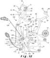
- the operation of the mechanism according to this embodiment is as follows: the starting STOP position is shown on the Figure 12 , in which the countdown chronograph mechanism and the striking mechanism are inactive.
- the various display organs for hours, tens of minutes, units of minutes and seconds are considered to have been positioned to display the predetermined time interval for the countdown. Only the second wheel 4 of the basic watch movement turns.
- the control member of the control device is pushed by a user to trigger the START so that the column wheel 14 rotates so as to open the clutch control clamp 8 and the clutch clamp 10 in order to engage the seconds wheel 4 and the chronograph drive wheel set 1.
- Opening the clutch control clamp 8 releases the striker lever 100, its third arm 102 no longer being retained by the clamp 8 previously resting on the pin 104.
- the striking lever 100 pivots about A in the counterclockwise direction, so that the first striking feeler lever 38, as well as the minute unit feeler lever 64, and the other tens of minutes and hours feeler levers, which were moved away from their respective cam to allow the display members for the countdown to be adjusted, pivot to move slightly closer to their respective cam.
- said striking lever 100 is kept away from the second cam 34 by the foot 64a of the minute unit feeler lever 64 resting on the beak 106 of the third arm 102 of the striking lever 100.
- the countdown is carried out in the same way as described above for the first embodiment, the chronograph drive wheel set 1, engaged with the second wheel 4, carrying the first second cam 34 and the strike stop cam 120 to rotate them counterclockwise.
- the display members for the hours, tens of minutes and units of minutes are also driven with their respective cams each time the second hand carried by the chronograph drive wheel set 1 passes through 0.
- the clockwise pivoting in H of the detection lever 90 and its arm 92 causes a counterclockwise pivoting in G of the minute units feeler lever 64 which gradually approaches the cam of the minute units 62 until it comes into contact with the latter when there are less than ten minutes left to count down.
- the hour and tens of minutes display members display 0, and the minute units display member does not yet display 0 so that the minute units feeler lever 64, in contact with the minute units cam 62, is not yet engaged in the notch 66 of said minute units cam 62.
- the striking feeler lever 38 is still not in contact with the second cam 34, the beak 106 of the third arm 102 of the striking lever 100 still being retained by the foot 64a of the minute units feeler lever 64.
- the striking lever 100 by its second arm 42, keeps the striking train stopped, the striking stop lever 44 being engaged in the stop star 32.
- rocking hook 122 is distant from the ringing stop cam 120.
- the minute units display member when there is less than one minute left to count down, the hour and tens of minutes display members still displaying 0, the minute units display member is positioned to display 0 so that the minute units feeler lever 64, being in contact with the minute units cam 62, engages in the notch 66 of said minute units cam 62 by pivoting in G in the counterclockwise direction.
- the foot 64a of the minute unit feeler lever 64 releases the third arm 102 and therefore the striking lever 100 so that said striking lever 100, under the action of its spring 101, pivots at A in the counterclockwise direction, the beak 38a of the striking lever 38 then coming into contact with the maximum radius of the second cam 34 carried by the chronograph drive wheel set 1.
- the strike stop lever 44 is arranged to start to disengage from the stop star 32 by pivoting clockwise around its pivot D.
- the countdown continues via the chronograph drive wheel 1 so that the seconds display member continues to rotate counterclockwise with the seconds cam 34.
- the striking feeler lever 38 pivots again at A in the counterclockwise direction.
- the pivoting at A of the striking feeler lever 38 signifies the pivoting at A in the counterclockwise direction of the striking lever 100 and in particular of its second arm 42 so that the striking stop lever 44 disengages from the stop star 32 by pivoting clockwise around its pivot D, and releases it.
- the chiming gear released the chime begins to ring at the set time before the end of the countdown.
- the fourth arm 108 of the striking lever 100 has also pivoted counterclockwise so that it causes the tilting of the tilting hook 122, via its pin 126, in the clockwise direction around its pivot F so that its arm 124 enters the radius of gyration of the beak 120a of the striking stop cam 120 carried by the chronograph drive wheel set 1.
- the seconds display member when the countdown ends and reaches practically zero, for example 5 seconds before the end of the countdown, the seconds display member is positioned with the second cam 34 and the strike stop cam 120 to display for example 5, the strike still being in progress.
- the positioning of the beak 120a of the stop cam 120 is such that said beak 120a comes into contact with the arm 124 of the rocking hook 122 to be able to drive it in rotation in F in the clockwise direction.
- the beak 38a of the ring feeler lever 38 has reached the end of the notch 36.
- the rocker hook 122 and the beak 120a of the strike stop cam 120 are configured so that, when the 0 is displayed at the end of the countdown, the rocker hook 122 controlled by the strike stop cam 120 has tilted to F in the clockwise direction sufficiently for its arm 128 to release the beak 112 of the strike stop rocker 110.
- the end-of-ring lever 110 is then released and pivots at E in the counterclockwise direction, under the action of its spring 118.
- the pivoting of the end-of-strike lever 110 at the end of the countdown means the counterclockwise pivoting of its first arm 111, so that the pin 113 carried by said arm 111 drives the hook-shaped end 114 of the fourth arm 108 of the strike lever 100 to pivot said strike lever 100 at A in the clockwise direction.
- This pivoting of the striking lever 100 at A in the clockwise direction allows the striking feeler lever 38 to be released from the second cam 34.
- the striking stop lever 44 is driven by the arm 42 to pivot in the counterclockwise direction around its pivot D to come to cooperate again with the stop star 32 and stop the striking train.
- the striking is stopped at the same time as the end of the countdown.
- the seconds display organ that is to say the chronograph second hand, continues its course with the second cam 34 and the strike stop cam 120 in the counterclockwise direction so that the beak 120a of said strike stop cam 120 passes the arm 124 of the rocker hook 122 and releases it.
- the rocker hook 122 pivots in F in the counterclockwise direction, under the action of its spring 130, until its second hook-shaped arm 128 comes to bear on the arm 111 of the end-of-strike lever 110.
- the rocker hook 122 leaves the radius of gyration of the strike stop cam 120, which makes it possible to avoid any unnecessary consumption of energy when the second hand continues its course while waiting for a manual stop of the chronograph mechanism.
- the present invention makes it possible to have a countdown chronograph mechanism provided with a striking mechanism which is triggered before the end of the countdown from a predetermined time interval to a predefined duration before the end of the countdown, in order to warn a user that the current countdown of said predetermined time interval is about to end.
- the present invention makes it possible to have a countdown timer having a pre-alarm using a mechanical striking mechanism, the end of the striking mechanism being synchronized with the end of the countdown of said predetermined time interval.
- the chronograph mechanism can stop at the end of the countdown of said predetermined time interval or remain activated so that the chronograph second hand continues to run without triggering a chime.
Landscapes
- Physics & Mathematics (AREA)
- General Physics & Mathematics (AREA)
- Acoustics & Sound (AREA)
- Measurement Of Unknown Time Intervals (AREA)
Claims (13)
- Mechanisches Uhrwerk, umfassend einen Chronographenmechanismus, der ausgelegt ist, um mindestens einen Countdown eines vorbestimmten Zeitintervalls auszuführen, umfassend Anzeigemittel, die ausgelegt sind, um mindestens die bis zum Ende des Countdowns des besagten vorbestimmten Zeitintervalls verbleibende Zeit anzuzeigen, mindestens ein Steuerungsorgan (11) des Starts des Countdowns, und einen Schlagwerkmechanismus, wobei der besagte Schlagwerkmechanismus ausgelegt ist, um vor dem Ende des Countdowns für einen bestimmten Zeitraum zu schlagen zu beginnen und um mit dem Ende des besagten Countdowns des besagten vorbestimmten Zeitintervalls zu schlagen aufzuhören, dadurch gekennzeichnet, dass der Chronographenmechanismus konfiguriert ist, um durch eine laterale oder vertikale Kupplungsvorrichtung (6) mit einem Basisuhrwerk kinematisch verbunden zu werden.
- Uhrwerk nach Anspruch 1, dadurch gekennzeichnet, dass der Chronographenmechanismus mindestens ein Chronographen-Mitnehmerdrehteil (1) umfasst, das ausgelegt ist, um einen Countdown auszuführen, und dadurch, dass der Schlagwerkmechanismus mindestens eine erste Kurvenscheibe (34) umfasst, die mit dem besagten Chronographen-Mitnehmerdrehteil (1) kinematisch verbunden ist und auf welcher der besagte bestimmte Zeitraum vor dem Ende des Countdowns des vorbestimmten Zeitintervalls programmiert ist, wobei die besagte erste Kurvenscheibe (34) ausgelegt ist, um eine Drehung über einen Zeitraum zu vollziehen, der länger als der bestimmte Zeitraum vor dem Ende des Countdowns des besagten vorbestimmten Zeitintervalls ist, ein Schlagwerk, eine erste Schlagwerkwippe (41; 100) umfassend einen ersten Schlagwerk-Tasthebel (38), ausgelegt, um mit der besagten ersten Kurvenscheibe (34) und dem besagten Schlagwerk zusammenzuwirken, um das Schlagwerk zu Beginn des bestimmten Zeitraums vor dem Ende des Countdowns des besagten vorbestimmten Zeitintervalls auszulösen, und einen Mechanismus zur Schlagwerkabstellung, ausgelegt, um mit der besagten ersten Schlagwerkwippe (41; 100) zusammenzuwirken, um das Anhalten des Schlagwerks am Ende des besagten bestimmten Zeitraums zeitgleich mit dem Ende des Countdowns des besagten vorbestimmten Zeitintervalls zu steuern.
- Uhrwerk nach dem vorstehenden Anspruch, dadurch gekennzeichnet, dass die Anzeigemittel des Chronographenmechanismus ein erstes Anzeigeorgan umfassen, das mit der ersten Kurvenscheibe (34) verbunden ist, um einen mithilfe des Chronographen-Mitnehmerdrehteils (1) erreichten Countdown anzuzeigen.
- Uhrwerk nach einem der Ansprüche 2 und 3, dadurch gekennzeichnet, dass das erste Anzeigeorgan ausgelegt ist, um einen Countdown der Minuteneinheiten anzuzeigen.
- Uhrwerk nach einem der Ansprüche 2 und 3, dadurch gekennzeichnet, dass das erste Anzeigeorgan ausgelegt ist, um einen Countdown der Sekunden anzuzeigen.
- Uhrwerk nach Anspruch 5, dadurch gekennzeichnet, dass die Anzeigemittel des Chronographenmechanismus ein zweites Anzeigeorgan der Minuteneinheiten (16) umfassen, das ausgelegt ist, um den Countdown der Minuteneinheiten des besagten vorbestimmten Zeitintervalls anzuzeigen, und dadurch, dass der Schlagwerkmechanismus eine zweite Kurvenscheibe der Minuteneinheiten (62) umfasst, die mit dem besagten zweiten Anzeigeorgan der Minuteneinheiten (16) verbunden ist, und einen dritten Tasthebel der Minuteneinheiten (64), der ausgelegt ist, um mit der besagten zweiten Kurvenscheibe der Minuteneinheiten (62) zusammenzuwirken, wobei die besagte zweite Kurvenscheibe der Minuteneinheiten (62) programmiert ist, um mit dem dritten Tasthebel der Minuteneinheiten (64) das Ende des Countdowns der Minuteneinheiten anzugeben, wobei der besagte dritte Tasthebel der Minuteneinheiten (64) ausgelegt ist, um mit dem ersten Schlagwerk-Tasthebel (38) so zusammenzuwirken, dass der besagte erste Schlagwerk-Tasthebel (38) mit der ersten Kurvenscheibe (34) am Ende des Countdowns der Minuteneinheiten zusammenwirkt.
- Uhrwerk nach Anspruch 6, dadurch gekennzeichnet, dass die Anzeigemittel des Chronographenmechanismus ein drittes Anzeigeorgan der Zehnerminuten (18) umfassen, das ausgelegt ist, um den Countdown der Zehnerminuten des besagten vorbestimmten Zeitintervalls anzuzeigen, und dadurch, dass der Schlagwerkmechanismus eine dritte Kurvenscheibe der Zehnerminuten (72) umfasst, die mit dem besagten dritten Anzeigeorgan der Zehnerminuten (18) verbunden ist, und einen vierten Tasthebel der Zehnerminuten (74), der ausgelegt ist, um mit der besagten dritten Kurvenscheibe der Zehnerminuten (72) zusammenzuwirken, wobei die besagte dritte Kurvenscheibe der Zehnerminuten (72) programmiert ist, um mit dem vierten Tasthebel der Zehnerminuten (74) das Ende des Countdowns der Zehnerminuten anzugeben, wobei der besagte vierte Tasthebel der Zehnerminuten (74) ausgelegt ist, um mit dem dritten Tasthebel der Minuteneinheiten (64) so zusammenzuwirken, dass der besagte dritte Tasthebel der Minuteneinheiten (64) mit der besagten zweiten Kurvenscheibe der Minuteneinheiten (62) am Ende des Countdowns der Zehnerminuten zusammenwirkt.
- Uhrwerk nach Anspruch 4, dadurch gekennzeichnet, dass die Anzeigemittel des Chronographenmechanismus ein drittes Anzeigeorgan der Zehnerminuten umfassen, das ausgelegt ist, um den Countdown der Zehnerminuten des besagten vorbestimmten Zeitintervalls anzuzeigen, und dadurch, dass der Schlagwerkmechanismus eine dritte Kurvenscheibe der Zehnerminuten (72) umfasst, die mit dem besagten dritten Anzeigeorgan der Zehnerminuten verbunden ist, und einen vierten Tasthebel der Zehnerminuten (74), der ausgelegt ist, um mit der besagten dritten Kurvenscheibe der Zehnerminuten (72) zusammenzuwirken, wobei die besagte dritte Kurvenscheibe der Zehnerminuten (72) programmiert ist, um mit dem vierten Tasthebel der Zehnerminuten (74) das Ende des Countdowns der Zehnerminuten anzugeben, wobei der besagte vierte Tasthebel der Zehnerminuten (74) ausgelegt ist, um mit dem ersten Schlagwerk-Tasthebel (38) so zusammenzuwirken, dass der besagte erste Schlagwerk-Tasthebel (38) mit der besagten ersten Kurvenscheibe (34) am Ende des Countdowns der Zehnerminuten zusammenwirkt.
- Uhrwerk nach einem der Ansprüche 7 und 8, dadurch gekennzeichnet, dass die Anzeigemittel des Chronographenmechanismus ein viertes Anzeigeorgan der Stunden (20) umfassen, das ausgelegt ist, um den Countdown der Stunden des besagten vorbestimmten Zeitintervalls anzuzeigen, und dadurch, dass der Schlagwerkmechanismus eine vierte Kurvenscheibe der Stunden (78) umfasst, die mit dem besagten vierten Anzeigeorgan der Stunden (20) verbunden ist, und einen fünften Tasthebel der Stunden (80), der ausgelegt ist, um mit der besagten vierten Kurvenscheibe der Stunden (78) zusammenzuwirken, wobei die besagte vierte Kurvenscheibe der Stunden (78) programmiert ist, um mit dem fünften Tasthebel der Stunden (80) das Ende des Countdowns der Stunden anzugeben, wobei der besagte fünfte Tasthebel der Stunden (80) ausgelegt ist, um mit dem vierten Tasthebel der Zehnerminuten (74) so zusammenzuwirken, dass der besagte vierte Tasthebel der Zehnerminuten (74) mit der besagten dritten Kurvenscheibe der Zehnerminuten (72) am Ende des Countdowns der Stunden zusammenwirkt.
- Uhrwerk nach Anspruch 9, dadurch gekennzeichnet, dass der dritte Tasthebel der Minuteneinheiten (64), der vierte Tasthebel der Zehnerminuten (74) und der fünfte Tasthebel der Stunden (80) eine einzige Wippe bilden.
- Uhrwerk nach Anspruch 10, dadurch gekennzeichnet, dass der erste Schlagwerk-Tasthebel (38), der dritte Tasthebel der Minuteneinheiten (64), der vierte Tasthebel der Zehnerminuten (74) und der fünfte Tasthebel der Stunden (80) eine einzige Wippe bilden.
- Uhrwerk nach einem der Ansprüche 2 bis 11, dadurch gekennzeichnet, dass der Mechanismus zur Schlagwerkabstellung eine Schlagwerkabstellwippe (50) umfasst, die einen zweiten Tasthebel zur Schlagwerkabstellung (40) umfasst, der ausgelegt ist, um mit der ersten Kurvenscheibe (34) zusammenzuwirken, um eine Auskupplung der Kupplungsvorrichtung (6) und das Anhalten des Schlagwerks am Ende des Countdowns des besagten vorbestimmten Zeitintervalls zu steuern.
- Uhrwerk nach einem der Ansprüche 2 bis 11, dadurch gekennzeichnet, dass der Mechanismus zur Schlagwerkabstellung eine Schlagwerkabstellwippe (110) umfasst, die ausgelegt ist, um mit der ersten Schlagwerkwippe (100) zusammenzuwirken, und eine Kurvenscheibe zum Anhalten des Schlagwerks (120), die mit dem Chronographen-Mitnehmerdrehteil (1) kinematisch verbunden ist und ausgelegt ist, um die besagte Schlagwerkabstellwippe (110) zu steuern, um das Schlagwerk am Ende des Countdowns des besagten vorbestimmten Zeitintervalls anzuhalten, ohne die Kupplungsvorrichtung (6) auszukuppeln.
Applications Claiming Priority (2)
| Application Number | Priority Date | Filing Date | Title |
|---|---|---|---|
| EP20172014 | 2020-04-29 | ||
| PCT/EP2021/060999 WO2021219646A1 (fr) | 2020-04-29 | 2021-04-27 | Mouvement horloger comprenant un mécanisme de chronographe compte à rebours et un mécanisme de sonnerie |
Publications (2)
| Publication Number | Publication Date |
|---|---|
| EP4143640A1 EP4143640A1 (de) | 2023-03-08 |
| EP4143640B1 true EP4143640B1 (de) | 2025-04-30 |
Family
ID=70476126
Family Applications (1)
| Application Number | Title | Priority Date | Filing Date |
|---|---|---|---|
| EP21721113.5A Active EP4143640B1 (de) | 2020-04-29 | 2021-04-27 | Uhrwerk, das einen chronographenmechanismus mit countdown-funktion und einen schlagwerkmechanismus umfasst |
Country Status (6)
| Country | Link |
|---|---|
| US (1) | US12510866B2 (de) |
| EP (1) | EP4143640B1 (de) |
| JP (1) | JP7692435B2 (de) |
| CN (1) | CN115803688B (de) |
| CH (1) | CH717358A2 (de) |
| WO (1) | WO2021219646A1 (de) |
Families Citing this family (2)
| Publication number | Priority date | Publication date | Assignee | Title |
|---|---|---|---|---|
| EP4202577A1 (de) * | 2021-12-21 | 2023-06-28 | Manufacture d'Horlogerie Audemars Piguet SA | Wippevorrichtung eines uhrwerks |
| CH719555B1 (fr) * | 2022-03-28 | 2024-10-31 | Richemont Int Sa | Mécanisme de chronographe avec sonnerie |
Family Cites Families (17)
| Publication number | Priority date | Publication date | Assignee | Title |
|---|---|---|---|---|
| US989807A (en) * | 1909-06-30 | 1911-04-18 | Guy W Robins | Time-indicator. |
| US1153466A (en) * | 1915-02-11 | 1915-09-14 | Albert Tuerk | Culinary timing apparatus. |
| FR1154660A (fr) * | 1955-12-26 | 1958-04-15 | Compteur de temps pour communications téléphoniques | |
| JPS5651247Y2 (de) * | 1979-12-19 | 1981-11-30 | ||
| JP3266917B2 (ja) * | 1991-08-29 | 2002-03-18 | セイコーエプソン株式会社 | 多機能電子時計 |
| WO2002077724A2 (fr) * | 2001-03-21 | 2002-10-03 | Glashütter Uhrenbetrieb GmbH | Piece d'horlogerie comportant un dispositif de sonnerie |
| WO2002077721A1 (fr) * | 2001-03-21 | 2002-10-03 | Glashütter Uhrenbetrieb GmbH | Dispositif de reglage d'un indicateur horaire |
| DE60111273T2 (de) * | 2001-03-21 | 2006-03-23 | Glashütter Uhrenbetrieb GmbH | Auslösemechanismus eines Schlagwerks für eine Uhr mit Kurzzeitmesser |
| CN100385352C (zh) | 2001-03-21 | 2008-04-30 | 格拉舒特钟表厂有限责任公司 | 具有两个旋转方向的计时器 |
| US7597471B2 (en) * | 2005-11-24 | 2009-10-06 | Vaucher Manufacture Fleurier S.A. | Time piece chronograph clockwork movement |
| EP1916574A1 (de) * | 2006-10-20 | 2008-04-30 | Vaucher Manufacture Fleurier SA | Zeiger für Uhren, Uhrwerk zum Antreiben eines solchen Zeigers und entsprechende Uhr |
| CH703361A2 (fr) * | 2010-06-22 | 2011-12-30 | Artisans Horlogers Sarl | Mouvement horloger presentant des fonctions de chronographe et de compte-a-rebours. |
| CH704732A2 (fr) * | 2011-03-22 | 2012-09-28 | Imh Sa Innovation Manufactures Horlogeres Sa | Chronographe compte à rebours à sonnerie. |
| EP3026506B1 (de) * | 2014-11-26 | 2019-01-16 | The Swatch Group Management Services AG | Zeitmessgerät mit Geschwindigkeitswahlschalter |
| EP3159753B1 (de) * | 2015-10-21 | 2018-10-10 | Blancpain SA. | Zeitgeber für einstellbare weckwiederholung für mechanische armbanduhr |
| WO2019243940A1 (fr) * | 2018-06-20 | 2019-12-26 | Patek Philippe Sa Geneve | Mecanisme de reveil et piece d'horlogerie comportant un tel mecanisme |
| EP3904967B1 (de) | 2020-04-29 | 2022-09-28 | Patek Philippe SA Genève | Steuervorrichtung eines uhrwerkmechanismus |
-
2021
- 2021-04-27 CH CH00452/21A patent/CH717358A2/fr unknown
- 2021-04-27 JP JP2022566091A patent/JP7692435B2/ja active Active
- 2021-04-27 EP EP21721113.5A patent/EP4143640B1/de active Active
- 2021-04-27 WO PCT/EP2021/060999 patent/WO2021219646A1/fr not_active Ceased
- 2021-04-27 CN CN202180046314.3A patent/CN115803688B/zh active Active
- 2021-04-27 US US17/922,191 patent/US12510866B2/en active Active
Also Published As
| Publication number | Publication date |
|---|---|
| CN115803688B (zh) | 2025-02-25 |
| WO2021219646A1 (fr) | 2021-11-04 |
| EP4143640A1 (de) | 2023-03-08 |
| US20230161297A1 (en) | 2023-05-25 |
| JP2023523466A (ja) | 2023-06-05 |
| JP7692435B2 (ja) | 2025-06-13 |
| US12510866B2 (en) | 2025-12-30 |
| CN115803688A (zh) | 2023-03-14 |
| CH717358A2 (fr) | 2021-10-29 |
Similar Documents
| Publication | Publication Date | Title |
|---|---|---|
| EP1777598B1 (de) | Uhr mit einem Mechanismus zur Messung von einstellbaren vorbestimmten Zeitdauern | |
| EP2453322B1 (de) | Schneller Korrektor einer Zeitgrößenanzeige für Uhr | |
| EP2498143B1 (de) | Isolationsmechanismus zwischen Uhrmechanismen zur Auslösung verschiedener Schlagwerkssignale | |
| EP2498148B1 (de) | Sicherheitsmechanismus gegen fehlerhaften Bedienungen der Steuerungen eines Minuten-repetierwerks | |
| EP2498147B1 (de) | Schlagwerksblock und Antriebsmechanismus für Weckerwerk für Uhren mit Schlagwerken | |
| EP2498146B1 (de) | Weckerwerkmechanismus mit Hilfe des großen Schlagwerks | |
| EP2498149B1 (de) | Zeitbegrenzungsmechanismus für Uhrmechanismus | |
| EP4143640B1 (de) | Uhrwerk, das einen chronographenmechanismus mit countdown-funktion und einen schlagwerkmechanismus umfasst | |
| EP4320487B1 (de) | Uhr mit repetition und alarm | |
| EP3811158B1 (de) | Weckmechanismus und mit einem solchen mechanismus ausgestattete uhr | |
| EP3904967A1 (de) | Steuervorrichtung eines uhrwerkmechanismus | |
| CH704590A2 (fr) | Mécanisme d'isolement entre mécanismes horlogers de déclenchement de différents signaux sonores. | |
| EP1760548B1 (de) | Uhr mit einer Vorrichtung zur Zeitangabe durch Läutwerk | |
| EP4071562B1 (de) | Schlagwerkmechanismus und diesen umfassende uhr | |
| EP4071561B1 (de) | Repetitionsuhr | |
| EP3800512B1 (de) | On-demand-anzeigevorrichtung für uhr | |
| EP3811159B1 (de) | Wecken mechanismus und zeitstück mit einem solchen mechanismus | |
| EP4254076A1 (de) | Zählvorrichtung einer uhr | |
| CH704624A2 (fr) | Mobile de délai et mécanisme limiteur de durée pour mécanisme horloger. | |
| EP1760550A1 (de) | Uhr mit grossem Schlagwerk | |
| EP1760544A1 (de) | Vorrichtung zur Anzeige von Federspannung | |
| CH719555B1 (fr) | Mécanisme de chronographe avec sonnerie | |
| CH700605A1 (fr) | Mouvement de montre a fonction alarme. | |
| EP1760553A1 (de) | Uhr mit grossem Schlagwerk | |
| EP1760552A1 (de) | Uhr mit grossem Schlagwerk |
Legal Events
| Date | Code | Title | Description |
|---|---|---|---|
| STAA | Information on the status of an ep patent application or granted ep patent |
Free format text: STATUS: UNKNOWN |
|
| STAA | Information on the status of an ep patent application or granted ep patent |
Free format text: STATUS: THE INTERNATIONAL PUBLICATION HAS BEEN MADE |
|
| PUAI | Public reference made under article 153(3) epc to a published international application that has entered the european phase |
Free format text: ORIGINAL CODE: 0009012 |
|
| STAA | Information on the status of an ep patent application or granted ep patent |
Free format text: STATUS: REQUEST FOR EXAMINATION WAS MADE |
|
| 17P | Request for examination filed |
Effective date: 20221108 |
|
| AK | Designated contracting states |
Kind code of ref document: A1 Designated state(s): AL AT BE BG CH CY CZ DE DK EE ES FI FR GB GR HR HU IE IS IT LI LT LU LV MC MK MT NL NO PL PT RO RS SE SI SK SM TR |
|
| P01 | Opt-out of the competence of the unified patent court (upc) registered |
Effective date: 20230521 |
|
| DAV | Request for validation of the european patent (deleted) | ||
| DAX | Request for extension of the european patent (deleted) | ||
| GRAP | Despatch of communication of intention to grant a patent |
Free format text: ORIGINAL CODE: EPIDOSNIGR1 |
|
| STAA | Information on the status of an ep patent application or granted ep patent |
Free format text: STATUS: GRANT OF PATENT IS INTENDED |
|
| INTG | Intention to grant announced |
Effective date: 20241206 |
|
| GRAS | Grant fee paid |
Free format text: ORIGINAL CODE: EPIDOSNIGR3 |
|
| GRAA | (expected) grant |
Free format text: ORIGINAL CODE: 0009210 |
|
| STAA | Information on the status of an ep patent application or granted ep patent |
Free format text: STATUS: THE PATENT HAS BEEN GRANTED |
|
| AK | Designated contracting states |
Kind code of ref document: B1 Designated state(s): AL AT BE BG CH CY CZ DE DK EE ES FI FR GB GR HR HU IE IS IT LI LT LU LV MC MK MT NL NO PL PT RO RS SE SI SK SM TR |
|
| REG | Reference to a national code |
Ref country code: CH Ref legal event code: EP Ref country code: GB Ref legal event code: FG4D Free format text: NOT ENGLISH |
|
| REG | Reference to a national code |
Ref country code: IE Ref legal event code: FG4D Free format text: LANGUAGE OF EP DOCUMENT: FRENCH |
|
| REG | Reference to a national code |
Ref country code: DE Ref legal event code: R096 Ref document number: 602021029995 Country of ref document: DE |
|
| REG | Reference to a national code |
Ref country code: NL Ref legal event code: MP Effective date: 20250430 |
|
| REG | Reference to a national code |
Ref country code: AT Ref legal event code: MK05 Ref document number: 1790586 Country of ref document: AT Kind code of ref document: T Effective date: 20250430 |
|
| PG25 | Lapsed in a contracting state [announced via postgrant information from national office to epo] |
Ref country code: FI Free format text: LAPSE BECAUSE OF FAILURE TO SUBMIT A TRANSLATION OF THE DESCRIPTION OR TO PAY THE FEE WITHIN THE PRESCRIBED TIME-LIMIT Effective date: 20250430 Ref country code: ES Free format text: LAPSE BECAUSE OF FAILURE TO SUBMIT A TRANSLATION OF THE DESCRIPTION OR TO PAY THE FEE WITHIN THE PRESCRIBED TIME-LIMIT Effective date: 20250430 Ref country code: PT Free format text: LAPSE BECAUSE OF FAILURE TO SUBMIT A TRANSLATION OF THE DESCRIPTION OR TO PAY THE FEE WITHIN THE PRESCRIBED TIME-LIMIT Effective date: 20250901 |
|
| REG | Reference to a national code |
Ref country code: LT Ref legal event code: MG9D |
|
| PG25 | Lapsed in a contracting state [announced via postgrant information from national office to epo] |
Ref country code: GR Free format text: LAPSE BECAUSE OF FAILURE TO SUBMIT A TRANSLATION OF THE DESCRIPTION OR TO PAY THE FEE WITHIN THE PRESCRIBED TIME-LIMIT Effective date: 20250731 Ref country code: NO Free format text: LAPSE BECAUSE OF FAILURE TO SUBMIT A TRANSLATION OF THE DESCRIPTION OR TO PAY THE FEE WITHIN THE PRESCRIBED TIME-LIMIT Effective date: 20250730 |
|
| PG25 | Lapsed in a contracting state [announced via postgrant information from national office to epo] |
Ref country code: NL Free format text: LAPSE BECAUSE OF FAILURE TO SUBMIT A TRANSLATION OF THE DESCRIPTION OR TO PAY THE FEE WITHIN THE PRESCRIBED TIME-LIMIT Effective date: 20250430 Ref country code: PL Free format text: LAPSE BECAUSE OF FAILURE TO SUBMIT A TRANSLATION OF THE DESCRIPTION OR TO PAY THE FEE WITHIN THE PRESCRIBED TIME-LIMIT Effective date: 20250430 |
|
| PG25 | Lapsed in a contracting state [announced via postgrant information from national office to epo] |
Ref country code: BG Free format text: LAPSE BECAUSE OF FAILURE TO SUBMIT A TRANSLATION OF THE DESCRIPTION OR TO PAY THE FEE WITHIN THE PRESCRIBED TIME-LIMIT Effective date: 20250430 |
|
| PG25 | Lapsed in a contracting state [announced via postgrant information from national office to epo] |
Ref country code: HR Free format text: LAPSE BECAUSE OF FAILURE TO SUBMIT A TRANSLATION OF THE DESCRIPTION OR TO PAY THE FEE WITHIN THE PRESCRIBED TIME-LIMIT Effective date: 20250430 |
|
| PG25 | Lapsed in a contracting state [announced via postgrant information from national office to epo] |
Ref country code: AT Free format text: LAPSE BECAUSE OF FAILURE TO SUBMIT A TRANSLATION OF THE DESCRIPTION OR TO PAY THE FEE WITHIN THE PRESCRIBED TIME-LIMIT Effective date: 20250430 |
|
| PG25 | Lapsed in a contracting state [announced via postgrant information from national office to epo] |
Ref country code: RS Free format text: LAPSE BECAUSE OF FAILURE TO SUBMIT A TRANSLATION OF THE DESCRIPTION OR TO PAY THE FEE WITHIN THE PRESCRIBED TIME-LIMIT Effective date: 20250731 |
|
| PG25 | Lapsed in a contracting state [announced via postgrant information from national office to epo] |
Ref country code: IS Free format text: LAPSE BECAUSE OF FAILURE TO SUBMIT A TRANSLATION OF THE DESCRIPTION OR TO PAY THE FEE WITHIN THE PRESCRIBED TIME-LIMIT Effective date: 20250830 |
|
| PG25 | Lapsed in a contracting state [announced via postgrant information from national office to epo] |
Ref country code: LV Free format text: LAPSE BECAUSE OF FAILURE TO SUBMIT A TRANSLATION OF THE DESCRIPTION OR TO PAY THE FEE WITHIN THE PRESCRIBED TIME-LIMIT Effective date: 20250430 |
|
| PG25 | Lapsed in a contracting state [announced via postgrant information from national office to epo] |
Ref country code: SM Free format text: LAPSE BECAUSE OF FAILURE TO SUBMIT A TRANSLATION OF THE DESCRIPTION OR TO PAY THE FEE WITHIN THE PRESCRIBED TIME-LIMIT Effective date: 20250430 Ref country code: DK Free format text: LAPSE BECAUSE OF FAILURE TO SUBMIT A TRANSLATION OF THE DESCRIPTION OR TO PAY THE FEE WITHIN THE PRESCRIBED TIME-LIMIT Effective date: 20250430 |
|
| PG25 | Lapsed in a contracting state [announced via postgrant information from national office to epo] |
Ref country code: CZ Free format text: LAPSE BECAUSE OF FAILURE TO SUBMIT A TRANSLATION OF THE DESCRIPTION OR TO PAY THE FEE WITHIN THE PRESCRIBED TIME-LIMIT Effective date: 20250430 |
|
| PG25 | Lapsed in a contracting state [announced via postgrant information from national office to epo] |
Ref country code: EE Free format text: LAPSE BECAUSE OF FAILURE TO SUBMIT A TRANSLATION OF THE DESCRIPTION OR TO PAY THE FEE WITHIN THE PRESCRIBED TIME-LIMIT Effective date: 20250430 |
|
| PG25 | Lapsed in a contracting state [announced via postgrant information from national office to epo] |
Ref country code: SK Free format text: LAPSE BECAUSE OF FAILURE TO SUBMIT A TRANSLATION OF THE DESCRIPTION OR TO PAY THE FEE WITHIN THE PRESCRIBED TIME-LIMIT Effective date: 20250430 |
|
| PG25 | Lapsed in a contracting state [announced via postgrant information from national office to epo] |
Ref country code: IT Free format text: LAPSE BECAUSE OF FAILURE TO SUBMIT A TRANSLATION OF THE DESCRIPTION OR TO PAY THE FEE WITHIN THE PRESCRIBED TIME-LIMIT Effective date: 20250430 |