EP4143451B1 - A control system for controlling a magnetic suspension system - Google Patents
A control system for controlling a magnetic suspension system Download PDFInfo
- Publication number
- EP4143451B1 EP4143451B1 EP21720797.6A EP21720797A EP4143451B1 EP 4143451 B1 EP4143451 B1 EP 4143451B1 EP 21720797 A EP21720797 A EP 21720797A EP 4143451 B1 EP4143451 B1 EP 4143451B1
- Authority
- EP
- European Patent Office
- Prior art keywords
- controllers
- magnetic
- control system
- control
- magnetic actuators
- Prior art date
- Legal status (The legal status is an assumption and is not a legal conclusion. Google has not performed a legal analysis and makes no representation as to the accuracy of the status listed.)
- Active
Links
Images


Classifications
-
- H—ELECTRICITY
- H01—ELECTRIC ELEMENTS
- H01F—MAGNETS; INDUCTANCES; TRANSFORMERS; SELECTION OF MATERIALS FOR THEIR MAGNETIC PROPERTIES
- H01F7/00—Magnets
- H01F7/06—Electromagnets; Actuators including electromagnets
- H01F7/20—Electromagnets; Actuators including electromagnets without armatures
- H01F7/206—Electromagnets for lifting, handling or transporting of magnetic pieces or material
-
- F—MECHANICAL ENGINEERING; LIGHTING; HEATING; WEAPONS; BLASTING
- F16—ENGINEERING ELEMENTS AND UNITS; GENERAL MEASURES FOR PRODUCING AND MAINTAINING EFFECTIVE FUNCTIONING OF MACHINES OR INSTALLATIONS; THERMAL INSULATION IN GENERAL
- F16C—SHAFTS; FLEXIBLE SHAFTS; ELEMENTS OR CRANKSHAFT MECHANISMS; ROTARY BODIES OTHER THAN GEARING ELEMENTS; BEARINGS
- F16C32/00—Bearings not otherwise provided for
- F16C32/04—Bearings not otherwise provided for using magnetic or electric supporting means
- F16C32/0406—Magnetic bearings
- F16C32/044—Active magnetic bearings
- F16C32/0444—Details of devices to control the actuation of the electromagnets
- F16C32/0451—Details of controllers, i.e. the units determining the power to be supplied, e.g. comparing elements, feedback arrangements with P.I.D. control
-
- B—PERFORMING OPERATIONS; TRANSPORTING
- B60—VEHICLES IN GENERAL
- B60L—PROPULSION OF ELECTRICALLY-PROPELLED VEHICLES; SUPPLYING ELECTRIC POWER FOR AUXILIARY EQUIPMENT OF ELECTRICALLY-PROPELLED VEHICLES; ELECTRODYNAMIC BRAKE SYSTEMS FOR VEHICLES IN GENERAL; MAGNETIC SUSPENSION OR LEVITATION FOR VEHICLES; MONITORING OPERATING VARIABLES OF ELECTRICALLY-PROPELLED VEHICLES; ELECTRIC SAFETY DEVICES FOR ELECTRICALLY-PROPELLED VEHICLES
- B60L13/00—Electric propulsion for monorail vehicles, suspension vehicles or rack railways; Magnetic suspension or levitation for vehicles
- B60L13/04—Magnetic suspension or levitation for vehicles
-
- F—MECHANICAL ENGINEERING; LIGHTING; HEATING; WEAPONS; BLASTING
- F16—ENGINEERING ELEMENTS AND UNITS; GENERAL MEASURES FOR PRODUCING AND MAINTAINING EFFECTIVE FUNCTIONING OF MACHINES OR INSTALLATIONS; THERMAL INSULATION IN GENERAL
- F16C—SHAFTS; FLEXIBLE SHAFTS; ELEMENTS OR CRANKSHAFT MECHANISMS; ROTARY BODIES OTHER THAN GEARING ELEMENTS; BEARINGS
- F16C32/00—Bearings not otherwise provided for
- F16C32/04—Bearings not otherwise provided for using magnetic or electric supporting means
- F16C32/0406—Magnetic bearings
- F16C32/044—Active magnetic bearings
- F16C32/0444—Details of devices to control the actuation of the electromagnets
- F16C32/0457—Details of the power supply to the electromagnets
-
- F—MECHANICAL ENGINEERING; LIGHTING; HEATING; WEAPONS; BLASTING
- F16—ENGINEERING ELEMENTS AND UNITS; GENERAL MEASURES FOR PRODUCING AND MAINTAINING EFFECTIVE FUNCTIONING OF MACHINES OR INSTALLATIONS; THERMAL INSULATION IN GENERAL
- F16C—SHAFTS; FLEXIBLE SHAFTS; ELEMENTS OR CRANKSHAFT MECHANISMS; ROTARY BODIES OTHER THAN GEARING ELEMENTS; BEARINGS
- F16C32/00—Bearings not otherwise provided for
- F16C32/04—Bearings not otherwise provided for using magnetic or electric supporting means
- F16C32/0406—Magnetic bearings
- F16C32/044—Active magnetic bearings
- F16C32/0459—Details of the magnetic circuit
-
- H—ELECTRICITY
- H02—GENERATION; CONVERSION OR DISTRIBUTION OF ELECTRIC POWER
- H02K—DYNAMO-ELECTRIC MACHINES
- H02K7/00—Arrangements for handling mechanical energy structurally associated with dynamo-electric machines, e.g. structural association with mechanical driving motors or auxiliary dynamo-electric machines
- H02K7/08—Structural association with bearings
- H02K7/09—Structural association with bearings with magnetic bearings
Definitions
- the disclosure relates to a control system for controlling a magnetic suspension system that can be, for example but not necessarily, an active magnetic bearing "AMB" system. Furthermore, the disclosure relates to a magnetic suspension system.
- AMB active magnetic bearing
- Magnetic suspension systems such as e.g. active magnetic bearing "AMB" systems are commonly used for levitating e.g. rotating or oscillating objects. Such a system is for example known from the document EP 1 912 312 A2 .
- a typical application is levitation of a rotor of an electrical machine, e.g. a high-speed electrical machine.
- the levitation is accomplished by balancing attractive forces of oppositely acting magnets and other forces acting on an object to be levitated, where at least one of the magnets is a controllable electromagnet.
- There are several different kinds of magnetic suspension systems Some systems use permanent magnet material to generate bias magnetic fluxes, while others use direct biasing currents to generate the bias magnetic fluxes. The biasing is used to linearize the operation of the system and to improve control dynamics of the system.
- Magnetic forces acting in degrees of freedom of a levitated object need to be controlled actively because of inherent instability of the magnetic levitation.
- the instability is caused by the fact that a magnetic attractive force acting between a magnet and an object made of e.g. ferromagnetic material increases when an airgap between the magnet and the object gets smaller.
- a magnetic attractive force acting between a magnet and an object made of e.g. ferromagnetic material increases when an airgap between the magnet and the object gets smaller.
- controller current sources are needed. All of them should be operated in a centralized manner to provide a good controllability of the AMB system and to take into account couplings between different degrees of freedom.
- AMB systems with longer shafts where additional bearings are necessary to provide reliable levitation.
- Each radial bearing requires four controller current sources, thus rapidly increasing the total amount of the controller current sources.
- a control system needs to have a high number of controller current sources to provide magnetic levitation.
- the challenge related to the high number of controller current sources has been solved either by modifying the power electronics to provide more controller current sources, which requires additional development and reduces cost efficiency.
- a decentralized approach has been utilized when different bearings are operated independently, in which case controllability and stability of magnetic levitation may be reduced.
- geometric when used as a prefix means a geometric concept that is not necessarily a part of any physical object.
- the geometric concept can be for example a geometric point, a straight or curved geometric line, a geometric plane, a non-planar geometric surface, a geometric space, or any other geometric entity that is zero, one, two, or three dimensional.
- a new control system for controlling a magnetic suspension system that can be, for example but not necessarily, an active magnetic bearing "AMB" system for levitating a rotating element such as e.g. a rotor of an electrical machine.
- AMB active magnetic bearing
- a control system comprises controllers each of which is configured to control one or more of magnetic actuators of a magnetic suspension system for magnetically levitating an object.
- One of the controllers is configured to operate as a master controller and other one or ones of the controllers are configured to operate as one or more slave controllers.
- the master controller is communicatively connected with one or more digital data transfer links to the one or more slave controllers, wherein digital data transferred via the one or more digital data transfer links is indicative of reference values of electric currents of coils of the magnetic actuators, the master controller being configured to control operation of the one or more slave controllers.
- Two or more of the controllers are connectable to a same coil of the magnetic actuators, and the master controller is configured to select one of the two or more controllers to supply electric current to the same coil, when the two or more of the controllers are connected to the same coil of the magnetic actuators.
- the control system according to the invention makes it possible to implement a centralized control with separate controllers and thereby without a need for a controller having a high number of controller current sources.
- Figure 1a shows a magnetic suspension system that comprises a control system 100 according to an exemplifying and non-limiting embodiment.
- the magnetic suspension system comprises magnetic actuators 108, 109, 110, 111, and 112 configured to magnetically levitate an object 113.
- the magnetic suspension system is an active magnetic bearing "AMB" system and the object 113 is a rotating element that can be e.g. a rotor of an electrical machine.
- the magnetic actuators 108, 109, 111, and 112 are radial magnetic bearings, and the magnetic actuator 110 is an axial magnetic bearing.
- the magnetic suspension system comprises a position sensor system 114 for generating position signals indicative of a position of the object 113 with respect to a reference position of the object.
- the position sensor system 114 may comprise for example inductive sensors where the inductance of each inductive sensor is dependent on a distance from the inductive sensor under consideration to a surface of the object 113. It is also possible that a position sensor system comprises means for forming the position signals based on differences between the inductances of the coils of the magnetic actuators 108-112. The inductance of each coil can be estimated based on e.g. the rate of change of electric current di/dt when the voltage directed to the coil under consideration is changed in a stepwise manner. In this exemplifying case, there is no need for separate position sensors.
- the control system 100 is configured to control electric currents of the coils of the magnetic actuators 108-112 based on the above-mentioned position signals.
- the control system 100 comprises controllers 101 and 102 each of which is configured to control corresponding ones of the magnetic actuators for magnetically levitating the object 113.
- One of the controllers 101 and 102 is configured to operate as a master controller and other one of the controllers is configured to operate as a slave controller.
- the master controller is communicatively connected with a digital data transfer link 104 to the slave controller, and the master controller is configured to control operation of the slave controller.
- the digital data transferred between the controllers 101 and 102 is indicative of reference values of the electric currents of the coils of the magnetic actuators, and the controllers 101 and 102 are configured to use the digital data to coordinate the operation of the controllers 101 and 102 so that for example situations where two or more of the magnetic actuators act against each other can be avoided.
- all computations related to the magnetic levitation are carried out by the master controller and the one or more slave controllers are used only as controllable current sources that are controlled by reference values received from the master controller via digital data transfer links.
- each of the controllers comprises a control board that is configured to carry out computations related to the magnetic levitation. Furthermore, each of the controllers comprises replaceable power boards each of which is configured to supply electric current in accordance with a control signal received from the control board.
- the control board is denoted with a reference 105 and the replaceable power boards are denoted with a reference 106.
- the control board 105 shown in figure 1b may comprise one or more processor circuits each of which can be a programmable processor circuit provided with appropriate software, a dedicated hardware processor such as for example an application specific integrated circuit "ASIC", or a configurable hardware processor such as for example a field programmable gate array "FPGA". Furthermore, the control board 105 may comprise one or more memory devices such as e.g. random-access memory "RAM” devices. Each of the replaceable power boards 106 may comprise e.g. transistors configured to constitute e.g. a full-H bridge or a half-H bridge and driver circuits for driving the transistors.
- FIG. 2 illustrates a part of a magnetic suspension system that comprises a control system 200 according to an exemplifying and non-limiting embodiment.
- the control system comprises controllers 201, 202, and 203 for controlling magnetic actuators, e.g. active magnetic bearings, of the magnetic suspension system.
- the controllers 202 and 203 are connected to a same coil 207 of the magnetic actuators. This arrangement provides redundancy and thereby improves reliability.
- One of the controllers 201, 202, and 203 acts as a master controller that is configured to select which one of the controllers 202 and 203 is used for supply electric current to the coil 207.
- the master controller is configured to compare one or more quantities related to operation of each of the controllers 202 and 203 to admissible ranges of the one or more quantities, and to select one of these controllers 202 and 203 based at least partly on the comparisons.
- the one or more quantities related to the operation of each controller may comprise for example measured electric currents, reference values of the electric currents, direct "DC" voltages of the controller, position estimates of a levitated object, and/or temperatures measured in the controller.
- three or more controllers are connected to a same coil and these controllers are configured to produce reference values for electric current of the coil, and a master controller is configured to select one of these controllers based on majority of the reference values so that the reference value produced by the selected one of the controllers belongs to the majority of the reference values.
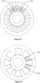
- Figures 3a, 3b , 3c, and 3d illustrate exemplifying winding arrangements of magnetic actuators that are controllable with control systems according to exemplifying and non-limiting embodiments.
- Figure 3a illustrates an exemplifying winding arrangement where each electromagnet pole-pair is supplied with one controller current source.
- Figure 3b illustrates an exemplifying winding arrangement where each electromagnet pole-pair is provided with two windings supplied with different controller current sources.
- the controller current sources belong advantageously to different controllers e.g. to improve redundancy.
- Figure 3b shows two exemplifying windings 331 and 332 arranged to magnetize a same electromagnet pole-pair.
- the winding 331 depicted with a solid line can be supplied with a first controller, and the winding 332 depicted with a dashed line can be supplied with a second controller.
- Figure 3c illustrates an exemplifying arrangement where there are more than one set of electromagnets for implementing a control in desired degrees of freedom, i.e. in mutually perpendicular directions in the figure plane of figure 3c.
- Figure 3c shows two exemplifying windings 333 and 334 arranged to magnetize electromagnets which belong to different ones of the above-mentioned sets.
- the winding 333 depicted with a solid line can be supplied with a first controller current source, and the winding 334 depicted with a dashed line can be supplied with a second controller current source.
- the first and second controller current sources belong advantageously to different controllers e.g. to improve redundancy.
- the possibility to supply electric currents from different controller current sources, which advantageously belong to different controllers, to parallel windings of a given electromagnet pole-pair or to windings of different electromagnets for controlling same degrees of freedom allows to increase the bandwidth of the control because inductances of the windings which are limiting the bandwidth are reduced when the number of controller current sources increases. This allows to operate systems of various sizes by increasing the number of controllers without changing power electronics.
- Figure 3d illustrates an exemplifying winding arrangement where each electromagnet pole has a separate winding that can be supplied with a separate controller current source.
- Figure 3d shows two exemplifying windings 335 and 336 arranged to magnetize poles of an electromagnet and supplied with different controller current sources.
Landscapes
- Engineering & Computer Science (AREA)
- General Engineering & Computer Science (AREA)
- Physics & Mathematics (AREA)
- Electromagnetism (AREA)
- Mechanical Engineering (AREA)
- Power Engineering (AREA)
- Transportation (AREA)
- Magnetic Bearings And Hydrostatic Bearings (AREA)
Description
- The disclosure relates to a control system for controlling a magnetic suspension system that can be, for example but not necessarily, an active magnetic bearing "AMB" system. Furthermore, the disclosure relates to a magnetic suspension system.
- Magnetic suspension systems such as e.g. active magnetic bearing "AMB" systems are commonly used for levitating e.g. rotating or oscillating objects. Such a system is for example known from the document
EP 1 912 312 A2 . A typical application is levitation of a rotor of an electrical machine, e.g. a high-speed electrical machine. In many cases, the levitation is accomplished by balancing attractive forces of oppositely acting magnets and other forces acting on an object to be levitated, where at least one of the magnets is a controllable electromagnet. In principle, it is also possible to balance an attractive force of one controllable electromagnet with other forces, e.g. the gravity force, acting against the attractive force of the electromagnet. There are several different kinds of magnetic suspension systems. Some systems use permanent magnet material to generate bias magnetic fluxes, while others use direct biasing currents to generate the bias magnetic fluxes. The biasing is used to linearize the operation of the system and to improve control dynamics of the system. - Magnetic forces acting in degrees of freedom of a levitated object, e.g. a rotor of an electrical machine, need to be controlled actively because of inherent instability of the magnetic levitation. The instability is caused by the fact that a magnetic attractive force acting between a magnet and an object made of e.g. ferromagnetic material increases when an airgap between the magnet and the object gets smaller. In a typical active magnetic bearing system, there are five degrees of freedom to be controlled and thus ten controller current sources are needed. All of them should be operated in a centralized manner to provide a good controllability of the AMB system and to take into account couplings between different degrees of freedom.
- There are AMB systems with longer shafts where additional bearings are necessary to provide reliable levitation. Each radial bearing requires four controller current sources, thus rapidly increasing the total amount of the controller current sources. Thus, in an AMB system of the kind mentioned above, a control system needs to have a high number of controller current sources to provide magnetic levitation. The challenge related to the high number of controller current sources has been solved either by modifying the power electronics to provide more controller current sources, which requires additional development and reduces cost efficiency. Alternatively, a decentralized approach has been utilized when different bearings are operated independently, in which case controllability and stability of magnetic levitation may be reduced.
- The following presents a simplified summary in order to provide a basic understanding of some aspects of various invention embodiments. The summary is not an extensive overview of the invention. It is neither intended to identify key or critical elements of the invention nor to delineate the scope of the invention. The following summary merely presents some concepts of the invention in a simplified form as a prelude to a more detailed description of exemplifying embodiments of the invention.
- In this document, the word "geometric" when used as a prefix means a geometric concept that is not necessarily a part of any physical object. The geometric concept can be for example a geometric point, a straight or curved geometric line, a geometric plane, a non-planar geometric surface, a geometric space, or any other geometric entity that is zero, one, two, or three dimensional.
- In accordance with the invention, there is provided a new control system for controlling a magnetic suspension system that can be, for example but not necessarily, an active magnetic bearing "AMB" system for levitating a rotating element such as e.g. a rotor of an electrical machine.
- A control system according to the invention comprises controllers each of which is configured to control one or more of magnetic actuators of a magnetic suspension system for magnetically levitating an object. One of the controllers is configured to operate as a master controller and other one or ones of the controllers are configured to operate as one or more slave controllers. The master controller is communicatively connected with one or more digital data transfer links to the one or more slave controllers, wherein digital data transferred via the one or more digital data transfer links is indicative of reference values of electric currents of coils of the magnetic actuators, the master controller being configured to control operation of the one or more slave controllers. Two or more of the controllers are connectable to a same coil of the magnetic actuators, and the master controller is configured to select one of the two or more controllers to supply electric current to the same coil, when the two or more of the controllers are connected to the same coil of the magnetic actuators.
- The control system according to the invention makes it possible to implement a centralized control with separate controllers and thereby without a need for a controller having a high number of controller current sources.
- In accordance with the invention, there is provided also a new magnetic suspension system that comprises:
- magnetic actuators configured to magnetically levitate an object,
- a position sensor system for generating position signals indicative of a position of the object with respect to a reference position of the object, and
- a control system according to the invention for controlling electric currents of coils of the magnetic actuators based on the position signals, two or more of the controllers of the control system being connected to a same coil of the magnetic actuators.
- Exemplifying and non-limiting embodiments are described in accompanied dependent claims.
- Various exemplifying and non-limiting embodiments both as to constructions and to methods of operation, together with additional objects and advantages thereof, will be best understood from the following description of specific exemplifying and non-limiting embodiments when read in conjunction with the accompanying drawings.
- The verbs "to comprise" and "to include" are used in this document as open limitations that neither exclude nor require the existence of unrecited features.
- The features recited in dependent claims are mutually freely combinable unless otherwise explicitly stated.
- Furthermore, it is to be understood that the use of "a" or "an", i.e. a singular form, throughout this document does not exclude a plurality.
- Exemplifying and non-limiting embodiments and their advantages are explained in greater detail below in the sense of examples and with reference to the accompanying drawings, in which:
-
figures 1a and 1b illustrate a magnetic suspension system that comprises a control system according to an exemplifying and non-limiting embodiment, -
figure 2 illustrates a part of a magnetic suspension system that comprises a control system according to an exemplifying and non-limiting embodiment, and -
figures 3a, 3b ,3c, and 3d illustrate exemplifying winding arrangements of magnetic actuators that are controllable with control systems according to exemplifying and non-limiting embodiments. - The specific examples provided in the description below should not be construed as limiting the scope and/or the applicability of the accompanied claims. Lists and groups of examples provided in the description are not exhaustive unless otherwise explicitly stated.
-
Figure 1a shows a magnetic suspension system that comprises acontrol system 100 according to an exemplifying and non-limiting embodiment. The magnetic suspension system comprisesmagnetic actuators object 113. In this exemplifying case, the magnetic suspension system is an active magnetic bearing "AMB" system and theobject 113 is a rotating element that can be e.g. a rotor of an electrical machine. Themagnetic actuators magnetic actuator 110 is an axial magnetic bearing. - The magnetic suspension system comprises a
position sensor system 114 for generating position signals indicative of a position of theobject 113 with respect to a reference position of the object. Theposition sensor system 114 may comprise for example inductive sensors where the inductance of each inductive sensor is dependent on a distance from the inductive sensor under consideration to a surface of theobject 113. It is also possible that a position sensor system comprises means for forming the position signals based on differences between the inductances of the coils of the magnetic actuators 108-112. The inductance of each coil can be estimated based on e.g. the rate of change of electric current di/dt when the voltage directed to the coil under consideration is changed in a stepwise manner. In this exemplifying case, there is no need for separate position sensors. - The
control system 100 is configured to control electric currents of the coils of the magnetic actuators 108-112 based on the above-mentioned position signals. Thecontrol system 100 comprisescontrollers object 113. One of thecontrollers data transfer link 104 to the slave controller, and the master controller is configured to control operation of the slave controller. Thus, it is possible to implement a centralized control with theseparate controllers controllers controllers controllers - In a controller system according to an exemplifying and non-limiting embodiment, each of the controllers comprises a control board that is configured to carry out computations related to the magnetic levitation. Furthermore, each of the controllers comprises replaceable power boards each of which is configured to supply electric current in accordance with a control signal received from the control board. In
figure 1b , the control board is denoted with areference 105 and the replaceable power boards are denoted with areference 106. The above-described arrangement makes it possible to adapt each controller to different requirements by variating the number and current ratings of the replaceable power boards. - The
control board 105 shown infigure 1b may comprise one or more processor circuits each of which can be a programmable processor circuit provided with appropriate software, a dedicated hardware processor such as for example an application specific integrated circuit "ASIC", or a configurable hardware processor such as for example a field programmable gate array "FPGA". Furthermore, thecontrol board 105 may comprise one or more memory devices such as e.g. random-access memory "RAM" devices. Each of thereplaceable power boards 106 may comprise e.g. transistors configured to constitute e.g. a full-H bridge or a half-H bridge and driver circuits for driving the transistors. -
Figure 2 illustrates a part of a magnetic suspension system that comprises acontrol system 200 according to an exemplifying and non-limiting embodiment. The control system comprisescontrollers controllers same coil 207 of the magnetic actuators. This arrangement provides redundancy and thereby improves reliability. One of thecontrollers controllers coil 207. In an exemplifying embodiment, the master controller is configured to compare one or more quantities related to operation of each of thecontrollers controllers -
Figures 3a, 3b ,3c, and 3d illustrate exemplifying winding arrangements of magnetic actuators that are controllable with control systems according to exemplifying and non-limiting embodiments.Figure 3a illustrates an exemplifying winding arrangement where each electromagnet pole-pair is supplied with one controller current source.Figure 3b illustrates an exemplifying winding arrangement where each electromagnet pole-pair is provided with two windings supplied with different controller current sources. The controller current sources belong advantageously to different controllers e.g. to improve redundancy.Figure 3b shows two exemplifyingwindings Figure 3c illustrates an exemplifying arrangement where there are more than one set of electromagnets for implementing a control in desired degrees of freedom, i.e. in mutually perpendicular directions in the figure plane offigure 3c. Figure 3c shows two exemplifyingwindings Figure 3d illustrates an exemplifying winding arrangement where each electromagnet pole has a separate winding that can be supplied with a separate controller current source.Figure 3d shows two exemplifyingwindings - The specific examples provided in the description given above should not be construed as limiting the scope and/or the applicability of the appended claims. Lists and groups of examples provided in the description given above are not exhaustive unless otherwise explicitly stated.
Claims (10)
- A control system for controlling a magnetic suspension system, the control system comprising:- controllers (101, 102, 201-203) each being configured to control one or more of magnetic actuators of the magnetic suspension system for magnetically levitating an object,wherein one of the controllers is configured to operate as a master controller (101, 201) and other one or ones of the controllers are configured to operate as one or more slave controllers (102, 202, 203), and the master controller is communicatively connected with one or more digital data transfer links (104) to the one or more slave controllers, wherein digital data transferred via the one or more digital data transfer links is indicative of reference values of electric currents of coils of the magnetic actuators, the master controller being configured to control operation of the one or more slave controllers, characterized in that two or more of the controllers are connected to a same coil (207) of the magnetic actuators, and the master controller is configured to select one of the two or more controllers to supply electric current to the same coil.
- A control system according to claim 1, wherein each of the controllers comprises a control board (105) configured to carry out computations related to magnetic levitation and replaceable power boards (106) each being configured to supply electric current in accordance with a control signal received from the control board.
- A control system according to claim 1, wherein the master controller is configured to compare one or more quantities related to operation of each of the controllers connected to the same coil to an admissible range of each of the one or more quantities, and to select the one of these controllers based at least partly on comparisons related to these controllers.
- A control system according to claim 1, wherein the controllers connected to the same coil are configured to produce the reference values for the electric current of the coil, and the master controller is configured to select the one of these controllers based on majority of the reference values so that the reference value produced by the selected one of the controllers belongs to the majority of the reference values.
- A magnetic suspension system comprising:- magnetic actuators (108-112) configured to magnetically levitate an object (113),- a position sensor system (114) for generating position signals indicative of a position of the object with respect to a reference position of the object, and- a control system (100, 200) for controlling electric currents of coils of the magnetic actuators based on the position signals,wherein two or more of the controllers (201, 202) of the control system (200) are connected to a same coil (207) of the magnetic actuators, characterized in that the control system is a control system according to any one of claims 1-4.
- A magnetic suspension system according to claim 5, wherein the magnetic actuators (108, 109, 111, 112) comprise radial magnetic bearings.
- A magnetic suspension system according to claim 5 or 6, wherein the magnetic actuators (110) comprise axial magnetic bearings.
- A magnetic suspension system according to any one of claims 5-7, wherein the magnetic actuators have two or more windings (331, 332) configured to magnetize a same electromagnet pole-pair, and a first one of the controllers of the control system is configured to supply electric current to a first one of the windings and a second one of the controllers of the control system is configured to supply electric current to a second one of the windings.
- A magnetic suspension system according to any one of claims 5-7, wherein the magnetic actuators have a first set of electromagnets for implementing a control in predetermined degrees of freedom and a second set electromagnets for implementing a control in the same predetermined degrees of freedom, and a first one of the controllers of the control system is configured to supply electric current to a winding (333) of the first set of electromagnets and a second one of the controllers of the control system is configured to supply electric current to a winding (334) of the second set of electromagnets.
- A magnetic suspension system according to any one of claims 5-7, wherein the magnetic actuators have windings (335, 336) each being wound around only a single pole of the magnetic actuators, the windings being supplied with separate controller current sources of the control system.
Applications Claiming Priority (2)
| Application Number | Priority Date | Filing Date | Title |
|---|---|---|---|
| FI20205433A FI20205433A1 (en) | 2020-04-28 | 2020-04-28 | Control system for controlling the magnetic support system |
| PCT/FI2021/050244 WO2021219927A1 (en) | 2020-04-28 | 2021-04-01 | A control system for controlling a magnetic suspension system |
Publications (3)
| Publication Number | Publication Date |
|---|---|
| EP4143451A1 EP4143451A1 (en) | 2023-03-08 |
| EP4143451C0 EP4143451C0 (en) | 2024-01-24 |
| EP4143451B1 true EP4143451B1 (en) | 2024-01-24 |
Family
ID=75639920
Family Applications (1)
| Application Number | Title | Priority Date | Filing Date |
|---|---|---|---|
| EP21720797.6A Active EP4143451B1 (en) | 2020-04-28 | 2021-04-01 | A control system for controlling a magnetic suspension system |
Country Status (5)
| Country | Link |
|---|---|
| US (1) | US12283422B2 (en) |
| EP (1) | EP4143451B1 (en) |
| CN (1) | CN115427697B (en) |
| FI (1) | FI20205433A1 (en) |
| WO (1) | WO2021219927A1 (en) |
Family Cites Families (29)
| Publication number | Priority date | Publication date | Assignee | Title |
|---|---|---|---|---|
| EP0693630A3 (en) * | 1994-07-18 | 1998-01-07 | General Electric Company | Magnetic thrust bearing |
| EP1063753B1 (en) | 1999-06-22 | 2009-07-22 | Levitronix LLC | Electric rotary drive comprising a magnetically suspended rotor |
| WO2002016792A1 (en) * | 2000-08-21 | 2002-02-28 | Michigan State University | Adaptive compensation of sensor run-out and mass unbalance in magnetic bearing systems without changing rotor speed |
| AUPR418901A0 (en) * | 2001-04-04 | 2001-05-03 | Applidyne Pty Ltd | Control system for cogeneration unit |
| DE50209644D1 (en) * | 2001-11-15 | 2007-04-19 | Bihl & Wiedemann Gmbh | Actuator sensor interface system and method of operating such |
| JP2003345407A (en) * | 2002-05-30 | 2003-12-05 | Meidensha Corp | Data equivalence method among duplexed plcs |
| US6845952B2 (en) * | 2003-01-10 | 2005-01-25 | Honeywell International, Inc. | Flywheel prognostic health and fault management system and method |
| US6779759B1 (en) * | 2003-03-28 | 2004-08-24 | Honeywell International, Inc. | Integrated power and attitude control system and method |
| US6882072B2 (en) | 2003-06-13 | 2005-04-19 | Honeywell International Inc. | Energy storage flywheel system with a power connector that integrally mounts one or more controller circuits |
| US7078880B2 (en) * | 2003-08-15 | 2006-07-18 | Honeywell International, Inc. | Energy storage flywheel voltage regulation and load sharing system and method |
| US6921998B2 (en) * | 2003-10-15 | 2005-07-26 | Honeywell International, Inc. | Energy storage flywheel auxiliary bearing system and method |
| JP2006092061A (en) * | 2004-09-22 | 2006-04-06 | Meidensha Corp | Duplex system of programmable controller |
| US7608951B2 (en) | 2006-10-13 | 2009-10-27 | Honeywell International Inc. | Fully redundant spacecraft power and attitude control system |
| HK1200898A1 (en) * | 2012-04-04 | 2015-08-14 | Carrier Corporation | Multiple-axis magnetic bearing and control of the magnetic bearing with a topology including active switches |
| US9624974B2 (en) * | 2013-01-28 | 2017-04-18 | Shimadzu Corporation | Magnetic bearing device and vacuum pump |
| US20140303779A1 (en) * | 2013-04-05 | 2014-10-09 | Solar Turbines Incorporated | Control system for magnetic bearings in a centrifugal gas compressor |
| SG2013051982A (en) * | 2013-07-04 | 2015-02-27 | Pteris Global Ltd | Motor drive controller |
| FI127524B (en) * | 2014-06-06 | 2018-08-15 | Lappeenrannan Teknillinen Yliopisto | A control device and a method for controlling a magnetic levitation system |
| NO338254B1 (en) * | 2014-12-18 | 2016-08-08 | Vetco Gray Scandinavia As | Control system and method for supplying power to active magnetic bearings in a rotary machine |
| FI126506B (en) * | 2015-06-26 | 2017-01-13 | Lappeenrannan Teknillinen Yliopisto | Control device and method for controlling magnetic support and torque generation |
| KR101867845B1 (en) | 2016-04-07 | 2018-06-19 | 주식회사 팩테크 | Duplicated Power System for Magnetic Levitation Train |
| DE102016004714A1 (en) * | 2016-04-19 | 2017-10-19 | Saurer Germany Gmbh & Co. Kg | Spinning rotor shaft, bearing assembly for the active magnetic bearing of such Spinnrotorschafts and spinning rotor drive means |
| JP7003418B2 (en) * | 2017-02-17 | 2022-01-20 | 株式会社島津製作所 | Magnetic bearing equipment and vacuum pump |
| KR102180138B1 (en) * | 2017-11-24 | 2020-11-17 | 주식회사 엘지화학 | Wireless battery manamement system and method for protecting a battery back using the same |
| EP3511585B1 (en) * | 2018-01-15 | 2020-07-08 | Siemens Aktiengesellschaft | Method for monitoring a magnetic bearing device |
| CN108594699A (en) * | 2018-03-16 | 2018-09-28 | 李发玉 | A kind of intelligent distant control trolley control system |
| JP7093683B2 (en) * | 2018-06-15 | 2022-06-30 | 川崎重工業株式会社 | Magnetic bearing control device and magnetic bearing control method |
| CN110380658A (en) * | 2019-06-27 | 2019-10-25 | 江苏大学 | A kind of bearing-free flux switch permanent magnet motor rotor eccentric displacement compensating controller |
| FI128586B (en) * | 2019-10-03 | 2020-08-14 | Spindrive Oy | A magnetic actuator for a magnetic suspension system |
-
2020
- 2020-04-28 FI FI20205433A patent/FI20205433A1/en unknown
-
2021
- 2021-04-01 EP EP21720797.6A patent/EP4143451B1/en active Active
- 2021-04-01 CN CN202180028622.3A patent/CN115427697B/en active Active
- 2021-04-01 US US17/921,873 patent/US12283422B2/en active Active
- 2021-04-01 WO PCT/FI2021/050244 patent/WO2021219927A1/en not_active Ceased
Also Published As
| Publication number | Publication date |
|---|---|
| US20230207176A1 (en) | 2023-06-29 |
| EP4143451A1 (en) | 2023-03-08 |
| CN115427697A (en) | 2022-12-02 |
| CN115427697B (en) | 2025-04-01 |
| EP4143451C0 (en) | 2024-01-24 |
| WO2021219927A1 (en) | 2021-11-04 |
| US12283422B2 (en) | 2025-04-22 |
| FI20205433A1 (en) | 2021-10-29 |
Similar Documents
| Publication | Publication Date | Title |
|---|---|---|
| US6727617B2 (en) | Method and apparatus for providing three axis magnetic bearing having permanent magnets mounted on radial pole stack | |
| JP5517928B2 (en) | Self-bearing brushless DC motor with reduced complexity | |
| US10594245B2 (en) | Controlling long-stator linear motor coils of a long-stator linear motor stator | |
| EP3314618B1 (en) | A magnetic actuator for a magnetic suspension system | |
| EP2422100B1 (en) | A magnetic bearing, a rotary stage, and a reflective electron beam lithography apparatus | |
| US7078839B2 (en) | Self-bearing step motor and its control method | |
| JP5421255B2 (en) | Motor stator with lifting function and low cogging characteristics | |
| EP4038287B1 (en) | A magnetic actuator for a magnetic suspension system | |
| EP4143451B1 (en) | A control system for controlling a magnetic suspension system | |
| EP3507514B1 (en) | Magnetic thrust bearing | |
| FI128371B (en) | Stator module for an axial magnetic bearing | |
| US20060113848A1 (en) | Linear brushless D.C. motor with stationary armature and field and with integralable magnetic suspension | |
| US12313120B2 (en) | Magnetic bearing device and positioning system | |
| US8110955B2 (en) | Magnetic bearing device of a rotor shaft against a stator with rotor disc elements, which engage inside one another, and stator disc elements | |
| US6057620A (en) | Geometrical structure configuration of maglev forces in a maglev rotational bearing apparatus | |
| US6362549B1 (en) | Magnetic bearing device | |
| EP4204703B1 (en) | A control system for controlling a magnetic suspension system | |
| EP1701050A1 (en) | Power amplification device and magnetic bearing | |
| JP2002333019A (en) | Magnetic bearing control device | |
| Puci | Magnetically levitated systems and microactuators | |
| JP2003148469A (en) | Magnetic bearing device |
Legal Events
| Date | Code | Title | Description |
|---|---|---|---|
| STAA | Information on the status of an ep patent application or granted ep patent |
Free format text: STATUS: UNKNOWN |
|
| STAA | Information on the status of an ep patent application or granted ep patent |
Free format text: STATUS: THE INTERNATIONAL PUBLICATION HAS BEEN MADE |
|
| PUAI | Public reference made under article 153(3) epc to a published international application that has entered the european phase |
Free format text: ORIGINAL CODE: 0009012 |
|
| STAA | Information on the status of an ep patent application or granted ep patent |
Free format text: STATUS: REQUEST FOR EXAMINATION WAS MADE |
|
| 17P | Request for examination filed |
Effective date: 20221011 |
|
| AK | Designated contracting states |
Kind code of ref document: A1 Designated state(s): AL AT BE BG CH CY CZ DE DK EE ES FI FR GB GR HR HU IE IS IT LI LT LU LV MC MK MT NL NO PL PT RO RS SE SI SK SM TR |
|
| DAV | Request for validation of the european patent (deleted) | ||
| DAX | Request for extension of the european patent (deleted) | ||
| GRAP | Despatch of communication of intention to grant a patent |
Free format text: ORIGINAL CODE: EPIDOSNIGR1 |
|
| STAA | Information on the status of an ep patent application or granted ep patent |
Free format text: STATUS: GRANT OF PATENT IS INTENDED |
|
| INTG | Intention to grant announced |
Effective date: 20231023 |
|
| GRAS | Grant fee paid |
Free format text: ORIGINAL CODE: EPIDOSNIGR3 |
|
| GRAA | (expected) grant |
Free format text: ORIGINAL CODE: 0009210 |
|
| STAA | Information on the status of an ep patent application or granted ep patent |
Free format text: STATUS: THE PATENT HAS BEEN GRANTED |
|
| AK | Designated contracting states |
Kind code of ref document: B1 Designated state(s): AL AT BE BG CH CY CZ DE DK EE ES FI FR GB GR HR HU IE IS IT LI LT LU LV MC MK MT NL NO PL PT RO RS SE SI SK SM TR |
|
| REG | Reference to a national code |
Ref country code: GB Ref legal event code: FG4D |
|
| REG | Reference to a national code |
Ref country code: CH Ref legal event code: EP |
|
| REG | Reference to a national code |
Ref country code: IE Ref legal event code: FG4D |
|
| REG | Reference to a national code |
Ref country code: DE Ref legal event code: R096 Ref document number: 602021008770 Country of ref document: DE |
|
| U01 | Request for unitary effect filed |
Effective date: 20240124 |
|
| U07 | Unitary effect registered |
Designated state(s): AT BE BG DE DK EE FI FR IT LT LU LV MT NL PT SE SI Effective date: 20240129 |
|
| U20 | Renewal fee for the european patent with unitary effect paid |
Year of fee payment: 4 Effective date: 20240424 |
|
| PG25 | Lapsed in a contracting state [announced via postgrant information from national office to epo] |
Ref country code: IS Free format text: LAPSE BECAUSE OF FAILURE TO SUBMIT A TRANSLATION OF THE DESCRIPTION OR TO PAY THE FEE WITHIN THE PRESCRIBED TIME-LIMIT Effective date: 20240524 |
|
| PG25 | Lapsed in a contracting state [announced via postgrant information from national office to epo] |
Ref country code: GR Free format text: LAPSE BECAUSE OF FAILURE TO SUBMIT A TRANSLATION OF THE DESCRIPTION OR TO PAY THE FEE WITHIN THE PRESCRIBED TIME-LIMIT Effective date: 20240425 |
|
| PG25 | Lapsed in a contracting state [announced via postgrant information from national office to epo] |
Ref country code: HR Free format text: LAPSE BECAUSE OF FAILURE TO SUBMIT A TRANSLATION OF THE DESCRIPTION OR TO PAY THE FEE WITHIN THE PRESCRIBED TIME-LIMIT Effective date: 20240124 Ref country code: RS Free format text: LAPSE BECAUSE OF FAILURE TO SUBMIT A TRANSLATION OF THE DESCRIPTION OR TO PAY THE FEE WITHIN THE PRESCRIBED TIME-LIMIT Effective date: 20240424 |
|
| PG25 | Lapsed in a contracting state [announced via postgrant information from national office to epo] |
Ref country code: ES Free format text: LAPSE BECAUSE OF FAILURE TO SUBMIT A TRANSLATION OF THE DESCRIPTION OR TO PAY THE FEE WITHIN THE PRESCRIBED TIME-LIMIT Effective date: 20240124 |
|
| PG25 | Lapsed in a contracting state [announced via postgrant information from national office to epo] |
Ref country code: RS Free format text: LAPSE BECAUSE OF FAILURE TO SUBMIT A TRANSLATION OF THE DESCRIPTION OR TO PAY THE FEE WITHIN THE PRESCRIBED TIME-LIMIT Effective date: 20240424 Ref country code: NO Free format text: LAPSE BECAUSE OF FAILURE TO SUBMIT A TRANSLATION OF THE DESCRIPTION OR TO PAY THE FEE WITHIN THE PRESCRIBED TIME-LIMIT Effective date: 20240424 Ref country code: IS Free format text: LAPSE BECAUSE OF FAILURE TO SUBMIT A TRANSLATION OF THE DESCRIPTION OR TO PAY THE FEE WITHIN THE PRESCRIBED TIME-LIMIT Effective date: 20240524 Ref country code: HR Free format text: LAPSE BECAUSE OF FAILURE TO SUBMIT A TRANSLATION OF THE DESCRIPTION OR TO PAY THE FEE WITHIN THE PRESCRIBED TIME-LIMIT Effective date: 20240124 Ref country code: GR Free format text: LAPSE BECAUSE OF FAILURE TO SUBMIT A TRANSLATION OF THE DESCRIPTION OR TO PAY THE FEE WITHIN THE PRESCRIBED TIME-LIMIT Effective date: 20240425 Ref country code: ES Free format text: LAPSE BECAUSE OF FAILURE TO SUBMIT A TRANSLATION OF THE DESCRIPTION OR TO PAY THE FEE WITHIN THE PRESCRIBED TIME-LIMIT Effective date: 20240124 |
|
| PG25 | Lapsed in a contracting state [announced via postgrant information from national office to epo] |
Ref country code: PL Free format text: LAPSE BECAUSE OF FAILURE TO SUBMIT A TRANSLATION OF THE DESCRIPTION OR TO PAY THE FEE WITHIN THE PRESCRIBED TIME-LIMIT Effective date: 20240124 |
|
| PG25 | Lapsed in a contracting state [announced via postgrant information from national office to epo] |
Ref country code: PL Free format text: LAPSE BECAUSE OF FAILURE TO SUBMIT A TRANSLATION OF THE DESCRIPTION OR TO PAY THE FEE WITHIN THE PRESCRIBED TIME-LIMIT Effective date: 20240124 |
|
| PG25 | Lapsed in a contracting state [announced via postgrant information from national office to epo] |
Ref country code: SM Free format text: LAPSE BECAUSE OF FAILURE TO SUBMIT A TRANSLATION OF THE DESCRIPTION OR TO PAY THE FEE WITHIN THE PRESCRIBED TIME-LIMIT Effective date: 20240124 |
|
| PG25 | Lapsed in a contracting state [announced via postgrant information from national office to epo] |
Ref country code: CZ Free format text: LAPSE BECAUSE OF FAILURE TO SUBMIT A TRANSLATION OF THE DESCRIPTION OR TO PAY THE FEE WITHIN THE PRESCRIBED TIME-LIMIT Effective date: 20240124 |
|
| REG | Reference to a national code |
Ref country code: DE Ref legal event code: R097 Ref document number: 602021008770 Country of ref document: DE |
|
| PG25 | Lapsed in a contracting state [announced via postgrant information from national office to epo] |
Ref country code: SK Free format text: LAPSE BECAUSE OF FAILURE TO SUBMIT A TRANSLATION OF THE DESCRIPTION OR TO PAY THE FEE WITHIN THE PRESCRIBED TIME-LIMIT Effective date: 20240124 |
|
| PG25 | Lapsed in a contracting state [announced via postgrant information from national office to epo] |
Ref country code: SM Free format text: LAPSE BECAUSE OF FAILURE TO SUBMIT A TRANSLATION OF THE DESCRIPTION OR TO PAY THE FEE WITHIN THE PRESCRIBED TIME-LIMIT Effective date: 20240124 Ref country code: SK Free format text: LAPSE BECAUSE OF FAILURE TO SUBMIT A TRANSLATION OF THE DESCRIPTION OR TO PAY THE FEE WITHIN THE PRESCRIBED TIME-LIMIT Effective date: 20240124 Ref country code: CZ Free format text: LAPSE BECAUSE OF FAILURE TO SUBMIT A TRANSLATION OF THE DESCRIPTION OR TO PAY THE FEE WITHIN THE PRESCRIBED TIME-LIMIT Effective date: 20240124 |
|
| PG25 | Lapsed in a contracting state [announced via postgrant information from national office to epo] |
Ref country code: MC Free format text: LAPSE BECAUSE OF FAILURE TO SUBMIT A TRANSLATION OF THE DESCRIPTION OR TO PAY THE FEE WITHIN THE PRESCRIBED TIME-LIMIT Effective date: 20240124 |
|
| PG25 | Lapsed in a contracting state [announced via postgrant information from national office to epo] |
Ref country code: MC Free format text: LAPSE BECAUSE OF FAILURE TO SUBMIT A TRANSLATION OF THE DESCRIPTION OR TO PAY THE FEE WITHIN THE PRESCRIBED TIME-LIMIT Effective date: 20240124 |
|
| PLBE | No opposition filed within time limit |
Free format text: ORIGINAL CODE: 0009261 |
|
| STAA | Information on the status of an ep patent application or granted ep patent |
Free format text: STATUS: NO OPPOSITION FILED WITHIN TIME LIMIT |
|
| 26N | No opposition filed |
Effective date: 20241025 |
|
| PG25 | Lapsed in a contracting state [announced via postgrant information from national office to epo] |
Ref country code: IE Free format text: LAPSE BECAUSE OF NON-PAYMENT OF DUE FEES Effective date: 20240401 |
|
| U20 | Renewal fee for the european patent with unitary effect paid |
Year of fee payment: 5 Effective date: 20250425 |
|
| PGFP | Annual fee paid to national office [announced via postgrant information from national office to epo] |
Ref country code: GB Payment date: 20250423 Year of fee payment: 5 |
|
| PG25 | Lapsed in a contracting state [announced via postgrant information from national office to epo] |
Ref country code: RO Free format text: LAPSE BECAUSE OF FAILURE TO SUBMIT A TRANSLATION OF THE DESCRIPTION OR TO PAY THE FEE WITHIN THE PRESCRIBED TIME-LIMIT Effective date: 20240124 |
|
| PGFP | Annual fee paid to national office [announced via postgrant information from national office to epo] |
Ref country code: CH Payment date: 20250501 Year of fee payment: 5 |
|
| PG25 | Lapsed in a contracting state [announced via postgrant information from national office to epo] |
Ref country code: CY Free format text: LAPSE BECAUSE OF FAILURE TO SUBMIT A TRANSLATION OF THE DESCRIPTION OR TO PAY THE FEE WITHIN THE PRESCRIBED TIME-LIMIT; INVALID AB INITIO Effective date: 20210401 |
|
| PG25 | Lapsed in a contracting state [announced via postgrant information from national office to epo] |
Ref country code: HU Free format text: LAPSE BECAUSE OF FAILURE TO SUBMIT A TRANSLATION OF THE DESCRIPTION OR TO PAY THE FEE WITHIN THE PRESCRIBED TIME-LIMIT; INVALID AB INITIO Effective date: 20210401 |
|
| PG25 | Lapsed in a contracting state [announced via postgrant information from national office to epo] |
Ref country code: TR Free format text: LAPSE BECAUSE OF FAILURE TO SUBMIT A TRANSLATION OF THE DESCRIPTION OR TO PAY THE FEE WITHIN THE PRESCRIBED TIME-LIMIT Effective date: 20240124 |