EP4142837B1 - Abdeckungsanordnung und aktuator für inhalator - Google Patents
Abdeckungsanordnung und aktuator für inhalator Download PDFInfo
- Publication number
- EP4142837B1 EP4142837B1 EP21725922.5A EP21725922A EP4142837B1 EP 4142837 B1 EP4142837 B1 EP 4142837B1 EP 21725922 A EP21725922 A EP 21725922A EP 4142837 B1 EP4142837 B1 EP 4142837B1
- Authority
- EP
- European Patent Office
- Prior art keywords
- ring
- sleeve
- actuator
- mouthpiece
- longitudinal axis
- Prior art date
- Legal status (The legal status is an assumption and is not a legal conclusion. Google has not performed a legal analysis and makes no representation as to the accuracy of the status listed.)
- Active
Links
Images


Classifications
-
- A—HUMAN NECESSITIES
- A61—MEDICAL OR VETERINARY SCIENCE; HYGIENE
- A61M—DEVICES FOR INTRODUCING MEDIA INTO, OR ONTO, THE BODY; DEVICES FOR TRANSDUCING BODY MEDIA OR FOR TAKING MEDIA FROM THE BODY; DEVICES FOR PRODUCING OR ENDING SLEEP OR STUPOR
- A61M15/00—Inhalators
- A61M15/0001—Details of inhalators; Constructional features thereof
- A61M15/0021—Mouthpieces therefor
- A61M15/0025—Mouthpieces therefor with caps
-
- A—HUMAN NECESSITIES
- A61—MEDICAL OR VETERINARY SCIENCE; HYGIENE
- A61M—DEVICES FOR INTRODUCING MEDIA INTO, OR ONTO, THE BODY; DEVICES FOR TRANSDUCING BODY MEDIA OR FOR TAKING MEDIA FROM THE BODY; DEVICES FOR PRODUCING OR ENDING SLEEP OR STUPOR
- A61M15/00—Inhalators
- A61M15/009—Inhalators using medicine packages with incorporated spraying means, e.g. aerosol cans
-
- B—PERFORMING OPERATIONS; TRANSPORTING
- B65—CONVEYING; PACKING; STORING; HANDLING THIN OR FILAMENTARY MATERIAL
- B65D—CONTAINERS FOR STORAGE OR TRANSPORT OF ARTICLES OR MATERIALS, e.g. BAGS, BARRELS, BOTTLES, BOXES, CANS, CARTONS, CRATES, DRUMS, JARS, TANKS, HOPPERS, FORWARDING CONTAINERS; ACCESSORIES, CLOSURES, OR FITTINGS THEREFOR; PACKAGING ELEMENTS; PACKAGES
- B65D55/00—Accessories for container closures not otherwise provided for
- B65D55/16—Devices preventing loss of removable closure members
Definitions
- the present disclosure relates generally to inhalers and more particularly to cover assemblies and actuators for inhalers.
- Pressurised metered dose inhalers are generally provided with mouthpiece covers in order to protect their internal passageways from contaminants, such as fluff, lint, dust, etc.
- Conventional press-and-breathe variants of the pMDls are typically provided with unattached mouthpiece covers.
- the unattached mouthpiece covers may be easily lost (for example, pulled off from the inhaler during transportation or misplaced during use).
- the unattached mouthpiece covers may be swallowed by users who forget to remove them before use, and thereby pose a choking hazard.
- the unattached mouthpiece covers may also be needed to be put somewhere during use of the inhaler, which may not be convenient during certain circumstances.
- US 6 257 231 B1 discloses an apparatus comprising a cylindrical aerosol chamber having an input opening and a circular output opening; and an aperture barrier means positioned in the chamber and having circular openings at different sizes.
- US 2016/101259 A1 discloses an adapter housing comprising an inlet port, an outlet port, a medicament delivery port, a collar removably disposed around said medicament delivery port and adapted to secure a medicament delivery device to said medicament delivery port, and a valve moveable between a closed position wherein said valve closes said medicament delivery port and an open position wherein said medicament delivery port is open.
- US 4 690 332 A discloses an inhaler comprising: an inlet having a first axis for accepting a discharge tube of a container containing a propellant and a medicant; a transducer body having a second central axis along a length of the body and coupled to the inlet wherein the second central axis is normal to a plane containing the first axis and wherein the transducer body comprises an outlet; a central cylindrical bar coaxial with the second central axis, extending substantially the length of the body and having a free end with a groove formed longitudinally in an outer surface of the bar; a lens mounted on the free end of the bar to form a substantially airtight fit between the lens and the outer surface of the bar and at least partly within the body; a first expansion chamber defined by first chamber walls adjacent the body downstream from and adjacent the outlet; a second expansion chamber defined by second chamber walls downstream from and adjacent the first expansion chamber; and a screen mounted to an end of the second expansion chamber.
- an actuator for an inhaler includes a sleeve having a first end and a second end.
- the sleeve is substantially hollow and defines a longitudinal axis along its length.
- the actuator further includes a base formed at the first end of the sleeve.
- the actuator further includes a mouthpiece joined to the sleeve and the base.
- the mouthpiece is substantially hollow and defines a delivery opening.
- the actuator further includes a cover removably attached to the mouthpiece for covering the delivery opening.
- the actuator further includes a retaining member for retaining the cover to the sleeve upon removal of the cover from the mouthpiece.
- the retaining member includes a ring disposed around the sleeve. The ring is at least selectively rotatable about the longitudinal axis and slidable along the longitudinal axis relative to the sleeve.
- the retaining member further includes a strap extending from the ring and attached to the cover.
- the ring is substantially parallel to the longitudinal axis.
- the ring is both rotatable and slidable relative to the sleeve.
- the ring is movable between a locked position and an unlocked position.
- the locked position the ring is inclined relative to the longitudinal axis and locked with the sleeve to prevent relative movement between the sleeve and the ring.
- the unlocked position the ring is substantially parallel to the longitudinal axis and is both rotatable and slidable relative to the sleeve.
- the ring in the locked position, is inclined towards the base.
- the mouthpiece is inclined relative to the longitudinal axis.
- the mouthpiece is substantially perpendicular to the longitudinal axis.
- the sleeve further includes a protrusion at the second end thereof.
- the protrusion is inclined relative to the longitudinal axis.
- the strap is deformable.
- a diameter of the ring is greater than a width of the sleeve.
- an inhaler in a second aspect, there is provided an inhaler.
- the inhaler includes an actuator.
- the actuator includes a sleeve having a first end and a second end.
- the sleeve is substantially hollow and defines a longitudinal axis along its length.
- the actuator further includes a base formed at the first end of the sleeve.
- the actuator further includes a mouthpiece joined to the sleeve and the base.
- the mouthpiece is substantially hollow and defines a delivery opening.
- the actuator further includes a cover removably attached to the mouthpiece for covering the delivery opening.
- the actuator further includes a retaining member for retaining the cover to the sleeve upon removal of the cover from the mouthpiece.
- the retaining member includes a ring disposed around the sleeve.
- the ring is at least selectively rotatable about the longitudinal axis and slidable along the longitudinal axis relative to the sleeve.
- the retaining member further includes a strap extending from the ring and attached to the cover.
- the inhaler further includes a canister containing a fluid formulated with a medicament. The canister is at least partially received within the sleeve.
- a method of using the inhaler according to the second aspect includes detaching the cover from the mouthpiece to at least partially expose the delivery opening.
- the method further includes rotating the ring relative to the sleeve to move the cover away from the mouthpiece.
- the method further includes actuating the inhaler to deliver the medicament through the delivery opening.
- the method further includes sliding the ring towards the second end of the sleeve.
- a cover assembly for an actuator of an inhaler.
- the actuator includes a sleeve, a base and a mouthpiece.
- the cover assembly includes a cover removably attached to the mouthpiece for covering a delivery opening of the mouthpiece.
- the cover assembly further includes a retaining member for retaining the cover to the sleeve upon removal of the cover from the mouthpiece.
- the retaining member includes a ring disposed around the sleeve. The ring is at least selectively rotatable about a longitudinal axis of the sleeve and slidable along the longitudinal axis relative to the sleeve.
- the retaining member further includes a strap extending from the ring and attached to the cover.
- pressurised metered dose inhaler (pMDI) actuators include a sleeve in which a canister containing a fluid formulated with a medicament is disposed.
- the pMDI actuator may also include a mouthpiece angled with respect to a longitudinal axis defined along a length of the sleeve.
- a nozzle block that includes a stem socket and an exit orifice or actuator nozzle.
- a thumb grip may be provided at the bottom of the actuator.
- the mouthpiece may have a circular, elliptical or oblong cross-section.
- a plume of medicament is produced from the exit orifice or the actuator nozzle into the mouthpiece and is inhaled by a user through a delivery opening defined by the mouthpiece.
- the mouthpiece may be covered by a cover removably attached to the mouthpiece, which is detached during the use of the inhaler.
- the present disclosure provides a retaining member for retaining the cover to the sleeve upon removal of the cover from the mouthpiece.
- the retaining member may allow movement of the cover away from the mouthpiece such that the cover may not interfere with the normal operation of the inhaler.
- an inhaler 200 includes an actuator 100.
- the inhaler 200 also includes a canister 202 containing a fluid formulated with a medicament.
- the canister 202 may have a generally cylindrical structure. Further, the canister 202 may have a metering valve 201 for metering an amount of the fluid exiting the canister 202 corresponding to a single spray pattern or spray plume.
- the canister 202 may further include a valve stem 204 extending from the metering valve 201.
- the valve stem 204 may have a generally hollow structure.
- the canister 202 may be adapted to release a predetermined amount of the fluid through the metering valve 201 upon actuation. The fluid may be released through a delivery opening 114 of the actuator 100.
- a cover and a retaining member of the inhaler 200 is not shown in Figure 1 for the purpose of clarity.
- Figure 2 illustrates the actuator 100 of the inhaler 200 without the canister 202 inserted therein.
- the actuator 100 includes a sleeve 106 having a first end 102 and a second end 104.
- the sleeve 106 of the actuator 100 is substantially hollow.
- the first end 102 may be at a bottom of the actuator 100 and the sleeve 106.
- the second end 104 may be at a top of the actuator 100 and the sleeve 106.
- the sleeve 106 may therefore be a hollow tubular component.
- the canister 202 may be received within the sleeve 106 towards the second end 104 of the sleeve 106 such that at least a portion of the canister 202 extends outwards of the sleeve 106 from the second end 104.
- the sleeve 106 may also include a front end 103 and a rear end 105.
- the front end 103 may be at a left side of the actuator 100 and the sleeve 106 as shown in Figure 2 .
- the rear end 105 may be at a right side of the actuator 100 and the sleeve 106 as also shown in Figure 2 .
- the sleeve 106 defines a longitudinal axis 110 along its length. In some embodiments, the longitudinal axis 110 may be substantially vertical.
- the actuator 100 further includes a base 108 formed at the first end 102 of the sleeve 106, i.e., the base 108 is formed at the bottom of the actuator 100. Therefore, the hollow structure of the sleeve 106 may terminate at the first end 102 with the base 108.
- the actuator 100 may include a nozzle block 208 (shown in Figure 1 ) formed at an inner surface of the base 108.
- the nozzle block 208 may have a substantially hollow tubular shape.
- the hollow tubular shape of the nozzle block 208 may help the nozzle block 208 to receive the valve stem 204 of the canister 202 within the nozzle block 208.
- the nozzle block 208 may extend upwardly from the base 108.
- the nozzle block 208 may include a seat 210 and an orifice 212.
- the orifice 212 may be fluidly coupled with the seat 210.
- the orifice 212 may be operable for dispensing the spray pattern or spray plume of metered fluid.
- the base 108 may also define a grip section (not shown) at its outside surface.
- the grip section may aid a user to improve grip on the actuator 100 while using the inhaler 200.
- the grip section may essentially be a set of protrusions, a set of indents, or any
- the actuator 100 may be formed by any suitable material and process.
- the actuator 100 may be formed with a polyolefin material (e.g., polyethylene or polypropylene), by processes such as injection moulding, compression moulding, rotational moulding, 3-D printing, and the like.
- a polyolefin material e.g., polyethylene or polypropylene
- the actuator 100 further includes a mouthpiece 112 joined to the sleeve 106 and the base 108.
- the mouthpiece 112 may be integrally formed with the sleeve 106.
- the mouthpiece 112 is substantially hollow and defines a delivery opening 114 (shown in Figure 1 ).
- the inhaler 200 may be actuated to deliver the medicament from the canister 202 through the delivery opening 114.
- the delivery opening 114 is disposed at an end of the mouthpiece 112 distal to the sleeve 106.
- a front end 103 of the sleeve 106 is disposed proximal to the mouthpiece 112, while a rear end 105 of the sleeve 106 is disposed distal to the mouthpiece 112.
- the actuator 100 further includes a cover 116.
- the mouthpiece 112 may be covered by the cover 116 to protect the delivery opening 114 from contaminants such as, fluff, lint, dust, etc.
- the cover 116 is removably attached to the mouthpiece 112 for covering the delivery opening 114.
- the cover 116 may be detachably connected to the mouthpiece 112 by a snap-fit connection.
- the cover 116 can be removed from the mouthpiece 112 to expose the delivery opening 114.
- the cover 116 may have any suitable shape based on a shape of the mouthpiece 112.
- the cover 116 may have protrusions or grooves 115 to facilitate gripping by a user.
- the actuator 100 further includes a retaining member 118 for retaining the cover 116 to the sleeve 106 upon removal of the cover 116 from the mouthpiece 112.
- the retaining member 118 and the cover 116 may form a cover assembly 117.
- the cover assembly 117 includes the retaining member 118 and the cover 116.
- the retaining member 118 includes a ring 120 disposed around the sleeve 106 and a strap 122 extending from the ring 120 and attached to the cover 116.
- the ring 120 is at least selectively rotatable (indicated by an arrow A1) about the longitudinal axis 110 and slidable (indicated by an arrow A2) along the longitudinal axis 110 relative to the sleeve 106.
- the ring 120 may have a generally annular shape.
- the ring 120 is both rotatable and slidable relative to the sleeve 106.
- the strap 122 may be deformable and may deform in a user desired position without much resistance.
- the retaining member 118 may be made of any suitable material which may allow deformation of the strap 122. It may be preferable to manufacture the components of the retaining member 118 integrally with each other. Therefore, the retaining member 118 may be preferably made of injection moulded polypropylene.
- a diameter D of the ring 120 is greater than a width W of the sleeve 106, i.e., the ring 120 may be disposed in a slight clearance fit with the sleeve 106.
- the diameter D corresponds to an inner diameter of the ring 120 that is disposed around the sleeve 106.
- the diameter D of the ring 120 may be about 0.2 mm greater than the width W of the sleeve 106.
- the diameter D of the ring 120 may be about 0.5 mm greater than the width W of the sleeve 106.
- the sleeve 106 of the actuator 100 further includes a protrusion 107 at the second end 104 of the sleeve 106.
- the protrusion 107 may aid to retain the ring 120 around the sleeve 106.
- the protrusion 107 may extend away from the longitudinal axis 110 of the sleeve 106. Further, the protrusion 107 may extend beyond the width W of the sleeve 106.
- the ring 120 may be both slidable and rotatable with respect to the sleeve 106 between the protrusion 107 and the mouthpiece 112. Accordingly, the protrusion 107 is inclined relative to the longitudinal axis 110 of the sleeve 106.
- the protrusion 107 may be inclined relative to the longitudinal axis 110 at an angle ⁇ p of about 90 degrees to about 120 degrees.
- the protrusion 107 may be inclined relative to the longitudinal axis 110 at an angle ⁇ p of about 100 degrees to about 120 degrees.
- the protrusion 107 may prevent the ring 120 from being accidentally removed from the sleeve 106 at the second end 104.
- the protrusion 107 is adapted to retain the ring 120 to the sleeve 106.
- the protrusion 107 may retain the ring 120 to the sleeve 106 when the ring 120 is slid towards the second end 104.
- the protrusion 107 may be added to current designs of inhalers.
- the sleeve 106 of the actuator 100 may have increased width at the second end 104 such that the diameter D of the ring 120 is less than the width at the second end 104, nullifying the need to include the protrusion 107.
- Figures 3A and 3B illustrate two of the many possible positions of the ring 120.
- the cover 116 may be detached from the mouthpiece 112, thereby exposing the delivery opening 114. Further, the ring 120 is rotated about the longitudinal axis 110. For some users, this may be a suitable position for the cover 116 for using the inhaler 200.
- the ring 120 is further rotated and slid along the longitudinal axis 110 relative to the sleeve 106.
- the rotation of the ring 120 is indicated by an arrow A3
- the sliding of the ring 120 is indicated by an arrow A4.
- the ring 120 is rotated and slid such that the cover 116 is moved away from the mouthpiece 112.
- the position of the ring 120 shown in Figure 3B is upwards of the position of the ring 120 in Figure 3A .
- the ring 120 is slid towards the second end 104 of the sleeve 106 such that the cover 116 is moved away from the mouthpiece 112.
- the ring 120 is rotated such that the cover 116 is disposed proximal to the rear end 105 of the sleeve 106.
- this may be a suitable position for the cover 116 for using the inhaler 200.
- Such a position of the cover 116 may allow the inhaler 200 (shown in Figure 1 ) to be used with any interference from the cover 116.
- the position of the cover 116 may facilitate handling of the inhaler 200 to manually dispense the medicament from the inhaler 200.
- the strap 122 may deform to allow various movements of the ring 120 relative to the sleeve 106.
- the mouthpiece 112 may define a mouthpiece axis 113 (shown in Figure 3B ).
- the mouthpiece axis 113 of the mouthpiece 112 may define a mouthpiece angle ⁇ m relative to the longitudinal axis 110 of the sleeve 106. Therefore, the mouthpiece 112 is inclined relative to the longitudinal axis 110.
- the mouthpiece 112 is substantially perpendicular to the longitudinal axis 110, i.e., the mouthpiece angle ⁇ m is about 90 degrees.
- the mouthpiece angle ⁇ m may be from about 70 degrees to about 90 degrees.
- the mouthpiece angle ⁇ m may be from about 90 degrees to about 110 degrees.
- the ring 120 is substantially perpendicular to the longitudinal axis 110 (as shown in Figures 3A and 3B ).
- the ring 120 is both rotatable and slidable relative to the sleeve 106.
- the ring 120 may be selectively rotated about the longitudinal axis 110 or slid along the longitudinal axis 110 relative to the sleeve 106 or combinations thereof.
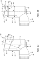
- the ring 120 is movable between a locked position 124 and an unlocked position 126.
- the locked position 124 is shown in Figure 4A .
- the unlocked position 126 is shown in Figure 4B .
- the ring 120 is inclined towards the base 108. In other words, the ring 120 is upwards at the front end 103 of the sleeve 106 and downwards at the rear end 105 of the sleeve 106.
- the ring 120 may define a ring axis 121.
- the ring axis 121 may extend through a center of the ring 120.
- the ring axis 121 of the ring 120 may define a ring angle ⁇ r relative to the longitudinal axis 110.
- the ring axis 121 can be substantially parallel to the longitudinal axis 110, e.g., the ring angle ⁇ r is about 0 degrees as shown in Figure 4B .
- the ring angle ⁇ r is no greater than about 10 degrees.
- the ring angle ⁇ r may be from about 10 degrees to about 30 degrees.
- the ring angle ⁇ r may be from about 20 degrees to about 30 degrees.
- the clearance fit of the ring 120 relative to the sleeve 106 may be greater than the embodiment illustrated in Figures 3A and 3B .
- the diameter D of the ring 120 may be about 1 mm greater than the width W of the sleeve 106.
- the diameter D of the ring 120 may be about 1.5 mm greater than the width W of the sleeve 106.
- the ring angle ⁇ r of the ring 120 may depend on a clearance between the diameter D of the ring 120 and the width W of the sleeve 106.
- the ring 120 In the locked position 124, the ring 120 is inclined relative to the longitudinal axis 110 and locked with the sleeve 106 to prevent relative movement between the sleeve 106 and the ring 120. In the locked position 124, the ring 120 may be prevented from any substantial rotation or sliding relative to the sleeve 106. In some embodiments, for locking the ring 120 in the locked position 124, there may be a set of protrusions, a set of indents, or any other such structural arrangement at the front end 103 of the sleeve 106. In some embodiments, a coefficient of friction between the ring 120 and the sleeve 106 may be sufficient to keep the 120 in the locked position 124.
- the ring axis 121 is substantially parallel to the longitudinal axis 110 and is both rotatable and slidable relative to the sleeve 106.
- the ring 120 In the unlocked position 126, the ring 120 has a substantial clearance CL with respect to the sleeve 106.
- the ring 120 In order to bring the ring 120 into the unlocked position 126 from the locked position 124, the ring 120 may be lifted up (indicated by an arrow A5 in Figure 4A ) from the rear end 105 of the sleeve 106 in such a manner that the ring axis 121 is substantially parallel to the longitudinal axis 110.
- the ring axis 121 (shown in Figure 4A ) may be substantially parallel to the longitudinal axis 110.
- Users of the inhaler 200 may decide a suitable position for the cover 116 during inhalation.
- the suitable position for users may depend on their hand size, whether they are right-handed, left-handed or ambidextrous, whether they are a "thumb on top” pusher, a "fingers across the top, and thumb underneath” firer, a "hand wrapped round” holder, and/or whether they are a carer administering a dose to another person.
- the cover 116 may be positioned to suit them without the cover 116 becoming lost. Two of the many possible suitable positions are illustrated in Figures 3A and 3B .
- the inhaler 200 is provided.
- the inhaler 200 is shown in Figure 1 .
- the inhaler 200 may be formed by injection moulding of a polyolefin material (e.g., polyethylene or polypropylene).
- the inhaler 200 includes the aforementioned actuator 100.
- the inhaler 200 further includes the canister 202.
- the canister 202 contains a fluid formulated with a medicament.
- the canister 202 is at least partially received within the sleeve 106 of the actuator 100.
- a method of using the inhaler 200 of the present disclosure includes the following steps. The method is explained with reference to Figures 1 , 2 , 3A and 3B .
- the first step includes detaching the cover 116 from the mouthpiece 112 to at least partially expose the delivery opening 114. During this step, the cover 116 is detached from the mouthpiece 112.
- the second step includes rotating the ring 120 relative to the sleeve 106 to move the cover 116 away from the mouthpiece 112. In some cases, the second step further incudes sliding the ring 120 towards the second end 104 of the sleeve 106.
- the ring 120 may be rotated to any user desired position.
- the third step includes actuating the inhaler 200 to deliver the medicament through the delivery opening.
- Actuating the inhaler 200 may include pressing the canister 202 against the base 108 of the sleeve 106 of the actuator 100.
- a method of using the inhaler 200 of the present disclosure includes the following steps. The method is explained with reference to Figures 1 , 2 , 3A, 3B , 4A and 4B .
- the first step includes detaching the cover 116 from the mouthpiece 112 to at least partially expose the delivery opening 114. During this step, the cover 116 is detached from the mouthpiece 112.
- the second step includes lifting the ring 120 from the rear end 105 of the sleeve 106 of the actuator 100 in a manner that the ring axis 121 is substantially parallel to the longitudinal axis 110. In other words, the ring 120 is brought to the unlocked position 126 from the locked position 124.
- the third step includes rotating the ring 120 relative to the sleeve 106 to move the cover 116 away from the mouthpiece 112. In some cases, the third step further incudes sliding the ring 120 towards the second end 104 of the sleeve 106.
- the ring 120 may be rotated to any user desired position.
- the fourth step includes actuating the inhaler 200 to deliver the medicament through the delivery opening.
- Actuating the inhaler 200 may include pressing the canister 202 against the base 108 of the sleeve 106 of the actuator 100.
- the ring 120 may not be completely continuous and may be in segments.
- the disclosure is also equally applicable to Dry Powder Inhalers (DPIs), soft mist inhalers, etc.
Landscapes
- Health & Medical Sciences (AREA)
- Engineering & Computer Science (AREA)
- Biomedical Technology (AREA)
- Bioinformatics & Cheminformatics (AREA)
- Pulmonology (AREA)
- Anesthesiology (AREA)
- Heart & Thoracic Surgery (AREA)
- Hematology (AREA)
- Life Sciences & Earth Sciences (AREA)
- Animal Behavior & Ethology (AREA)
- General Health & Medical Sciences (AREA)
- Public Health (AREA)
- Veterinary Medicine (AREA)
- Mechanical Engineering (AREA)
- Infusion, Injection, And Reservoir Apparatuses (AREA)
Claims (15)
- Aktuator (100) für einen Inhalator (200), wobei der Aktuator (100) aufweist:eine Hülse (106) mit einem ersten Ende (102) und einem zweiten Ende (104), wobei die Hülse (106) im Wesentlichen hohl ist und eine Längsachse (110) entlang ihrer Länge definiert,eine am ersten Ende (102) der Hülse (106) ausgebildete Basis (108);ein mit der Hülse (106) und der Basis (108) verbundenes Mundstück (112), wobei das Mundstück (112) im Wesentlichen hohl ist und eine Abgabeöffnung (114) definiert, undeine abnehmbar am Mundstück (112) befestigte Abdeckung (116) zum Abdecken der Abgabeöffnung (114);dadurch gekennzeichnet, dass der Aktuator (100) aufweist:
ein Halteelement (118) zum Halten der Abdeckung (116) an der Hülse (106) beim Entfernen der Abdeckung (116) vom Mundstück (112), wobei das Halteelement (118) aufweist:einen um die Hülse (106) herum angeordneten Ring (120), wobei der Ring (120) zumindest selektiv um die Längsachse (110) drehbar und entlang der Längsachse (110) relativ zur Hülse (106) verschiebbar ist; undeinen Streifen (122), der sich vom Ring (120) erstreckt und an der Abdeckung (116) befestigt ist. - Aktuator (100) nach Anspruch 1, wobei der Ring (120) eine sich durch eine Mitte des Rings erstreckende Ringachse (121) definiert, wobei die Ringachse (121) sich im Wesentlichen parallel zur Längsachse (110) erstreckt, und wobei ferner der Ring (120) relativ zur Hülse (106) sowohl drehbar als auch verschiebbar ist.
- Aktuator (100) nach Anspruch 1, wobei der Ring (120) zwischen einer verriegelten Position (124) und einer entriegelten Position (126) bewegbar ist, wobei:der Ring (120) in der verriegelten Position (124) relativ zur Längsachse (110) geneigt und mit der Hülse (106) verriegelt ist, um eine Relativbewegung zwischen der Hülse (106) und dem Ring (120) zu verhindern, undder Ring (120) in der entriegelten Position (126) sich im Wesentlichen parallel zur Längsachse (110) erstreckt und relativ zur Hülse (106) sowohl drehbar als auch verschiebbar ist.
- Aktuator (100) nach Anspruch 3, wobei der Ring (120) in der verriegelten Position (124) zur Basis (108) hin geneigt ist.
- Aktuator (100) nach Anspruch 1, wobei das Mundstück (112) relativ zur Längsachse (110) geneigt ist.
- Aktuator (100) nach Anspruch 5, wobei das Mundstück (112) sich im Wesentlichen senkrecht zur Längsachse (110) erstreckt.
- Aktuator (100) nach Anspruch 1, wobei die Hülse (106) ferner einen Vorsprung (107) an ihrem zweiten Ende (104) aufweist, und wobei der Vorsprung (107) relativ zur Längsachse (110) geneigt ist.
- Aktuator (100) nach Anspruch 1, wobei ein Durchmesser (D) des Rings (120) größer ist als eine Breite (W) der Hülse (106).
- Inhalator (200), mit:dem Aktuator (100) nach Anspruch 1; undeinem Behälter (202), der ein mit einem Medikament formuliertes Fluid enthält, wobei der Behälter (202) zumindest teilweise innerhalb der Hülse (106) des Aktuators (100) aufgenommen ist.
- Inhalator (200) nach Anspruch 9, wobei der Ring (120) eine Ringachse (121) definiert, die sich durch eine Mitte des Rings (120) erstreckt, wobei die Ringachse (121) sich im Wesentlichen parallel zur Längsachse (110) erstreckt, und wobei ferner der Ring (120) relativ zur Hülse (106) sowohl drehbar als auch verschiebbar ist.
- Inhalator (200) nach Anspruch 9, wobei der Ring (120) zwischen einer verriegelten Position (124) und einer entriegelten Position (126) bewegbar ist, wobei:der Ring (120) in der verriegelten Position (124) relativ zur Längsachse (110) geneigt und mit der Hülse (106) verriegelt ist, um eine Relativbewegung zwischen der Hülse (106) und dem Ring (120) zu verhindern, undin der entriegelten Position (126) eine Ringachse (121), die durch den Ring (120) definiert ist und sich durch eine Mitte des Rings (120) erstreckt, sich im Wesentlichen parallel zur Längsachse (110) erstreckt und relativ zur Hülse (106) sowohl drehbar als auch verschiebbar ist.
- Inhalator (200) nach Anspruch 11, wobei der Ring (120) in der verriegelten Position (124) zur Basis hin geneigt ist.
- Inhalator (200) nach Anspruch 9, wobei das Mundstück (112) relativ zur Längsachse (110) geneigt ist.
- Inhalator (200) nach Anspruch 13, wobei das Mundstück (112) sich im Wesentlichen senkrecht zur Längsachse (110) erstreckt.
- Inhalator (200) nach Anspruch 9, wobei die Hülse (106) ferner einen Vorsprung (107) an ihrem zweiten Ende (104) aufweist, und wobei der Vorsprung (107) relativ zur Längsachse (10) geneigt ist.
Applications Claiming Priority (2)
| Application Number | Priority Date | Filing Date | Title |
|---|---|---|---|
| US202063017707P | 2020-04-30 | 2020-04-30 | |
| PCT/US2021/029125 WO2021222087A1 (en) | 2020-04-30 | 2021-04-26 | Cover assembly and actuator for inhaler |
Publications (2)
| Publication Number | Publication Date |
|---|---|
| EP4142837A1 EP4142837A1 (de) | 2023-03-08 |
| EP4142837B1 true EP4142837B1 (de) | 2024-03-27 |
Family
ID=75919441
Family Applications (1)
| Application Number | Title | Priority Date | Filing Date |
|---|---|---|---|
| EP21725922.5A Active EP4142837B1 (de) | 2020-04-30 | 2021-04-26 | Abdeckungsanordnung und aktuator für inhalator |
Country Status (4)
| Country | Link |
|---|---|
| US (1) | US20230166056A1 (de) |
| EP (1) | EP4142837B1 (de) |
| CN (1) | CN116056743A (de) |
| WO (1) | WO2021222087A1 (de) |
Family Cites Families (7)
| Publication number | Priority date | Publication date | Assignee | Title |
|---|---|---|---|---|
| AU3439884A (en) * | 1983-11-28 | 1985-06-13 | Vortran Corp. | Single inlet prepackaged inhaler |
| US6257231B1 (en) * | 1998-12-03 | 2001-07-10 | Ferraris Medical, Inc. | Aerosol enhancement |
| GB2364320B (en) * | 2000-07-06 | 2002-06-12 | Bespak Plc | Dispensing apparatus |
| FR2872489B1 (fr) * | 2004-07-01 | 2008-12-12 | Valois Sas | Systeme d'obturation destine a etre monte sur un dispositif de distribution de produit fluide |
| WO2014140765A1 (en) * | 2013-03-15 | 2014-09-18 | Trudell Medical International | Ventilator circuit, adapter for use in ventilator circuit and methods for the use thereof |
| GB201308679D0 (en) * | 2013-05-14 | 2013-06-26 | 3M Innovative Properties Co | Actuator for an inhaler |
| GB2568982A (en) * | 2018-02-05 | 2019-06-05 | Mirror 5 Ltd | Inhaler device |
-
2021
- 2021-04-26 EP EP21725922.5A patent/EP4142837B1/de active Active
- 2021-04-26 US US17/921,777 patent/US20230166056A1/en not_active Abandoned
- 2021-04-26 WO PCT/US2021/029125 patent/WO2021222087A1/en not_active Ceased
- 2021-04-26 CN CN202180031871.8A patent/CN116056743A/zh active Pending
Also Published As
| Publication number | Publication date |
|---|---|
| EP4142837A1 (de) | 2023-03-08 |
| US20230166056A1 (en) | 2023-06-01 |
| WO2021222087A1 (en) | 2021-11-04 |
| CN116056743A (zh) | 2023-05-02 |
Similar Documents
| Publication | Publication Date | Title |
|---|---|---|
| US4227522A (en) | Inhalation device | |
| CA2310224C (en) | Inhalation device | |
| US9498592B2 (en) | Modular pulmonary treatment system | |
| EP2838595B1 (de) | Inhalationsvorrichtung sowie systeme | |
| US7556037B2 (en) | Inhalation aid | |
| RU2177333C2 (ru) | Ингаляционное устройство | |
| CA2221997A1 (en) | Inhaler with collapsible chamber | |
| CN102573972A (zh) | 粉末吸入器 | |
| EP2560716A1 (de) | Inhalator | |
| US20070074718A1 (en) | Metered dose inhaler having spacing device | |
| EP3377157A1 (de) | Verbesserungen an inhalatorvorrichtungen mit abgemessener dosierung | |
| US20040134489A1 (en) | Inhalation device | |
| US20230166056A1 (en) | Cover assembly and actuator for inhaler | |
| WO2011095762A1 (en) | Dispenser | |
| US20220401663A1 (en) | Compact atomizer | |
| EP3551265B1 (de) | Inhalatorgehäuse | |
| WO2020095175A1 (en) | Actuator housing for inhaler device | |
| WO2019150074A1 (en) | Inhaler device | |
| HK1206289B (en) | Inhalation devices and systems and methods including the same | |
| MXPA99008817A (en) | Inhalation device |
Legal Events
| Date | Code | Title | Description |
|---|---|---|---|
| STAA | Information on the status of an ep patent application or granted ep patent |
Free format text: STATUS: UNKNOWN |
|
| STAA | Information on the status of an ep patent application or granted ep patent |
Free format text: STATUS: THE INTERNATIONAL PUBLICATION HAS BEEN MADE |
|
| PUAI | Public reference made under article 153(3) epc to a published international application that has entered the european phase |
Free format text: ORIGINAL CODE: 0009012 |
|
| STAA | Information on the status of an ep patent application or granted ep patent |
Free format text: STATUS: REQUEST FOR EXAMINATION WAS MADE |
|
| 17P | Request for examination filed |
Effective date: 20221119 |
|
| AK | Designated contracting states |
Kind code of ref document: A1 Designated state(s): AL AT BE BG CH CY CZ DE DK EE ES FI FR GB GR HR HU IE IS IT LI LT LU LV MC MK MT NL NO PL PT RO RS SE SI SK SM TR |
|
| DAV | Request for validation of the european patent (deleted) | ||
| DAX | Request for extension of the european patent (deleted) | ||
| GRAP | Despatch of communication of intention to grant a patent |
Free format text: ORIGINAL CODE: EPIDOSNIGR1 |
|
| STAA | Information on the status of an ep patent application or granted ep patent |
Free format text: STATUS: GRANT OF PATENT IS INTENDED |
|
| INTG | Intention to grant announced |
Effective date: 20231006 |
|
| GRAS | Grant fee paid |
Free format text: ORIGINAL CODE: EPIDOSNIGR3 |
|
| GRAA | (expected) grant |
Free format text: ORIGINAL CODE: 0009210 |
|
| STAA | Information on the status of an ep patent application or granted ep patent |
Free format text: STATUS: THE PATENT HAS BEEN GRANTED |
|
| AK | Designated contracting states |
Kind code of ref document: B1 Designated state(s): AL AT BE BG CH CY CZ DE DK EE ES FI FR GB GR HR HU IE IS IT LI LT LU LV MC MK MT NL NO PL PT RO RS SE SI SK SM TR |
|
| REG | Reference to a national code |
Ref country code: GB Ref legal event code: FG4D |
|
| REG | Reference to a national code |
Ref country code: CH Ref legal event code: EP |
|
| REG | Reference to a national code |
Ref country code: DE Ref legal event code: R096 Ref document number: 602021011001 Country of ref document: DE |
|
| REG | Reference to a national code |
Ref country code: IE Ref legal event code: FG4D |
|
| P01 | Opt-out of the competence of the unified patent court (upc) registered |
Effective date: 20240326 |
|
| RAP2 | Party data changed (patent owner data changed or rights of a patent transferred) |
Owner name: KINDEVA DRUG DELIVERY L.P. |
|
| PG25 | Lapsed in a contracting state [announced via postgrant information from national office to epo] |
Ref country code: LT Free format text: LAPSE BECAUSE OF FAILURE TO SUBMIT A TRANSLATION OF THE DESCRIPTION OR TO PAY THE FEE WITHIN THE PRESCRIBED TIME-LIMIT Effective date: 20240327 |
|
| PGFP | Annual fee paid to national office [announced via postgrant information from national office to epo] |
Ref country code: DE Payment date: 20240429 Year of fee payment: 4 |
|
| REG | Reference to a national code |
Ref country code: LT Ref legal event code: MG9D |
|
| PG25 | Lapsed in a contracting state [announced via postgrant information from national office to epo] |
Ref country code: GR Free format text: LAPSE BECAUSE OF FAILURE TO SUBMIT A TRANSLATION OF THE DESCRIPTION OR TO PAY THE FEE WITHIN THE PRESCRIBED TIME-LIMIT Effective date: 20240628 |
|
| PG25 | Lapsed in a contracting state [announced via postgrant information from national office to epo] |
Ref country code: RS Free format text: LAPSE BECAUSE OF FAILURE TO SUBMIT A TRANSLATION OF THE DESCRIPTION OR TO PAY THE FEE WITHIN THE PRESCRIBED TIME-LIMIT Effective date: 20240627 Ref country code: HR Free format text: LAPSE BECAUSE OF FAILURE TO SUBMIT A TRANSLATION OF THE DESCRIPTION OR TO PAY THE FEE WITHIN THE PRESCRIBED TIME-LIMIT Effective date: 20240327 |
|
| PG25 | Lapsed in a contracting state [announced via postgrant information from national office to epo] |
Ref country code: RS Free format text: LAPSE BECAUSE OF FAILURE TO SUBMIT A TRANSLATION OF THE DESCRIPTION OR TO PAY THE FEE WITHIN THE PRESCRIBED TIME-LIMIT Effective date: 20240627 Ref country code: NO Free format text: LAPSE BECAUSE OF FAILURE TO SUBMIT A TRANSLATION OF THE DESCRIPTION OR TO PAY THE FEE WITHIN THE PRESCRIBED TIME-LIMIT Effective date: 20240627 Ref country code: LT Free format text: LAPSE BECAUSE OF FAILURE TO SUBMIT A TRANSLATION OF THE DESCRIPTION OR TO PAY THE FEE WITHIN THE PRESCRIBED TIME-LIMIT Effective date: 20240327 Ref country code: HR Free format text: LAPSE BECAUSE OF FAILURE TO SUBMIT A TRANSLATION OF THE DESCRIPTION OR TO PAY THE FEE WITHIN THE PRESCRIBED TIME-LIMIT Effective date: 20240327 Ref country code: GR Free format text: LAPSE BECAUSE OF FAILURE TO SUBMIT A TRANSLATION OF THE DESCRIPTION OR TO PAY THE FEE WITHIN THE PRESCRIBED TIME-LIMIT Effective date: 20240628 Ref country code: FI Free format text: LAPSE BECAUSE OF FAILURE TO SUBMIT A TRANSLATION OF THE DESCRIPTION OR TO PAY THE FEE WITHIN THE PRESCRIBED TIME-LIMIT Effective date: 20240327 Ref country code: BG Free format text: LAPSE BECAUSE OF FAILURE TO SUBMIT A TRANSLATION OF THE DESCRIPTION OR TO PAY THE FEE WITHIN THE PRESCRIBED TIME-LIMIT Effective date: 20240327 |
|
| PGFP | Annual fee paid to national office [announced via postgrant information from national office to epo] |
Ref country code: FR Payment date: 20240425 Year of fee payment: 4 |
|
| REG | Reference to a national code |
Ref country code: NL Ref legal event code: MP Effective date: 20240327 |
|
| PG25 | Lapsed in a contracting state [announced via postgrant information from national office to epo] |
Ref country code: SE Free format text: LAPSE BECAUSE OF FAILURE TO SUBMIT A TRANSLATION OF THE DESCRIPTION OR TO PAY THE FEE WITHIN THE PRESCRIBED TIME-LIMIT Effective date: 20240327 Ref country code: LV Free format text: LAPSE BECAUSE OF FAILURE TO SUBMIT A TRANSLATION OF THE DESCRIPTION OR TO PAY THE FEE WITHIN THE PRESCRIBED TIME-LIMIT Effective date: 20240327 |
|
| PG25 | Lapsed in a contracting state [announced via postgrant information from national office to epo] |
Ref country code: NL Free format text: LAPSE BECAUSE OF FAILURE TO SUBMIT A TRANSLATION OF THE DESCRIPTION OR TO PAY THE FEE WITHIN THE PRESCRIBED TIME-LIMIT Effective date: 20240327 |
|
| REG | Reference to a national code |
Ref country code: AT Ref legal event code: MK05 Ref document number: 1669328 Country of ref document: AT Kind code of ref document: T Effective date: 20240327 |
|
| PG25 | Lapsed in a contracting state [announced via postgrant information from national office to epo] |
Ref country code: NL Free format text: LAPSE BECAUSE OF FAILURE TO SUBMIT A TRANSLATION OF THE DESCRIPTION OR TO PAY THE FEE WITHIN THE PRESCRIBED TIME-LIMIT Effective date: 20240327 |
|
| PG25 | Lapsed in a contracting state [announced via postgrant information from national office to epo] |
Ref country code: IS Free format text: LAPSE BECAUSE OF FAILURE TO SUBMIT A TRANSLATION OF THE DESCRIPTION OR TO PAY THE FEE WITHIN THE PRESCRIBED TIME-LIMIT Effective date: 20240727 |
|
| PG25 | Lapsed in a contracting state [announced via postgrant information from national office to epo] |
Ref country code: SM Free format text: LAPSE BECAUSE OF FAILURE TO SUBMIT A TRANSLATION OF THE DESCRIPTION OR TO PAY THE FEE WITHIN THE PRESCRIBED TIME-LIMIT Effective date: 20240327 Ref country code: PT Free format text: LAPSE BECAUSE OF FAILURE TO SUBMIT A TRANSLATION OF THE DESCRIPTION OR TO PAY THE FEE WITHIN THE PRESCRIBED TIME-LIMIT Effective date: 20240729 |
|
| PG25 | Lapsed in a contracting state [announced via postgrant information from national office to epo] |
Ref country code: ES Free format text: LAPSE BECAUSE OF FAILURE TO SUBMIT A TRANSLATION OF THE DESCRIPTION OR TO PAY THE FEE WITHIN THE PRESCRIBED TIME-LIMIT Effective date: 20240327 |
|
| PG25 | Lapsed in a contracting state [announced via postgrant information from national office to epo] |
Ref country code: CZ Free format text: LAPSE BECAUSE OF FAILURE TO SUBMIT A TRANSLATION OF THE DESCRIPTION OR TO PAY THE FEE WITHIN THE PRESCRIBED TIME-LIMIT Effective date: 20240327 Ref country code: EE Free format text: LAPSE BECAUSE OF FAILURE TO SUBMIT A TRANSLATION OF THE DESCRIPTION OR TO PAY THE FEE WITHIN THE PRESCRIBED TIME-LIMIT Effective date: 20240327 |
|
| PG25 | Lapsed in a contracting state [announced via postgrant information from national office to epo] |
Ref country code: AT Free format text: LAPSE BECAUSE OF FAILURE TO SUBMIT A TRANSLATION OF THE DESCRIPTION OR TO PAY THE FEE WITHIN THE PRESCRIBED TIME-LIMIT Effective date: 20240327 |
|
| PG25 | Lapsed in a contracting state [announced via postgrant information from national office to epo] |
Ref country code: PL Free format text: LAPSE BECAUSE OF FAILURE TO SUBMIT A TRANSLATION OF THE DESCRIPTION OR TO PAY THE FEE WITHIN THE PRESCRIBED TIME-LIMIT Effective date: 20240327 |
|
| PG25 | Lapsed in a contracting state [announced via postgrant information from national office to epo] |
Ref country code: SK Free format text: LAPSE BECAUSE OF FAILURE TO SUBMIT A TRANSLATION OF THE DESCRIPTION OR TO PAY THE FEE WITHIN THE PRESCRIBED TIME-LIMIT Effective date: 20240327 |
|
| PG25 | Lapsed in a contracting state [announced via postgrant information from national office to epo] |
Ref country code: SM Free format text: LAPSE BECAUSE OF FAILURE TO SUBMIT A TRANSLATION OF THE DESCRIPTION OR TO PAY THE FEE WITHIN THE PRESCRIBED TIME-LIMIT Effective date: 20240327 Ref country code: SK Free format text: LAPSE BECAUSE OF FAILURE TO SUBMIT A TRANSLATION OF THE DESCRIPTION OR TO PAY THE FEE WITHIN THE PRESCRIBED TIME-LIMIT Effective date: 20240327 Ref country code: RO Free format text: LAPSE BECAUSE OF FAILURE TO SUBMIT A TRANSLATION OF THE DESCRIPTION OR TO PAY THE FEE WITHIN THE PRESCRIBED TIME-LIMIT Effective date: 20240327 Ref country code: PT Free format text: LAPSE BECAUSE OF FAILURE TO SUBMIT A TRANSLATION OF THE DESCRIPTION OR TO PAY THE FEE WITHIN THE PRESCRIBED TIME-LIMIT Effective date: 20240729 Ref country code: PL Free format text: LAPSE BECAUSE OF FAILURE TO SUBMIT A TRANSLATION OF THE DESCRIPTION OR TO PAY THE FEE WITHIN THE PRESCRIBED TIME-LIMIT Effective date: 20240327 Ref country code: IS Free format text: LAPSE BECAUSE OF FAILURE TO SUBMIT A TRANSLATION OF THE DESCRIPTION OR TO PAY THE FEE WITHIN THE PRESCRIBED TIME-LIMIT Effective date: 20240727 Ref country code: ES Free format text: LAPSE BECAUSE OF FAILURE TO SUBMIT A TRANSLATION OF THE DESCRIPTION OR TO PAY THE FEE WITHIN THE PRESCRIBED TIME-LIMIT Effective date: 20240327 Ref country code: EE Free format text: LAPSE BECAUSE OF FAILURE TO SUBMIT A TRANSLATION OF THE DESCRIPTION OR TO PAY THE FEE WITHIN THE PRESCRIBED TIME-LIMIT Effective date: 20240327 Ref country code: CZ Free format text: LAPSE BECAUSE OF FAILURE TO SUBMIT A TRANSLATION OF THE DESCRIPTION OR TO PAY THE FEE WITHIN THE PRESCRIBED TIME-LIMIT Effective date: 20240327 Ref country code: AT Free format text: LAPSE BECAUSE OF FAILURE TO SUBMIT A TRANSLATION OF THE DESCRIPTION OR TO PAY THE FEE WITHIN THE PRESCRIBED TIME-LIMIT Effective date: 20240327 |
|
| REG | Reference to a national code |
Ref country code: CH Ref legal event code: PL |
|
| PG25 | Lapsed in a contracting state [announced via postgrant information from national office to epo] |
Ref country code: IT Free format text: LAPSE BECAUSE OF FAILURE TO SUBMIT A TRANSLATION OF THE DESCRIPTION OR TO PAY THE FEE WITHIN THE PRESCRIBED TIME-LIMIT Effective date: 20240327 |
|
| PG25 | Lapsed in a contracting state [announced via postgrant information from national office to epo] |
Ref country code: LU Free format text: LAPSE BECAUSE OF NON-PAYMENT OF DUE FEES Effective date: 20240426 |
|
| REG | Reference to a national code |
Ref country code: BE Ref legal event code: MM Effective date: 20240430 |
|
| PG25 | Lapsed in a contracting state [announced via postgrant information from national office to epo] |
Ref country code: LU Free format text: LAPSE BECAUSE OF NON-PAYMENT OF DUE FEES Effective date: 20240426 Ref country code: IT Free format text: LAPSE BECAUSE OF FAILURE TO SUBMIT A TRANSLATION OF THE DESCRIPTION OR TO PAY THE FEE WITHIN THE PRESCRIBED TIME-LIMIT Effective date: 20240327 |
|
| REG | Reference to a national code |
Ref country code: DE Ref legal event code: R097 Ref document number: 602021011001 Country of ref document: DE |
|
| PG25 | Lapsed in a contracting state [announced via postgrant information from national office to epo] |
Ref country code: MC Free format text: LAPSE BECAUSE OF FAILURE TO SUBMIT A TRANSLATION OF THE DESCRIPTION OR TO PAY THE FEE WITHIN THE PRESCRIBED TIME-LIMIT Effective date: 20240327 |
|
| PG25 | Lapsed in a contracting state [announced via postgrant information from national office to epo] |
Ref country code: DK Free format text: LAPSE BECAUSE OF FAILURE TO SUBMIT A TRANSLATION OF THE DESCRIPTION OR TO PAY THE FEE WITHIN THE PRESCRIBED TIME-LIMIT Effective date: 20240327 |
|
| PG25 | Lapsed in a contracting state [announced via postgrant information from national office to epo] |
Ref country code: BE Free format text: LAPSE BECAUSE OF NON-PAYMENT OF DUE FEES Effective date: 20240430 |
|
| PG25 | Lapsed in a contracting state [announced via postgrant information from national office to epo] |
Ref country code: MC Free format text: LAPSE BECAUSE OF FAILURE TO SUBMIT A TRANSLATION OF THE DESCRIPTION OR TO PAY THE FEE WITHIN THE PRESCRIBED TIME-LIMIT Effective date: 20240327 Ref country code: DK Free format text: LAPSE BECAUSE OF FAILURE TO SUBMIT A TRANSLATION OF THE DESCRIPTION OR TO PAY THE FEE WITHIN THE PRESCRIBED TIME-LIMIT Effective date: 20240327 Ref country code: BE Free format text: LAPSE BECAUSE OF NON-PAYMENT OF DUE FEES Effective date: 20240430 Ref country code: CH Free format text: LAPSE BECAUSE OF NON-PAYMENT OF DUE FEES Effective date: 20240430 |
|
| PLBE | No opposition filed within time limit |
Free format text: ORIGINAL CODE: 0009261 |
|
| STAA | Information on the status of an ep patent application or granted ep patent |
Free format text: STATUS: NO OPPOSITION FILED WITHIN TIME LIMIT |
|
| 26N | No opposition filed |
Effective date: 20250103 |
|
| PG25 | Lapsed in a contracting state [announced via postgrant information from national office to epo] |
Ref country code: IE Free format text: LAPSE BECAUSE OF NON-PAYMENT OF DUE FEES Effective date: 20240426 |
|
| PG25 | Lapsed in a contracting state [announced via postgrant information from national office to epo] |
Ref country code: SI Free format text: LAPSE BECAUSE OF FAILURE TO SUBMIT A TRANSLATION OF THE DESCRIPTION OR TO PAY THE FEE WITHIN THE PRESCRIBED TIME-LIMIT Effective date: 20240327 |
|
| PG25 | Lapsed in a contracting state [announced via postgrant information from national office to epo] |
Ref country code: CY Free format text: LAPSE BECAUSE OF FAILURE TO SUBMIT A TRANSLATION OF THE DESCRIPTION OR TO PAY THE FEE WITHIN THE PRESCRIBED TIME-LIMIT; INVALID AB INITIO Effective date: 20210426 |
|
| PG25 | Lapsed in a contracting state [announced via postgrant information from national office to epo] |
Ref country code: HU Free format text: LAPSE BECAUSE OF FAILURE TO SUBMIT A TRANSLATION OF THE DESCRIPTION OR TO PAY THE FEE WITHIN THE PRESCRIBED TIME-LIMIT; INVALID AB INITIO Effective date: 20210426 |
|
| REG | Reference to a national code |
Ref country code: DE Ref legal event code: R119 Ref document number: 602021011001 Country of ref document: DE |
|
| GBPC | Gb: european patent ceased through non-payment of renewal fee |
Effective date: 20250426 |
|
| PG25 | Lapsed in a contracting state [announced via postgrant information from national office to epo] |
Ref country code: DE Free format text: LAPSE BECAUSE OF NON-PAYMENT OF DUE FEES Effective date: 20251104 |
|
| PG25 | Lapsed in a contracting state [announced via postgrant information from national office to epo] |
Ref country code: GB Free format text: LAPSE BECAUSE OF NON-PAYMENT OF DUE FEES Effective date: 20250426 |
|
| PG25 | Lapsed in a contracting state [announced via postgrant information from national office to epo] |
Ref country code: FR Free format text: LAPSE BECAUSE OF NON-PAYMENT OF DUE FEES Effective date: 20250430 |