EP4142425A1 - Verfahren und vorrichtung zur unterstützung des diskontinuierlichen empfangs von sidelink in einem drahtloskommunikationssystem - Google Patents
Verfahren und vorrichtung zur unterstützung des diskontinuierlichen empfangs von sidelink in einem drahtloskommunikationssystem Download PDFInfo
- Publication number
- EP4142425A1 EP4142425A1 EP21845784.4A EP21845784A EP4142425A1 EP 4142425 A1 EP4142425 A1 EP 4142425A1 EP 21845784 A EP21845784 A EP 21845784A EP 4142425 A1 EP4142425 A1 EP 4142425A1
- Authority
- EP
- European Patent Office
- Prior art keywords
- drx
- terminal
- sci
- sidelink
- timer
- Prior art date
- Legal status (The legal status is an assumption and is not a legal conclusion. Google has not performed a legal analysis and makes no representation as to the accuracy of the status listed.)
- Granted
Links
Images


Classifications
-
- H—ELECTRICITY
- H04—ELECTRIC COMMUNICATION TECHNIQUE
- H04W—WIRELESS COMMUNICATION NETWORKS
- H04W52/00—Power management, e.g. Transmission Power Control [TPC] or power classes
- H04W52/02—Power saving arrangements
- H04W52/0209—Power saving arrangements in terminal devices
- H04W52/0212—Power saving arrangements in terminal devices managed by the network, e.g. network or access point is leader and terminal is follower
- H04W52/0216—Power saving arrangements in terminal devices managed by the network, e.g. network or access point is leader and terminal is follower using a pre-established activity schedule, e.g. traffic indication frame
-
- H—ELECTRICITY
- H04—ELECTRIC COMMUNICATION TECHNIQUE
- H04W—WIRELESS COMMUNICATION NETWORKS
- H04W76/00—Connection management
- H04W76/20—Manipulation of established connections
- H04W76/28—Discontinuous transmission [DTX]; Discontinuous reception [DRX]
-
- H—ELECTRICITY
- H04—ELECTRIC COMMUNICATION TECHNIQUE
- H04L—TRANSMISSION OF DIGITAL INFORMATION, e.g. TELEGRAPHIC COMMUNICATION
- H04L1/00—Arrangements for detecting or preventing errors in the information received
- H04L1/12—Arrangements for detecting or preventing errors in the information received by using return channel
- H04L1/16—Arrangements for detecting or preventing errors in the information received by using return channel in which the return channel carries supervisory signals, e.g. repetition request signals
- H04L1/18—Automatic repetition systems, e.g. Van Duuren systems
- H04L1/1829—Arrangements specially adapted for the receiver end
- H04L1/1854—Scheduling and prioritising arrangements
-
- H—ELECTRICITY
- H04—ELECTRIC COMMUNICATION TECHNIQUE
- H04W—WIRELESS COMMUNICATION NETWORKS
- H04W4/00—Services specially adapted for wireless communication networks; Facilities therefor
- H04W4/70—Services for machine-to-machine communication [M2M] or machine type communication [MTC]
-
- H—ELECTRICITY
- H04—ELECTRIC COMMUNICATION TECHNIQUE
- H04W—WIRELESS COMMUNICATION NETWORKS
- H04W72/00—Local resource management
- H04W72/04—Wireless resource allocation
- H04W72/044—Wireless resource allocation based on the type of the allocated resource
- H04W72/0446—Resources in time domain, e.g. slots or frames
-
- H—ELECTRICITY
- H04—ELECTRIC COMMUNICATION TECHNIQUE
- H04W—WIRELESS COMMUNICATION NETWORKS
- H04W72/00—Local resource management
- H04W72/20—Control channels or signalling for resource management
- H04W72/25—Control channels or signalling for resource management between terminals via a wireless link, e.g. sidelink
-
- H—ELECTRICITY
- H04—ELECTRIC COMMUNICATION TECHNIQUE
- H04W—WIRELESS COMMUNICATION NETWORKS
- H04W72/00—Local resource management
- H04W72/30—Resource management for broadcast services
-
- H—ELECTRICITY
- H04—ELECTRIC COMMUNICATION TECHNIQUE
- H04W—WIRELESS COMMUNICATION NETWORKS
- H04W76/00—Connection management
- H04W76/10—Connection setup
- H04W76/14—Direct-mode setup
-
- H—ELECTRICITY
- H04—ELECTRIC COMMUNICATION TECHNIQUE
- H04W—WIRELESS COMMUNICATION NETWORKS
- H04W4/00—Services specially adapted for wireless communication networks; Facilities therefor
- H04W4/30—Services specially adapted for particular environments, situations or purposes
- H04W4/40—Services specially adapted for particular environments, situations or purposes for vehicles, e.g. vehicle-to-pedestrians [V2P]
-
- H—ELECTRICITY
- H04—ELECTRIC COMMUNICATION TECHNIQUE
- H04W—WIRELESS COMMUNICATION NETWORKS
- H04W72/00—Local resource management
- H04W72/02—Selection of wireless resources by user or terminal
-
- H—ELECTRICITY
- H04—ELECTRIC COMMUNICATION TECHNIQUE
- H04W—WIRELESS COMMUNICATION NETWORKS
- H04W92/00—Interfaces specially adapted for wireless communication networks
- H04W92/16—Interfaces between hierarchically similar devices
- H04W92/18—Interfaces between hierarchically similar devices between terminal devices
-
- Y—GENERAL TAGGING OF NEW TECHNOLOGICAL DEVELOPMENTS; GENERAL TAGGING OF CROSS-SECTIONAL TECHNOLOGIES SPANNING OVER SEVERAL SECTIONS OF THE IPC; TECHNICAL SUBJECTS COVERED BY FORMER USPC CROSS-REFERENCE ART COLLECTIONS [XRACs] AND DIGESTS
- Y02—TECHNOLOGIES OR APPLICATIONS FOR MITIGATION OR ADAPTATION AGAINST CLIMATE CHANGE
- Y02D—CLIMATE CHANGE MITIGATION TECHNOLOGIES IN INFORMATION AND COMMUNICATION TECHNOLOGIES [ICT], I.E. INFORMATION AND COMMUNICATION TECHNOLOGIES AIMING AT THE REDUCTION OF THEIR OWN ENERGY USE
- Y02D30/00—Reducing energy consumption in communication networks
- Y02D30/70—Reducing energy consumption in communication networks in wireless communication networks
Definitions
- the disclosure relates to a wireless mobile communication system and, in particular, to a method and device for performing discontinuous reception (DRX) in a process that a vehicle terminal supporting vehicle-to-everything (V2X) transmits and receives information with another vehicle terminal and a pedestrian portable terminal through a sidelink.
- DRX discontinuous reception
- the 5G or pre-5G communication system is also called a ⁇ Beyond 4G Network' or a ⁇ Post long term evolution (LTE) System'.
- the 5G communication system is considered to be implemented in extremely high frequency (mmWave) bands, e.g., 60 GHz band, so as to accomplish higher data rates.
- mmWave extremely high frequency
- cloud RAN cloud radio access network
- D2D device-to-device
- SWSC sliding window superposition coding
- ACM advanced coding modulation
- FBMC filter bank multi carrier
- NOMA non-orthogonal multiple access
- SCMA sparse code multiple access
- the Internet which is a human centered connectivity network where humans generate and consume information
- IoT Internet of things
- IoE Internet of everything
- sensing technology wired/wireless communication and network infrastructure, service interface technology, and security technology
- M2M machine-to-machine
- MTC machine type communication
- IoT environment may provide intelligent Internet technology services that create a new value to human life by collecting and analyzing data generated among connected things.
- IoT may be applied to a variety of fields including smart home, smart building, smart city, smart car or connected cars, smart grid, health care, smart appliances and advanced medical services through convergence and combination between existing information technology (IT) and various industrial applications.
- technologies such as a sensor network, machine type communication (MTC), and machine-to-machine (M2M) communication may be implemented by beamforming, MIMO, and array antennas.
- MTC machine type communication
- M2M machine-to-machine
- Application of a cloud radio access network (cloud RAN) as the above-described big data processing technology may also be considered to be as an example of convergence between the 5G technology and the IoT technology.
- the disclosure relates to a wireless communication system and to a method and device for selecting transmission resources through cooperation between terminals in a process that a vehicle terminal supporting V2X exchanges information with another vehicle terminal and a pedestrian portable terminal through a sidelink. Specifically, the disclosure relates to operations of a base station and a terminal for supporting discontinuous reception (DRX) between terminals.
- DRX discontinuous reception
- a method of a first terminal in a wireless communication system may include receiving sidelink control information (SCI) from a second terminal in an active time of discontinuous reception (DRX); receiving sidelink data from the second terminal based on the SCI; operating a first timer based on the SCI; starting a second timer in response to expiration of the first timer; and receiving retransmission for the sidelink data from the second terminal at a time when the second timer operates, wherein the first terminal may operate with the active time of the DRX while the second timer operates, and a value of the first timer may be determined based on information indicating a time resource related to the retransmission of the sidelink data included in the SCI.
- SCI sidelink control information
- DRX active time of discontinuous reception
- DRX configuration for groupcast communication or broadcast communication may be configured based on a system information block (SIB) received from a base station.
- SIB system information block
- DRX configuration for groupcast communication or broadcast communication may be configured based on information pre-configured in the first terminal.
- DRX configuration for unicast communication may be configured based on inter-terminal radio resource control (PC5-RRC) signaling.
- PC5-RRC inter-terminal radio resource control
- the SCI may include first SCI transmitted in a PSCCH and second SCI transmitted in a PSSCH, and the first terminal may operate with the active time of the DRX during operation of a third timer that starts in response to reception of the first SCI and the second SCI.
- a first terminal in a wireless communication system may include a transceiver; and a controller configured to receive sidelink control information (SCI) from a second terminal in an active time of discontinuous reception (DRX), to receive sidelink data from the second terminal based on the SCI, to operate a first timer based on the SCI, to start a second timer in response to expiration of the first timer, and to receive retransmission for the sidelink data from the second terminal at a time when the second timer operates, wherein the first terminal may operate with the active time of the DRX while the second timer operates, and a value of the first timer may be determined based on information indicating a time resource related to the retransmission of the sidelink data included in the SCI.
- SCI sidelink control information
- DRX active time of discontinuous reception
- a method of a second terminal in a wireless communication system may include transmitting sidelink control information (SCI) to a first terminal, in which discontinuous reception (DRX) is configured, in an active time of the DRX; transmitting sidelink data to the first terminal according to the SCI; and transmitting retransmission of the sidelink data to the first terminal in a time when a second timer of the first terminal operates, wherein the second timer may be started in response to expiration of a first timer operating based on the SCI, and a value of the first timer may be determined based on information indicating a time resource related to the retransmission of the sidelink data included in the SCI.
- SCI sidelink control information
- DRX discontinuous reception
- a second terminal in a wireless communication system may include a transceiver; and a controller configured to transmit sidelink control information (SCI) to a first terminal, in which discontinuous reception (DRX) is configured, in an active time of the DRX, to transmit sidelink data to the first terminal according to the SCI, and to transmit retransmission of the sidelink data to the first terminal in a time when a second timer of the first terminal operates, wherein the second timer may be started in response to expiration of a first timer operating based on the SCI, and a value of the first timer may be determined based on information indicating a time resource related to the retransmission of the sidelink data included in the SCI.
- SCI sidelink control information
- DRX discontinuous reception
- the disclosure proposes a procedure for performing discontinuous reception (DRX) between terminals in sidelink communication.
- the proposed method can be applied and effectively used to minimize the power consumption of the terminal.
- each block of the flowchart illustrations, and combinations of blocks in the flowchart illustrations may be implemented by computer program instructions.
- These computer program instructions may be provided to a processor of a general purpose computer, special purpose computer, or other programmable data processing apparatus to produce a machine, such that the instructions, which are executed via the processor of the computer or other programmable data processing apparatus, generate means for implementing the functions specified in the flowchart block(s).
- These computer program instructions may also be stored in a computer usable or computer-readable memory that may direct a computer or other programmable data processing apparatus to function in a particular manner, such that the instructions stored in the computer usable or computer-readable memory produce an article of manufacture including instruction means that implement the function specified in the flowchart block(s).
- the computer program instructions may also be loaded onto a computer or other programmable data processing apparatus to cause a series of operational steps to be performed on the computer or other programmable apparatus to produce a computer implemented process such that the instructions that are executed on the computer or other programmable apparatus provide steps for implementing the functions specified in the flowchart block(s).
- each block of the flowchart illustrations may represent a module, segment, or portion of code, which comprises one or more executable instructions for implementing the specified logical function(s).
- the functions noted in the blocks may occur out of the order. For example, two blocks shown in succession may in fact be executed substantially concurrently or the blocks may sometimes be executed in the reverse order, depending upon the functionality involved.
- the term “unit” refers to a software element or a hardware element, such as a field programmable gate array (FPGA) or an application specific integrated circuit (ASIC), which performs a predetermined function.
- FPGA field programmable gate array
- ASIC application specific integrated circuit
- a “unit” does not always have a meaning limited to software or hardware.
- a “unit” may be constructed either to be stored in an addressable storage medium or to execute one or more processors. Therefore, a “unit” includes, for example, software elements, object-oriented software elements, class elements or task elements, processes, functions, properties, procedures, subroutines, segments of a program code, drivers, firmware, micro-codes, circuits, data, database, data structures, tables, arrays, and variables.
- elements and units may be combined into those of a smaller number of elements and units or separated into those of a larger number of elements and units.
- the elements and units may be implemented to operate one or more central processing units (CPUs) within a device or a secure multimedia card.
- the unit may include one or more processors.
- Embodiments of the disclosure will be described herein focusing a wireless access network, i.e., new radio (NR), and a packet core, i.e., a 5G system, a 5G core network, or a next generation (NG) core, according to the 5G mobile communication standard specified by the 3rd generation partnership project (3GPP) which is a mobile communication standardization organization.
- NR new radio
- NG next generation
- 3GPP 3rd generation partnership project
- a network data collection and analysis function which is a network function of collecting, analyzing, and providing data in the 5G network, may be defined so as to support network automation.
- the NWDAF may collect information from the 5G network, store and analyze the collected information, and provide a result of analysis to an unspecified network function (NF). The result of analysis may be used independently in each NF.
- 3GPP standards e.g., 5G, NR, LTE, or similar system standards
- 5G 5G
- NR NR
- LTE Long Term Evolution
- 3GPP standards e.g., 5G, NR, LTE, or similar system standards
- the 5G communication system is designed to enable resources in extremely high frequency (mmWave) bands (e.g., 28 GHz frequency band).
- mmWave extremely high frequency
- FD-MIMO full dimensional MIMO
- array antenna an analog beamforming, large scale antenna techniques, etc.
- the 5G communication system supports various subcarrier spacings such as 15 kHz, 30 kHz, 60 kHz, and 120 kHz, uses a polar coding for a physical control channel, and uses a low density parity check (LDPC) for a physical data channel.
- LDPC low density parity check
- CP-OFDM as well as DFT-S-OFDM are used as a waveform for uplink transmission.
- the LTE supports hybrid ARQ (HARQ) retransmission in units of a transport block (TB), whereas the 5G can additionally support HARQ retransmission based on a code block group (CBG) in which a plurality of code blocks (CBs) are bundled.
- CBG code block group
- CBs code blocks
- cloud RAN cloud radio access network
- D2D device-to-device
- V2X vehicle-to-everything
- CoMP coordinated multi-points
- the Internet which is a human centered connectivity network where humans generate and consume information
- IoT Internet of things
- IoE Internet of everything
- sensing technology wired/wireless communication and network infrastructure, service interface technology, and security technology
- M2M machine-to-machine
- MTC machine type communication
- IoT environment may provide intelligent Internet technology services that create a new value to human life by collecting and analyzing data generated among connected things.
- IoT may be applied to a variety of fields including smart home, smart building, smart city, smart car or connected cars, smart grid, health care, smart appliances and advanced medical services through convergence and combination between existing information technology (IT) and various industrial applications.
- 5G communication systems to IoT networks.
- technologies such as a sensor network, machine type communication (MTC), and machine-to-machine (M2M) communication may be implemented by beamforming, MIMO, and array antennas.
- cloud RAN cloud radio access network
- a great variety of services may be provided to users in the communication system.
- a method and apparatus for providing respective services within the same time interval are required.
- One of such services provided in the 5G communication system is a service that satisfies requirements of low latency and high reliability.
- the NR V2X system supports unicast communication, groupcast (or multicast) communication, and broadcast communication between UEs.
- the NR V2X aims to provide more advanced services such as platooning, advanced driving, extended sensors, and remote driving.
- discontinuous reception (DRX) between UEs may be considered in sidelink communication. Applying the DRX can minimize the power consumption of UE and thereby increase battery efficiency. Specifically, the power consumed in a reception process of UE in a sidelink may be subdivided as follows.
- the UE may not perform decoding on the control information and data information.
- the UE may perform decoding on the control information and data information only in a time interval configured as on-duration by applying DRX.
- the disclosure proposes methods of defining off-duration and on-duration for DRX.
- the disclosure proposes methods for enabling the UE performing communication in the sidelink to perform DRX by matching off-duration and on-duration for the DRX.
- Embodiments of the disclosure are proposed to support the above-described scenario, in particular, aiming to provide a method and device for performing discontinuous reception (DRX) between UEs in a sidelink.
- DRX discontinuous reception
- FIGS. 1A to 1D are diagrams illustrating a communication system according to an embodiment of the disclosure.
- FIG. 1A shows an in-coverage (IC) scenario in which all V2X UEs (UE-1 and UE-2) are located within the coverage of a base station. All the V2X UEs are capable of receiving data and control information from the base station through a downlink (DL) or transmitting data and control information to the base station through an uplink (UL). Such data and control information may be available for V2X communication or for general cellular communication. In addition, the V2X UEs are capable of transmitting/receiving data and control information for V2X communication through a sidelink (SL).
- DL downlink
- UL uplink
- DL downlink
- UL uplink
- Such data and control information may be available for V2X communication or for general cellular communication.
- the V2X UEs are capable of transmitting/receiving data and control information for V2X communication through a sidelink (SL).
- SL sidelink
- FIG. 1B shows a scenario in which, among V2X UEs, UE-1 is located within the coverage of the base station and UE-2 is located outside the coverage of the base station. That is, FIG. 1B shows a partial coverage (PC) scenario in which a certain V2X UE (UE-2) is located out of the coverage of the base station.
- the V2X UE-1 located within the coverage of the base station is capable of receiving data and control information from the base station through the downlink or transmitting data and control information to the base station through the uplink.
- the V2X UE-2 located out of the coverage of the base station is incapable of receiving data and control information from the base station through the downlink and incapable of transmitting data and control information to the base station through the uplink.
- the V2X UE-2 is capable of transmitting/receiving data and control information for V2X communication to/from the UE-1 through the sidelink.
- FIG. 1C shows an out-of-coverage (OOC) scenario in which all V2X UEs are located out of the coverage of the base station. Therefore, the V2X UEs (UE-1 and UE-2) are incapable of receiving data and control information from the base station through the downlink and incapable of transmitting data and control information to the base station through the uplink. The V2X UEs (UE-1 and UE-2) are capable of transmitting/receiving data and control information for V2X communication through the sidelink.
- OOC out-of-coverage
- FIG. 1D shows an inter-cell scenario in which V2X UEs (UE-1 and UE-2) located in different cells perform V2X communication with each other.
- FIG. 1D shows a case where the V2X UEs (UE-1 and UE-2) are connected to different base stations (an RRC connected state) or are camping on (an RRC connection released state, i.e., an RRC idle state).
- the V2X UE-1 may be a V2X transmitting UE
- the V2X UE-2 may be a V2X receiving UE.
- the V2X UE-1 may be the V2X receiving UE
- the V2X UE-2 may be the V2X transmitting UE.
- the V2X UE-1 may receive a system information block (SIB) from a base station which the V2X UE-1 is connected to (or is camping on), and the V2X UE-2 may receive the SIB from another base station which the V2X UE-2 is connected to (is camping on).
- SIB system information block
- an existing SIB or an SIB defined separately for V2X may be used as the SIB.
- information of the SIB received by the V2X UE-1 and information of the SIB received by the V2X UE-2 may be different from each other. Therefore, to enable V2X communication between UEs (UE-1 and UE-2) located in different cells, information needs to be unified, or a method of interpreting SIB information transmitted from the other cell through signaling of information may be additionally required.
- FIGS. 1A to 1D illustrate a V2X system composed of two V2X UEs (UE-1 and UE-2) for convenience of description, this is not a limited thereto and communication between more V2X UEs may be performed.
- an interface an uplink and a downlink
- a base station and a V2X UE may be referred to as a Uu interface
- a sidelink between V2X UEs may be referred to as a PC5 interface. Therefore, in the disclosure, the above terms may be used interchangeably.
- the UE may include a vehicle that supports vehicle-to-vehicle (V2V) communication, a vehicle or a pedestrian's handset (e.g., a smartphone) that supports vehicle-to-pedestrian (V2P) communication, a vehicle that supports vehicle-to-network (V2N) communication, or a vehicle that supports vehicle-to-infrastructure (V2I) communication.
- the UE may include a road side unit (RSU) having a UE function, an RSU having a base station function, or an RSU having a part of the base station function and a part of the UE function.
- RSU road side unit
- a base station may be a base station that supports both V2X communication and general cellular communication, or a base station that supports only V2X communication.
- the base station may be a 5G base station (gNB), a 4G base station (eNB), or an RSU. Therefore, in the disclosure, the base station may be referred to as the RSU.
- FIGS. 2A and 2B are diagrams illustrating a V2X communication method performed through a sidelink according to an embodiment of the disclosure.
- a UE-1 201 e.g., a TX UE
- a UE-2 202 e.g., an RX UE
- TX UEs and RX UEs may perform one-to-many communication, which may be referred to as groupcast or multicast communication.
- a UE-1 211, a UE-2 212, and a UE-3 213 form one group (group A) and perform groupcast communication
- a UE-4 214, a UE-5 215, a UE-6 216, and a UE-7 217 form another group (group B) and perform groupcast communication.
- Each UE performs groupcast communication only within a group to which it belongs, and communication between groups may be performed via unicast, groupcast, or broadcast communication.
- FIG. 2B illustrates two groups (group A and group B), this is not a limitation.
- V2X UEs may perform broadcast communication.
- the broadcast communication refers to a case where all V2X UEs receive data and control information transmitted by a V2X transmitting UE through a sidelink.
- the UE-1 211 is a transmitting UE for broadcast
- all the other UEs can receive data and control information transmitted by the UE-1211.
- the NR V2X may consider supporting a form in which a vehicle UE transmits data to only one specific node through unicast and a form in which a vehicle UE transmits data to a specific number of nodes through groupcast.
- these unicast and groupcast technologies can be usefully used in a service scenario such as platooning, which is a technology for moving two or more vehicles connected in a single network in a cluster form.
- platooning is a technology for moving two or more vehicles connected in a single network in a cluster form.
- unicast communication may be required for a leader node of a group connected by platooning to control one specific node
- groupcast communication may be required for simultaneously controlling a group composed of a number of specific nodes.
- FIG. 3 is a diagram illustrating a resource pool defined as a set of resources in time and frequency domains used for sidelink transmission and reception according to an embodiment of the disclosure.
- a resource granularity of the time axis may be a slot.
- a resource granularity of the frequency axis may be a sub-channel composed of one or more physical resource blocks (PRBs).
- PRBs physical resource blocks
- a colored region indicates a region configured as the resource pool in time and frequency domains.
- the resource pool may also be continuously allocated in time domain.
- the disclosure describes an example in which the resource pool is continuously allocated in frequency domain, a method of discontinuously allocating the resource pool in frequency domain is not excluded.
- a case 320 that the resource pool is discontinuously allocated in time domain is illustrated.
- the granularity of time domain resource allocation is a slot.
- one slot composed of a plurality of OFDM symbols may be a basic unit of resource allocation on the time axis.
- all OFDM symbols constituting the slot may be used for sidelink transmission, or some of OFDM symbols constituting the slot may be used for sidelink transmission.
- the others of OFDM symbols constituting of the slot may be used for the downlink/uplink used as the Uu interface between the base station and the UE.
- a colored slot indicates a slot included in a resource pool based on time, and this slot allocated to the resource pool may be (pre-)configured with resource pool information in time domain.
- (pre-)configuration may refer to configuration information pre-configured in the UE and stored in advance, or may refer to a case in which the UE is configured in a cell-common scheme from the base station.
- the cell-common scheme may mean that UEs belonging to a cell receive the same information configuration from the base station.
- a method that the UE receives a sidelink system information block (SL-SIB) from the base station and acquires cell-common information may be considered.
- SIB sidelink system information block
- UE-specific may be replaced with the term UE-dedicated, and it may mean that each UE receives configuration information with a specific value.
- a method that the UE receives an RRC message from the base station and acquires UE-specific information may be considered.
- a physical slot 320 belonging to a resource pool that is non-contiguous in time domain may be mapped to a logical slot 321.
- a set of slots belonging to a physical sidelink shared channel (PSSCH) resource pool may be represented by (t0, t1, ..., ti, ..., tTmax).
- Resource allocation on the frequency axis may be performed in units of sub-channel 331 in a sidelink bandwidth part (BWP).
- the sub-channel 331 may be defined as the granularity of frequency domain resource allocation composed of one or more RBs. That is, the sub-channel 331 may be defined as an integer multiple of RB.
- the sub-channel 331 may be composed of five consecutive PRBs, and the size of the sub-channel (sizeSubchannel) may be the size of five consecutive PRBs.
- sizeSubchannel size of the sub-channel
- One sub-channel may be composed of consecutive PRBs, but it is not necessarily composed of consecutive PRBs.
- the sub-channel 331 may be a basic unit of resource allocation for the PSSCH.
- the startRB-Subchannel 332 may indicate a start position of the sub-channel 331 on the frequency axis in the resource pool.
- resources may be allocated in frequency domain through configuration information on the RB index (startRB-Subchannel, 332) for start of the sub-channel 331, the number (sizeSubchannel) of RBs constituting the sub-channel 331, and the total number (numSubchannel) of sub-channels 331, etc.
- startRB-Subchannel, sizeSubchannel, and numSubchannel may be (pre-)configured as frequency domain resource pool information.
- FIG. 4 is a diagram illustrating a method for a base station to allocate a transmission resource in a sidelink according to an embodiment of the disclosure.
- Mode 1 may be a scheduled resource allocation.
- Mode 1 may indicate a method in which the base station allocates resources used for sidelink transmission to RRC-connected UEs in a dedicated scheduling scheme.
- the method of Mode 1 can be effective for interference management and resource pool management because the base station can manage sidelink resources.
- a transmitting UE 401 which is camping on (405)
- a receiving UE 402 may receive a sidelink system information block (SL-SIB) from a base station (gNB) 403 (step 410).
- the receiving UE 402 indicates a UE receiving data transmitted by the transmitting UE 401.
- the SL-SIB information may include sidelink resource pool information for sidelink transmission/reception, parameter configuration information for sensing operation, information for configuring sidelink synchronization, or carrier information for sidelink transmission/reception operating at different frequencies.
- the transmitting UE 401 may be RRC-connected to the base station 403 (step 420).
- the RRC connection between the UE and the base station may be referred to as Uu-RRC.
- the Uu-RRC connection process 420 may be performed before the data traffic generation of the transmitting UE 401.
- the transmitting UE 401 may perform transmission to the receiving UE 402 via the sidelink. Contrary to this, in Mode 1, the transmitting UE 401 can perform transmission to the receiving UE 402 through the sidelink even in a state where the Uu-RRC connection process 420 between the base station 403 and the receiving UE 402 is not performed.
- the transmitting UE 401 may request a transmission resource capable of performing V2X communication with the receiving UE 402 from the base station 403 (step 430).
- the transmitting UE 401 may request a sidelink transmission resource from the base station 403.
- the MAC CE may be a buffer status report (BSR) MAC CE of a new format (including at least an indicator indicating the BSR for V2X communication and information on the size of data buffered for D2D communication).
- BSR buffer status report
- the transmitting UE 401 may request a sidelink resource through a scheduling request (SR) bit transmitted through the physical uplink control channel.
- SR scheduling request
- the base station 403 may allocate a V2X transmission resource to the transmission UE 401.
- the base station may allocate the transmission resource in a dynamic grant or configured grant scheme.
- the base station may allocate a resource for TB transmission through downlink control information (DCI).
- DCI downlink control information
- Sidelink scheduling information contained in the DCI may include parameters related to transmission occasion and frequency allocation location information fields of initial transmission and retransmission.
- the DCI for the dynamic grant scheme may include a cyclic redundancy check (CRC) scrambled with SL-V-RNTI to indicate the dynamic grant scheme.
- CRC cyclic redundancy check
- the DCI for the dynamic grant scheme may be CRC-scrambled with SL-V-RNTI to indicate the dynamic grant scheme.
- the base station may periodically allocate resources for TB transmission by configuring a semi-persistent scheduling (SPS) interval through Uu-RRC.
- SPS semi-persistent scheduling
- the base station may allocate resources for one TB through the DCI.
- the sidelink scheduling information for one TB contained in the DCI may include parameters related to transmission occasion and frequency allocation location information of initial transmission and retransmission resources.
- the transmission occasion and frequency allocation location of the initial transmission and retransmission for one TB can be determined by the DCI, and the resource for the next TB may be repeated at the SPS interval.
- the DCI for the configured grant scheme may be CRC-scrambled with SL-SPS-V-RNTI to indicate the configured grant scheme.
- the configured grant (CG) scheme may be divided into type! CG and type2 CG. In case of Type2 CG, it is possible to activate/deactivate a resource configured with the configured grant through the DCI.
- the base station 403 may instruct the transmitting UE 401 to schedule for sidelink communication with the receiving UE 402 through DCI transmission via the PDCCH (step 440).
- DCI downlink control information
- DCI format 3_0 may be defined as DCI for scheduling an NR sidelink in one cell
- DCI format 3_1 may be defined as DCI for scheduling an LTE sidelink in one cell.
- DCI format 3_0 includes the following information and may be indicated by the base station 403 to the transmitting UE 401.
- the UE may receive the DCI format 3_0 from the base station and grasp scheduling information for sidelink transmission.
- information that can be included in DCI format 3_0 is not limited to the above-described information.
- the transmitting UE 401 may perform transmission without RRC setup 415 for the sidelink. Contrary to this, in case of unicast or groupcast transmission, the transmitting UE 401 may perform RRC connection with another UE on a one-to-one basis.
- the RRC connection between UEs may be referred to as PC5-RRC 415 to be distinguished from Uu-RRC.
- the PC5-RRC 415 may be individually connected between UEs in a group.
- the connection of the PC5-RRC 415 is shown as an operation after the transmission 410 of the SL-SIB, it may be performed at any time before the transmission 410 of the SL-SIB or before the transmission of the SCI.
- the transmitting UE 401 may transmit 1 st stage SCI to the receiving UE 402 through the PSCCH (step 460).
- the transmitting UE 401 may transmit 2 nd stage SCI to the receiving UE 402 through the PSSCH (step 470).
- the 1 st stage SCI may contain information related to resource allocation, and the 2 nd stage SCI may contain other control information.
- the transmitting UE 401 may transmit data to the receiving UE 402 through the PSSCH (step 480).
- the 1 st stage SCI, the 2 nd stage SCI, and the PSSCH may be transmitted together in the same slot.
- FIG. 5 is a diagram illustrating a method for a UE to directly allocate a sidelink transmission resource through sensing in a sidelink according to an embodiment of the disclosure.
- Mode 2 a method for the UE to directly allocate the sidelink transmission resource through sensing in the sidelink will be referred to as Mode 2.
- Mode 2 it may also be referred to as UE autonomous resource selection.
- a base station 503 may provide a sidelink transmission/reception resource pool for V2X as system information, and a transmitting UE 501 may select a transmission resource in accordance with a predetermined rule.
- the transmitting UE 501 autonomously selects resources and transmits data based on a resource pool previously received through the system information.
- the transmitting UE 501 which is camping on (505), and a receiving UE 502 may receive a SL-SIB from the base station 503 (step 510).
- the receiving UE 502 indicates a UE receiving data transmitted by the transmitting UE 501.
- the SL-SIB information may include sidelink resource pool information for sidelink transmission/reception, parameter configuration information for sensing operation, information for configuring sidelink synchronization, or carrier information for sidelink transmission/reception operating at different frequencies.
- FIG. 4 A difference between FIG. 4 and FIG. 5 is that in FIG. 4 the base station 503 and the transmitting UE 501 operate in an RRC connected state, whereas in FIG. 5 the transmitting UE 501 may operate even in an idle mode 520 (in a state where RRC is not connected). Also, even in the RRC connected state 520, the base station 503 does not directly participate in resource allocation and may allow the transmitting UE 501 to autonomously select a transmission resource.
- the RRC connection between the transmitting UE 501 and the base station 503 may be referred to as Uu-RRC 520.
- the transmitting UE 501 may be configured with a resource pool through the system information received from the base station 503, and the transmitting UE 501 may directly select a resource in the time/frequency domain through sensing within the configured resource pool (step 530). When the resource is finally selected, the selected resource is determined as a grant for sidelink transmission.
- the transmitting UE 501 may perform transmission without RRC setup 515 for the sidelink. Contrary to this, in case of unicast or groupcast transmission, the transmitting UE 501 may perform RRC connection with another UE on a one-to-one basis.
- the RRC connection between UEs may be referred to as PC5-RRC 515 to be distinguished from Uu-RRC.
- the PC5-RRC 515 may be individually connected between UEs in a group.
- the connection of the PC5-RRC 515 is shown as an operation after the transmission 510 of the SL-SIB, it may be performed at any time before the transmission 510 of the SL-SIB or before the transmission of the SCI.
- the transmitting UE 501 may transmit 1 st stage SCI to the receiving UE 502 through the PSCCH (step 550).
- the transmitting UE 501 may transmit 2 nd stage SCI to the receiving UE 502 through the PSSCH (step 560).
- the 1 st stage SCI may contain information related to resource allocation, and the 2 nd stage SCI may contain other control information.
- the transmitting UE 501 may transmit data to the receiving UE 502 through the PSSCH (step 570).
- the 1 st stage SCI, the 2 nd stage SCI, and the PSSCH may be transmitted together in the same slot.
- sidelink control information (SCI) used by the transmitting UEs 401 and 501 for sidelink communication with the receiving UEs 402 and 502 may be SCI format 1-A as the 1 st stage SCI.
- SCI format 2-A or SCI format 2-B as the 2 nd stage SCI.
- SCI format 2-A may be used to include information for PSSCH decoding when HARQ feedback is not used or when HARQ feedback is used and includes both ACK and NACK information.
- SCI format 2-B may be used to include information for PSSCH decoding when HARQ feedback is not used or when HARQ feedback is used and includes only NACK information.
- SCI format 2-B may be limitedly used for groupcast transmission.
- SCI format 1-A may contain the following information and be indicated by the transmitting UEs 401 and 501 to the receiving UEs 402 and 502.
- SCI format 2-A may contain the following information and be indicated by the transmitting UEs 401 and 501 to the receiving UEs 402 and 502.
- SCI format 2-B may contain the following information and be indicated by the transmitting UEs 401 and 501 to the receiving UEs 402 and 502.
- information that can be contained in SCI format 1-A, SCI format 2-A, and SCI format 2-B is not limited to the above-described information.
- FIG. 6 is a diagram illustrating a mapping structure of physical channels mapped to one slot in a sidelink according to an embodiment of the disclosure.
- FIG. 6 shows mapping to PSCCH/PSSCH/PSFCH physical channels.
- PSCCH/PSSCH/PSFCH may be allocated to one or more sub-channels in frequency domain. For details on sub-channel allocation, the description of FIG. 3 is referred to.
- one or more symbols before a transmitting UE transmits PSCCH/PSSCH/PSFCH in a slot 601 may be used a region 602 for automatic gain control (AGC).
- AGC automatic gain control
- a preamble may be transmitted in the AGC region.
- the preamble signal is transmitted, there is an advantage that an AGC execution time can be further shortened compared to the method for repetition transmission of other channel signal.
- a preamble signal is transmitted for the AGC, a specific sequence may be used as the preamble signal 602, and in this case, a sequence such as PSSCH DMRS, PSCCH DMRS, CSI-RS, etc. may be used as the preamble.
- the sequence used as the preamble is not limited to the above examples. Additionally, according to FIG.
- a PSCCH 603 containing control information is transmitted in early symbols of the slot, and data scheduled by the control information of the PSCCH 603 may be transmitted through a PSSCH 604.
- a part (1st stage SCI) of sidelink control information (SCI), which is control information, may be mapped to and transmitted via the PSCCH 603.
- Another part (2nd stage SCI) of the SCI, which is control information, as well as data may be mapped to and transmitted via the PSSCH 604.
- FIG. 6 shows that a physical sidelink feedback channel (PSFCH) 605, which is a physical channel for transmitting feedback information, is located in the last part of the slot.
- PSFCH physical sidelink feedback channel
- a certain empty time (gap) between the PSSCH 604 and the PSFCH 605 may be secured so that a UE that has transmitted or received the PSSCH 604 can prepare to transmit or receive the PSFCH 605. Also, after transmission and reception of the PSFCH 605, another empty time (gap) may be secured.
- FIGS. 7A to 7D are diagrams showing off-duration and on-duration of DRX determined depending on parameters configured for DRX when discontinuous reception (hereinafter, DRX) is performed in a sidelink according to an embodiment of the disclosure.
- DRX on-duration may also be referred to as an active time for DRX.
- the UE may perform decoding on control information and data information in a section corresponding to on-duration of DRX. In contrast, the UE may not perform decoding on control information and data information in a section corresponding to off-duration of DRX.
- data information may be transmitted through the PSSCH. It may be assumed that control information and data information are always transmitted simultaneously in the sidelink. Therefore, a time point at which control information is received may be equal to a time point at which data information is received.
- the following may be considered as parameters for determining off-duration and on-duration for DRX of the sidelink.
- the parameters for determining the off-duration and on-duration of DRX are not limited to the parameters given below. Also, some of the parameters below may not be used in sidelink DRX.
- FIG. 7A illustrated is an example in which off-duration and on-duration of DRX are determined through drx-cycle and drx-onDurationTimer.
- a time interval from the start of the drx-onDurationTimer 702 to the expiration is configured as on-duration 710 of DRX, and the UE may receive sidelink control information during the time interval corresponding to the on-duration 710.
- the remaining drx-cycle interval from the expiration of the drx-onDurationTimer 702 is configured as off-duration 711 of DRX, and the UE may not receive control and data information during the time interval corresponding to the off-duration 711.
- FIG. 7B illustrated is an example in which off-duration and on-duration of DRX are determined through drx-cycle, drx-onDurationTimer, and drx-InactivityTimer.
- a time interval from the start of the drx-onDurationTimer 702 to the expiration is configured as the on-duration 710 of DRX, and the UE may receive sidelink control information during the time interval corresponding to the on-duration 710.
- the DRX on-duration 710 may be extended during a time interval in which the drx-InactivityTimer 704 started at that time point expires. If sidelink control information is not received until the end of the DRX on-duration 710, the remaining drx-cycle interval is configured as the off-duration 711 of DRX, and the UE may not receive control and data information during the time interval corresponding to the off-duration 711.
- FIG. 7C illustrated is an example in which off-duration and on-duration of DRX are determined using drx-HARQ-RTT-Timer and drx-HARQ-RTT-Timer.
- a time interval from the start of the drx-onDurationTimer 702 to the expiration is configured as the on-duration 710 of DRX, and the UE may receive sidelink control information during the time interval corresponding to the on-duration 710.
- the DRX on-duration 710 may be extended during a time interval in which the drx-InactivityTimer 704 started at that time point expires. If sidelink control information is not received until the end of the DRX on-duration 710, the remaining drx-cycle interval is configured as the off-duration 711 of DRX, and the UE may not receive control and data information during the time interval corresponding to the off-duration 711.
- information related to retransmission may be included as control information (refer to the control information included in the 1 st SCI described above). Specifically, information on whether a retransmission resource is reserved and location information of a resource in which the retransmission resource is to be transmitted may be included.
- a time gap between initial transmission and retransmission resources or a time gap between retransmission resources included in the control information may be configured with a drx-HARQ-RTT-Timer 705.
- the drx-RetransmissionTimer 706 may operate. Also, in the sidelink, the drx-RetransmissionTimer may be configured assuming a fixed value of one slot or one subframe. However, the disclosure is not limited to the above. That is, in the sidelink, the drx-RetransmissionTimer may be configured as one or more slots or one or more subframes. As shown in FIG. 7C , the interval in which the drx-RetransmissionTimer 706 operates is configured as the on-duration 712 of DRX, so that the UE can receive retransmitted data. In addition, the remaining drx-cycle interval is configured as the off-duration 713 of DRX, and the UE may not receive control and data information during the time interval corresponding to the off-duration 713.
- a cycle in which the WUS is transmitted may be configured.
- the UE may perform monitoring 707 for the WUS at a location where the WUS is transmitted.
- the UE does not operate the drx-onDurationTimer 702 in the drx-cycle 701 and the entire drx-cycle interval is configured as the off-duration 710 of DRX so that the UE may not receive control and data information.
- the WUS indicates in 707 that the UE wakes up, the UE may perform the operation shown in FIG. 7A , FIG. 7B , or FIG. 7C depending on the configured DRX parameter.
- Proposed in the first embodiment below are a configuration relationship between a resource pool and parameters necessary for performing discontinuous reception (hereinafter referred to as DRX) in the sidelink, a time interval configuration method of the DRX parameters, and methods for determining a start position to which the DRX cycle is applied.
- DRX discontinuous reception
- various methods for enabling the DRX-related parameters to be aligned between sidelink UEs are proposed.
- a DRX operation method in consideration of sensing and resource selection operations in the sidelink Mode2 operation is proposed.
- a DRX operation method is proposed in the case that inter-UE coordination is performed in the sidelink. Note that the following embodiments may be used in combination with each other in the disclosure.
- DRX discontinuous reception
- a time interval configuration method of the DRX parameters and methods for determining a start position to which the DRX cycle is applied are proposed.
- DRX parameters to be considered refer to the DRX-related parameters described above. Note that the off-duration and on-duration of the sidelink DRX may vary according to the proposed methods.
- the off-duration and on-duration of DRX may be determined differently depending on the configuration relationship between DRX-related parameters and the sidelink resource pool.
- the resource pool of the sidelink may be a reception pool (RX pool) or a transmission pool (TX pool). Examples of the disclosure are described considering the reception pool (RX pool), but this is not a limitation. That is, the transmission pool (TX pool) may also be considered.
- TX pool For details on the sidelink resource pool, refer to FIG. 3 above.
- a plurality of transmission pools (TX pools) and a plurality of reception pools (RX pools) may be in (pre-)configuration in the UE.
- X (e.g., 8) transmission pools may be configured, and Y (e.g., 16) reception pools may be configured.
- X transmission pools and Y reception pools may be configured for a resource pool that is in configuration in a cell-common or UE-specific manner with the pre-configuration resource pool.
- FIG. 3 is the description of one resource pool, different resource pools may be in (pre-)configuration to different time resource locations within sidelink transmittable slots and different frequency locations within sidelink BWP.
- FIGS. 8A to 8C are diagrams illustrating a mapping structure in which a plurality of resource pools are configured and mapped to time and frequency according to an embodiment of the disclosure.
- FIG. 8A a case in which two resource pools are allocated to different time resource locations is illustrated.
- the following methods may be considered as a configuration relationship between the DRX-related parameters and the sidelink resource pool proposed in this embodiment. Note that the disclosure is not limited to the following methods as the configuration relationship between the DRX-related parameters and the sidelink resource pool. It is also noted that a combination of the following methods may be used.
- the method 1 is a method in which DRX-related parameters are configured per resource pool, and different DRX operations may be made for each resource pool.
- different DRX configurations are made per pool, so that DRX on/off duration may be irregularly generated.
- the method 2 restricts DRX-related parameters to be configured per resource pool group.
- DRX may be activated or deactivated for each resource pool, and a desired DRX parameter configuration may be operated for the DRX-activated resource pool.
- DRX may be activated or deactivated for each resource pool group, and a desired DRX parameter configuration may be operated for the DRX-activated resource pool group.
- DRX parameter configuration When the DRX parameter configuration is operated as in the method 1 or the method 2, there may be various advantages. For example, a case in which a plurality of resource pools are distinctively operated depending on a sidelink service may be considered. In this case, depending on the sidelink service, DRX operation may or may not be necessary, and when the DRX operation is required, DRX off-duration and on-duration may be configured to suit the corresponding service.
- a plurality of resource pools are distinguished at frequency positions within the sidelink BWP as in FIG. 8B or 8C , by operating DRX through the method 1 or the method 2 for the plurality of resource pools, it is possible to control that a specific frequency region is not used in a specific time region.
- DRX may be operated only for a resource pool that is in configuration in a cell-common or UE-specific manner.
- the method 3 is a method in which DRX parameters are configured for all resource pools, and compared to the method 1 or the method 2, DRX operation can be simplified and irregular occurrence of DRX on/off duration can be reduced.
- a method in which DRX-related parameters are configured in a sidelink carrier or configured in a sidelink BWP may be considered.
- One or multiple sidelink BWPs may be defined in the sidelink carrier.
- the carrier may be replaced with the meaning of the cell.
- the following methods may be considered as a time interval configuration method of DRX parameters proposed in this embodiment. Note that the disclosure is not limited to the following methods as the time interval configuration method of DRX parameters. It is also noted that a combination of the following methods may be used.
- the method for configuring a time interval of DRX parameters may be applied to the DRX-related parameters proposed above.
- FIG. 9 For a detailed description of the methods, refer to FIG. 9 .
- the following methods may be considered as a method for determining a start position (drx-StartOffset) to which a DRX cycle is applied, together with the method for configuring the time interval of the DRX parameters. Note that the disclosure is not limited to the following methods for the start position to which the DRX cycle is applied in time. It is also noted that a combination of the following methods may be used.
- Equation 1 it is assumed that drx-cycle is defined as ms, and when a method other than ms is used among the time interval configuration methods of the DRX parameters, the above Equation may be modified.
- Equation 2 it is assumed that the drx-cycle is defined as ms, and when a method other than ms is used among the time interval configuration methods of the DRX parameters, the above Equation may be modified.
- N slot frame For the value of N slot frame , ⁇ , refer to Table 1 below. [Table 1] ⁇ N slot frame , ⁇ 0 10 1 20 2 40 3 80 4 160
- a frame may use a system frame number (SFN) or a direct frame number (DFN), and the DFN may be determined by the following Equation.
- DFN Floor 0.1 * Tcurrent ⁇ Tref ⁇ offsetDFN mod 1024
- SubframeNumber Floor( Tcurrent -TrefoffsetDFN ) mod 10
- Tcurrent, Tref, and offsetDFN may be defined as follows.
- FIGS. 9A to 9H are diagrams showing examples of a method in which DRX is performed in a sidelink, depending on the configuration relationship between a resource pool and DRX parameters, the time interval configuration method of the DRX parameters, and the methods for determining a start position to which the DRX cycle is applied, which are proposed above.
- FIGS. 9A to 9H show only drx-cycle and drx-onDurationTimer among the DRX parameters that can be configured, the parameters are not limited thereto.
- the disclosure is not limited thereto.
- the focus is on the methods 1 and 3 described in the method for configuring the time interval of the DRX parameters, the disclosure is not limited thereto.
- the method 1 regarding the time interval configuration method of DRX parameters
- the method 1 regarding the time interval configuration method of DRX parameters
- the method 3 for all pool regarding the relationship between DRX-related parameters and sidelink resource pool
- the method 3 logical slot regarding the time interval configuration method of DRX parameters
- the method 4 slot number and resource pool start position regarding the start position to which the DRX cycle is applied
- the method 1 per pool regarding the relationship between DRX-related parameters and sidelink resource pool
- the method 1 (ms) regarding the time interval configuration method of DRX parameters
- the method 1 per pool regarding the relationship between DRX-related parameters and sidelink resource pool
- the method 1 (ms) regarding the time interval configuration method of DRX parameters
- the method 4 slot number and resource pool start position regarding the start position to which the DRX cycle is applied
- the method 1 per pool
- the method 3 logical slot
- the method 1 per pool regarding the relationship between DRX-related parameters and sidelink resource pool
- the method 3 logical slot regarding the time interval configuration method of DRX parameters
- the method 4 slot number and resource pool start position regarding the start position to which the DRX cycle is applied
- DRX discontinuous reception
- the disclosure proposes the following as methods for configuring DRX parameters so that DRX-related configuration is equally understood between UEs performing communication in the sidelink. Note that the following methods may be used in combination.
- the resource pool information is pre-configured in the UE or configured in cell-common through SL SIB of the base station, so that the DRX parameter is configured equally to a method in which the UE performs sidelink transmission and reception in a resource pool.
- all UEs belonging to the corresponding pool may have the same DRX parameter configuration information and perform transmission/reception.
- the method 2 may be considered to be used together with the method 3 or the method 4.
- the method 3 is a method of configuring DRX parameter information via L1 signaling.
- the L1 signaling may be indicated through the 1 st SCI, indicated through the 2 nd SCI, or indicated through the WUS signal.
- a set of DRX parameters that can be indicated through L1 signaling may be configured by the method 1 or the method 2.
- the following methods of indicating DRX parameter information via L1 signaling may be considered. Note that the disclosure is not limited to only the following methods, and a combination of the following methods may be used.
- a long-drx-cycle may assume the longest drx-cycle among configurable drx-cycles as a default drx-cycle or may be configured through the method 1. Also, if needed by the UE, a short-drx-cycle is indicated via L1 signaling. Through this method, the UE may perform DRX operation in a short cycle.
- a specific value among configurable DRX parameters may be assumed as a default value, or a DRX parameter may be configured through the method 1.
- the DRX parameter may be configured in a UE-specific manner via L1 signaling.
- the DRX parameter that can be indicated via L1 signaling is not limited to a specific parameter.
- the UE may assume a short drx-cycle.
- the UE may assume a DRX parameter based on priority.
- a DRX parameter transmitted by a UE corresponding to a higher priority may be assumed.
- the priority may be priority information included in the 1 st SCI.
- the priority may be newly defined and signaled information, unlike the existing priority value included in the 1 st SCI.
- the method 4 is a method in which DRX parameter information is configured through PC5-RRC.
- two operating methods may be considered.
- the first method is a case in which the configuration of DRX parameter information is supported only through PC5-RRC without support of the methods 1, 2, and 3.
- sidelink DRX information may be exchanged between UEs through PC5-RRC.
- the second method is a case in which the configuration of DRX parameter information is supported through PC5-RRC in a state where one or more of the methods 1, 2, and 3 are considered.
- the DRX parameter configuration through PC5-RRC needs to consider the DRX on-duration by pre-configured DRX parameters. Specifically, it is necessary to align DRX on-duration configured to receive a broadcast message and DRX on-duration through PC5-RRC. If the DRX on-duration configured to receive the broadcast message becomes off-duration by the DRX configuration through PC5-RRC, the UE may not receive the broadcast message.
- a discontinuous reception (DRX) method between UEs in consideration of sensing and resource selection operations in the sidelink Mode2 operation is proposed.
- DRX discontinuous reception
- the method for determining the DRX on/off intervals and the sensing and resource selection intervals is not limited to the following methods only. It is also noted that a combination of the following methods may be used.
- the method 1 is a method in which, when DRX is applied in the sidelink, the sensing/resource selection intervals are determined prior to the DRX on/off intervals determined by DRX configuration.
- the following additional operation of the UE may be considered.
- the method 2 is a method in which, when DRX is applied in the sidelink, the DRX on/off intervals are determined prior to the determined sensing/resource selection intervals.
- the following UE operation may be considered.
- the condition 2 is the method proposed in the third embodiment of the disclosure and the method in which the sensing window [n-T0, n-Tproc,0] or the resource selection window [n+T1, n+T2] configured based on the slot n is operated as the DRX on-duration (or active time) when resource (re)selection triggering occurs in the slot n.
- the interval configured as the sensing window or the resource selection window according to the condition 2 is configured as the DRX on-duration
- the corresponding information may be indicated to and shared with other UEs.
- the condition 3 refers to the fourth embodiment below.
- a method of operating discontinuous reception (DRX) between UEs is proposed in the case that inter-UE coordination is performed in the sidelink.
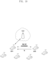
- FIG. 10 is a diagram illustrating a scenario of performing inter-UE coordination according to an embodiment of the disclosure.
- the inter-UE coordination may refer to providing an improved sidelink service by sharing helpful information between UEs.
- information shared for inter-UE coordination is not limited to specific information.
- the disclosure focuses on resource allocation related information.
- the UE that performs transmission in the sidelink may allocate a resource through a direct sensing and resource selection procedure (Mode2), or when the UE performing transmission is within the coverage of the base station (BS), the base station may allocate a resource (Model).
- a method in which the UE receives resource allocation and resource allocation related information from another UE through inter-UE coordination may be additionally considered.
- the power consumption of the UE can be minimized when another UE performs resource allocation instead.
- a lot of power may be consumed for the UE to perform sensing to select a sidelink transmission resource. Therefore, in consideration of this advantage, a method of receiving resource allocation related information from another UE through inter-UE coordination may be considered.
- the operation of continuously receiving resource allocation information from another UE may also cause power consumption of the UE. Therefore, through DRX operation and a wake-up signal (WUS), a method in which the UE receives resource allocation related information from another UE may be used.
- WUS wake-up signal
- FIG. 10 shows a case in which UE-B receives resource allocation information from UE-A through inter-UE coordination.
- time and frequency resource allocation information provided by UE-A to UE-B is called resource selection assistance information (RSAI).
- RSAI resource selection assistance information
- FIG. 10 illustrates a case in which UE-A indicates the RSAI to UE-B and UE-B performs transmission to UE-A, the disclosure is not limited thereto. That is, using the RSAI provided by UE-A, UE-B may perform transmission to a UE other than UE-A.
- UE-B may receive the RSAI from a UE other than UE-A or from one or more UEs.
- the disclosure proposes a condition for the UE to transmit the RSAI and methods for DRX operation and WUS transmission. First, the following methods may be considered as the condition for the UE to transmit the RSAI. Note that the disclosure is not limited to only the following methods as the transmission condition of RSAI. It is also noted that a combination of the following methods may be used.
- a UE capable of transmitting RSAI performs RSAI transmission when receiving an RSAI request from another UE.
- UE-B may request the RSAI from UE-A.
- the RSAI request may be made through SCI or through PC5 MAC-CE or PC5 RRC between UEs.
- the UE may request the RSAI and then operate in DRX on-duration to receive the RSAI from another UE.
- a method in which the UE operates in DRX on-duration immediately after requesting the RSAI may be used, or a method in which the UE requests the RSAI, then a timer operates, and the UE operates in on-duration after the expiration of the timer may be used.
- the UE performs RSAI transmission when receiving an RSAI transmission request to another UE from the base station.
- the base station may request UE-A to perform RSAI transmission to another UE.
- the RSAI request may be made through DCI, or may be made through Uu MAC-CE or Uu RRC between the base station and the UE.
- a UE transmitting the RSAI may transmit a WUS to wake up a UE receiving the RSAI in consideration of the case where the receiving UE operates in DRX off-duration.
- the RSAI may be the WUS, or a method of transmitting the RSAI after WUS transmission may be used.
- a UE capable of transmitting RSAI performs RSAI transmission to another UE.
- FIG. 10 when reception in a resource selected by UE-B is not successful in UE-A, it may be interpreted as an operation in which UE-A selects an appropriate resource and indicates it to UE-B.
- the RSAI may be information on retransmission resources or information on new resource transmission.
- the UE may expect to receive the RSAI after transmitting the NACK X times.
- a method in which the UE transmits the NACK X times and then immediately operates in DRX on-duration may be used, or a method in which the UE transmits the NACK X times, then a timer operates, and the UE operates in on-duration after the expiration of the timer may be used.
- RSAI information is a retransmission resource
- retransmission may be performed at a corresponding resource location
- new transmission may be performed at a corresponding resource location.
- a UE capable of transmitting RSAI performs RSAI transmission in accordance with the UE's decision.
- a UE transmitting the RSAI may transmit a WUS to wake a UE receiving the RSAI in consideration of the case where the receiving UE operates in DRX off-duration.
- the RSAI may be the WUS, or a method of transmitting the RSAI after WUS transmission may be used. If the UE capable of transmitting RSAI wants to periodically perform RSAI transmission, the following method may be used.
- a periodic RSAI transmission cycle may be configured and shared between UEs.
- a periodic WUS transmission cycle is configured and shared between UEs, and the UE for transmitting the RSAI may transmit the RSAI after the WUS transmission.
- the corresponding transmission may be performed through SCI or through PC5 MAC-CE or PC5 RRC between UEs.
- SCI transmission a method in which corresponding information is included and indicated in the 1 st SCI may be considered.
- the 1 st SCI may be a new SCI format differentiated from the SCI format 1-A.
- a method in which corresponding information is included and indicated in the 2 nd SCI may be considered.
- the 2 nd SCI may be a new SCI format differentiated from the SCI format 2-A or SCI format 2-B.
- the UE capable of transmitting RSAI may provide aperiodic resource allocation information to another UE and may provide periodic resource allocation information to another UE. If periodic RSAI is provided, reservation interval information for RSAI may be included as RSAI information and transmitted. In this case, for the periodic RSAI, a resource may be periodically reserved at a time location (the frequency location is the same) indicated by a reservation interval in a time and frequency location of a resource of the RSAI determined for one transport block (TB).
- TB transport block
- FIGS. 11 and 12 A transmitter, a receiver, and a processor of the UE and the base station for performing the above embodiments of the disclosure are illustrated in FIGS. 11 and 12 .
- a method for the UE to perform sensing and resource selection in the sidelink is shown, and to perform this, the receiver, the processor, and the transmitter of the base station and the UE should operate according to the embodiments.
- FIG. 11 is a block diagram illustrating the structure of a UE according to an embodiment of the disclosure.
- the UE of the disclosure may include a UE receiver 1100, a UE transmitter 1104, and a UE processor 1102.
- the UE receiver 1100 and the UE transmitter 1104 may be collectively referred to as a transceiver in embodiments of the disclosure.
- the transceiver may transmit/receive a signal to/from the base station. This signal may include control information and data.
- the transceiver may include an RF transmitter for up-converting and amplifying a frequency of a signal to be transmitted, and an RF receiver for low-noise amplifying and down-converting a received signal.
- the transceiver may receive a signal through a wireless channel and output it to the UE processor 1102, and transmit a signal outputted from the UE processor 1102 through a wireless channel.
- the UE processor 1102 may control a series of processes such that the UE can operate according to the above-described embodiments of the disclosure.
- FIG. 12 is a block diagram illustrating the structure of a base station according to an embodiment of the disclosure.
- the base station of the disclosure may include a base station receiver 1201, a base station transmitter 1205, and a base station processor 1203.
- the base station receiver 1201 and the base station transmitter 1205 may be collectively referred to as a transceiver in embodiments of the disclosure.
- the transceiver may transmit/receive a signal to/from the UE. This signal may include control information and data.
- the transceiver may include an RF transmitter for up-converting and amplifying a frequency of a signal to be transmitted, and an RF receiver for low-noise amplifying and down-converting a received signal.
- the transceiver may receive a signal through a wireless channel and output it to the base station processor 1203, and transmit a signal outputted from the base station processor 1203 through a wireless channel.
- the base station processor 1203 may control a series of processes such that the base station can operate according to the above-described embodiments of the disclosure.
Landscapes
- Engineering & Computer Science (AREA)
- Computer Networks & Wireless Communication (AREA)
- Signal Processing (AREA)
- Mobile Radio Communication Systems (AREA)
Applications Claiming Priority (2)
| Application Number | Priority Date | Filing Date | Title |
|---|---|---|---|
| KR1020200090360A KR20220011444A (ko) | 2020-07-21 | 2020-07-21 | 무선 통신 시스템에서 사이드링크의 비연속적 수신을 지원하기 위한 방법 및 장치 |
| PCT/KR2021/009342 WO2022019615A1 (ko) | 2020-07-21 | 2021-07-20 | 무선 통신 시스템에서 사이드링크의 비연속적 수신을 지원하기 위한 방법 및 장치 |
Publications (3)
| Publication Number | Publication Date |
|---|---|
| EP4142425A1 true EP4142425A1 (de) | 2023-03-01 |
| EP4142425A4 EP4142425A4 (de) | 2023-10-25 |
| EP4142425B1 EP4142425B1 (de) | 2026-03-04 |
Family
ID=79729612
Family Applications (1)
| Application Number | Title | Priority Date | Filing Date |
|---|---|---|---|
| EP21845784.4A Active EP4142425B1 (de) | 2020-07-21 | 2021-07-20 | Verfahren und vorrichtung zur unterstützung des diskontinuierlichen empfangs von sidelink in einem drahtloskommunikationssystem |
Country Status (5)
| Country | Link |
|---|---|
| US (1) | US20230180342A1 (de) |
| EP (1) | EP4142425B1 (de) |
| KR (1) | KR20220011444A (de) |
| CN (1) | CN115699988A (de) |
| WO (1) | WO2022019615A1 (de) |
Cited By (4)
| Publication number | Priority date | Publication date | Assignee | Title |
|---|---|---|---|---|
| US20220360389A1 (en) * | 2019-06-25 | 2022-11-10 | Sharp Kabushiki Kaisha | Method performed by user equipment, and user equipment |
| WO2023154409A1 (en) * | 2022-02-11 | 2023-08-17 | Ofinno, Llc | Sidelink transmission based on active time |
| EP4216651A4 (de) * | 2020-10-15 | 2023-11-15 | Guangdong Oppo Mobile Telecommunications Corp., Ltd. | Sidelink-übertragungsverfahren und endgerät |
| EP4461087A4 (de) * | 2022-02-13 | 2025-02-19 | Apple Inc. | Systeme, verfahren und vorrichtungen zur mac-schicht-inter-ue-koordination (iuc) |
Families Citing this family (9)
| Publication number | Priority date | Publication date | Assignee | Title |
|---|---|---|---|---|
| US12114289B2 (en) * | 2020-08-07 | 2024-10-08 | Qualcomm Incorporated | Coordination signaling for sidelink resource selection |
| US20230232427A1 (en) * | 2020-08-13 | 2023-07-20 | Qualcomm Incorporated | Techniques for sub-band precoding in sidelink communications |
| KR20230092903A (ko) * | 2020-10-22 | 2023-06-26 | 엘지전자 주식회사 | Nr v2x에서 drx 온-듀레이션의 오정렬로 인한 패킷 상실을 해결하는 방법 및 장치 |
| EP4305920A1 (de) * | 2021-03-11 | 2024-01-17 | InterDigital Patent Holdings, Inc. | Verfahren, architekturen, vorrichtungen und systeme zur durchführung eines diskontinuierlichen empfangs auf sidelink |
| WO2022191647A1 (en) | 2021-03-12 | 2022-09-15 | Samsung Electronics Co., Ltd. | Method and device for supporting sidelink discontinuous reception in wireless communication system |
| WO2022265419A1 (ko) * | 2021-06-18 | 2022-12-22 | 엘지전자 주식회사 | Nr v2x에서 그룹캐스트 데스티네이션 l2 id를 기반으로 sl drx 타이머를 동작시키는 방법 및 장치 |
| WO2023132931A1 (en) * | 2022-01-07 | 2023-07-13 | Apple Inc. | Technologies for inter-user equipment coordination |
| KR102815019B1 (ko) | 2022-08-17 | 2025-05-30 | 엘지전자 주식회사 | 무선통신시스템에서 디스커버리 리소스 풀에 관련된 ue의 동작 방법 |
| WO2025034323A1 (en) * | 2023-08-07 | 2025-02-13 | Interdigital Patent Holdings, Inc. | Sidelink tx ue operation over multiple carriers |
Family Cites Families (16)
| Publication number | Priority date | Publication date | Assignee | Title |
|---|---|---|---|---|
| US9949145B2 (en) * | 2013-09-15 | 2018-04-17 | Lg Electronics Inc. | Discontinuous reception supporting method in wireless communication system supporting change of usage of radio resource and apparatus therefor |
| EP3697158B1 (de) * | 2014-03-30 | 2021-12-08 | LG Electronics Inc. | Verfahren zum senden/empfangen von downlink-steuerinformationen in einem drahtloskommunikationssystem mit unterstützung von vorrichtung-zu-vorrichtung-kommunikation und einrichtung dafür |
| US20240357702A1 (en) * | 2015-09-30 | 2024-10-24 | Lg Electronics Inc. | Method and apparatus for carrying out wireless communication related to mac reset in nr v2x |
| WO2018064477A1 (en) * | 2016-09-30 | 2018-04-05 | Intel IP Corporation | Systems and methods for discontinuous reception in device-to-device communication |
| US10362626B2 (en) * | 2016-10-17 | 2019-07-23 | Asustek Computer Inc. | Method and apparatus for handling DRX (discontinuous reception) operation in a wireless communication system |
| EP3609259A4 (de) * | 2017-05-11 | 2020-04-01 | LG Electronics Inc. -1- | Verfahren und vorrichtung zur zuweisung einer sidelink-ressource unter verwendung eines relaisbenutzergeräts in einem drahtloskommunikationssystem |
| US10893571B2 (en) * | 2017-11-17 | 2021-01-12 | Qualcomm Incorporated | Radio link monitoring based on discontinuous reception mode |
| EP3654719A1 (de) * | 2018-11-14 | 2020-05-20 | Samsung Electronics Co., Ltd. | Verfahren und vorrichtung zur konfiguration von parametern in einem vehicle-to-everything-system |
| KR102852257B1 (ko) * | 2019-02-14 | 2025-08-29 | 주식회사 아이티엘 | 무선통신 시스템에서 harq 재전송을 지원하는 방법 및 장치 |
| CN113382379B (zh) * | 2020-03-10 | 2024-06-04 | 华为技术有限公司 | 无线通信方法和通信装置 |
| CN113382380A (zh) * | 2020-03-10 | 2021-09-10 | 华为技术有限公司 | 一种侧行链路的通信方法和通信装置 |
| US11758481B2 (en) * | 2020-03-26 | 2023-09-12 | Qualcomm Incorporated | Independent sidelink (SL) discontinuous reception (DRX) |
| CN113543235B (zh) * | 2020-04-14 | 2024-11-19 | 华为技术有限公司 | Drx模式的确定方法及通信装置 |
| CN115552981A (zh) * | 2020-05-14 | 2022-12-30 | Lg电子株式会社 | 用于在nr v2x中接收副链路重新发送分组的方法和装置 |
| WO2021263106A2 (en) * | 2020-06-26 | 2021-12-30 | Ofinno, Llc | Discontinuous reception |
| WO2022015015A1 (en) * | 2020-07-13 | 2022-01-20 | Lg Electronics Inc. | Sidelink drx operation based on resource allocation |
-
2020
- 2020-07-21 KR KR1020200090360A patent/KR20220011444A/ko active Pending
-
2021
- 2021-07-20 US US17/999,745 patent/US20230180342A1/en active Pending
- 2021-07-20 WO PCT/KR2021/009342 patent/WO2022019615A1/ko not_active Ceased
- 2021-07-20 EP EP21845784.4A patent/EP4142425B1/de active Active
- 2021-07-20 CN CN202180038175.XA patent/CN115699988A/zh active Pending
Cited By (7)
| Publication number | Priority date | Publication date | Assignee | Title |
|---|---|---|---|---|
| US20220360389A1 (en) * | 2019-06-25 | 2022-11-10 | Sharp Kabushiki Kaisha | Method performed by user equipment, and user equipment |
| US12149468B2 (en) * | 2019-06-25 | 2024-11-19 | Sharp Kabushiki Kaisha | Method performed by user equipment, and user equipment |
| EP4216651A4 (de) * | 2020-10-15 | 2023-11-15 | Guangdong Oppo Mobile Telecommunications Corp., Ltd. | Sidelink-übertragungsverfahren und endgerät |
| US12557171B2 (en) | 2020-10-15 | 2026-02-17 | Guangdong Oppo Mobile Telecommunications Corp., Ltd. | Sidelink transmission method and terminal |
| US12557170B2 (en) | 2020-10-15 | 2026-02-17 | Guangdong Oppo Mobile Telecommunications Corp., Ltd. | Sidelink transmission method and terminal |
| WO2023154409A1 (en) * | 2022-02-11 | 2023-08-17 | Ofinno, Llc | Sidelink transmission based on active time |
| EP4461087A4 (de) * | 2022-02-13 | 2025-02-19 | Apple Inc. | Systeme, verfahren und vorrichtungen zur mac-schicht-inter-ue-koordination (iuc) |
Also Published As
| Publication number | Publication date |
|---|---|
| WO2022019615A1 (ko) | 2022-01-27 |
| KR20220011444A (ko) | 2022-01-28 |
| US20230180342A1 (en) | 2023-06-08 |
| CN115699988A (zh) | 2023-02-03 |
| EP4142425A4 (de) | 2023-10-25 |
| EP4142425B1 (de) | 2026-03-04 |
Similar Documents
| Publication | Publication Date | Title |
|---|---|---|
| EP4142425B1 (de) | Verfahren und vorrichtung zur unterstützung des diskontinuierlichen empfangs von sidelink in einem drahtloskommunikationssystem | |
| JP7783185B2 (ja) | V2xシステムで端末の間の協力を通じるリソース割り当て方法及び装置 | |
| EP3893563B1 (de) | Verfahren und vorrichtung zur zuweisung von übertragungsleistung in einem drahtloskommunikationssystem | |
| US12047985B2 (en) | Method and device for supporting sidelink discontinuous reception in wireless communication system | |
| US20220201528A1 (en) | Method and device for measuring and reporting channel state in sidelink communication | |
| EP4304275A1 (de) | Verfahren und vorrichtung zur ressourcenzuweisung in einem drahtloskommunikationssystem durch sidelink-inter-ue-koordination | |
| US12356435B2 (en) | Method and apparatus for resource allocation by sidelink inter-UE coordination in communication system | |
| US11523300B2 (en) | Method and apparatus for configuring sidelink data bearer in wireless communication system | |
| EP4135436A1 (de) | Verfahren und vorrichtung zur ressourcenzuweisung durch trägeraggregation in einem v2x-system | |
| US20230276526A1 (en) | Method and device for supporting sidelink discontinuous reception in wireless communication system | |
| KR102906240B1 (ko) | 무선 통신 시스템에서 사이드링크 다중 안테나 전송을 지원하기 위한 방법 및 장치 | |
| EP4373189A1 (de) | Verfahren und vorrichtung zur inter-ue-koordination von sidelink in einem drahtloskommunikationssystem | |
| KR20210153976A (ko) | V2x 시스템에서 단말 간 협력을 통한 자원 할당 방법 및 장치 | |
| KR20210145562A (ko) | V2x 시스템에서 단말 간 협력을 통한 자원 할당 방법 및 장치 | |
| KR20220136799A (ko) | 무선 통신 시스템에서 사이드링크의 비연속적 수신을 지원하기 위한 방법 및 장치 | |
| KR20200112569A (ko) | 무선 통신 시스템에서 사이드링크 데이터 전송을 수행하는 방법 및 장치 | |
| JP7769132B2 (ja) | V2xシステムでリソースを割り当てる方法及び装置 | |
| KR20230108187A (ko) | V2x 시스템에서 자원을 할당하는 방법 및 장치 | |
| KR20220128232A (ko) | 무선 통신 시스템에서 사이드링크의 비연속적 수신을 지원하기 위한 방법 및 장치 | |
| CN116998200A (zh) | 无线通信系统中支持侧链路不连续接收的方法和设备 | |
| CN118525589A (zh) | 用于v2x系统中的资源分配的方法和装置 | |
| CN117796104A (zh) | 无线通信系统中用于侧链路的ue间协调的方法和装置 | |
| CN117280813A (zh) | 无线通信系统中通过侧链路ue间协调进行资源分配的方法和设备 | |
| KR20220148693A (ko) | 무선 통신 시스템에서 사이드링크의 단말 간 협력을 통한 자원 할당 방법 및 장치 | |
| KR20220126608A (ko) | 무선 통신 시스템에서 사이드링크의 자원 할당 방법 및 장치 |
Legal Events
| Date | Code | Title | Description |
|---|---|---|---|
| STAA | Information on the status of an ep patent application or granted ep patent |
Free format text: STATUS: THE INTERNATIONAL PUBLICATION HAS BEEN MADE |
|
| PUAI | Public reference made under article 153(3) epc to a published international application that has entered the european phase |
Free format text: ORIGINAL CODE: 0009012 |
|
| STAA | Information on the status of an ep patent application or granted ep patent |
Free format text: STATUS: REQUEST FOR EXAMINATION WAS MADE |
|
| 17P | Request for examination filed |
Effective date: 20221123 |
|
| AK | Designated contracting states |
Kind code of ref document: A1 Designated state(s): AL AT BE BG CH CY CZ DE DK EE ES FI FR GB GR HR HU IE IS IT LI LT LU LV MC MK MT NL NO PL PT RO RS SE SI SK SM TR |
|
| A4 | Supplementary search report drawn up and despatched |
Effective date: 20230926 |
|
| DAV | Request for validation of the european patent (deleted) | ||
| DAX | Request for extension of the european patent (deleted) | ||
| RIC1 | Information provided on ipc code assigned before grant |
Ipc: H04W 72/25 20230101ALI20230920BHEP Ipc: H04L 1/1829 20230101ALI20230920BHEP Ipc: H04W 4/70 20180101ALI20230920BHEP Ipc: H04W 92/18 20090101ALI20230920BHEP Ipc: H04W 4/40 20180101ALI20230920BHEP Ipc: H04W 72/02 20090101ALI20230920BHEP Ipc: H04W 76/14 20180101ALI20230920BHEP Ipc: H04W 76/28 20180101AFI20230920BHEP |
|
| RIC1 | Information provided on ipc code assigned before grant |
Ipc: H04W 76/28 20180101AFI20250811BHEP Ipc: H04W 76/14 20180101ALI20250811BHEP Ipc: H04W 72/02 20090101ALI20250811BHEP Ipc: H04W 4/40 20180101ALI20250811BHEP Ipc: H04W 92/18 20090101ALI20250811BHEP Ipc: H04W 4/70 20180101ALI20250811BHEP Ipc: H04L 1/1829 20230101ALI20250811BHEP Ipc: H04W 72/25 20230101ALI20250811BHEP |
|
| GRAP | Despatch of communication of intention to grant a patent |
Free format text: ORIGINAL CODE: EPIDOSNIGR1 |
|
| STAA | Information on the status of an ep patent application or granted ep patent |
Free format text: STATUS: GRANT OF PATENT IS INTENDED |
|
| INTG | Intention to grant announced |
Effective date: 20250925 |
|
| GRAS | Grant fee paid |
Free format text: ORIGINAL CODE: EPIDOSNIGR3 |
|
| GRAA | (expected) grant |
Free format text: ORIGINAL CODE: 0009210 |
|
| STAA | Information on the status of an ep patent application or granted ep patent |
Free format text: STATUS: THE PATENT HAS BEEN GRANTED |
|
| AK | Designated contracting states |
Kind code of ref document: B1 Designated state(s): AL AT BE BG CH CY CZ DE DK EE ES FI FR GB GR HR HU IE IS IT LI LT LU LV MC MK MT NL NO PL PT RO RS SE SI SK SM TR |
|
| REG | Reference to a national code |
Ref country code: CH Ref legal event code: F10 Free format text: ST27 STATUS EVENT CODE: U-0-0-F10-F00 (AS PROVIDED BY THE NATIONAL OFFICE) Effective date: 20260304 Ref country code: GB Ref legal event code: FG4D |
|
| REG | Reference to a national code |
Ref country code: DE Ref legal event code: R096 Ref document number: 602021049424 Country of ref document: DE |