EP4142186B1 - Verteiltes antennensystem und kommunikationssystem - Google Patents
Verteiltes antennensystem und kommunikationssystem Download PDFInfo
- Publication number
- EP4142186B1 EP4142186B1 EP22170871.2A EP22170871A EP4142186B1 EP 4142186 B1 EP4142186 B1 EP 4142186B1 EP 22170871 A EP22170871 A EP 22170871A EP 4142186 B1 EP4142186 B1 EP 4142186B1
- Authority
- EP
- European Patent Office
- Prior art keywords
- digital
- analog
- unit
- downlink
- signal
- Prior art date
- Legal status (The legal status is an assumption and is not a legal conclusion. Google has not performed a legal analysis and makes no representation as to the accuracy of the status listed.)
- Active
Links
Images




Classifications
-
- H—ELECTRICITY
- H04—ELECTRIC COMMUNICATION TECHNIQUE
- H04B—TRANSMISSION
- H04B10/00—Transmission systems employing electromagnetic waves other than radio-waves, e.g. infrared, visible or ultraviolet light, or employing corpuscular radiation, e.g. quantum communication
- H04B10/25—Arrangements specific to fibre transmission
- H04B10/2575—Radio-over-fibre, e.g. radio frequency signal modulated onto an optical carrier
- H04B10/25752—Optical arrangements for wireless networks
- H04B10/25753—Distribution optical network, e.g. between a base station and a plurality of remote units
-
- H—ELECTRICITY
- H04—ELECTRIC COMMUNICATION TECHNIQUE
- H04B—TRANSMISSION
- H04B10/00—Transmission systems employing electromagnetic waves other than radio-waves, e.g. infrared, visible or ultraviolet light, or employing corpuscular radiation, e.g. quantum communication
- H04B10/25—Arrangements specific to fibre transmission
- H04B10/2575—Radio-over-fibre, e.g. radio frequency signal modulated onto an optical carrier
- H04B10/25752—Optical arrangements for wireless networks
- H04B10/25758—Optical arrangements for wireless networks between a central unit and a single remote unit by means of an optical fibre
- H04B10/25759—Details of the reception of RF signal or the optical conversion before the optical fibre
-
- H—ELECTRICITY
- H04—ELECTRIC COMMUNICATION TECHNIQUE
- H04B—TRANSMISSION
- H04B7/00—Radio transmission systems, i.e. using radiation field
- H04B7/02—Diversity systems; Multi-antenna system, i.e. transmission or reception using multiple antennas
- H04B7/022—Site diversity; Macro-diversity
-
- H—ELECTRICITY
- H04—ELECTRIC COMMUNICATION TECHNIQUE
- H04B—TRANSMISSION
- H04B2210/00—Indexing scheme relating to optical transmission systems
- H04B2210/006—Devices for generating or processing an RF signal by optical means
Definitions
- Embodiments of the present disclosure generally relate to the field of communications, and specifically to a distributed antenna system and communication system.
- Embodiments of the present disclosure provide a distributed antenna system and a communication system, which can achieve large-bandwidth data transmission.
- a distributed antenna system comprises: a first access unit and a remote unit, wherein the first access unit and the remote unit are coupled to each other via an analog optical fiber, and the first access unit comprises: a first port configured to receive a first downlink analog radio frequency signal from a first base station; a first analog-to-digital conversion unit coupled to the first port and configured to perform analog-to-digital conversion on the first downlink analog radio frequency signal to generate a first downlink digital signal; a first digital processing unit coupled to the first analog-to-digital conversion unit and configured to perform digital signal processing on the first downlink digital signal to generate a second downlink digital signal; a first digital-to-analog conversion unit coupled to the first digital processing unit and configured to perform digital-to-analog conversion on the second downlink digital signal to generate a second downlink analog radio frequency signal; and an analog optical module coupled to the first digital-to-analog conversion unit and configured to perform electro-optical conversion on the
- the analog optical module is further configured to receive an uplink analog optical signal from the remote unit, and convert the uplink analog optical signal into a first uplink analog radio frequency signal
- the first access unit further comprises: a second analog-to-digital conversion unit coupled to the analog optical module and configured to perform analog-to-digital conversion on the first uplink analog radio frequency signal to generate a first uplink digital signal
- the first digital processing unit is further coupled to the second analog-to-digital conversion unit and configured to perform digital signal processing on the first uplink digital signal to generate a second uplink digital signal
- a second digital-to-analog conversion unit coupled to the first digital processing unit and the first port and configured to perform digital-to-analog conversion on the second uplink digital signal to generate a second uplink analog radio frequency signal which is transmitted to the first base station via the first port.
- the first access unit further comprises a first digital optical module coupled to the first digital processing unit
- the distributed antenna system further comprises a second access unit
- the second access unit comprises: a second port configured to receive a third downlink analog radio frequency signal from the second base station; a third analog-to-digital conversion unit coupled to the second port and configured to perform analog-digital conversion on the third downlink analog radio frequency signal to generate a third downlink digital signal; a second digital processing unit coupled to the third analog-to-digital conversion unit and configured to perform digital signal processing on the third downlink digital signal to generate a fourth downlink digital signal; a second digital optical module coupled to the second digital processing unit and coupled to the first digital optical module via a digital optical fiber and configured to perform electro-optical conversion on the fourth downlink digital signal to generate a downlink digital optical signal which is transmitted to the first digital optical module via the digital optical fiber.
- the first digital optical module is configured to perform photoelectric conversion on the downlink digital optical signal to generate a fifth downlink digital signal; the first digital processing unit is further configured to perform digital signal processing on the first downlink digital signal and the fifth downlink digital signal to generate a second downlink digital signal.
- the first digital optical module is further configured to perform electro-optical conversion on the second uplink digital signal to generate an uplink digital optical signal
- the second digital optical module is further configured to perform photoelectric conversion on the uplink digital optical signal to generate a third uplink digital signal
- the second digital processing unit is further configured to perform digital signal processing on the third uplink digital signal to generate a fourth uplink digital signal
- the second access unit further comprises: a third digital-to-analog conversion unit coupled to the second digital processing unit and configured to perform digital-to-analog conversion on the fourth uplink digital signal to generate a third uplink analog radio frequency signal which is transmitted to the second base station via the second port.
- the distributed antenna system further comprises a network extension unit coupled between the first access unit and the plurality of remote units via the analog optical fiber.
- the first access unit further comprises: a combining unit coupled between the plurality of first digital-to-analog conversion units and the analog optical modules and configured to combine the plurality of second downlink analog radio frequency signals to generate a combined downlink analog radio frequency signal; and the analog optical module further configured to perform electro-optical conversion on the combined downlink analog radio frequency signal to generate a first downlink analog optical signal which is transmitted to the remote unit via the analog optical fiber.
- the first access unit further comprises: a splitting unit coupled to the plurality of second analog-to-digital conversion units and the analog optical module and configured to split the first uplink analog radio frequency signal to generate a plurality of split uplink analog radio frequency signals; and the plurality of second analog-to-digital conversion units are configured to perform analog-to-digital conversion on the plurality of split uplink analog radio frequency signals to generate a plurality of first uplink digital signals.
- the distributed antenna system further comprises: a plurality of splitting and combining units, each of the plurality of splitting and combining units is coupled between the plurality of first base stations and the corresponding first ports, each splitting and combining unit is configured to combine a plurality of downlink analog radio frequency signals having the same frequency band from the plurality of first base stations to generate a first downlink analog radio frequency signal to output to a corresponding first port, and each splitting and combining unit is further configured to split the second uplink analog radio frequency signal from the corresponding first port to output to the plurality of first base stations.
- the plurality of first downlink analog radio frequency signals have at least one of the following: one or more network standards, one or more network frequency bands, and one or more service types.
- the first digital processing unit is further configured to perform at least one of digital filtering and digital power balancing performed on the first downlink digital signal to generate the second downlink digital signal.
- a communication system comprising: one or more base stations; and the distributed antenna system according to the first aspect, the distributed antenna system coupled to one or more base stations.
- the access unit performs analog-to-digital conversion, digital processing, digital-to-analog conversion, and electro-optical conversion on the analog radio frequency signal, and then transmits it to the remote, which can achieve large-bandwidth data transmission.
- the term “comprises” and its variants are to be read as open-ended terms that mean “comprises, but is not limited to.”
- the term “or” is to be read as “and/or” unless the context clearly indicates otherwise.
- the term “based on” is to be read as “based at least in part on.”
- the term “one example implementation” and “an example implementation” are to be read as “at least one example implementation.”
- the term “another implementation” is to be read as “at least one other implementation.” Terms “a first”, “a second” and others can denote different or identical objects. The following text may also contain other explicit or implicit definitions.
- the traditional distributed antenna system based on digital optical fibers is confronted with the problem of large-bandwidth data transmission, and the hardware cost of remote transmission increases sharply.
- the traditional distributed antenna system is also confronted with the problem of multi-operator and multi-service access such as compatibility with 2G, 3G, 4G and 5G.
- the loss in the transmission of signals at different frequencies varies greatly. It is difficult for the traditional distributed antenna system cannot to meet the requirements of simultaneous access to multiple wireless communication networks, such as interference between multi-base station and multi-standard signals, and power balance between multi-base station and multi-standard signals.
- the distributed antenna system comprises: a first access unit and a remote unit, the first access unit and the remote unit coupled to each other via an analog optical fiber, the first access unit comprising: a first port configured to receive a first downlink analog radio frequency signal from a first base station; a first analog-to-digital conversion unit coupled to the first port and configured to perform analog-to-digital conversion on the first downlink analog radio frequency signal to generate a first downlink digital signal; a first digital processing unit coupled to the first analog-to-digital conversion unit and configured to perform digital signal processing on the first downlink digital signal to generate a second downlink digital signal; a first digital-to-analog conversion unit coupled to the first digital processing unit and configured to perform digital-to-analog conversion on the second downlink digital signal to generate a second downlink analog radio frequency signal; and an analog optical module coupled to the first digital-to-analog
- the access unit performs analog-to-digital conversion, digital processing, digital-to-analog conversion, and electro-optical conversion on the analog radio frequency signal, and then transmits the converted signal to the remote unit through the analog optical fiber, which can realize large-bandwidth data transmission.
- FIG. 1 is a schematic diagram of a distributed antenna system 100 according to a first embodiment of the present disclosure.
- the distributed antenna system 100 comprises a first access unit 110 and a remote unit 120.
- the first access unit 110 and the remote unit 120 are coupled via an analog optical fiber 130.
- the first access unit 110 includes a first port 111, a first analog-to-digital conversion unit 112, a first digital processing unit 113, a first digital-to-analog conversion unit 114 and an analog optical module 115.
- the first port 111 is used to receive a first downlink analog radio frequency signal from a first base station (not shown).
- the first analog-to-digital conversion unit 112 is coupled to the first port 111.
- the first analog-to-digital conversion unit 112 is configured to perform analog-to-digital conversion on the first downlink analog radio frequency signal to generate a first downlink digital signal.
- the first digital processing unit 113 is coupled to the first analog-to-digital conversion unit 112.
- the first digital processing unit 113 is configured to perform digital signal processing on the first downlink digital signal to generate a second downlink digital signal.
- the first digital processing unit can be implemented by for example a Field Programmable Gate Array FPGA, a Digital Signal Processor DSP, etc.
- the digital signal processing for example may include, but is not limited to, digital filtering, digital power balancing, TDD synchronization tracking, and digital power statistics.
- the first digital-to-analog conversion unit 114 is coupled to the first digital processing unit 113.
- the first digital-to-analog conversion unit 114 is configured to perform digital-to-analog conversion on the second downlink digital signal to generate a second downlink analog radio frequency signal.
- the analog optical module 115 is coupled to the first digital-to-analog conversion unit 114.
- the analog optical module 115 is configured to perform electro-optical conversion on the second downlink analog radio frequency signal to generate a first downlink analog optical signal which is transmitted to the remote unit 120 via the analog optical fiber 130.
- the remote unit 120 may be configured to perform photoelectric conversion on the first downlink analog optical signal to generate a downlink analog radio frequency signal for transmission.
- the remote unit 120 may include an analog optical module for performing photoelectric conversion on the first downlink analog optical signal to generate a downlink analog radio frequency signal.
- the remote unit 120 may be coupled to an antenna to transmit the downlink analog radio frequency signal via the antenna.
- the access unit performs analog-to-digital conversion, digital processing, digital-to-analog conversion, and electro-optical conversion on the downlink analog radio frequency signal, and then transmits the converted signal to the remote unit through the analog optical fiber, so that the large-bandwidth data transmission of the downlink signal is achieved through the analog optical fiber.
- using the analog optical fiber for remote transmission may facilitate sharing and co-construction to save the transmission cost.
- the remote unit 120 may receive an uplink analog radio frequency signal via an antenna, and perform electro-optical conversion on the uplink analog radio frequency signal to generate an uplink analog optical signal.
- the analog optical module 115 may be configured to receive the uplink analog optical signal from the remote unit 120 and convert the uplink analog optical signal into a first uplink analog radio frequency signal.
- the first access unit 110 further includes a second analog-to-digital conversion unit 116 and a second digital-to-analog conversion unit 117.
- the second analog-to-digital conversion unit 116 is coupled to the analog optical module 115.
- the second analog-to-digital conversion unit 116 is configured to perform analog-to-digital conversion on the first uplink analog radio frequency signal to generate a first uplink digital signal.
- the first digital processing unit 113 is coupled to the second analog-to-digital conversion unit 116.
- the first digital processing unit 113 is configured to perform digital signal processing on the first uplink digital signal to generate a second uplink digital signal.
- the second digital-to-analog conversion unit 117 is coupled to the first digital processing unit 113 and the first port 111.
- the second digital-to-analog conversion unit 117 may be configured to perform digital-to-analog conversion on the second uplink digital signal to generate a second uplink analog radio frequency signal which will be transmitted to the first base station via the first port 111.
- the first analog-to-digital conversion unit 112 and the second digital-to-analog conversion unit 117 are coupled to the first port 111 via a duplexer (not shown).
- the duplexer is used to receive the second uplink analog radio frequency signal from the second digital-to-analog conversion unit 117 and transmit it to the first port 111.
- the duplexer is further configured to receive the first downlink analog radio frequency signal from the first port 111 and transmit the first downlink analog radio frequency signal to the first analog-to-digital conversion unit 112.
- the first analog-to-digital conversion unit 112 and the second digital-to-analog conversion unit 117 are coupled to the first port 111 via a radio frequency switch circuit (not shown).
- the radio frequency switch circuit Upon receiving the second uplink analog radio frequency signal, the radio frequency switch circuit is configured to connect the first port 111 with the second digital-to-analog conversion unit 117, to transmit the second uplink analog radio frequency signal from the second digital-to-analog conversion unit 117 to the first port 111.
- the radio frequency switch circuit is further configured to connect the first port 111 with the first analog-to-digital conversion unit 112 upon sending the first downlink analog radio frequency signal, to transmit the first downlink analog radio frequency signal from the first port 111 to the first analog-to-digital conversion unit 112.
- first analog-to-digital conversion unit and the second digital-to-analog conversion unit are shown as separate units, this is only an example, and the first analog-to-digital conversion unit and the second digital-to-analog conversion unit can also be integrated as a first analog-to-digital/digital-to-analog conversion unit.
- second analog-to-digital conversion unit and the second digital-to-analog conversion unit are shown as separate units herein, this is only an example, and the second analog-to-digital conversion unit and the second digital-to-analog conversion unit may be integrated as a second analog-to-digital/digital-to-analog conversion unit.
- the access unit performs photoelectric conversion, analog-to-digital conversion, digital processing, and digital-to-analog conversion on the uplink analog optical signal received from the remote unit via the analog optical fiber, and then transmits it to the base station, so that large-bandwidth data transmission of the uplink signal can be realized through the analog optical fiber.
- the distributed antenna system 100 may further include a network extension unit 140 coupled between the first access unit 110 and the remote unit 120.
- the network extension unit 140 may be coupled to the first access unit 110 and the remote unit 120 through the analog optical fiber.
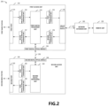
- FIG. 2 is a schematic diagram of a distributed antenna system 200 according to a second embodiment of the present disclosure.
- a distributed antenna system 200 comprises a first access unit 210, a remote unit 220 and a second access unit 240.
- the first access unit 210 and the remote unit 220 are coupled via an analog optical fiber 230.
- the first access unit 210 and the second access unit 240 are coupled via a digital optical fiber 250.
- the first access unit 210 may include a first port 211, a first analog-to-digital conversion unit 212, a first digital processing unit 213, a first digital-to-analog conversion unit 214, an analog optical module 215, a second analog-to-digital conversion unit 216, a second digital-to-analog conversion unit 217 and a first digital optical module 218.
- the connectional relationship between and functions of the first port 211, the first analog-to-digital conversion unit 212, the first digital processing unit 213, the first digital-to-analog conversion unit 214, the analog optical module 215, the second analog-to-digital conversion unit 216 and the second digital-to-analog conversion unit 217 are similar to those in FIG. 1 , and can be known from the preceding text and will not be repeated here any more.
- the first digital optical module 218 is coupled to the first digital processing unit 213.
- the second access unit 240 may include a second port 241, a third analog-to-digital conversion unit 242, a second digital processing unit 243 and a second digital optical module 244.
- the second port 241 may be used to receive a third downlink analog radio frequency signal from the second base station.
- the third analog-to-digital conversion unit 242 is coupled to the second port 241.
- the third analog-to-digital conversion unit 242 may be configured to perform analog-to-digital conversion on the third downlink analog radio frequency signal to generate a third downlink digital signal.
- the second digital processing unit 243 is coupled to the third analog-to-digital conversion unit 242.
- the second digital processing unit 243 may be configured to perform digital signal processing on the third downlink digital signal to generate a fourth downlink digital signal.
- the second digital optical module 244 is coupled to the second digital processing unit 243.
- the second digital optical module 244 is also coupled to the first digital optical module 218 via the digital optical fiber 250.
- the second digital optical module 244 may be configured to perform electro-optical conversion on the fourth downlink digital signal to generate a downlink digital optical signal which is transmitted to the first digital optical module 218 via the digital optical fiber 250.
- the first digital optical module 218 may be configured to perform photoelectric conversion on the downlink digital optical signal to generate a fifth downlink digital signal.
- the first digital processing unit 213 may also be configured to perform digital signal processing on the first downlink digital signal and the fifth downlink digital signal to generate a second downlink digital signal.
- the coupling between the first access unit and the second access unit can be achieved through the digital optical fiber
- the first access unit may serve as a master access unit
- the second access unit may serve as a slave access unit
- the number of coupled base stations may be increased
- the second access unit performs analog-to-digital conversion, digital processing and electro-optical conversion on the downlink analog radio frequency signal from the second base station, and then transmits the signal to the first access unit through digital optical fiber, performs digital processing on the signal together with the downlink digital signal after conversion of the downlink analog radio frequency signal from the first base station, and then transmits the signal after the digital processing to the remote unit, thereby achieving the extension and prolonging of the source of the downlink signal.
- the first digital optical module 218 may further be configured to perform electro-optical conversion of the second uplink digital signal to generate an uplink digital optical signal.
- the second digital optical module 244 may also be used to perform photoelectric conversion on the uplink digital optical signal to generate a third uplink digital signal.
- the second digital processing unit 243 may also be configured to perform digital signal processing on the third uplink digital signal to generate a fourth uplink digital signal.
- the second access unit 240 may further include a third digital-to-analog conversion unit 245.
- the third digital-to-analog conversion unit 245 is coupled to the second digital processing unit 243.
- the third digital-to-analog conversion unit 245 may be configured to perform digital-to-analog conversion on the fourth uplink digital signal to generate a third uplink analog radio frequency signal which is transmitted to the second base station via the second port 241.
- third analog-to-digital conversion unit and the third digital-to-analog conversion unit are shown as separate units herein, this is only an example, and the third analog-to-digital conversion unit and the third digital-to-analog conversion unit may also be integrated as a third analog-to-digital/digital-to-analog conversion unit.
- the coupling between the first access unit and the second access unit can be achieved through the digital optical fiber
- the first access unit may serve as a master access unit
- the second access unit may serve as a slave access unit
- the number of coupled base stations may be enlarged
- the first access unit performs electro-optical conversion on the uplink digital signal, and then transmits it to the second access unit through a digital optical fiber for digital processing and digital-to-analog conversion, and then transmits it to the second base station, thereby achieving receiver extension and receiver prolonging of the uplink signal.
- the distributed antenna system 200 may further include a network extension unit 260 coupled between the first access unit 210 and the remote unit 220.
- the network extension unit 260 may be coupled with the first access unit 210 and the remote unit 220 through an analog optical fiber.
- FIG. 3 is a schematic diagram of a distributed antenna system 300 according to a third embodiment of the present disclosure.
- the distributed antenna system 300 comprises a first access unit 310, a plurality of remote units 320-1 to 320-n (collectively referred to as 320) and a network extension unit 340.
- the first access unit 310, the plurality of remote units 320 and the network extension unit 340 are coupled via an analog optical fiber 330, and the network extension unit 340 is coupled between the first access unit 310 and the plurality of remote units 320.
- the network extension unit 340 is shown in FIG. 3 , this is only an example, and the number of network extension units may be plural.
- the distributed antenna system 300 further comprises two splitting and combining units 302-1 and 302-2 (the splitting and combining units are collectively referred to as 302). It should be appreciated that although FIG. 3 shows two splitting and combining units, this is only an example, and there may be more splitting and combining units.
- the first access unit 310 comprises two first ports 311-1 and 311-2 (the first ports are collectively referred to as 311 hereinafter).
- Each splitting and combining unit 302 is coupled between four first base stations (base stations 1-4, or base stations 5-8) and the corresponding first ports 311. As shown in FIG. 3 , the splitting and combining unit 302-1 is coupled between the four first base stations (base stations 1-4) and the corresponding first ports 311-1, and the splitting and combining unit 302-2 is coupled between the four first base stations (base stations 5-8) and the corresponding first ports 311-2. It should be appreciated that although FIG. 3 shows that each splitting and combining unit is coupled to four first base stations, this is only an example, and each splitting and combining unit may also be coupled to other numbers of first base stations.
- Each splitting and combining unit 302 is configured to combine a plurality of downlink analog radio frequency signals with the same frequency band from a plurality of first base stations to generate a first downlink analog radio frequency signal to output the first downlink analog radio frequency signal to the corresponding first port 311.
- Each splitting and combining unit 302 is further configured to split the second uplink analog radio frequency signal from the corresponding first port 311 to output to the plurality of first base stations.
- the two first ports 311 are used to receive two first downlink analog radio frequency signals from the two splitting and combining units 302 respectively. It should be appreciated that although FIG. 3 shows the numbers of first ports (311-1 and 311-2), first downlink analog radio frequency signals, second downlink analog radio frequency signals, first analog-to-digital conversion units (312-1 and 312-2)), first digital-to-analog conversion units (314-1 and 314-2), second analog-to-digital conversion units (316-1 and 316-2) and second digital-to-analog conversion units (317-1 and 317-2) are all two, this is just an example, the numbers of first ports, the first downlink analog radio frequency signals, the second downlink analog radio frequency signals, the first analog-to-digital conversion units, the first digital-to-analog conversion units, the second analog-to-digital conversion units and the second digital-to-analog conversion units may be more than two, and the scope of the present disclosure is not limited herein.
- the first analog-to-digital conversion units 312-1 and 312-2, the first digital processing unit 313, the first digital-to-analog conversion units 314-1 and 314-2, the analog optical module 315, the second analog-to-digital conversion units 316-1 and 316-2 and the second digital-to-analog conversion units 317-1 and 317-2 included in the first access unit 310 are similar to those in FIG. 1 , which can be known from the preceding text and will not be repeated here anymore.
- the first access unit 310 further comprises a combining unit 318.
- the combining unit 318 is coupled between the two first digital-to-analog conversion units 314-1 and 314-2 and the analog optical module 315.
- the combining unit 318 is configured to combine the two second downlink analog radio frequency signals to generate a combined downlink analog radio frequency signal.
- the analog optical module 315 is further configured to perform electro-optical conversion on the combined downlink analog radio frequency signal to generate a first downlink analog optical signal to be transmitted to the remote unit 320 via the analog optical fiber 330.
- the first access unit 310 further comprises a splitting unit 319.
- the splitting unit 319 is coupled between the two second analog-to-digital conversion units 316-1 and 316-2 and the analog optical module 315.
- the splitting unit 319 is configured to split the first uplink analog radio frequency signal from the analog optical module 315 to generate two split uplink analog radio frequency signals.
- the two second analog-to-digital conversion units 316-1 and 316-2 are configured to perform analog-to-digital conversion on the two split uplink analog radio frequency signals to generate two first uplink digital signals. It should be appreciated that the two split uplink analog radio frequency signals and the two first uplink digital signals are only examples, and the number thereof may be plural.
- combining unit and the splitting unit are shown as two separate units herein, this is only an example, and the combining unit and the splitting unit may also be integrated as a splitting and combining unit.
- the first analog-to-digital conversion unit 312-1 and the second digital-to-analog conversion unit 317-1 are coupled to the first port 311-1 via a duplexer or radio frequency switch circuit 301-1.
- the duplexer is configured to receive the second uplink analog radio frequency signal from the second digital-to-analog conversion unit 317-1, and transmitting it to the first port 311-1.
- the duplexer is further configured to receive the first downlink analog radio frequency signal from the first port 311-1 and transmit it to the first analog-to-digital conversion unit 3 12-1.
- the radio frequency switch circuit is used to connect the first port 311-1 with the second digital-to-analog conversion unit 317-1 when receiving the second uplink analog radio frequency signal, to transmit the second uplink analog signal from the second digital-to-analog conversion unit 317-1 to the first port 311-1.
- the radio frequency switch circuit is further configured to connect the first port 311-1 with the first analog-to-digital conversion unit 312-1 when sending the first downlink analog radio frequency signal, to tranmit the first downlink analog radio frequency signal from the first port 311-1 to the first analog-to-digital conversion unit 312-1.
- the first analog-to-digital conversion unit 312-2, the second digital-to-analog conversion unit 317-2, the duplexer or radio frequency switch circuit 301-2, and the first port 311-2 are also similar, and will not be described again.
- a radio frequency analog amplifier circuit for amplifying the first downlink analog radio frequency signal may be provided between the radio frequency switch circuit or duplexer 301-1 and the first analog-to-digital conversion unit 312-1. Similarly, an analog radio frequency amplifier circuit may also be provided between the radio frequency switch circuit or duplexer 301-2 and the first analog-to-digital conversion unit 312-2.
- a radio frequency analog amplifying circuit may for amplifying the second downlink analog radio frequency signal also be disposed between the first digital-to-analog conversion unit 314-1 and the combining unit 318. Similarly, a radio frequency analog amplifying circuit may also be disposed between the first digital-to-analog conversion unit 314-2 and the combining unit 318.
- a radio frequency analog amplifying circuit for amplifying the second uplink analog radio frequency signal may be disposed between the radio frequency switch circuit or duplexer 301-1 and the second digital-to-analog conversion unit 317-1.
- a radio frequency analog amplifying circuit may be disposed between the radio frequency switch circuit or duplexer 301-2 and the second digital-to-analog conversion unit 317-2.
- a radio frequency analog amplifying circuit for amplifying the first uplink analog radio frequency signal may also be disposed between the second analog-to-digital conversion unit 316-1 and the splitting unit 319.
- a radio frequency analog amplifying circuit may also be disposed between the second analog-to-digital conversion unit 316-2 and the splitting unit 319.
- first analog-to-digital conversion unit and the second digital-to-analog conversion unit are shown as separate units, this is only an example, and the first analog-to-digital conversion unit and the second digital-to-analog conversion unit may also be integrated as a first analog-to-digital/digital-to-analog conversion unit.
- the first analog-to-digital conversion unit 312-1 and the second digital-to-analog conversion unit 317-1 may be integrated as one analog-to-digital/digital-to-analog conversion unit, and the first analog-to-digital conversion unit 312-2 and the second digital-to-analog conversion unit 317-2 may be integrated as another analog-to-digital/digital-to-analog conversion unit.
- the first analog-to-digital conversion unit 312-1, the second digital-to-analog conversion unit 317-1, the first analog-to-digital conversion unit 312-2 and the second digital-to-analog conversion unit 317-2 may be integrated as one analog-to-digital/digital-to-analog conversion unit.
- the second analog-to-digital conversion units 316-1 and 316-2 and the first digital-to-analog conversion units 314-1 and 314-2 are also in the same case, which will not be repeated.
- a plurality of first downlink analog radio frequency signals may have at least one of the following: one or more network standards, one or more network frequency bands, and one or more service types.
- the two first downlink analog radio frequency signals may involve same-frequency same-standard multi-services, multi-frequency same-standard multi-services, same-frequency multi-standard multi-services, multi-frequency multi-standard multi-services etc. It should be understood that illustration is presented only by way of the two first downlink analog radio frequency signals, and it is also the same with a plurality of downlink analog radio frequency signals.
- the first digital processing unit 113 may be configured to digitally filter the first downlink digital signal to generate the second downlink digital signal.
- interference between signals such as the same-frequency same-standard multi-service signals, multi-frequency same-standard multi-service signals, same-frequency multi-standard multi-service signals, multi-frequency multi-standard multi-service signals can be reduced.
- the first digital processing unit 113 may be configured to perform digitalized power balance for the first downlink digital signal to generate the second downlink digital signal.
- the amplitudes of different traffic signals can for example be balanced.
- the first access unit, the network extension unit and the remote unit can employ star-type networking applications, and the topology is flexible and supports 1T1R, 2T2R and 4T4R mixed network networking topology, which is convenient for the flexible application of the system network.
- the access of multi-base station signals can be achieved, joint access of multiple network standards, multiple network frequency bands and multi-type network services can be enabled, and digitalized signal processing is enabled, which facilitates the balance of signal coverage of various operators in the sharing and co-construction.
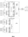
- FIG. 4 is a schematic diagram of a distributed antenna system 400 according to a fourth embodiment of the present disclosure.
- the distributed antenna system 400 comprises a first access unit 410, a plurality of remote units 420-1 to 420-n (collectively referred to as 420), a network extension unit 440 and a second access unit 450.
- the first access unit 410 and the second access unit 450 are coupled via a digital optical fiber 460.
- the first access unit 410, the plurality of remote units 420 and the network extension unit 440 are coupled via an analog optical fiber 430, and the network extension unit 440 is coupled between the first access unit 410 and the plurality of remote units 420.
- one network extension unit 440 is shown in FIG. 4 , this is only an example, and the number of network extension units may be plural.
- first access unit 410 may include first ports 411-1 and 411-2, first analog-to-digital conversion units 412-1 and 412-2, a first digital processing unit 413, a first digital-to-analog conversion unit 414-1 and 412-2, an analog optical module 415, second analog-to-digital conversion units 416-1 and 416-2, second digital-to-analog conversion units 417-1 and 417-2, a combining unit 418, a splitting unit 419 and a first digital optical module 470.
- first ports 411-1 and 411-2 first analog-to-digital conversion units 412-1 and 412-2, a first digital processing unit 413, a first digital-to-analog conversion unit 414-1 and 412-2, an analog optical module 415, second analog-to-digital conversion units 416-1 and 416-2, second digital-to-analog conversion units 417-1 and 417-2, a combining unit 418, a splitting unit 419 and a first digital optical module 470.
- first ports 411-1 and 411-2, the first analog-to-digital conversion units 412-1 and 412-2, the first digital processing unit 413, the first digital-to-analog conversion units 414-1 and 412-2, the analog optical module 415, the second analog-to-digital conversion units 416-1 and 416-2, the second digital-to-analog conversion units 417-1 and 417-2, the combining unit 418, the splitting unit 419 and the first digital optical module 470 are similar to those in FIG. 2 and FIG. 3 , which can be known from the preceding text and will not be repeated here anymore.
- the distributed antenna system 400 further comprises two splitting and combining units 403-1 and 403-2 (hereinafter collectively referred to as 403). It should be appreciated that although FIG. 4 shows two splitting and combining units, this is only an example, and there may be more splitting and combining units.
- the second access unit 450 may include two second ports 451-1 and 451-2 (hereinafter collectively referred to as 451), the third analog-to-digital conversion unit 452-1 and 452-2, the third digital-to-analog conversion unit 455-1 and 455-2, a second digital processing unit 453 and second digital optical module 454, the connection relationship of which is similar to those in FIG. 2 , which can be known from the preceding text and will not be repeated here anymore.
- Each splitting and combining unit 403 is coupled between four second base stations (base station 9, base station 10, base station 11, base station 12, or base station 13, base station 14, base station 15, base station 16) and the corresponding second port 451.
- the splitting and combining unit 403-1 is coupled between the four second base stations (base stations 9-12) and the corresponding second ports 451-1
- the splitting and combining unit 403-2 is coupled between the four second base stations (base stations 13-16) and the corresponding second ports 451-2. It should be appreciated that although FIG. 4 shows that each splitting and combining unit 403 is coupled to four first base stations, this is only an example, and each splitting and combining unit 403 may also be coupled to other numbers of first base stations.
- Each splitting and combining unit 403 is configured to combine a plurality of downlink analog radio frequency signals with the same frequency band from a plurality of second base stations to generate a third downlink analog radio frequency signal to output to a corresponding second port 451.
- Each splitting and combining unit 403 is further configured to split the third uplink analog radio frequency signal from the corresponding second port 451 to output to a plurality of second base stations. In this way, combination processing is performed on the downlink analog radio frequency signals having the same frequency band from the plurality of second base stations, thereby improving the efficiency.
- the two second ports 451 are used to receive two third downlink analog radio frequency signals from the two splitting and combining units 403 respectively. It should be understood that although FIG. 4 shows that the numbers of the first ports, the second ports, the third downlink analog radio frequency signals, the third analog-to-digital conversion units and the third digital-to-analog conversion unit are all two, this is only an example, the number of the first ports, the second ports and the third downlink analog radio frequency signals may be more than two, and the scope of the present disclosure is not limited herein.
- the third analog-to-digital conversion unit 452-1 and the third digital-to-analog conversion unit 455-1 are coupled to the second port 451-1 via a duplexer or radio frequency switch circuit 456-1.
- the duplexer is used to receive the third uplink analog radio frequency signal from the third digital-to-analog conversion unit 455-1, and transmit the signal to the second port 451-1.
- the duplexer is further configured to receive the third downlink analog radio frequency signal from the second port 451-1 and transmit the signal to the third analog-to-digital conversion unit 452-1.
- the radio frequency switch circuit is used to connect the second port 451-1 with the third digital-to-analog conversion unit 455-1 when receiving the third uplink analog radio frequency signal, to convert the third uplink analog radio frequency signal from the third digital-to-analog conversion unit 455-1.
- the radio frequency switch circuit is also used to connect the second port 451-1 with the third analog-to-digital conversion unit 452-1 when sending the third downlink analog radio frequency signal, to transmit the third downlink analog radio frequency signal from the second port 451-1 to the third analog-to-digital conversion unit 452-1.
- the third analog-to-digital conversion unit 452-2, the third digital-to-analog conversion unit 455-2, the duplexer or radio frequency switch circuit 456-2, and the second port 451-2 are also similar, and will not be repeated here.
- a radio frequency analog amplifying circuit may be provided between the radio frequency switch circuit or duplexer 456-1 and the third analog-to-digital conversion unit 452-1, to amplify the third downlink analog radio frequency signal.
- an analog radio frequency amplifying circuit may also be provided between the radio frequency switch circuit or duplexer 456-2 and the third analog-to-digital conversion unit 452-2.
- a radio frequency analog amplifying circuit may be provided between the radio frequency switch circuit or duplexer 456-1 and the third digital-to-analog conversion unit 455-1 and configured to amplify the third uplink analog radio frequency signal.
- a radio frequency analog amplifying circuit may be provided between the radio frequency switch circuit or duplexer 456-2 and the third digital-to-analog conversion unit 455-2.
- the third analog-to-digital conversion unit and the third digital-to-analog conversion unit are shown as separate units herein, this is only an example, and the third analog-to-digital conversion unit and the third digital-to-analog conversion unit may also be integrated as analog-to-digital/digital-to-analog conversion unit.
- the third analog-to-digital conversion unit 452-1 and the third digital-to-analog conversion unit 455-1 may be integrated as one analog-to-digital/digital-to-analog conversion unit
- the third analog-to-digital conversion unit 452-2 and the third digital-to-analog conversion unit 455-2 may be integrated as another analog-to-digital/digital-to-analog conversion unit.
- the third analog-to-digital conversion unit 452-1, the third digital-to-analog conversion unit 455-1, the third analog-to-digital conversion unit 452-2 and the third digital-to-analog conversion unit 455-2 may be integrated as one analog-to-digital/digital-to-analog conversion unit.
- the coupling between the first access unit and the second access unit may be achieved through a digital optical fiber, the first access unit may serve as a master access unit, and the second access unit may serve as a slave access unit, and the number of coupled base stations may be increased, thereby achieving source extension and source prolonging of the downlink signal and the receiver extension and receiver prolonging of the uplink signal.
- the first access unit, the network extension unit and the remote unit may employ star-type networking applications, and the topology is flexible and supports 1T1R, 2T2R and 4T4R mixed network networking topology, which is convenient for the flexible application of the system network.
- the access of multi-base station signals can be achieved, joint access of multiple network standards, multiple network frequency bands and multi-type network services can be enabled, and digitalized signal processing is enabled, which facilitates the balance of signal coverage of various operators in the sharing and co-construction.
- FIG. 5 shows a schematic diagram of a distributed antenna system 500 according to a fifth embodiment of the present disclosure.
- the distributed antenna system 500 does not include a network extension unit, a first access unit 510, remote units 520-1 to 520-n, an analog optical fiber 530, radio frequency switch circuits or duplexers 501-1 and 501-2, splitting and combining units 502-1 and 502-2, first ports 511-1 and 511-2, first analog-to-digital conversion units 512-1 and 512-2, a first digital processing unit 513, first digital-to-analog conversion units 514-1 and 514-2, an analog optical module 515, second analog-to-digital conversion units 516-1 and 516-2, and second digital-to-analog conversion unit 517 -1 and 517-2, a combining unit 518 and a splitting unit 519 included by the distributed antenna system 500 are similar to those in FIG. 3 , and may be known from the preceding text and will not be repeated any more here.
- FIG. 6 shows a schematic diagram of a distributed antenna system 600 according to a sixth embodiment of the present disclosure.
- the distributed antenna system 600 does not include a network extension unit, a first access unit 610, remote units 620-1 to 620-n, an analog optical fiber 630, radio frequency switch circuits or duplexers 601-1 and 601-2, splitting and combining units 602-1 and 602-2, first ports 611-1 and 611-2, first analog-to-digital conversion units 612-1 and 612 -2, a first digital processing unit 613, first digital-to-analog conversion units 614-1 and 614-2, an analog optical module 615, second analog-to-digital conversion units 616-1 and 616-2, second digital-to-analog conversion unit 617-1 and 617-2, a combining unit 618, a splitting unit 619, a second access unit 650, a first digital optical module 670, a second digital optical module 654, splitting and combining units 603-1 and 603-2, second ports 6
- Embodiments of the present disclosure further provide a communication system comprising: one or more base stations; and the distributed antenna system according to embodiments of the present disclosure, the distributed antenna system coupled to the one or more base stations.
Landscapes
- Engineering & Computer Science (AREA)
- Computer Networks & Wireless Communication (AREA)
- Signal Processing (AREA)
- Physics & Mathematics (AREA)
- Electromagnetism (AREA)
- Optical Communication System (AREA)
- Mobile Radio Communication Systems (AREA)
Claims (11)
- Ein verteiltes Antennensystem (100), umfassend:
eine erste Zugriffseinheit (110) und eine entfernte Einheit (120), wobei die erste Zugriffseinheit und die entfernte Einheit über eine analoge optische Faser (130) miteinander gekoppelt sind, und die erste Zugriffseinheit umfasst:einen ersten Port (111), der so konfiguriert ist, dass er ein erstes analoges Downlink-Funkfrequenzsignal von einer ersten Basisstation empfängt;eine erste Analog-Digital-Umsetzungseinheit (112), die mit dem ersten Anschluss gekoppelt und so konfiguriert ist, dass sie eine Analog-Digital-Umsetzung an dem ersten analogen Downlink-Funkfrequenzsignal durchführt, um ein erstes digitales Downlink-Signal zu erzeugen;eine erste digitale Verarbeitungseinheit (113), die mit der ersten Analog-Digital-Wandlereinheit gekoppelt und so konfiguriert ist, dass sie eine digitale Signalverarbeitung an dem ersten digitalen Downlink-Signal durchführt, um ein zweites digitales Downlink-Signal zu erzeugen;eine erste Digital-Analog-Wandlereinheit (114), die mit der ersten digitalen Verarbeitungseinheit gekoppelt und so konfiguriert ist, dass sie eine Digital-Analog-Wandlung des zweiten digitalen Downlink-Signals durchführt, um ein zweites analoges Downlink-Funkfrequenzsignal zu erzeugen;ein analoges optisches Modul (115), das mit der ersten Digital-Analog-Wandlereinheit gekoppelt und so konfiguriert ist, dass es eine elektrooptische Umwandlung des zweiten analogen Abwärtsstrecken-Funkfrequenzsignals durchführt, um ein erstes analoges optisches Abwärtsstreckensignal zu erzeugen, das über die analoge optische Faser an die entfernte Einheit übertragen wird, und ferner so konfiguriert ist, dass es ein analoges optisches Aufwärtsstreckensignal von der entfernten Einheit empfängt und das analoge optische Aufwärtsstreckensignal in ein erstes analoges Aufwärtsstrecken-Funkfrequenzsignal umwandelt;eine zweite Analog-Digital-Wandlereinheit (116), die mit dem analogen optischen Modul gekoppelt und so konfiguriert ist, dass sie eine Analog-Digital-Wandlung an dem ersten analogen Uplink-Funkfrequenzsignal durchführt, um ein erstes digitales Uplink-Signal zu erzeugen;die erste digitale Verarbeitungseinheit (113), die ferner mit der zweiten Analog-Digital-Wandlereinheit gekoppelt und ferner so konfiguriert ist, dass sie eine digitale Signalverarbeitung an dem ersten digitalen Signal der Aufwärtsstrecke durchführt, um ein zweites digitales Signal der Aufwärtsstrecke zu erzeugen;und eine zweite Digital-Analog-Wandlereinheit (117), die mit der ersten Digitalverarbeitungseinheit und dem ersten Anschluss gekoppelt und ferner so konfiguriert ist, dass sie eine Digital-Analog-Wandlung an dem zweiten Uplink-Digitalsignal durchführt, um ein zweites analoges Uplink-Funkfrequenzsignal zu erzeugen, das über den ersten Anschluss an die erste Basisstation übertragen wird. - Verteiltes Antennensystem nach Anspruch 1, wobei die erste Zugangseinheit ferner ein erstes digitales optisches Modul umfasst, das mit der ersten digitalen Verarbeitungseinheit gekoppelt ist, und das verteilte Antennensystem ferner eine zweite Zugangseinheit umfasst, wobei die zweite Zugangseinheit umfasst:einen zweiten Port, der so konfiguriert ist, dass er ein drittes analoges Downlink-Funkfrequenzsignal von einer zweiten Basisstation empfängt;eine dritte Analog-Digital-Umsetzungseinheit, die mit dem zweiten Anschluss gekoppelt und so konfiguriert ist, dass sie eine Analog-Digital-Umsetzung an dem dritten analogen Abwärtsstrecken-Funkfrequenzsignal durchführt, um ein drittes digitales Abwärtsstrecken-Signal zu erzeugen;eine zweite digitale Verarbeitungseinheit, die mit der dritten Analog-Digital-Wandlereinheit gekoppelt und so konfiguriert ist, dass sie an dem dritten digitalen Downlink-Signal eine digitale Signalverarbeitung durchführt, um ein viertes digitales Downlink-Signal zu erzeugen;ein zweites digitales optisches Modul, das mit der zweiten digitalen Verarbeitungseinheit gekoppelt ist und über eine digitale optische Faser mit dem ersten digitalen optischen Modul gekoppelt ist und so konfiguriert ist, dass es eine elektro-optische Umwandlung des vierten digitalen Downlink-Signals durchführt, um ein digitales optisches Downlink-Signal zu erzeugen, das über die digitale optische Faser an das erste digitale optische Modul übertragen wird.
- Verteiltes Antennensystem nach Anspruch 2, wobei das erste digitale optische Modul so konfiguriert ist, dass es eine photoelektrische Umwandlung des digitalen optischen Signals der Abwärtsstrecke durchführt, um ein fünftes digitales Signal der Abwärtsstrecke zu erzeugen;
die erste digitale Verarbeitungseinheit ist ferner so konfiguriert, dass sie eine digitale Signalverarbeitung an dem ersten digitalen Downlink-Signal und dem fünften digitalen Downlink-Signal durchführt, um das zweite digitale Downlink-Signal zu erzeugen. - Verteiltes Antennensystem nach Anspruch 2, wobei das erste digitale optische Modul ferner so konfiguriert ist, dass es eine elektrooptische Umwandlung des zweiten digitalen Uplink-Signals durchführt, um ein digitales optisches Uplink-Signal zu erzeugen, wobei das zweite digitale optische Modul ferner so konfiguriert ist, dass es eine photoelektrische Umwandlung des digitalen optischen Uplink-Signals durchführt, um ein drittes digitales Uplink-Signal zu erzeugen, wobei die zweite digitale Verarbeitungseinheit ferner so konfiguriert ist, dass sie eine digitale Signalverarbeitung des dritten digitalen Uplink-Signals durchführt, um ein viertes digitales Uplink-Signal zu erzeugen, und wobei die zweite Zugangseinheit ferner Folgendes umfasst
eine dritte Digital-Analog-Wandlereinheit, die mit der zweiten digitalen Verarbeitungseinheit gekoppelt und so konfiguriert ist, dass sie eine Digital-Analog-Wandlung an dem vierten digitalen Uplink-Signal durchführt, um ein drittes analoges Uplink-Funkfrequenzsignal zu erzeugen, das über den zweiten Anschluss an die zweite Basisstation übertragen wird. - Verteiltes Antennensystem nach einem der Ansprüche 1 bis 4, wobei mehrere entfernte Einheiten vorhanden sind und das verteilte Antennensystem ferner eine Netzerweiterungseinheit umfasst, die zwischen der ersten Zugangseinheit und den mehreren entfernten Einheiten über die analoge optische Faser gekoppelt ist.
- Verteiltes Antennensystem nach einem der Ansprüche 1 bis 4, wobei eine Vielzahl der ersten Ports, eine Vielzahl der ersten Basisstationen, eine Vielzahl der ersten analogen Abwärtsstrecken-Funkfrequenzsignale, eine Vielzahl der zweiten analogen Abwärtsstrecken-Funkfrequenzsignale, eine Vielzahl der ersten Analog-Digital-Wandlereinheiten und eine Vielzahl der ersten Digital-Analog-Wandlereinheiten vorhanden sind und die erste Zugangseinheit ferner Folgendes umfasst:eine Kombiniereinheit, die zwischen der Mehrzahl der ersten Digital-Analog-Wandlereinheiten und den analogen optischen Modulen gekoppelt und so konfiguriert ist, dass sie die Mehrzahl der zweiten analogen Abwärtsstrecken-Funkfrequenzsignale kombiniert, um ein kombiniertes analoges Abwärtsstrecken-Funkfrequenzsignal zu erzeugen;und das analog-optische Modul ist ferner so konfiguriert, dass es eine elektro-optische Umwandlung des kombinierten analogen Abwärtsstrecken-Funkfrequenzsignals durchführt, um das erste analoge optische Abwärtsstreckensignal zu erzeugen, das über die analoge optische Faser an die entfernte Einheit übertragen wird.
- Verteiltes Antennensystem nach Anspruch 6, wobei eine Vielzahl von zweiten Analog-Digital-Wandlereinheiten und eine Vielzahl von zweiten Digital-Analog-Wandlereinheiten vorhanden sind und die erste Zugangseinheit ferner Folgendes umfasst:eine Aufteilungseinheit, die mit der Mehrzahl von zweiten Analog-Digital-Wandlereinheiten und dem analogen optischen Modul gekoppelt ist und konfiguriert ist, um das erste analoge Uplink-Funkfrequenzsignal aufzuteilen, um eine Mehrzahl von aufgeteilten analogen Uplink-Funkfrequenzsignalen zu erzeugen;und die mehreren zweiten Analog-Digital-Wandlereinheiten, die so konfiguriert sind, dass sie eine Analog-Digital-Wandlung an den mehreren aufgeteilten analogen Uplink-Funkfrequenzsignalen durchführen, um mehrere erste digitale Uplink-Signale zu erzeugen.
- Verteiltes Antennensystem nach Anspruch 7, wobei das verteilte Antennensystem ferner umfasst:
eine Vielzahl von Aufteilungs- und Kombinationseinheiten, wobei jede der Vielzahl von Aufteilungs- und Kombinationseinheiten zwischen die Vielzahl von ersten Basisstationen und die entsprechenden ersten Ports gekoppelt ist, wobei jede Aufteilungs- und Kombinationseinheit so konfiguriert ist, dass sie eine Vielzahl von analogen Abwärtsstrecken-Funkfrequenzsignalen mit demselben Frequenzband von der Vielzahl von ersten Basisstationen kombiniert, um das erste analoge Abwärtsstrecken-Funkfrequenzsignal zu erzeugen, das an den entsprechenden ersten Port ausgegeben werden soll, und wobei jede der Aufteilungs- und Kombinationseinheiten ferner so konfiguriert ist, dass sie das zweite analoge Aufwärtsstrecken-Funkfrequenzsignal von dem entsprechenden ersten Port aufteilt, um es an die Vielzahl von ersten Basisstationen auszugeben. - Verteiltes Antennensystem nach Anspruch 6, wobei die mehreren ersten analogen Downlink-Funkfrequenzsignale mindestens eines der folgenden Merkmale aufweisen: einen oder mehrere Netzstandards, ein oder mehrere Netzfrequenzbänder und einen oder mehrere Diensttypen.
- Verteiltes Antennensystem nach Anspruch 9, wobei die erste digitale Verarbeitungseinheit ferner so konfiguriert ist, dass sie mindestens eine digitale Filterung oder einen digitalen Leistungsausgleich an dem ersten digitalen Downlink-Signal durchführt, um das zweite digitale Downlink-Signal zu erzeugen.
- Ein Kommunikationssystem, wobei das Kommunikationssystem umfasst:eine oder mehrere Basisstationen;und das verteilte Antennensystem nach einem der Ansprüche 1-10, wobei das verteilte Antennensystem mit der einen oder den mehreren Basisstationen gekoppelt ist.
Applications Claiming Priority (1)
| Application Number | Priority Date | Filing Date | Title |
|---|---|---|---|
| CN202123300973.1U CN215871428U (zh) | 2021-12-27 | 2021-12-27 | 一种分布式天线系统及通信系统 |
Publications (3)
| Publication Number | Publication Date |
|---|---|
| EP4142186A1 EP4142186A1 (de) | 2023-03-01 |
| EP4142186C0 EP4142186C0 (de) | 2024-06-05 |
| EP4142186B1 true EP4142186B1 (de) | 2024-06-05 |
Family
ID=80263351
Family Applications (1)
| Application Number | Title | Priority Date | Filing Date |
|---|---|---|---|
| EP22170871.2A Active EP4142186B1 (de) | 2021-12-27 | 2022-04-29 | Verteiltes antennensystem und kommunikationssystem |
Country Status (5)
| Country | Link |
|---|---|
| US (1) | US11522611B1 (de) |
| EP (1) | EP4142186B1 (de) |
| CN (1) | CN215871428U (de) |
| ES (1) | ES2985845T3 (de) |
| WO (1) | WO2023124175A1 (de) |
Citations (2)
| Publication number | Priority date | Publication date | Assignee | Title |
|---|---|---|---|---|
| US9614629B2 (en) * | 2012-08-15 | 2017-04-04 | Commscope Technologies Llc | Telecommunication system using multiple Nyquist zone operations |
| US10693550B2 (en) * | 2017-12-11 | 2020-06-23 | RF DSP Inc. | Enhanced customer premise equipment |
Family Cites Families (13)
| Publication number | Priority date | Publication date | Assignee | Title |
|---|---|---|---|---|
| US8396368B2 (en) * | 2009-12-09 | 2013-03-12 | Andrew Llc | Distributed antenna system for MIMO signals |
| US20110223958A1 (en) * | 2010-03-10 | 2011-09-15 | Fujitsu Limited | System and Method for Implementing Power Distribution |
| EP2602948A1 (de) * | 2011-12-05 | 2013-06-12 | Alcatel Lucent | Verfahren zur Verarbeitung eines digitalen Übertragungssignals, Verfahren zur Verarbeitung einer optischen Dateneinheit nach Empfang und Netzwerkelement für ein Telekommunikationsnetzwerk |
| CN102710361B (zh) * | 2012-06-01 | 2015-09-30 | 华为技术有限公司 | 一种分布式基站信号传输系统及通信系统 |
| WO2014061552A1 (ja) * | 2012-10-19 | 2014-04-24 | 日本電信電話株式会社 | 分散型無線通信基地局システム、信号処理装置、無線装置、及び分散型無線通信基地局システムの動作方法 |
| CN105874824B (zh) * | 2014-01-06 | 2020-05-22 | 大力系统有限公司 | 用于分布式天线网络的网络交换机 |
| EP3132651B1 (de) * | 2014-04-15 | 2018-10-17 | Telefonaktiebolaget LM Ericsson (publ) | Erster netzwerkknoten, zweiter netzwerkknoten und verfahren darin |
| US20160087745A1 (en) * | 2014-09-23 | 2016-03-24 | Corning Optical Communications Wireless Ltd | Supporting an add-on remote unit (ru) in an optical fiber-based distributed antenna system (das) over an existing optical fiber communications medium using wavelength division multiplexing (wdm) |
| WO2016075696A1 (en) * | 2014-11-13 | 2016-05-19 | Corning Optical Communications Wireless Ltd. | Analog distributed antenna systems (dass) supporting distribution of digital communications signals interfaced from a digital signal source and analog radio frequency (rf) communications signals |
| WO2016098111A1 (en) * | 2014-12-18 | 2016-06-23 | Corning Optical Communications Wireless Ltd. | Digital- analog interface modules (da!ms) for flexibly.distributing digital and/or analog communications signals in wide-area analog distributed antenna systems (dass) |
| CN105142155B (zh) * | 2015-07-13 | 2018-11-23 | 广州杰赛科技股份有限公司 | 光纤分布系统及方法 |
| WO2018012863A1 (ko) * | 2016-07-15 | 2018-01-18 | 주식회사 케이티 | 차세대 인빌딩 중계 시스템 및 방법 |
| CN113872695B (zh) * | 2021-12-06 | 2022-04-01 | 罗森伯格技术有限公司 | 一种分布式天线系统和通信系统 |
-
2021
- 2021-12-27 CN CN202123300973.1U patent/CN215871428U/zh active Active
-
2022
- 2022-04-29 EP EP22170871.2A patent/EP4142186B1/de active Active
- 2022-04-29 ES ES22170871T patent/ES2985845T3/es active Active
- 2022-05-21 US US17/750,310 patent/US11522611B1/en active Active
- 2022-08-31 WO PCT/CN2022/116038 patent/WO2023124175A1/zh not_active Ceased
Patent Citations (2)
| Publication number | Priority date | Publication date | Assignee | Title |
|---|---|---|---|---|
| US9614629B2 (en) * | 2012-08-15 | 2017-04-04 | Commscope Technologies Llc | Telecommunication system using multiple Nyquist zone operations |
| US10693550B2 (en) * | 2017-12-11 | 2020-06-23 | RF DSP Inc. | Enhanced customer premise equipment |
Also Published As
| Publication number | Publication date |
|---|---|
| CN215871428U (zh) | 2022-02-18 |
| EP4142186C0 (de) | 2024-06-05 |
| ES2985845T3 (es) | 2024-11-07 |
| EP4142186A1 (de) | 2023-03-01 |
| US11522611B1 (en) | 2022-12-06 |
| WO2023124175A1 (zh) | 2023-07-06 |
Similar Documents
| Publication | Publication Date | Title |
|---|---|---|
| US8027699B2 (en) | Systems and methods of band amplification with a shared amplifier | |
| US8743803B2 (en) | Spectrum allocation system and method for multi-band wireless RF data communications | |
| EP0492851B1 (de) | Mikrozellen-Übertragungssystem unter Verwendung von Raumdiversityempfang | |
| US5842117A (en) | Mobile radio aerial installation | |
| US20170289961A1 (en) | Multiple Access in Wireless Telecommunications System For High-Mobility Applications | |
| US11038541B2 (en) | Multi-frequency transceiver and base station | |
| JP2018519734A (ja) | アンテナアレイおよびネットワークデバイス | |
| US8090326B1 (en) | Communication signal transmission method, device, and system | |
| US8290536B2 (en) | Radio transceiver and method for reception of combined receive signals | |
| US20180310226A1 (en) | Main unit and distributed antenna system including the same | |
| US11522630B1 (en) | Distributed antenna system and communication system | |
| US20190028178A1 (en) | Base station signal matching device, and base station interface unit and distributed antenna system including the same | |
| US20130252671A1 (en) | Antenna system and base station system | |
| EP4142186A1 (de) | Verteiltes antennensystem und kommunikationssystem | |
| WO2014107567A1 (en) | Duplex filter arrangments for use with tunable narrow band antennas having forward and backward compatibilty | |
| US10574357B2 (en) | Headend for distributed antenna system and operating method thereof | |
| CN106848606A (zh) | 一种天线系统 | |
| US10264414B2 (en) | Asynchronous communication device for providing wireless broadband link between base station and plurality of client devices | |
| CN110224704B (zh) | 射频系统和基站设备 | |
| CN112585869B (zh) | 用于非同步tdd多频带操作的无线电单元 | |
| US9608847B2 (en) | Analog distributed antenna system for processing ethernet signal | |
| US20240072455A1 (en) | Methods and devices for antenna sharing using a radiohead in a distributed radio system | |
| CN206516739U (zh) | 一种低频基站双工器 | |
| EP4518186A1 (de) | Hochfrequenzisolationsmodul und kommunikationssystem | |
| EP1100212A1 (de) | Sende-/Empfangsgerät für elektromagnetische Signale |
Legal Events
| Date | Code | Title | Description |
|---|---|---|---|
| PUAI | Public reference made under article 153(3) epc to a published international application that has entered the european phase |
Free format text: ORIGINAL CODE: 0009012 |
|
| STAA | Information on the status of an ep patent application or granted ep patent |
Free format text: STATUS: THE APPLICATION HAS BEEN PUBLISHED |
|
| AK | Designated contracting states |
Kind code of ref document: A1 Designated state(s): AL AT BE BG CH CY CZ DE DK EE ES FI FR GB GR HR HU IE IS IT LI LT LU LV MC MK MT NL NO PL PT RO RS SE SI SK SM TR |
|
| STAA | Information on the status of an ep patent application or granted ep patent |
Free format text: STATUS: REQUEST FOR EXAMINATION WAS MADE |
|
| 17P | Request for examination filed |
Effective date: 20230331 |
|
| RBV | Designated contracting states (corrected) |
Designated state(s): AL AT BE BG CH CY CZ DE DK EE ES FI FR GB GR HR HU IE IS IT LI LT LU LV MC MK MT NL NO PL PT RO RS SE SI SK SM TR |
|
| STAA | Information on the status of an ep patent application or granted ep patent |
Free format text: STATUS: EXAMINATION IS IN PROGRESS |
|
| 17Q | First examination report despatched |
Effective date: 20230731 |
|
| GRAP | Despatch of communication of intention to grant a patent |
Free format text: ORIGINAL CODE: EPIDOSNIGR1 |
|
| STAA | Information on the status of an ep patent application or granted ep patent |
Free format text: STATUS: GRANT OF PATENT IS INTENDED |
|
| INTG | Intention to grant announced |
Effective date: 20240105 |
|
| GRAS | Grant fee paid |
Free format text: ORIGINAL CODE: EPIDOSNIGR3 |
|
| P01 | Opt-out of the competence of the unified patent court (upc) registered |
Effective date: 20240314 |
|
| GRAA | (expected) grant |
Free format text: ORIGINAL CODE: 0009210 |
|
| STAA | Information on the status of an ep patent application or granted ep patent |
Free format text: STATUS: THE PATENT HAS BEEN GRANTED |
|
| AK | Designated contracting states |
Kind code of ref document: B1 Designated state(s): AL AT BE BG CH CY CZ DE DK EE ES FI FR GB GR HR HU IE IS IT LI LT LU LV MC MK MT NL NO PL PT RO RS SE SI SK SM TR |
|
| REG | Reference to a national code |
Ref country code: CH Ref legal event code: EP |
|
| REG | Reference to a national code |
Ref country code: DE Ref legal event code: R096 Ref document number: 602022003757 Country of ref document: DE |
|
| REG | Reference to a national code |
Ref country code: IE Ref legal event code: FG4D |
|
| P04 | Withdrawal of opt-out of the competence of the unified patent court (upc) registered |
Free format text: CASE NUMBER: APP_40729/2024 Effective date: 20240709 |
|
| U01 | Request for unitary effect filed |
Effective date: 20240705 |
|
| U07 | Unitary effect registered |
Designated state(s): AT BE BG DE DK EE FI FR IT LT LU LV MT NL PT SE SI Effective date: 20240712 |
|
| PG25 | Lapsed in a contracting state [announced via postgrant information from national office to epo] |
Ref country code: HR Free format text: LAPSE BECAUSE OF FAILURE TO SUBMIT A TRANSLATION OF THE DESCRIPTION OR TO PAY THE FEE WITHIN THE PRESCRIBED TIME-LIMIT Effective date: 20240605 |
|
| PG25 | Lapsed in a contracting state [announced via postgrant information from national office to epo] |
Ref country code: GR Free format text: LAPSE BECAUSE OF FAILURE TO SUBMIT A TRANSLATION OF THE DESCRIPTION OR TO PAY THE FEE WITHIN THE PRESCRIBED TIME-LIMIT Effective date: 20240906 |
|
| PG25 | Lapsed in a contracting state [announced via postgrant information from national office to epo] |
Ref country code: NO Free format text: LAPSE BECAUSE OF FAILURE TO SUBMIT A TRANSLATION OF THE DESCRIPTION OR TO PAY THE FEE WITHIN THE PRESCRIBED TIME-LIMIT Effective date: 20240905 Ref country code: HR Free format text: LAPSE BECAUSE OF FAILURE TO SUBMIT A TRANSLATION OF THE DESCRIPTION OR TO PAY THE FEE WITHIN THE PRESCRIBED TIME-LIMIT Effective date: 20240605 Ref country code: GR Free format text: LAPSE BECAUSE OF FAILURE TO SUBMIT A TRANSLATION OF THE DESCRIPTION OR TO PAY THE FEE WITHIN THE PRESCRIBED TIME-LIMIT Effective date: 20240906 Ref country code: RS Free format text: LAPSE BECAUSE OF FAILURE TO SUBMIT A TRANSLATION OF THE DESCRIPTION OR TO PAY THE FEE WITHIN THE PRESCRIBED TIME-LIMIT Effective date: 20240905 |
|
| REG | Reference to a national code |
Ref country code: ES Ref legal event code: FG2A Ref document number: 2985845 Country of ref document: ES Kind code of ref document: T3 Effective date: 20241107 |
|
| P05 | Withdrawal of opt-out of the competence of the unified patent court (upc) changed |
Free format text: CASE NUMBER: APP_40729/2024 Effective date: 20240712 |
|
| PG25 | Lapsed in a contracting state [announced via postgrant information from national office to epo] |
Ref country code: PL Free format text: LAPSE BECAUSE OF FAILURE TO SUBMIT A TRANSLATION OF THE DESCRIPTION OR TO PAY THE FEE WITHIN THE PRESCRIBED TIME-LIMIT Effective date: 20240605 |
|
| PG25 | Lapsed in a contracting state [announced via postgrant information from national office to epo] |
Ref country code: IS Free format text: LAPSE BECAUSE OF FAILURE TO SUBMIT A TRANSLATION OF THE DESCRIPTION OR TO PAY THE FEE WITHIN THE PRESCRIBED TIME-LIMIT Effective date: 20241005 |
|
| PG25 | Lapsed in a contracting state [announced via postgrant information from national office to epo] |
Ref country code: CZ Free format text: LAPSE BECAUSE OF FAILURE TO SUBMIT A TRANSLATION OF THE DESCRIPTION OR TO PAY THE FEE WITHIN THE PRESCRIBED TIME-LIMIT Effective date: 20240605 |
|
| PG25 | Lapsed in a contracting state [announced via postgrant information from national office to epo] |
Ref country code: RO Free format text: LAPSE BECAUSE OF FAILURE TO SUBMIT A TRANSLATION OF THE DESCRIPTION OR TO PAY THE FEE WITHIN THE PRESCRIBED TIME-LIMIT Effective date: 20240605 Ref country code: SK Free format text: LAPSE BECAUSE OF FAILURE TO SUBMIT A TRANSLATION OF THE DESCRIPTION OR TO PAY THE FEE WITHIN THE PRESCRIBED TIME-LIMIT Effective date: 20240605 |
|
| PG25 | Lapsed in a contracting state [announced via postgrant information from national office to epo] |
Ref country code: SM Free format text: LAPSE BECAUSE OF FAILURE TO SUBMIT A TRANSLATION OF THE DESCRIPTION OR TO PAY THE FEE WITHIN THE PRESCRIBED TIME-LIMIT Effective date: 20240605 |
|
| PG25 | Lapsed in a contracting state [announced via postgrant information from national office to epo] |
Ref country code: SM Free format text: LAPSE BECAUSE OF FAILURE TO SUBMIT A TRANSLATION OF THE DESCRIPTION OR TO PAY THE FEE WITHIN THE PRESCRIBED TIME-LIMIT Effective date: 20240605 Ref country code: SK Free format text: LAPSE BECAUSE OF FAILURE TO SUBMIT A TRANSLATION OF THE DESCRIPTION OR TO PAY THE FEE WITHIN THE PRESCRIBED TIME-LIMIT Effective date: 20240605 Ref country code: RO Free format text: LAPSE BECAUSE OF FAILURE TO SUBMIT A TRANSLATION OF THE DESCRIPTION OR TO PAY THE FEE WITHIN THE PRESCRIBED TIME-LIMIT Effective date: 20240605 Ref country code: PL Free format text: LAPSE BECAUSE OF FAILURE TO SUBMIT A TRANSLATION OF THE DESCRIPTION OR TO PAY THE FEE WITHIN THE PRESCRIBED TIME-LIMIT Effective date: 20240605 Ref country code: IS Free format text: LAPSE BECAUSE OF FAILURE TO SUBMIT A TRANSLATION OF THE DESCRIPTION OR TO PAY THE FEE WITHIN THE PRESCRIBED TIME-LIMIT Effective date: 20241005 Ref country code: CZ Free format text: LAPSE BECAUSE OF FAILURE TO SUBMIT A TRANSLATION OF THE DESCRIPTION OR TO PAY THE FEE WITHIN THE PRESCRIBED TIME-LIMIT Effective date: 20240605 |
|
| PLBE | No opposition filed within time limit |
Free format text: ORIGINAL CODE: 0009261 |
|
| STAA | Information on the status of an ep patent application or granted ep patent |
Free format text: STATUS: NO OPPOSITION FILED WITHIN TIME LIMIT |
|
| U20 | Renewal fee for the european patent with unitary effect paid |
Year of fee payment: 4 Effective date: 20250325 |
|
| 26N | No opposition filed |
Effective date: 20250306 |
|
| PGFP | Annual fee paid to national office [announced via postgrant information from national office to epo] |
Ref country code: ES Payment date: 20250512 Year of fee payment: 4 |
|
| REG | Reference to a national code |
Ref country code: CH Ref legal event code: H13 Free format text: ST27 STATUS EVENT CODE: U-0-0-H10-H13 (AS PROVIDED BY THE NATIONAL OFFICE) Effective date: 20251125 |
|
| PG25 | Lapsed in a contracting state [announced via postgrant information from national office to epo] |
Ref country code: MC Free format text: LAPSE BECAUSE OF FAILURE TO SUBMIT A TRANSLATION OF THE DESCRIPTION OR TO PAY THE FEE WITHIN THE PRESCRIBED TIME-LIMIT Effective date: 20240605 |
|
| PG25 | Lapsed in a contracting state [announced via postgrant information from national office to epo] |
Ref country code: CH Free format text: LAPSE BECAUSE OF NON-PAYMENT OF DUE FEES Effective date: 20250430 |
|
| PG25 | Lapsed in a contracting state [announced via postgrant information from national office to epo] |
Ref country code: IE Free format text: LAPSE BECAUSE OF NON-PAYMENT OF DUE FEES Effective date: 20250429 |