EP4142151B1 - Class d power amplification modulation system for self-adaptive adjustment of audio signal, method, device, processor and storage medium - Google Patents
Class d power amplification modulation system for self-adaptive adjustment of audio signal, method, device, processor and storage medium Download PDFInfo
- Publication number
- EP4142151B1 EP4142151B1 EP21912990.5A EP21912990A EP4142151B1 EP 4142151 B1 EP4142151 B1 EP 4142151B1 EP 21912990 A EP21912990 A EP 21912990A EP 4142151 B1 EP4142151 B1 EP 4142151B1
- Authority
- EP
- European Patent Office
- Prior art keywords
- audio signal
- signal
- circuit module
- frequency
- amplitude
- Prior art date
- Legal status (The legal status is an assumption and is not a legal conclusion. Google has not performed a legal analysis and makes no representation as to the accuracy of the status listed.)
- Active
Links
Images
Classifications
-
- H—ELECTRICITY
- H03—ELECTRONIC CIRCUITRY
- H03F—AMPLIFIERS
- H03F3/00—Amplifiers with only discharge tubes or only semiconductor devices as amplifying elements
- H03F3/20—Power amplifiers, e.g. Class B amplifiers, Class C amplifiers
- H03F3/21—Power amplifiers, e.g. Class B amplifiers, Class C amplifiers with semiconductor devices only
- H03F3/217—Class D power amplifiers; Switching amplifiers
-
- H—ELECTRICITY
- H03—ELECTRONIC CIRCUITRY
- H03F—AMPLIFIERS
- H03F3/00—Amplifiers with only discharge tubes or only semiconductor devices as amplifying elements
- H03F3/20—Power amplifiers, e.g. Class B amplifiers, Class C amplifiers
- H03F3/21—Power amplifiers, e.g. Class B amplifiers, Class C amplifiers with semiconductor devices only
- H03F3/217—Class D power amplifiers; Switching amplifiers
- H03F3/2175—Class D power amplifiers; Switching amplifiers using analogue-digital or digital-analogue conversion
-
- H—ELECTRICITY
- H03—ELECTRONIC CIRCUITRY
- H03F—AMPLIFIERS
- H03F1/00—Details of amplifiers with only discharge tubes, only semiconductor devices or only unspecified devices as amplifying elements
- H03F1/02—Modifications of amplifiers to raise the efficiency, e.g. gliding Class A stages, use of an auxiliary oscillation
- H03F1/0205—Modifications of amplifiers to raise the efficiency, e.g. gliding Class A stages, use of an auxiliary oscillation in transistor amplifiers
- H03F1/0261—Modifications of amplifiers to raise the efficiency, e.g. gliding Class A stages, use of an auxiliary oscillation in transistor amplifiers with control of the polarisation voltage or current, e.g. gliding Class A
- H03F1/0266—Modifications of amplifiers to raise the efficiency, e.g. gliding Class A stages, use of an auxiliary oscillation in transistor amplifiers with control of the polarisation voltage or current, e.g. gliding Class A by using a signal derived from the input signal
-
- H—ELECTRICITY
- H03—ELECTRONIC CIRCUITRY
- H03F—AMPLIFIERS
- H03F1/00—Details of amplifiers with only discharge tubes, only semiconductor devices or only unspecified devices as amplifying elements
- H03F1/30—Modifications of amplifiers to reduce influence of variations of temperature or supply voltage or other physical parameters
-
- H—ELECTRICITY
- H03—ELECTRONIC CIRCUITRY
- H03F—AMPLIFIERS
- H03F3/00—Amplifiers with only discharge tubes or only semiconductor devices as amplifying elements
- H03F3/181—Low-frequency amplifiers, e.g. audio preamplifiers
- H03F3/183—Low-frequency amplifiers, e.g. audio preamplifiers with semiconductor devices only
- H03F3/187—Low-frequency amplifiers, e.g. audio preamplifiers with semiconductor devices only in integrated circuits
-
- H—ELECTRICITY
- H03—ELECTRONIC CIRCUITRY
- H03F—AMPLIFIERS
- H03F3/00—Amplifiers with only discharge tubes or only semiconductor devices as amplifying elements
- H03F3/20—Power amplifiers, e.g. Class B amplifiers, Class C amplifiers
- H03F3/21—Power amplifiers, e.g. Class B amplifiers, Class C amplifiers with semiconductor devices only
- H03F3/213—Power amplifiers, e.g. Class B amplifiers, Class C amplifiers with semiconductor devices only in integrated circuits
-
- H—ELECTRICITY
- H03—ELECTRONIC CIRCUITRY
- H03F—AMPLIFIERS
- H03F2200/00—Indexing scheme relating to amplifiers
- H03F2200/03—Indexing scheme relating to amplifiers the amplifier being designed for audio applications
-
- H—ELECTRICITY
- H03—ELECTRONIC CIRCUITRY
- H03F—AMPLIFIERS
- H03F2200/00—Indexing scheme relating to amplifiers
- H03F2200/114—Indexing scheme relating to amplifiers the amplifier comprising means for electro-magnetic interference [EMI] protection
-
- H—ELECTRICITY
- H03—ELECTRONIC CIRCUITRY
- H03F—AMPLIFIERS
- H03F2200/00—Indexing scheme relating to amplifiers
- H03F2200/351—Pulse width modulation being used in an amplifying circuit
Definitions
- the present disclosure relates to the field of audio signal modulation, and in particular, to a Class D power amplification modulation system and a method for self-adaptive adjustment of an audio signal, a method, a device, and a processor for realizing self-adaptive adjustment and modulation of an audio signal of a Class D power amplifier and a computer-readable storage medium.
- US 2007/0285163 A1 discloses a method for amplifying a digital signal with reduced electromagnetic interference. An average amplitude detector controls the clock frequency of a pseudo-random number generator, so the clock signal decreases when the signal's average amplitude increases. The input signal and pseudo-random number generator generate a control signal for a switching power amplifier followed by a low-pass filter.
- US 2003/0035554 A1 discloses an audio amplifier using pulse width modulation.
- the amplifier's switching frequency or low pass filter cutoff frequency varies with the input signal's frequency.
- the method lowers the average switching frequency based on the input signal's bandwidth.
- the cutoff frequency is lowered to restore the output pulse.
- the amplifier uses different average switching frequencies for each channel in a multi-channel system, improving power efficiency and minimizing electromagnetic interference.
- US 2014/0133678 A1 discloses a circuit structure for implementing an adaptive function in a class-D audio power amplifier circuit.
- the circuit comprises an operation amplifier, a pulse width modulator, and a driver stage, sequentially and serially connected.
- the input terminal of the operation amplifier connects to an external audio signal output terminal.
- the output terminal of the driver stage connects to a loudspeaker and the input terminal of the operation amplifier via a feedback loop.
- the circuit also includes one or more of the following: a carrier adaptive circuit, a frequency adaptive circuit, a driver adaptive circuit, and a temperature adaptive circuit.
- TWI 707537 B discloses a D-class amplifier circuit comprising an input impedance, an operational amplifier, a voltage-adjusting circuit, a pulse-generating circuit, and a drive circuit. The input impedance is coupled to the operational amplifier, receiving an input voltage and outputting an input current.
- the operational amplifier outputs an amplified signal based on an input operating voltage and a feedback signal under the first power voltage.
- the voltage-adjusting circuit adjusts the input operating voltage.
- the pulse-generating circuit outputs a pulse width modulation (PWM) signal based on the amplified signal.
- the drive circuit generates a driving signal according to the PWM signal under the second power voltage.
- the feedback signal is related to the driving signal.
- US 2020/0395908 A1 describes configurable amplifier systems where the power supply rail of a linear amplifier, such as a class A amplifier, is modulated by a switching amplifier, like a class D amplifier. The switching amplifier can also operate independently of the linear amplifier. Techniques are provided for modulating the standing current of the output stage of a linear amplifier based on the input signal to the linear amplifier or the modulation of the power supply rail of the linear amplifier.
- a modulation circuit of a class D power amplifier is used to compare an audio signal with a carrier wave generated by a carrier generator to modulate the carrier wave into a pulse width modulation (PWM) wave. Both the frequency of the PWM wave and the direct current (DC) potential of the audio signal are determined by the carrier generator. 1. This results in that in an entire audio range, the PWM wave amplified by a switch transistor works at a certain frequency, which is the same as the frequency of the PWM signal.
- the frequency of the PWM wave should be set at more than ten times the highest frequency (i.e., 20 KHZ) of the audio signal, which results in that when the frequency of the audio signal is low, the frequency of the carrier wave is much greater than ten times the frequency of the audio signal, and the electromagnetic interference (EMI) of the circuit is large. Meanwhile, the switching frequency of a power transistor is fast, which affects the life of the power transistor and increases the power consumption of the circuit. 2. If the DC potentials of the audio signals are different and these audio signals are respectively compared with the same carrier wave to modulate into PWM waves, the duty cycles of the PWM waves are also different. That is, the switching time of the power transistor is different.
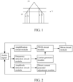
- FIG. 1 shows the duty cycles of the PWM waves obtained by comparing the DC potentials of the audio input signals with the carrier wave.
- the range of the carrier wave is 1 V - 5 V. Assuming that a 3 V DC signal is input, at this time, the duty cycle of the PWM wave is 50%. If the potential of the DC signal is 2 V, the duty cycle is 33.3%, a conduction time of the switch transistor in a carrier wave cycle is reduced by 16.7%, thereby improving the efficiency of the circuit.
- m and n represent the DC potential of the input signal, m ⁇ n, the duty cycle corresponding to m is a, and the duty cycle corresponding to n is (a+b). It can be seen that the smaller the DC potential is, the smaller the duty cycle is.
- the audio signal is a composite signal, which includes many signals of different frequencies. In the frequency spectrum, the amplitude of the audio signal is changing all the time. The amplitude or frequency of the audio signal is detected to adjust the duty cycle of the PWM wave of the Class D power amplifier, although the power consumption or EMI of the circuit can be reduced to a certain extent, there are limitations in the implementing and technical effects of the technical solution. In traditional technology, a high threshold comparator and a low threshold comparator are set for comparing an amplified audio signal, and only the frequency of the audio signal can be adjusted.
- an object of the present disclosure is to provide a Class D power amplification modulation system for self-adaptive adjustment of an audio signal, to solve at least one problem in the prior art.
- the present disclosure provides a Class D power amplification modulation system for self-adaptive adjustment of an audio signal according to claim 1.
- the amplitude detection circuit module includes: an amplitude detection analogy-to-digital converter (ADC) unit, configured to detect an amplitude of the audio signal and generate a digital signal corresponding to the amplitude of the audio signal; and an amplitude detection digital-to-analogy converter (DAC) unit, configured to perform analysis processing on the digital signal to generate an analog signal corresponding to the digital signal.
- ADC analogy-to-digital converter
- DAC amplitude detection digital-to-analogy converter
- a sampling frequency of the amplitude detection ADC unit is 1 MHz.
- the present disclosure provides a method for realizing self-adaptive adjustment and modulation of an audio signal of a Class D power amplifier according to claim 4.
- the amplitude detection circuit module includes an amplitude detection ADC unit and an amplitude detection DAC unit
- step (3) of claim 4 includes: detecting, by the amplitude detection ADC unit, an amplitude of the audio signal and generating a digital signal corresponding to the amplitude of the audio signal; and receiving and analyzing, by the amplitude detection DAC unit, the digital signal to generate an analog signal corresponding to the digital signal.
- the present disclosure provides a device for self-adaptive adjustment and modulation of an audio signal of a Class D power amplifier according to claim 8.
- the present disclosure provides a processor for realizing self-adaptive adjustment and modulation of an audio signal of a Class D power amplifier.
- the processor is configured to execute computer-executable instructions, when the computer-executable instructions are executed by the processor, steps of the method for realizing self-adaptive adjustment and modulation of the audio signal of the Class D power amplifier as mentioned above are implemented.
- the present disclosure provides a computer-readable storage medium storing a computer program.
- the computer program is executed by a processor, steps of the method for realizing self-adaptive adjustment and modulation of the audio signal of the Class D power amplifier as mentioned above are implemented.
- the present disclosure provides the Class D power amplification modulation system and the method for self-adaptive adjustment of the audio signal, the method, the device, and the processor for realizing self-adaptive adjustment and modulation of the audio signal of the Class D power amplifier and the computer-readable storage medium.
- the frequency detection circuit module detects the frequency of the audio signal, and the frequency of the carrier wave generated by the carrier generator module is adjusted according to the frequency of the audio signal. The higher the frequency of the audio signal, the higher the frequency of the carrier wave generated by the carrier generator module.
- the technical solution of the present disclosure adjusts the DC potential of the audio signal in real time, the duty cycle of the PWM signal varies with the DC potential of the audio signal, and the efficiency of the circuit is improved.
- the frequency of the carrier wave is adjusted according to the frequency of the audio signal. Both the power consumption and the EMI of the circuit of the present disclosure can be improved at the same time.
- the Class D power amplification modulation system includes: an amplification circuit module, connected to the audio signal, for amplifying the audio signal; a pulse width modulation (PWM) circuit module, connected to the amplification circuit module, for performing PWM processing on an amplified audio signal generated by the amplification circuit module to generate a PWM signal; a drive circuit module, connected to the PWM circuit module, for performing system drive processing on the PWM signal to feed back to the audio signal; a frequency detection circuit module, connected to the audio signal, for performing frequency detection processing on the audio signal; a carrier generator module, connected to the frequency detection circuit module and the PWM circuit module, for loading a signal generated after the frequency detection processing onto a carrier modulation signal to transmit the carrier modulation signal and the signal generated after the frequency detection processing to the PWM circuit module; an amplitude detection circuit module, connected to the audio signal, for performing amplitude detection processing
- the amplitude detection circuit module includes: an amplitude detection analogy-to-digital converter (ADC) unit, for detecting an amplitude of the audio signal and generating a digital signal corresponding to the amplitude of the audio signal; and an amplitude detection digital-to-analogy converter (DAC) unit, for performing analysis processing on the digital signal to generate an analog signal corresponding to the digital signal.
- ADC analogy-to-digital converter
- DAC amplitude detection digital-to-analogy converter
- a sampling frequency of the amplitude detection ADC unit is 1 MHz
- the present disclosure provides a method for realizing self-adaptive adjustment and modulation of an audio signal of a Class D power amplifier according to the Class D power amplification modulation system.
- the method includes: step (1), inputting the audio signal to the amplification circuit module, and performing amplification processing, by the amplification circuit module, on the audio signal; step (2), inputting the audio signal to the frequency detection circuit module, and performing frequency detection processing, by the frequency detection circuit module, on the audio signal; step (3), inputting the audio signal to the amplitude detection circuit module, and performing amplitude detection processing, by the amplitude detection circuit module, on the audio signal; step (4), transmitting, a signal generated after the frequency detection processing to the carrier generator module, loading, the signal generated after the frequency detection processing onto the carrier modulation signal, and transmitting the signal generated after the frequency detection processing and the carrier modulation signal to the PWM circuit module; step (5), performing, by the PWM circuit module, PWM processing on a signal generated after the amplification processing and a signal generated after the frequency
- the amplitude detection circuit module includes an amplitude detection ADC unit and an amplitude detection DAC unit.
- Step (3) includes: detecting, by the amplitude detection ADC unit, an amplitude of the audio signal and generating a digital signal corresponding to the amplitude of the audio signal; and receiving and analyzing, by the amplitude detection DAC unit, the digital signal to generate an analog signal corresponding to the digital signal.
- the present disclosure provides a method for realizing self-adaptive adjustment and modulation of an audio signal of a Class D power amplifier.
- the method includes: step (A), performing amplification processing, frequency detection processing and amplitude detection processing on the audio signal respectively; step (B), loading a signal generated after the frequency detection processing onto a carrier modulation signal, performing PWM processing on the signal generated after the frequency detection processing and the carrier modulation signal and a signal generated after the amplification processing, performing system drive processing on a signal generated after the PWM processing, and combining a signal generated after the system drive processing and the audio signal; and step (C), performing DC potential adjustment processing on a signal generated after the amplitude detection processing to generate a DC potential of the audio signal.
- the amplitude detection processing includes: detecting an amplitude of the audio signal to generate a digital signal corresponding to the amplitude of the audio signal, and performing analysis processing on the digital signal to generate an analog signal corresponding to the digital signal.
- the present disclosure provides a device for self-adaptive adjustment and modulation of an audio signal of a Class D amplifier.
- the device includes: a processor, configured to execute computer-executable instructions; and a memory, storing one or more of the computer-executable instructions.
- the memory implements steps of the method for self-adaptive adjustment and modulation of the audio signal of the Class D power amplifier as mentioned above.
- the present disclosure provides a processor for realizing self-adaptive adjustment and modulation of an audio signal of a Class D power amplifier.
- the processor is configured to execute computer-executable instructions, when the computer-executable instructions are executed by the processor, steps of the method for realizing self-adaptive adjustment and modulation of the audio signal of the Class D power amplifier as mentioned above.
- the present disclosure provides a computer-readable storage medium storing a computer program.
- the computer program is executed by a processor, the steps of the method for realizing self-adaptive adjustment and modulation of the audio signal of the Class D power amplifier as mentioned above are implemented.
- the amplification circuit module performs amplification processing on the audio signal
- the frequency detection circuit module detects the frequency of the audio signal.
- the frequency of the carrier wave generated by the carrier generator module is adjusted according to the frequency of the audio signal. The higher the frequency of the audio signal is, the higher the frequency of the carrier wave generated by the carrier generator module is.
- the audio signal processed respectively by the amplification circuit module and the frequency detection circuit module is sent to the PWM circuit module for modulation of the duty cycle of the PWM signal, and the signal processed by the PWM circuit module is sent to the drive circuit module for driving, and the signal processed by the drive circuit module is combined with the original audio signal.
- the amplitude detection circuit module detects the amplitude of the audio signal.
- the amplitude detection circuit module includes: the amplitude detection ADC unit, for detecting the amplitude of the audio signal and generating the digital signal corresponding to the amplitude of the audio signal; and the amplitude detection DAC unit, for performing analysis processing on the digital signal to generate the analog signal corresponding to the digital signal, and sending the analog signal to the DC potential adjustment module to generate the DC potential of the audio signal.
- the amplitude of the audio signal is proportional to a conduction time of the drive transistor in the drive circuit module. That is, the greater the amplitude of the audio signal is, the longer the conduction time of the drive transistor is.
- the frequency of the carrier wave of the carrier generator module is the same as that of the drive transistor, that is, the higher the frequency of the carrier wave is, the faster the switching frequency of the driver transistor is.
- the method for realizing self-adaptive adjustment and modulation of the audio signal of the Class D power amplifier of the present disclosure improves the characteristics of the circuit in the signal time domain and the frequency, minimizes power consumption of the signals in different amplitudes and frequencies, and improves EMI performance, or balances the power consumption and EMI characteristics.
- amplification processing, frequency detection processing and amplitude detection processing are performed on the audio signal respectively.
- the frequency of the carrier wave is adjusted according to the frequency of the audio signal. The higher the frequency of the audio signal is, the higher the frequency of the carrier wave is.
- the modulation of the duty cycle of the PWM signal is performed on the signal generated after the amplification processing and the signal generated after the frequency detection processing. Meanwhile, the amplitude of the audio signal is detected, a digital signal corresponding to the amplitude of the audio signal is generated, the digital signal is modulated into the analogy signal corresponding to the digital signal, and the DC potential adjustment processing is performed on the analogy signal to generate the DC potential of the audio signal.
- the duty cycle of the PWM signal varies with the DC potential of the audio signal. Meanwhile, when the DC potential of the audio signal is changed, the frequency of the carrier wave will be detected and adjusted, so that the power consumption and EMI of the circuit can be improved at the same time.
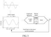
- the principle of the method for realizing self-adaptive adjustment and modulation of the audio signal of the Class D power amplifier is as follows: the amplitude detection ADC unit of the amplitude detection circuit module detects the amplitude of the analogy audio signal.
- the sampling frequency of the amplitude detection ADC unit is 1 MHz, which is much greater than the highest frequency (e.g., 20 KHz) of the audio signal. The sampling frequency should ensure the integrity of the collected data.
- the digital signal (including least significant bit (LSB) and most significant bit (MSB)) is obtained through detecting the amplitude of the audio signal.
- the amplitude detection DAC unit performs analysis processing on the digital signal to generate the analogy signal V0, and the analog signal V0 acts as the DC potential of the audio signal.
- the duty cycle of the PWM signal obtained after the audio signal is processed by the amplification circuit and the PWM circuit is changed. That is, the smaller the DC potential of the audio signals with the same amplitude and frequency is, the smaller the duty cycle of the PWM signal is, so that the conduction time of the drive transistor is short and the efficiency of the circuit is improved.
- the frequency detection circuit module detects the frequency of the audio signal, and the frequency of the carrier wave of the carrier generator module is adjusted according to the frequency of the audio signal.
- ADC/DAC By using ADC/DAC to detect the amplitude of the input signal, and the amplitude of the input signal (the audio signal) is analyzed into an analog signal to act as the DC potential of the input signal. The smaller the amplitude of the input signal is, the smaller the DC potential is.
- the frequency of the carrier wave signal is adjusted according to the frequency of the input signal. The greater the frequency of the input signal is, the greater the frequency of the carrier wave is.
- each functional unit in each embodiment of the present disclosure may be integrated in a processing module, or each unit may be physically present alone, or two or more units may be integrated in a single module.
- the above integrated module can be implemented either in the form of hardware or in the form of a software functional module.
- the integrated module can also be stored in a computer-readable storage medium if it is implemented as a software function module and sold or used as a stand-alone product.
- the storage medium mentioned above can be Read-Only Memory, disks or CD-ROMs, etc.
- the present disclosure provides the Class D power amplification modulation system and the method for self-adaptive adjustment of the audio signal, the method, the device, and the processor for realizing self-adaptive adjustment of the audio signal of the Class D power amplifier and the non-transitory computer-readable storage medium.
- the frequency detection circuit module detects the frequency of the audio signal, and the frequency of the carrier wave generated by the carrier generator module is adjusted according to the frequency of the audio signal. The higher the frequency of the audio signal, the higher the frequency of the carrier wave generated by the carrier generator module.
- the frequency of the carrier wave is improved by reducing the duty cycle, thereby improving the power consumption of the carrier wave with high frequency and improving the high frequency performance of the audio signal with small amplitude;
- the technical solution of the present disclosure adjusts the DC potential of the signal in real time, the duty cycle of PWM signal varies with the DC potential of the audio signal, and the efficiency of the circuit is improved.
- the frequency of the carrier wave signal is adjusted according to the frequency of the signal. Compared with adjusting the frequency of the signal only, the power consumption and EMI of the circuit of the present disclosure can be improved at the same time.
Landscapes
- Engineering & Computer Science (AREA)
- Power Engineering (AREA)
- Microelectronics & Electronic Packaging (AREA)
- Multimedia (AREA)
- Amplifiers (AREA)
Description
- This application claims priority to
Chinese Patent Application No. 202011622922.8, filed on December 30, 2020 - The present disclosure relates to the field of audio signal modulation, and in particular, to a Class D power amplification modulation system and a method for self-adaptive adjustment of an audio signal, a method, a device, and a processor for realizing self-adaptive adjustment and modulation of an audio signal of a Class D power amplifier and a computer-readable storage medium.
US 2007/0285163 A1 discloses a method for amplifying a digital signal with reduced electromagnetic interference. An average amplitude detector controls the clock frequency of a pseudo-random number generator, so the clock signal decreases when the signal's average amplitude increases. The input signal and pseudo-random number generator generate a control signal for a switching power amplifier followed by a low-pass filter. When the input signal's average amplitude falls below a predetermined threshold, the switching amplifier is placed in sleep mode.US 2003/0035554 A1 discloses an audio amplifier using pulse width modulation. The amplifier's switching frequency or low pass filter cutoff frequency varies with the input signal's frequency. The method lowers the average switching frequency based on the input signal's bandwidth. For signals with narrow bandwidth, like pulse width modulation type radio signals or subwoofer signals, the cutoff frequency is lowered to restore the output pulse. The amplifier uses different average switching frequencies for each channel in a multi-channel system, improving power efficiency and minimizing electromagnetic interference.US 2014/0133678 A1 discloses a circuit structure for implementing an adaptive function in a class-D audio power amplifier circuit. The circuit comprises an operation amplifier, a pulse width modulator, and a driver stage, sequentially and serially connected. The input terminal of the operation amplifier connects to an external audio signal output terminal. The output terminal of the driver stage connects to a loudspeaker and the input terminal of the operation amplifier via a feedback loop. The circuit also includes one or more of the following: a carrier adaptive circuit, a frequency adaptive circuit, a driver adaptive circuit, and a temperature adaptive circuit. TWI 707537 B discloses a D-class amplifier circuit comprising an input impedance, an operational amplifier, a voltage-adjusting circuit, a pulse-generating circuit, and a drive circuit. The input impedance is coupled to the operational amplifier, receiving an input voltage and outputting an input current. The operational amplifier outputs an amplified signal based on an input operating voltage and a feedback signal under the first power voltage. The voltage-adjusting circuit adjusts the input operating voltage. The pulse-generating circuit outputs a pulse width modulation (PWM) signal based on the amplified signal. The drive circuit generates a driving signal according to the PWM signal under the second power voltage. The feedback signal is related to the driving signal.US 2020/0395908 A1 describes configurable amplifier systems where the power supply rail of a linear amplifier, such as a class A amplifier, is modulated by a switching amplifier, like a class D amplifier. The switching amplifier can also operate independently of the linear amplifier. Techniques are provided for modulating the standing current of the output stage of a linear amplifier based on the input signal to the linear amplifier or the modulation of the power supply rail of the linear amplifier. - A modulation circuit of a class D power amplifier is used to compare an audio signal with a carrier wave generated by a carrier generator to modulate the carrier wave into a pulse width modulation (PWM) wave. Both the frequency of the PWM wave and the direct current (DC) potential of the audio signal are determined by the carrier generator. 1. This results in that in an entire audio range, the PWM wave amplified by a switch transistor works at a certain frequency, which is the same as the frequency of the PWM signal. Since the frequency of the audio signal ranges from 10 KHZ to 20 KHZ, in order to ensure that the distortion of the audio signal is small, the frequency of the PWM wave should be set at more than ten times the highest frequency (i.e., 20 KHZ) of the audio signal, which results in that when the frequency of the audio signal is low, the frequency of the carrier wave is much greater than ten times the frequency of the audio signal, and the electromagnetic interference (EMI) of the circuit is large. Meanwhile, the switching frequency of a power transistor is fast, which affects the life of the power transistor and increases the power consumption of the circuit. 2. If the DC potentials of the audio signals are different and these audio signals are respectively compared with the same carrier wave to modulate into PWM waves, the duty cycles of the PWM waves are also different. That is, the switching time of the power transistor is different.
-
FIG. 1 shows the duty cycles of the PWM waves obtained by comparing the DC potentials of the audio input signals with the carrier wave. The range of the carrier wave is 1 V - 5 V. Assuming that a 3 V DC signal is input, at this time, the duty cycle of the PWM wave is 50%. If the potential of the DC signal is 2 V, the duty cycle is 33.3%, a conduction time of the switch transistor in a carrier wave cycle is reduced by 16.7%, thereby improving the efficiency of the circuit. InFIG. 1 , m and n represent the DC potential of the input signal, m<n, the duty cycle corresponding to m is a, and the duty cycle corresponding to n is (a+b). It can be seen that the smaller the DC potential is, the smaller the duty cycle is. - The audio signal is a composite signal, which includes many signals of different frequencies. In the frequency spectrum, the amplitude of the audio signal is changing all the time. The amplitude or frequency of the audio signal is detected to adjust the duty cycle of the PWM wave of the Class D power amplifier, although the power consumption or EMI of the circuit can be reduced to a certain extent, there are limitations in the implementing and technical effects of the technical solution. In traditional technology, a high threshold comparator and a low threshold comparator are set for comparing an amplified audio signal, and only the frequency of the audio signal can be adjusted.
- In view of the above-mentioned shortcomings of the prior art, an object of the present disclosure is to provide a Class D power amplification modulation system for self-adaptive adjustment of an audio signal, to solve at least one problem in the prior art.
- To achieve the above object and other objects, the present disclosure provides a Class D power amplification modulation system for self-adaptive adjustment of an audio signal according to
claim 1. - In an embodiment, the amplitude detection circuit module includes: an amplitude detection analogy-to-digital converter (ADC) unit, configured to detect an amplitude of the audio signal and generate a digital signal corresponding to the amplitude of the audio signal; and an amplitude detection digital-to-analogy converter (DAC) unit, configured to perform analysis processing on the digital signal to generate an analog signal corresponding to the digital signal.
- In an embodiment, a sampling frequency of the amplitude detection ADC unit is 1 MHz.
- The present disclosure provides a method for realizing self-adaptive adjustment and modulation of an audio signal of a Class D power amplifier according to claim 4.
- In an embodiment, the amplitude detection circuit module includes an amplitude detection ADC unit and an amplitude detection DAC unit, step (3) of claim 4 includes: detecting, by the amplitude detection ADC unit, an amplitude of the audio signal and generating a digital signal corresponding to the amplitude of the audio signal; and receiving and analyzing, by the amplitude detection DAC unit, the digital signal to generate an analog signal corresponding to the digital signal.
- The present disclosure provides a device for self-adaptive adjustment and modulation of an audio signal of a Class D power amplifier according to claim 8.
- The present disclosure provides a processor for realizing self-adaptive adjustment and modulation of an audio signal of a Class D power amplifier. The processor is configured to execute computer-executable instructions, when the computer-executable instructions are executed by the processor, steps of the method for realizing self-adaptive adjustment and modulation of the audio signal of the Class D power amplifier as mentioned above are implemented.
- The present disclosure provides a computer-readable storage medium storing a computer program. When the computer program is executed by a processor, steps of the method for realizing self-adaptive adjustment and modulation of the audio signal of the Class D power amplifier as mentioned above are implemented.
- As described above, the present disclosure provides the Class D power amplification modulation system and the method for self-adaptive adjustment of the audio signal, the method, the device, and the processor for realizing self-adaptive adjustment and modulation of the audio signal of the Class D power amplifier and the computer-readable storage medium. The frequency detection circuit module detects the frequency of the audio signal, and the frequency of the carrier wave generated by the carrier generator module is adjusted according to the frequency of the audio signal. The higher the frequency of the audio signal, the higher the frequency of the carrier wave generated by the carrier generator module. By simultaneously controlling the amplitude and frequency of the audio signal, the following beneficial effects are achieved:
- 1. When the amplitude of the audio signal is small and the frequency of the audio signal is low, the duty cycle of the PWM signal is reduced and the frequency of the carrier wave is reduced, which can achieve high efficiency and good EMI characteristics.
- 2. When the amplitude of the audio signal is large and the frequency of the audio signal is high, the duty cycle of the PWM signal is increased, and the high frequency performance of the circuit is improved by the carrier wave.
- 3. When the amplitude of the audio signal is small and the frequency of the audio signal is high, the power consumption of the carrier wave with high frequency and the high frequency performance of the audio signal with small amplitude are improved by reducing the duty cycle and increasing the frequency of the carrier wave.
- 4. When the amplitude of the audio signal is large and the frequency of the audio signal is low, the frequency of the PWM wave is reduced, thereby increasing the efficiency and improving EMI characteristics.
- The technical solution of the present disclosure adjusts the DC potential of the audio signal in real time, the duty cycle of the PWM signal varies with the DC potential of the audio signal, and the efficiency of the circuit is improved. In addition, when the amplitude of the audio signal is detected, the frequency of the carrier wave is adjusted according to the frequency of the audio signal. Both the power consumption and the EMI of the circuit of the present disclosure can be improved at the same time.
-
-
FIG. 1 is schematic diagram of a duty cycle of a PWM signal obtained by comparing a DC potential of an audio signal with a carrier wave according to an embodiment of the present disclosure. -
FIG. 2 is a structural diagram of a Class D power amplification modulation system for self-adaptive adjustment of an audio signal according to an embodiment of the present disclosure. -
FIG. 3 is a schematic diagram of the working principle of amplitude detection modulation according to an embodiment of the present disclosure. - In order to clearly describe the technical content of the present disclosure, the following combined with specific embodiments to be further described.
- Before describing the embodiments of the present disclosure in detail, it should be noted that, terms such as "first", "second" and the like are only used to distinguish one entity or operation from another entity or operation, and do not necessarily require or imply any such actual relationship or order between these entities or operations. The term "includes," "including," or any other variation are intended to encompass a non-exclusive inclusion, such that a process, method, article, or apparatus including a list of elements includes not only those elements, but also other elements not expressly listed or inherent to such process, method, article, or apparatus.
- Please referring to
FIG. 2 , the present disclosure provides a Class D power amplification modulation system for self-adaptive adjustment of an audio signal. The Class D power amplification modulation system includes: an amplification circuit module, connected to the audio signal, for amplifying the audio signal; a pulse width modulation (PWM) circuit module, connected to the amplification circuit module, for performing PWM processing on an amplified audio signal generated by the amplification circuit module to generate a PWM signal; a drive circuit module, connected to the PWM circuit module, for performing system drive processing on the PWM signal to feed back to the audio signal; a frequency detection circuit module, connected to the audio signal, for performing frequency detection processing on the audio signal; a carrier generator module, connected to the frequency detection circuit module and the PWM circuit module, for loading a signal generated after the frequency detection processing onto a carrier modulation signal to transmit the carrier modulation signal and the signal generated after the frequency detection processing to the PWM circuit module; an amplitude detection circuit module, connected to the audio signal, for performing amplitude detection processing on the audio signal; and a direct current (DC) potential adjustment module, connected to the amplitude detection circuit module, for performing DC potential analysis processing on a signal generated after the amplitude detection processing to generate a DC potential of the audio signal. - In an embodiment, the amplitude detection circuit module includes: an amplitude detection analogy-to-digital converter (ADC) unit, for detecting an amplitude of the audio signal and generating a digital signal corresponding to the amplitude of the audio signal; and an amplitude detection digital-to-analogy converter (DAC) unit, for performing analysis processing on the digital signal to generate an analog signal corresponding to the digital signal.
- In an embodiment, a sampling frequency of the amplitude detection ADC unit is 1 MHz
- The present disclosure provides a method for realizing self-adaptive adjustment and modulation of an audio signal of a Class D power amplifier according to the Class D power amplification modulation system. The method includes: step (1), inputting the audio signal to the amplification circuit module, and performing amplification processing, by the amplification circuit module, on the audio signal; step (2), inputting the audio signal to the frequency detection circuit module, and performing frequency detection processing, by the frequency detection circuit module, on the audio signal; step (3), inputting the audio signal to the amplitude detection circuit module, and performing amplitude detection processing, by the amplitude detection circuit module, on the audio signal; step (4), transmitting, a signal generated after the frequency detection processing to the carrier generator module, loading, the signal generated after the frequency detection processing onto the carrier modulation signal, and transmitting the signal generated after the frequency detection processing and the carrier modulation signal to the PWM circuit module; step (5), performing, by the PWM circuit module, PWM processing on a signal generated after the amplification processing and a signal generated after the frequency detection processing to generate the PWM signal, and performing, by a drive circuit module, system drive processing on the PWM signal to feed back to the audio signal; and step (6), transmitting a signal generated after the amplitude detection processing to the DC potential adjustment module, performing, by the DC potential adjustment module, DC potential analysis on the signal generated after the amplitude detection processing to generate the DC potential of the audio signal.
- In an embodiment, the amplitude detection circuit module includes an amplitude detection ADC unit and an amplitude detection DAC unit. Step (3) includes: detecting, by the amplitude detection ADC unit, an amplitude of the audio signal and generating a digital signal corresponding to the amplitude of the audio signal; and receiving and analyzing, by the amplitude detection DAC unit, the digital signal to generate an analog signal corresponding to the digital signal.
- The present disclosure provides a method for realizing self-adaptive adjustment and modulation of an audio signal of a Class D power amplifier. The method includes: step (A), performing amplification processing, frequency detection processing and amplitude detection processing on the audio signal respectively; step (B), loading a signal generated after the frequency detection processing onto a carrier modulation signal, performing PWM processing on the signal generated after the frequency detection processing and the carrier modulation signal and a signal generated after the amplification processing, performing system drive processing on a signal generated after the PWM processing, and combining a signal generated after the system drive processing and the audio signal; and step (C), performing DC potential adjustment processing on a signal generated after the amplitude detection processing to generate a DC potential of the audio signal.
- In an embodiment, the amplitude detection processing includes: detecting an amplitude of the audio signal to generate a digital signal corresponding to the amplitude of the audio signal, and performing analysis processing on the digital signal to generate an analog signal corresponding to the digital signal.
- The present disclosure provides a device for self-adaptive adjustment and modulation of an audio signal of a Class D amplifier. The device includes: a processor, configured to execute computer-executable instructions; and a memory, storing one or more of the computer-executable instructions. When the computer-executable instructions are executed by the processor, the memory implements steps of the method for self-adaptive adjustment and modulation of the audio signal of the Class D power amplifier as mentioned above.
- The present disclosure provides a processor for realizing self-adaptive adjustment and modulation of an audio signal of a Class D power amplifier. The processor is configured to execute computer-executable instructions, when the computer-executable instructions are executed by the processor, steps of the method for realizing self-adaptive adjustment and modulation of the audio signal of the Class D power amplifier as mentioned above.
- The present disclosure provides a computer-readable storage medium storing a computer program. When the computer program is executed by a processor, the steps of the method for realizing self-adaptive adjustment and modulation of the audio signal of the Class D power amplifier as mentioned above are implemented.
- In an embodiment, the amplification circuit module performs amplification processing on the audio signal, and the frequency detection circuit module detects the frequency of the audio signal. The frequency of the carrier wave generated by the carrier generator module is adjusted according to the frequency of the audio signal. The higher the frequency of the audio signal is, the higher the frequency of the carrier wave generated by the carrier generator module is. The audio signal processed respectively by the amplification circuit module and the frequency detection circuit module is sent to the PWM circuit module for modulation of the duty cycle of the PWM signal, and the signal processed by the PWM circuit module is sent to the drive circuit module for driving, and the signal processed by the drive circuit module is combined with the original audio signal. Meanwhile, the amplitude detection circuit module detects the amplitude of the audio signal. The amplitude detection circuit module includes: the amplitude detection ADC unit, for detecting the amplitude of the audio signal and generating the digital signal corresponding to the amplitude of the audio signal; and the amplitude detection DAC unit, for performing analysis processing on the digital signal to generate the analog signal corresponding to the digital signal, and sending the analog signal to the DC potential adjustment module to generate the DC potential of the audio signal. The amplitude of the audio signal is proportional to a conduction time of the drive transistor in the drive circuit module. That is, the greater the amplitude of the audio signal is, the longer the conduction time of the drive transistor is. Meanwhile, the frequency of the carrier wave of the carrier generator module is the same as that of the drive transistor, that is, the higher the frequency of the carrier wave is, the faster the switching frequency of the driver transistor is. The method for realizing self-adaptive adjustment and modulation of the audio signal of the Class D power amplifier of the present disclosure improves the characteristics of the circuit in the signal time domain and the frequency, minimizes power consumption of the signals in different amplitudes and frequencies, and improves EMI performance, or balances the power consumption and EMI characteristics.
- In an embodiment, amplification processing, frequency detection processing and amplitude detection processing are performed on the audio signal respectively. The frequency of the carrier wave is adjusted according to the frequency of the audio signal. The higher the frequency of the audio signal is, the higher the frequency of the carrier wave is. The modulation of the duty cycle of the PWM signal is performed on the signal generated after the amplification processing and the signal generated after the frequency detection processing. Meanwhile, the amplitude of the audio signal is detected, a digital signal corresponding to the amplitude of the audio signal is generated, the digital signal is modulated into the analogy signal corresponding to the digital signal, and the DC potential adjustment processing is performed on the analogy signal to generate the DC potential of the audio signal. By adjusting the DC potential of the audio signal in real time, the duty cycle of the PWM signal varies with the DC potential of the audio signal. Meanwhile, when the DC potential of the audio signal is changed, the frequency of the carrier wave will be detected and adjusted, so that the power consumption and EMI of the circuit can be improved at the same time.
- In an embodiment, referring to
FIG. 3 , the principle of the method for realizing self-adaptive adjustment and modulation of the audio signal of the Class D power amplifier is as follows: the amplitude detection ADC unit of the amplitude detection circuit module detects the amplitude of the analogy audio signal. The sampling frequency of the amplitude detection ADC unit is 1 MHz, which is much greater than the highest frequency (e.g., 20 KHz) of the audio signal. The sampling frequency should ensure the integrity of the collected data. The digital signal (including least significant bit (LSB) and most significant bit (MSB)) is obtained through detecting the amplitude of the audio signal. The amplitude detection DAC unit performs analysis processing on the digital signal to generate the analogy signal V0, and the analog signal V0 acts as the DC potential of the audio signal. The smaller the amplitude of the audio signal is, the smaller the DC potential V0 is. The duty cycle of the PWM signal obtained after the audio signal is processed by the amplification circuit and the PWM circuit is changed. That is, the smaller the DC potential of the audio signals with the same amplitude and frequency is, the smaller the duty cycle of the PWM signal is, so that the conduction time of the drive transistor is short and the efficiency of the circuit is improved. The frequency detection circuit module detects the frequency of the audio signal, and the frequency of the carrier wave of the carrier generator module is adjusted according to the frequency of the audio signal. The higher the frequency of the audio signal is, the greater the frequency of the carrier wave of the carrier generator module is. By using ADC/DAC to detect the amplitude of the input signal, and the amplitude of the input signal (the audio signal) is analyzed into an analog signal to act as the DC potential of the input signal. The smaller the amplitude of the input signal is, the smaller the DC potential is. When the amplitude of the signal is detected, the frequency of the carrier wave signal is adjusted according to the frequency of the input signal. The greater the frequency of the input signal is, the greater the frequency of the carrier wave is. - It will be understood that the same or similar parts of the above embodiments may refer to each other, and what is not described in detail in some embodiments can be seen as the same or similar in other embodiments.
- It should be noted that in the description of the present disclosure, the terms "first", "second", etc. are used for descriptive purposes only and are not to be construed as indicating or implying relative importance. In addition, in the description of the present disclosure, unless otherwise stated, "plurality" is meant to refer to at least two.
- It should be understood that the various parts of the present disclosure may be implemented with hardware, software, firmware, or a combination thereof. In the above embodiments, multiple steps or methods may be implemented with software or firmware stored in memory and executed by a suitable instruction execution device. For example, if implemented in hardware, as in another embodiment, any one of the following techniques or a combination thereof known in the art may be used: discrete logic circuits with logic gate circuits for implementing logic functions on data signals, specialized integrated circuits with suitable combinations of logic gate circuits, Programmable Gate Arrays (PGAs), Field Programmable gate Arrays (FPGAs), etc.
- Those skilled in the art can understand that all or part of the steps carried out to implement the method of the above embodiments can be accomplished by instructing the associated hardware through a program, and the program can be stored in a computer-readable storage medium. When executed, the program includes one or a combination of the steps of a method embodiment.
- In addition, each functional unit in each embodiment of the present disclosure may be integrated in a processing module, or each unit may be physically present alone, or two or more units may be integrated in a single module. The above integrated module can be implemented either in the form of hardware or in the form of a software functional module. The integrated module can also be stored in a computer-readable storage medium if it is implemented as a software function module and sold or used as a stand-alone product.
- The storage medium mentioned above can be Read-Only Memory, disks or CD-ROMs, etc.
- In the description of this specification, reference to the terms "an embodiment," "some embodiments," "an example," "specific examples," or "some examples" means that specific features, structures, materials, or characteristics described in connection with the embodiments or examples are included in at least one embodiment or example of the present disclosure. In this specification, the schematic representations of the above terms do not necessarily refer to the same embodiment or example. Furthermore, the specific features, structures, materials, or characteristics described may be combined in any one or more embodiments or examples in a suitable manner.
- Although embodiments of the present disclosure have been shown and described above, it is understood that the above embodiments are exemplary and are not to be construed as limiting the present disclosure, and that variations, modifications, replacements and variants of the above embodiments may be made by those of ordinary skill in the art within the scope of the appended set of claims.
- The present disclosure provides the Class D power amplification modulation system and the method for self-adaptive adjustment of the audio signal, the method, the device, and the processor for realizing self-adaptive adjustment of the audio signal of the Class D power amplifier and the non-transitory computer-readable storage medium. The frequency detection circuit module detects the frequency of the audio signal, and the frequency of the carrier wave generated by the carrier generator module is adjusted according to the frequency of the audio signal. The higher the frequency of the audio signal, the higher the frequency of the carrier wave generated by the carrier generator module. By simultaneously controlling the amplitude and frequency of the audio signal, the following beneficial effects are achieved:
- 1. When the amplitude of the audio signal is small and the frequency of the audio signal is low, the duty cycle is reduced and the frequency of the carrier wave is reduced, which can achieve higher efficiency and good EMI characteristics;
- 2. When the amplitude of the audio signal is large and the frequency of the audio signal is high, the duty cycle of the PWM signal is increased, and the high frequency performance of the circuit is improved by the carrier wave;
- 3. When the amplitude of the audio signal is small and the frequency of the audio signal is high, the frequency of the carrier wave is improved by reducing the duty cycle, thereby improving the power consumption of the carrier wave with high frequency and improving the high frequency performance of the audio signal with small amplitude;
- 4. When the amplitude of the audio signal is large and the frequency of the audio signal is low, the frequency of the PWM wave is reduced, thereby increasing the efficiency and improving EMI characteristics.
- At the same time, compared with the prior art where a high threshold comparator and a low threshold comparator are set for comparing the amplified audio signal, the technical solution of the present disclosure adjusts the DC potential of the signal in real time, the duty cycle of PWM signal varies with the DC potential of the audio signal, and the efficiency of the circuit is improved. In addition, when the amplitude of the audio signal is detected, the frequency of the carrier wave signal is adjusted according to the frequency of the signal. Compared with adjusting the frequency of the signal only, the power consumption and EMI of the circuit of the present disclosure can be improved at the same time.
- In this specification, the present disclosure has been described with reference to particular embodiments thereof. However, it is clear that various modifications and transformations can still be made without departing from the scope of the appended claims. Accordingly, the specification and accompanying drawings should be considered as illustrative rather than limiting.
Claims (8)
- A Class D power amplification modulation system for self-adaptive adjustment of an audio signal, comprising:an amplification circuit module, connected to the audio signal, and configured to amplify the audio signal;a pulse width modulation, PWM, circuit module, connected to the amplification circuit module, and configured to perform PWM processing on an amplified audio signal generated by the amplification circuit module to generate a PWM signal;a drive circuit module, connected to the PWM circuit module, and configured to perform system drive processing on the PWM signal to feed back to the audio signal;a frequency detection circuit module, connected to the audio signal, and configured to perform frequency detection processing on the audio signal;a carrier generator module, connected to the frequency detection circuit module and the PWM circuit module, and configured to load a signal generated by the frequency detection circuit onto a carrier modulation signal, generate a carrier wave adjusted according to the frequency of the audio signal and transmit said carrier wave generated after the frequency detection processing to the PWM circuit module;an amplitude detection circuit module, connected to the audio signal, and configured to perform amplitude detection processing on the audio signal; anda direct current, DC, potential adjustment module, connected to the amplitude detection circuit module, and configured to performing DC potential analysis processing on a signal generated after the amplitude detection processing to generate a DC potential of the audio signal.
- The Class D power amplification modulation system for self-adaptive adjustment of the audio signal according to claim 1, wherein the amplitude detection circuit module comprises:an amplitude detection analogy-to-digital converter, ADC, unit, configured to detect an amplitude of the audio signal and generate a digital signal corresponding to the amplitude of the audio signal; andan amplitude detection digital-to-analogy converter, DAC, unit, configured to perform analysis processing on the digital signal to generate an analog signal corresponding to the digital signal.
- The Class D power amplification modulation system for self-adaptive adjustment of the audio signal according to claim 2, wherein a sampling frequency of the amplitude detection ADC unit is 1 MHz.
- A method for realizing self-adaptive adjustment and modulation of an audio signal of a Class D power amplifier according to the system of claim 1, wherein the method for realizing self-adaptive adjustment and modulation of an audio signal of a Class D power amplifier comprises:(1) inputting the audio signal to the amplification circuit module, and performing amplification processing, by the amplification circuit module, on the audio signal;(2) inputting the audio signal to the frequency detection circuit module, and performing frequency detection processing, by the frequency detection circuit module, on the audio signal;(3) inputting the audio signal to the amplitude detection circuit module, and performing amplitude detection processing, by the amplitude detection circuit module, on the audio signal;(4) loading the signal generated by the frequency detection circuit onto the carrier modulation signal, and generating the carrier wave adjusted according to the frequency of the audio signal and transmitting said carrier wave generated after the frequency detection processing to the PWM circuit module;(5) performing, by the PWM circuit module, PWM processing on a signal generated after the amplification processing and a signal generated after the frequency detection processing to generate the PWM signal, and performing, by a drive circuit module, system drive processing on the PWM signal to feed back to the audio signal; and(6) transmitting a signal generated after the amplitude detection processing to the DC potential adjustment module, performing, by the DC potential adjustment module, DC potential analysis on the signal generated after the amplitude detection processing to generate the DC potential of the audio signal.
- The method for realizing self-adaptive adjustment and modulation of the audio signal of the Class D power amplifier according to claim 4, wherein the amplitude detection circuit module comprises an amplitude detection ADC unit and an amplitude detection DAC unit, step (3) comprises:detecting, by the amplitude detection ADC unit, an amplitude of the audio signal and generating a digital signal corresponding to the amplitude of the audio signal; andreceiving and analyzing, by the amplitude detection DAC unit, the digital signal to generate an analog signal corresponding to the digital signal.
- A processor for realizing self-adaptive adjustment and modulation of an audio signal of a Class D power amplifier, wherein the processor is configured to execute computer-executable instructions, when the computer-executable instructions are executed by the processor, steps of the method for realizing self-adaptive adjustment and modulation of the audio signal of the Class D power amplifier as in claim 4 are implemented.
- A computer-readable storage medium storing a computer program, wherein when the computer program is executed by a processor, steps of the method for realizing self-adaptive adjustment and modulation of the audio signal of the Class D power amplifier as in claim 4 are implemented.
- A device for self-adaptive adjustment and modulation of an audio signal of a Class D power amplifier, wherein the device for self-adaptive adjustment and modulation of an audio signal of a Class D power amplifier comprises:a processor, configured to execute computer-executable instructions; andthe computer-readable storage medium as in claim 7.
Applications Claiming Priority (2)
| Application Number | Priority Date | Filing Date | Title |
|---|---|---|---|
| CN202011622922.8A CN114696761A (en) | 2020-12-30 | 2020-12-30 | D-type power amplifier modulation system, method, device, processor and storage medium thereof for self-adaptive adjustment of audio signals |
| PCT/CN2021/104288 WO2022142236A1 (en) | 2020-12-30 | 2021-07-02 | Class d power amplifier modulation system for adaptive adjustment of audio signal, and method, apparatus, processor, and storage medium |
Publications (3)
| Publication Number | Publication Date |
|---|---|
| EP4142151A1 EP4142151A1 (en) | 2023-03-01 |
| EP4142151A4 EP4142151A4 (en) | 2023-12-27 |
| EP4142151B1 true EP4142151B1 (en) | 2024-12-04 |
Family
ID=82134475
Family Applications (1)
| Application Number | Title | Priority Date | Filing Date |
|---|---|---|---|
| EP21912990.5A Active EP4142151B1 (en) | 2020-12-30 | 2021-07-02 | Class d power amplification modulation system for self-adaptive adjustment of audio signal, method, device, processor and storage medium |
Country Status (4)
| Country | Link |
|---|---|
| US (1) | US11863135B2 (en) |
| EP (1) | EP4142151B1 (en) |
| CN (1) | CN114696761A (en) |
| WO (1) | WO2022142236A1 (en) |
Family Cites Families (17)
| Publication number | Priority date | Publication date | Assignee | Title |
|---|---|---|---|---|
| KR100554066B1 (en) * | 2001-08-17 | 2006-02-22 | (주)펄서스 테크놀러지 | Pulse Width Modulated Audio Amplifier with Variable Average Switching Frequency |
| CA2474257A1 (en) * | 2002-01-18 | 2003-08-07 | American Technology Corporation | Modulator- amplifier |
| US7400194B2 (en) * | 2006-06-08 | 2008-07-15 | The United States Of America As Represented By The National Security Agency | Method of amplifying a digital signal and device therefor |
| CN101217262A (en) * | 2008-01-21 | 2008-07-09 | 四川虹微技术有限公司 | A class D power amplifier and the corresponding input signal modulation method |
| CN101741325B (en) * | 2008-11-24 | 2012-04-11 | 无锡华润矽科微电子有限公司 | Class D audio power amplifier with carrier adjustable module and carrier modulation method thereof |
| TWI380580B (en) * | 2009-08-20 | 2012-12-21 | Richtek Technology Corp | Variable frequency class-d amplifier and a control method thereof and a ramp generator for the variable freguency class-d amplifier and a method thereof |
| CN102215029B (en) | 2011-05-11 | 2015-01-28 | 嘉兴禾润电子科技有限公司 | D-class audio power amplifier and audio signal processing method thereof |
| CN103296982B (en) * | 2012-02-27 | 2016-10-05 | 无锡华润矽科微电子有限公司 | D class audio frequency power amplification circuit realizes the circuit structure of adaptation function |
| US8766713B2 (en) | 2012-05-31 | 2014-07-01 | Qualcomm Incorporated | Switching amplifier with embedded harmonic rejection filter |
| CN102843109B (en) | 2012-09-25 | 2016-01-20 | 上海贝岭股份有限公司 | A kind of category D amplifier chip |
| CN103326679A (en) * | 2013-07-18 | 2013-09-25 | 中国科学院微电子研究所 | Class D audio power amplifier and audio signal processing method thereof |
| US10044326B2 (en) * | 2013-10-11 | 2018-08-07 | Nanyang Technological University | Method of generating a pulse width modulation (PWM) signal for an analog amplifier, and a related pulse width modulator |
| CN103825590B (en) * | 2014-03-24 | 2017-01-11 | 吉林大学 | Amplitude-modulated wave double-side PWM signal generation circuit with preset modulation degree |
| CN105811901B (en) | 2016-05-06 | 2018-08-24 | 广州市兴世电子有限公司 | Audio-frequency power amplifier based on servo-drive and its audio-frequency inputting method |
| CN109756193B (en) * | 2017-11-01 | 2023-04-28 | 华润微集成电路(无锡)有限公司 | Class D digital audio power amplifier system using spread spectrum modulation for PWM wave modulation |
| CN111512544B (en) * | 2017-12-20 | 2023-11-24 | 杜比实验室特许公司 | Configurable modal amplifier system |
| TWI707537B (en) * | 2019-11-18 | 2020-10-11 | 瑞昱半導體股份有限公司 | D-class amplifier circuit and audio amplifying method |
-
2020
- 2020-12-30 CN CN202011622922.8A patent/CN114696761A/en active Pending
-
2021
- 2021-07-02 US US17/927,847 patent/US11863135B2/en active Active
- 2021-07-02 WO PCT/CN2021/104288 patent/WO2022142236A1/en not_active Ceased
- 2021-07-02 EP EP21912990.5A patent/EP4142151B1/en active Active
Also Published As
| Publication number | Publication date |
|---|---|
| WO2022142236A1 (en) | 2022-07-07 |
| US20230327616A1 (en) | 2023-10-12 |
| EP4142151A1 (en) | 2023-03-01 |
| US11863135B2 (en) | 2024-01-02 |
| EP4142151A4 (en) | 2023-12-27 |
| CN114696761A (en) | 2022-07-01 |
Similar Documents
| Publication | Publication Date | Title |
|---|---|---|
| US8829990B2 (en) | Attenuating non-linear noise in an amplifier with alternating DC-offset correction | |
| US7425864B2 (en) | Recovery from clipping events in a class D amplifier | |
| US9503027B2 (en) | Systems and methods for dynamic range enhancement using an open-loop modulator in parallel with a closed-loop modulator | |
| CN101867284B (en) | Control method of fast tracking power supply, fast tracking power supply and system | |
| CN111224627B (en) | Audio amplifier with embedded buck controller for class G applications | |
| WO2005057779B1 (en) | Eer modulator with power amplifier having feedback loop providing soft output impedance | |
| US20100109769A1 (en) | Power amplifier | |
| US8525593B2 (en) | Circuit and method for amplifying a digital signal | |
| KR102216825B1 (en) | System and method for predictive switching in an audio amplifier | |
| JP2015198371A (en) | Audio output circuit and electronic apparatus using the same | |
| CN101540587A (en) | Audio power amplifier | |
| CN207473453U (en) | Electronic system | |
| US9065402B2 (en) | Apparatus and method for amplifying a signal from a transmitter | |
| KR102140191B1 (en) | Power supplying apparatus for power amplifier | |
| US11082019B2 (en) | Amplifier with adaptively-controlled local feedback loop | |
| CN102215029A (en) | D-class audio power amplifier and audio signal processing method thereof | |
| US11863135B2 (en) | Class D power amplification modulation system for self-adaptive adjustment of audio signal, method, device, processor and storage medium | |
| US11588452B2 (en) | Class D amplifier circuitry | |
| US12184272B2 (en) | Switching transducer driver | |
| US11815534B2 (en) | Current sensing | |
| US11817833B2 (en) | Amplifiers | |
| CN202004728U (en) | D-type audio power amplifier | |
| JP7387391B2 (en) | Audio circuits, electronic devices using them, and in-vehicle audio systems | |
| EP1973226B1 (en) | Audio power amplifier and signal processing method | |
| US12570018B2 (en) | Amplifiers |
Legal Events
| Date | Code | Title | Description |
|---|---|---|---|
| STAA | Information on the status of an ep patent application or granted ep patent |
Free format text: STATUS: THE INTERNATIONAL PUBLICATION HAS BEEN MADE |
|
| PUAI | Public reference made under article 153(3) epc to a published international application that has entered the european phase |
Free format text: ORIGINAL CODE: 0009012 |
|
| STAA | Information on the status of an ep patent application or granted ep patent |
Free format text: STATUS: REQUEST FOR EXAMINATION WAS MADE |
|
| 17P | Request for examination filed |
Effective date: 20221124 |
|
| AK | Designated contracting states |
Kind code of ref document: A1 Designated state(s): AL AT BE BG CH CY CZ DE DK EE ES FI FR GB GR HR HU IE IS IT LI LT LU LV MC MK MT NL NO PL PT RO RS SE SI SK SM TR |
|
| A4 | Supplementary search report drawn up and despatched |
Effective date: 20231128 |
|
| RIC1 | Information provided on ipc code assigned before grant |
Ipc: H03F 1/02 20060101ALI20231122BHEP Ipc: H03F 3/213 20060101ALI20231122BHEP Ipc: H03F 3/187 20060101ALI20231122BHEP Ipc: H03F 3/217 20060101AFI20231122BHEP |
|
| DAV | Request for validation of the european patent (deleted) | ||
| DAX | Request for extension of the european patent (deleted) | ||
| GRAP | Despatch of communication of intention to grant a patent |
Free format text: ORIGINAL CODE: EPIDOSNIGR1 |
|
| STAA | Information on the status of an ep patent application or granted ep patent |
Free format text: STATUS: GRANT OF PATENT IS INTENDED |
|
| INTG | Intention to grant announced |
Effective date: 20240722 |
|
| GRAS | Grant fee paid |
Free format text: ORIGINAL CODE: EPIDOSNIGR3 |
|
| GRAA | (expected) grant |
Free format text: ORIGINAL CODE: 0009210 |
|
| STAA | Information on the status of an ep patent application or granted ep patent |
Free format text: STATUS: THE PATENT HAS BEEN GRANTED |
|
| AK | Designated contracting states |
Kind code of ref document: B1 Designated state(s): AL AT BE BG CH CY CZ DE DK EE ES FI FR GB GR HR HU IE IS IT LI LT LU LV MC MK MT NL NO PL PT RO RS SE SI SK SM TR |
|
| REG | Reference to a national code |
Ref country code: CH Ref legal event code: EP |
|
| REG | Reference to a national code |
Ref country code: DE Ref legal event code: R096 Ref document number: 602021023079 Country of ref document: DE |
|
| REG | Reference to a national code |
Ref country code: IE Ref legal event code: FG4D |
|
| P01 | Opt-out of the competence of the unified patent court (upc) registered |
Free format text: CASE NUMBER: APP_65939/2024 Effective date: 20241213 |
|
| REG | Reference to a national code |
Ref country code: LT Ref legal event code: MG9D |
|
| REG | Reference to a national code |
Ref country code: NL Ref legal event code: MP Effective date: 20241204 |
|
| PG25 | Lapsed in a contracting state [announced via postgrant information from national office to epo] |
Ref country code: HR Free format text: LAPSE BECAUSE OF FAILURE TO SUBMIT A TRANSLATION OF THE DESCRIPTION OR TO PAY THE FEE WITHIN THE PRESCRIBED TIME-LIMIT Effective date: 20241204 |
|
| PG25 | Lapsed in a contracting state [announced via postgrant information from national office to epo] |
Ref country code: FI Free format text: LAPSE BECAUSE OF FAILURE TO SUBMIT A TRANSLATION OF THE DESCRIPTION OR TO PAY THE FEE WITHIN THE PRESCRIBED TIME-LIMIT Effective date: 20241204 |
|
| PG25 | Lapsed in a contracting state [announced via postgrant information from national office to epo] |
Ref country code: BG Free format text: LAPSE BECAUSE OF FAILURE TO SUBMIT A TRANSLATION OF THE DESCRIPTION OR TO PAY THE FEE WITHIN THE PRESCRIBED TIME-LIMIT Effective date: 20241204 |
|
| PG25 | Lapsed in a contracting state [announced via postgrant information from national office to epo] |
Ref country code: ES Free format text: LAPSE BECAUSE OF FAILURE TO SUBMIT A TRANSLATION OF THE DESCRIPTION OR TO PAY THE FEE WITHIN THE PRESCRIBED TIME-LIMIT Effective date: 20241204 |
|
| PG25 | Lapsed in a contracting state [announced via postgrant information from national office to epo] |
Ref country code: NO Free format text: LAPSE BECAUSE OF FAILURE TO SUBMIT A TRANSLATION OF THE DESCRIPTION OR TO PAY THE FEE WITHIN THE PRESCRIBED TIME-LIMIT Effective date: 20250304 |
|
| PG25 | Lapsed in a contracting state [announced via postgrant information from national office to epo] |
Ref country code: LV Free format text: LAPSE BECAUSE OF FAILURE TO SUBMIT A TRANSLATION OF THE DESCRIPTION OR TO PAY THE FEE WITHIN THE PRESCRIBED TIME-LIMIT Effective date: 20241204 Ref country code: GR Free format text: LAPSE BECAUSE OF FAILURE TO SUBMIT A TRANSLATION OF THE DESCRIPTION OR TO PAY THE FEE WITHIN THE PRESCRIBED TIME-LIMIT Effective date: 20250305 |
|
| PG25 | Lapsed in a contracting state [announced via postgrant information from national office to epo] |
Ref country code: RS Free format text: LAPSE BECAUSE OF FAILURE TO SUBMIT A TRANSLATION OF THE DESCRIPTION OR TO PAY THE FEE WITHIN THE PRESCRIBED TIME-LIMIT Effective date: 20250304 |
|
| PG25 | Lapsed in a contracting state [announced via postgrant information from national office to epo] |
Ref country code: NL Free format text: LAPSE BECAUSE OF FAILURE TO SUBMIT A TRANSLATION OF THE DESCRIPTION OR TO PAY THE FEE WITHIN THE PRESCRIBED TIME-LIMIT Effective date: 20241204 |
|
| REG | Reference to a national code |
Ref country code: AT Ref legal event code: MK05 Ref document number: 1749236 Country of ref document: AT Kind code of ref document: T Effective date: 20241204 |
|
| PG25 | Lapsed in a contracting state [announced via postgrant information from national office to epo] |
Ref country code: SM Free format text: LAPSE BECAUSE OF FAILURE TO SUBMIT A TRANSLATION OF THE DESCRIPTION OR TO PAY THE FEE WITHIN THE PRESCRIBED TIME-LIMIT Effective date: 20241204 |
|
| PG25 | Lapsed in a contracting state [announced via postgrant information from national office to epo] |
Ref country code: PL Free format text: LAPSE BECAUSE OF FAILURE TO SUBMIT A TRANSLATION OF THE DESCRIPTION OR TO PAY THE FEE WITHIN THE PRESCRIBED TIME-LIMIT Effective date: 20241204 |
|
| PG25 | Lapsed in a contracting state [announced via postgrant information from national office to epo] |
Ref country code: IS Free format text: LAPSE BECAUSE OF FAILURE TO SUBMIT A TRANSLATION OF THE DESCRIPTION OR TO PAY THE FEE WITHIN THE PRESCRIBED TIME-LIMIT Effective date: 20250404 |
|
| PG25 | Lapsed in a contracting state [announced via postgrant information from national office to epo] |
Ref country code: PT Free format text: LAPSE BECAUSE OF FAILURE TO SUBMIT A TRANSLATION OF THE DESCRIPTION OR TO PAY THE FEE WITHIN THE PRESCRIBED TIME-LIMIT Effective date: 20250404 |
|
| PG25 | Lapsed in a contracting state [announced via postgrant information from national office to epo] |
Ref country code: EE Free format text: LAPSE BECAUSE OF FAILURE TO SUBMIT A TRANSLATION OF THE DESCRIPTION OR TO PAY THE FEE WITHIN THE PRESCRIBED TIME-LIMIT Effective date: 20241204 |
|
| PG25 | Lapsed in a contracting state [announced via postgrant information from national office to epo] |
Ref country code: AT Free format text: LAPSE BECAUSE OF FAILURE TO SUBMIT A TRANSLATION OF THE DESCRIPTION OR TO PAY THE FEE WITHIN THE PRESCRIBED TIME-LIMIT Effective date: 20241204 Ref country code: RO Free format text: LAPSE BECAUSE OF FAILURE TO SUBMIT A TRANSLATION OF THE DESCRIPTION OR TO PAY THE FEE WITHIN THE PRESCRIBED TIME-LIMIT Effective date: 20241204 |
|
| PG25 | Lapsed in a contracting state [announced via postgrant information from national office to epo] |
Ref country code: SK Free format text: LAPSE BECAUSE OF FAILURE TO SUBMIT A TRANSLATION OF THE DESCRIPTION OR TO PAY THE FEE WITHIN THE PRESCRIBED TIME-LIMIT Effective date: 20241204 |
|
| PG25 | Lapsed in a contracting state [announced via postgrant information from national office to epo] |
Ref country code: CZ Free format text: LAPSE BECAUSE OF FAILURE TO SUBMIT A TRANSLATION OF THE DESCRIPTION OR TO PAY THE FEE WITHIN THE PRESCRIBED TIME-LIMIT Effective date: 20241204 |
|
| PG25 | Lapsed in a contracting state [announced via postgrant information from national office to epo] |
Ref country code: IT Free format text: LAPSE BECAUSE OF FAILURE TO SUBMIT A TRANSLATION OF THE DESCRIPTION OR TO PAY THE FEE WITHIN THE PRESCRIBED TIME-LIMIT Effective date: 20241204 |
|
| REG | Reference to a national code |
Ref country code: DE Ref legal event code: R097 Ref document number: 602021023079 Country of ref document: DE |
|
| PG25 | Lapsed in a contracting state [announced via postgrant information from national office to epo] |
Ref country code: SE Free format text: LAPSE BECAUSE OF FAILURE TO SUBMIT A TRANSLATION OF THE DESCRIPTION OR TO PAY THE FEE WITHIN THE PRESCRIBED TIME-LIMIT Effective date: 20241204 |
|
| PG25 | Lapsed in a contracting state [announced via postgrant information from national office to epo] |
Ref country code: DK Free format text: LAPSE BECAUSE OF FAILURE TO SUBMIT A TRANSLATION OF THE DESCRIPTION OR TO PAY THE FEE WITHIN THE PRESCRIBED TIME-LIMIT Effective date: 20241204 |
|
| PGFP | Annual fee paid to national office [announced via postgrant information from national office to epo] |
Ref country code: DE Payment date: 20250722 Year of fee payment: 5 |
|
| PLBE | No opposition filed within time limit |
Free format text: ORIGINAL CODE: 0009261 |
|
| STAA | Information on the status of an ep patent application or granted ep patent |
Free format text: STATUS: NO OPPOSITION FILED WITHIN TIME LIMIT |
|
| PGFP | Annual fee paid to national office [announced via postgrant information from national office to epo] |
Ref country code: CH Payment date: 20250801 Year of fee payment: 5 |
|
| 26N | No opposition filed |
Effective date: 20250905 |
|
| PG25 | Lapsed in a contracting state [announced via postgrant information from national office to epo] |
Ref country code: LU Free format text: LAPSE BECAUSE OF NON-PAYMENT OF DUE FEES Effective date: 20250702 |
|
| GBPC | Gb: european patent ceased through non-payment of renewal fee |
Effective date: 20250702 |
|
| REG | Reference to a national code |
Ref country code: BE Ref legal event code: MM Effective date: 20250731 |
|
| PG25 | Lapsed in a contracting state [announced via postgrant information from national office to epo] |
Ref country code: GB Free format text: LAPSE BECAUSE OF NON-PAYMENT OF DUE FEES Effective date: 20250702 |
|
| PG25 | Lapsed in a contracting state [announced via postgrant information from national office to epo] |
Ref country code: BE Free format text: LAPSE BECAUSE OF NON-PAYMENT OF DUE FEES Effective date: 20250731 |
|
| PG25 | Lapsed in a contracting state [announced via postgrant information from national office to epo] |
Ref country code: FR Free format text: LAPSE BECAUSE OF NON-PAYMENT OF DUE FEES Effective date: 20250731 |