EP4142000A1 - Systeme und verfahren zur belüftung eines brennstoffzellengehäuses - Google Patents
Systeme und verfahren zur belüftung eines brennstoffzellengehäuses Download PDFInfo
- Publication number
- EP4142000A1 EP4142000A1 EP22191494.8A EP22191494A EP4142000A1 EP 4142000 A1 EP4142000 A1 EP 4142000A1 EP 22191494 A EP22191494 A EP 22191494A EP 4142000 A1 EP4142000 A1 EP 4142000A1
- Authority
- EP
- European Patent Office
- Prior art keywords
- fuel cell
- air stream
- hose segment
- enclosure
- air
- Prior art date
- Legal status (The legal status is an assumption and is not a legal conclusion. Google has not performed a legal analysis and makes no representation as to the accuracy of the status listed.)
- Granted
Links
Images


Classifications
-
- H—ELECTRICITY
- H01—ELECTRIC ELEMENTS
- H01M—PROCESSES OR MEANS, e.g. BATTERIES, FOR THE DIRECT CONVERSION OF CHEMICAL ENERGY INTO ELECTRICAL ENERGY
- H01M8/00—Fuel cells; Manufacture thereof
- H01M8/04—Auxiliary arrangements, e.g. for control of pressure or for circulation of fluids
- H01M8/04082—Arrangements for control of reactant parameters, e.g. pressure or concentration
- H01M8/04089—Arrangements for control of reactant parameters, e.g. pressure or concentration of gaseous reactants
-
- H—ELECTRICITY
- H01—ELECTRIC ELEMENTS
- H01M—PROCESSES OR MEANS, e.g. BATTERIES, FOR THE DIRECT CONVERSION OF CHEMICAL ENERGY INTO ELECTRICAL ENERGY
- H01M8/00—Fuel cells; Manufacture thereof
- H01M8/04—Auxiliary arrangements, e.g. for control of pressure or for circulation of fluids
- H01M8/04007—Auxiliary arrangements, e.g. for control of pressure or for circulation of fluids related to heat exchange
- H01M8/04014—Heat exchange using gaseous fluids; Heat exchange by combustion of reactants
-
- H—ELECTRICITY
- H01—ELECTRIC ELEMENTS
- H01M—PROCESSES OR MEANS, e.g. BATTERIES, FOR THE DIRECT CONVERSION OF CHEMICAL ENERGY INTO ELECTRICAL ENERGY
- H01M8/00—Fuel cells; Manufacture thereof
- H01M8/06—Combination of fuel cells with means for production of reactants or for treatment of residues
- H01M8/0662—Treatment of gaseous reactants or gaseous residues, e.g. cleaning
-
- H—ELECTRICITY
- H01—ELECTRIC ELEMENTS
- H01M—PROCESSES OR MEANS, e.g. BATTERIES, FOR THE DIRECT CONVERSION OF CHEMICAL ENERGY INTO ELECTRICAL ENERGY
- H01M8/00—Fuel cells; Manufacture thereof
- H01M8/24—Grouping of fuel cells, e.g. stacking of fuel cells
- H01M8/2465—Details of groupings of fuel cells
- H01M8/247—Arrangements for tightening a stack, for accommodation of a stack in a tank or for assembling different tanks
- H01M8/2475—Enclosures, casings or containers of fuel cell stacks
-
- F—MECHANICAL ENGINEERING; LIGHTING; HEATING; WEAPONS; BLASTING
- F04—POSITIVE - DISPLACEMENT MACHINES FOR LIQUIDS; PUMPS FOR LIQUIDS OR ELASTIC FLUIDS
- F04B—POSITIVE-DISPLACEMENT MACHINES FOR LIQUIDS; PUMPS
- F04B25/00—Multi-stage pumps
-
- F—MECHANICAL ENGINEERING; LIGHTING; HEATING; WEAPONS; BLASTING
- F04—POSITIVE - DISPLACEMENT MACHINES FOR LIQUIDS; PUMPS FOR LIQUIDS OR ELASTIC FLUIDS
- F04D—NON-POSITIVE-DISPLACEMENT PUMPS
- F04D17/00—Radial-flow pumps, e.g. centrifugal pumps; Helico-centrifugal pumps
- F04D17/08—Centrifugal pumps
- F04D17/10—Centrifugal pumps for compressing or evacuating
- F04D17/12—Multi-stage pumps
-
- H—ELECTRICITY
- H01—ELECTRIC ELEMENTS
- H01M—PROCESSES OR MEANS, e.g. BATTERIES, FOR THE DIRECT CONVERSION OF CHEMICAL ENERGY INTO ELECTRICAL ENERGY
- H01M2250/00—Fuel cells for particular applications; Specific features of fuel cell system
- H01M2250/10—Fuel cells in stationary systems, e.g. emergency power source in plant
-
- H—ELECTRICITY
- H01—ELECTRIC ELEMENTS
- H01M—PROCESSES OR MEANS, e.g. BATTERIES, FOR THE DIRECT CONVERSION OF CHEMICAL ENERGY INTO ELECTRICAL ENERGY
- H01M2250/00—Fuel cells for particular applications; Specific features of fuel cell system
- H01M2250/20—Fuel cells in motive systems, e.g. vehicle, ship, plane
-
- H—ELECTRICITY
- H01—ELECTRIC ELEMENTS
- H01M—PROCESSES OR MEANS, e.g. BATTERIES, FOR THE DIRECT CONVERSION OF CHEMICAL ENERGY INTO ELECTRICAL ENERGY
- H01M8/00—Fuel cells; Manufacture thereof
- H01M8/24—Grouping of fuel cells, e.g. stacking of fuel cells
- H01M8/2465—Details of groupings of fuel cells
- H01M8/247—Arrangements for tightening a stack, for accommodation of a stack in a tank or for assembling different tanks
-
- Y—GENERAL TAGGING OF NEW TECHNOLOGICAL DEVELOPMENTS; GENERAL TAGGING OF CROSS-SECTIONAL TECHNOLOGIES SPANNING OVER SEVERAL SECTIONS OF THE IPC; TECHNICAL SUBJECTS COVERED BY FORMER USPC CROSS-REFERENCE ART COLLECTIONS [XRACs] AND DIGESTS
- Y02—TECHNOLOGIES OR APPLICATIONS FOR MITIGATION OR ADAPTATION AGAINST CLIMATE CHANGE
- Y02E—REDUCTION OF GREENHOUSE GAS [GHG] EMISSIONS, RELATED TO ENERGY GENERATION, TRANSMISSION OR DISTRIBUTION
- Y02E60/00—Enabling technologies; Technologies with a potential or indirect contribution to GHG emissions mitigation
- Y02E60/30—Hydrogen technology
- Y02E60/50—Fuel cells
Definitions
- the present disclosure relates to systems and methods for ventilating a fuel cell enclosure.
- Fuel cell systems are known for their efficient use of fuel to develop direct current (DC) electric power.
- air is typically compressed by an air compressor, which draws in air from the atmosphere, compresses the air, and then feeds it to the stack through the fuel cell enclosure.
- the air compressor may siphon off some of the output air that it compresses to use within the air compressor itself for air cooling of internal fuel cell system components and for use in air-foil bearings.
- the siphoned off air may be referred to as a parasitic loss given that it reduces the volume of air that can be used at the fuel cell stack.
- this parasitic loss air is exhausted back into the atmosphere once it has been utilized for cooling and bearing purposes.
- the amount of air siphoned off is generally in the range of 5-10% of the total mass of compressed air flow.
- a second parasitic air loss is required to ventilate a current fuel cell enclosure, which further limits the amount of air received at the stack from the air compressor.
- current fuel cell enclosures may be ventilated in order to maintain hydrogen concentrations below its lower explosive limit, which is necessary to prevent a fire or an explosion.
- This ventilation of the fuel cell enclosure is achieved by routing fresh, filtered air into the fuel cell enclosure in order to dilute the concentration of hydrogen.
- the fresh, filtered air is diverted from the output air of the compressor intended to feed the fuel cell stack forming the previously mentioned second parasitic loss.
- the present disclosure is related to systems and methods for ventilating a fuel cell enclosure.
- the present disclosure is directed to a system, apparatus, and method of increasing the maximum efficiency and net output power of the fuel cell system by eliminating the need to divert compressed air to the fuel cell stack for ventilation.
- the present disclosure is directed to a system and method in which the parasitic loss air is captured and recycled by the fuel cell system to ventilate the fuel cell enclosure improving the efficiency and performance of the fuel cells and the fuel cell system.
- a system or an apparatus for ventilating a fuel cell enclosure includes a fuel cell enclosure, an air compressor, a network of hosing, and an air stream.
- the fuel cell enclosure includes at least two fuel cell enclosure inlets and at least one fuel cell enclosure outlet.
- the air compressor includes at least one air compressor inlet and at least two air compressor outlets.
- the air stream includes a compressed air stream and a parasitic loss air stream.
- the network of hosing includes at least four hose segments.
- a first hose segment of the first aspect includes a first free end and a second end coupled to the at least one air compressor inlet.
- a second hose segment includes a first end coupled to one of the at least two air compressor outlets and a second end coupled to one of the at least two fuel cell enclosure inlets.
- a third hose segment includes a first end coupled to the at least one fuel cell enclosure outlets and a second free end.
- a fourth hose segment includes a first end coupled to a second of the at least two air compressor outlets. The second hose segment and the third hose segment are included in a first flow path, and the fourth hose segment is included in a second flow path.
- the fourth hose segment may further include a second end coupled to a second of the at least two fuel cell enclosure inlets.
- the second flow path may further include the third hose segment.
- the parasitic loss air stream may pass through a ventilation air cooler along the fourth hose segment.
- the network of hosing may further include a fifth hose segment.
- the fifth hose segment may include a first end coupled to a second of the at least one fuel cell enclosure outlet and a second free end.
- the fifth hose segment may be included in the second flow path.
- the parasitic loss air stream may pass through a ventilation air cooler along the fourth hose segment.
- the fuel cell enclosure may include a fuel cell or a fuel cell stack.
- the fuel cell or the fuel cell stack may include hydrogen.
- the fourth hose segment may further include a second free end.
- the network of hosing may include a fifth hose segment and a sixth hose segment.
- the sixth hose segment may include a first end joined to the fourth hose segment at a redirection point and a second end coupled to a second of the at least two fuel cell enclosure inlets.
- the fifth hose segment may include a first end coupled to a second of the at least one fuel cell enclosure outlet and a second end joined to the fourth hose segment at a return point.
- the second flow path includes the sixth and fifth hose segment and the return point is located down-flow of the redirection point along the second flow path.
- the parasitic loss air stream passes through a ventilation air cooler along the sixth hose segment.
- the fuel cell enclosure includes a fuel cell or a fuel cell stack.
- the fuel cell or fuel cell stack may include hydrogen.
- the at least one fuel cell enclosure outlet may include a pressure relief valve.
- an air filter may be disposed along the first hose segment.
- the first flow path may provide a travel path for the compressed air stream.
- the second flow path may provide a travel path for the parasitic loss air stream.
- a method of ventilating a fuel cell enclosure of a fuel cell system includes the steps of drawing an air stream into the fuel cell system through an air compressor, the air stream including a parasitic loss air stream and an enclosure exhaust air stream, expelling the parasitic loss air stream from the air compressor into a network of hosing, directing the parasitic loss air stream into the fuel cell enclosure by the network of hosing, and venting an enclosure exhaust air stream from the fuel cell enclosure.
- the parasitic loss air stream may be an exhausted air stream used to vent the air bearings of the air compressor.
- expelling the parasitic loss air stream into the network of hosing may include passing parasitic loss air stream through a ventilation air cooler.
- venting the enclosure exhaust air stream from the fuel cell enclosure may include pushing the enclosure exhaust air stream through the network of hosing.
- the fuel cell enclosure may include a fuel cell or fuel cell stack. In some embodiments, the fuel cell or the fuel cell stack may use hydrogen.
- the network of hosing may provide at least one flow path.
- the at least one flow path may provide a travel path for the parasitic loss air stream.
- the first flow path and/or the second flow path may provide a travel path for the parasitic loss air stream.
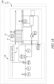
- a fuel cell system (e.g., a fuel cell apparatus) 10 often includes one or more fuel cell stacks 12 or fuel cell modules 14 connected to a balance of plant (BOP) 16, including various components, to create, generate, and/or distribute electrical power to meet modern day industrial and commercial needs in an environmentally friendly way.
- BOP balance of plant
- a fuel cell system 10 may include fuel cell stacks 12 including a plurality of individual fuel cells 20. Each fuel cell stack 12 may house a plurality of fuel cells 20 connected together in series and/or in parallel.
- the fuel cell system 10 may include one or more fuel cell modules 14 as shown in FIGS. 1A and 1B .
- Each fuel cell module 14 may include a plurality of fuel cell stacks 12 and/or a plurality of fuel cells 20.
- the fuel cell module 14 may also include a suitable combination of associated structural elements, mechanical systems, hardware, firmware, and/or software that is employed to support the function and operation of the fuel cell module 14.
- Such items include, without limitation, piping, sensors, regulators, current collectors, seals and insulators.
- the fuel cells 20 in the fuel cell stacks 12 may be stacked together to multiply and increase the voltage output of a single fuel cell stack 12.
- the number of fuel cell stacks 12 in a fuel cell system 10 can vary depending on the amount of power required to operate the fuel cell system 10 and meet the power need of any load.
- the number of fuel cells 20 in a fuel cell stack 12 can vary depending on the amount of power required to operate the fuel cell system 10 including the fuel cell stacks 12.
- the number of fuel cells 20 in each fuel cell stack 12 or fuel cell system 10 can be any number.
- the number of fuel cells 20 in each fuel cell stack 12 may range from about 100 fuel cells to about 1000 fuel cells, including any specific number or range of number of fuel cells 20 comprised therein (e.g., about 200 to about 800).
- the fuel cell system 10 may include about 20 to about 1000 fuel cells stacks 12, including any specific number or range of number of fuel cell stacks 12 comprised therein (e.g., about 200 to about 800).
- the fuel cells 20 in the fuel cell stacks 12 within the fuel cell module 14 may be oriented in any direction to optimize the operational efficiency and functionality of the fuel cell system 10.
- the fuel cells 20 in the fuel cell stacks 12 may be any type of fuel cell 20.
- the fuel cell 20 may be a polymer electrolyte membrane or proton exchange membrane (PEM) fuel cell, an anion exchange membrane fuel cell (AEMFC), an alkaline fuel cell (AFC), a molten carbonate fuel cell (MCFC), a direct methanol fuel cell (DMFC), a regenerative fuel cell (RFC), a phosphoric acid fuel cell (PAFC), or a solid oxide fuel cell (SOFC).
- the fuel cells 20 may be a polymer electrolyte membrane or proton exchange membrane (PEM) fuel cell or a solid oxide fuel cell (SOFC).
- the fuel cell stack 12 includes a plurality of proton exchange membrane (PEM) fuel cells 20.
- Each fuel cell 20 includes a single membrane electrode assembly (MEA) 22 and a gas diffusion layer (GDL) 24, 26 on either or both sides of the membrane electrode assembly (MEA) 22 (see FIG. 1C ).
- the fuel cell 20 further includes a bipolar plate (BPP) 28, 30 on the external side of each gas diffusion layers (GDL) 24, 26.
- BPP bipolar plate
- the above mentioned components, 22, 24, 26, 30 comprise a single repeating unit 50.
- the bipolar plates (BPP) 28, 30 are responsible for the transport of reactants, such as fuel 32 (e.g., hydrogen) or oxidant 34 (e.g., oxygen, air), and cooling fluid 36 (e.g., coolant and/or water) in a fuel cell 20.
- the bipolar plate (BPP) 28, 30 can uniformly distribute reactants 32, 34 to an active area 40 of each fuel cell 20 through oxidant flow fields 42 and/or fuel flow fields 44.
- the active area 40 where the electrochemical reactions occur to generate electrical power produced by the fuel cell 20, is centered within the gas diffusion layer (GDL) 24, 26 and the bipolar plate (BPP) 28, 30 at the membrane electrode assembly (MEA) 22.
- the bipolar plate (BPP) 28, 30 are compressed together to isolate and/or seal one or more reactants 32 within their respective pathways, channels, and/or flow fields 42, 44 to maintain electrical conductivity, which is required for robust during fuel cell 20 operation.
- the fuel cell system 10 described herein may be used in stationary and/or immovable power system, such as industrial applications and power generation plants.
- the fuel cell system 10 may also be implemented in conjunction with electrolyzers 18 and/or other electrolysis system 18.
- the fuel cell system 10 is connected and/or attached in series or parallel to an electrolysis system 18, such as one or more electrolyzers 18 in the BOP 16 (see FIG. 1A ).
- the fuel cell system 10 is not connected and/or attached in series or parallel to an electrolysis system 18, such as one or more electrolyzers 18 in the BOP 16.
- the present fuel cell system 10 may also be comprised in mobile applications.
- the fuel cell system 10 is in a vehicle and/or a powertrain 100.
- a vehicle 100 comprising the present fuel cell system 10 may be an automobile, a pass car, a bus, a truck, a train, a locomotive, an aircraft, a light duty vehicle, a medium duty vehicle, or a heavy duty vehicle.
- Type of vehicles 100 can also include, but are not limited to commercial vehicles and engines, trains, trolleys, trams, planes, buses, ships, boats, and other known vehicles, as well as other machinery and/or manufacturing devices, equipment, installations, among others.
- the vehicle and/or a powertrain 100 may be used on roadways, highways, railways, airways, and/or waterways.
- the vehicle 100 may be used in applications including but not limited to off highway transit, bobtails, and/or mining equipment.
- mining equipment vehicle 100 is a mining truck or a mine haul truck.
- the fuel cell system 10 is a hydrogen fuel cell system, such as a polymer electrolyte membrane or proton exchange membrane (PEM) fuel cell system, an alkaline fuel cell (AFC) system, a molten carbonate fuel cell (MCFC) system, a phosphoric acid fuel cell (PAFC) system, or a solid oxide fuel cell (SOFC) system.
- PEM polymer electrolyte membrane or proton exchange membrane
- AFC alkaline fuel cell
- MCFC molten carbonate fuel cell
- PAFC phosphoric acid fuel cell
- SOFC solid oxide fuel cell
- the fuel cell system may be any other type of fuel cell system that does not use diesel or gasoline as the fuel source.
- the hydrogen fuel cell system may be a PEM fuel cell system.
- the fuel cell system 10 comprises a ventilation system 112.
- the ventilation system 112 may have an air compressor 114, a fuel cell enclosure 116, and a network of hosing 118, which couples the air compressor 114 to the fuel cell enclosure 116.
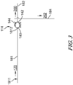
- the fuel cell system 10 operates when the air compressor 114 draws an air stream 120 into the ventilation system 112 directing the air stream 120 through the network of hosing 118 until the air stream 120 is expelled from the ventilation system 112, as depicted in FIG. 3 .
- the fuel cell enclosure 116 may house or include one or more fuel cells 20 and/or one or more fuel cell stacks 16.
- the air compressor 114 is configured to draw the air stream 120 into the system through an inlet 140, as can be seen in FIG. 3 .
- the air compressor 114 is further configured to compress the air stream 120 such that it becomes a compressed air stream 200.
- the air compressor 114 may then push the compressed air stream 200 out of a first outlet 142, of at least two outlets 142/144 of the air compressor 114, as is illustrated in FIG. 3 .
- a portion of the air stream 120 is siphoned from the compressed air stream 200.
- the siphoned air stream 120 may be vented from the air compressor 114 through a second outlet 144 of the at least two outlets 142/144 of the air compressor 114. That siphoned air 120 becomes a parasitic loss air stream 202, as shown in FIG. 3 .
- the air compressor 114 may have multiple air inlets 140. Additional inlets 140 may, for example, receive the parasitic loss air stream 202 as a recycled air stream (not shown) to ventilate the air compressor 114.
- the air compressor 114 may have multiple inlets 140 as part of an air compression system, such as an air compressor 114 that operates with two air compressor inlets 140.
- the air compressor 114 comprising two air compressor inlets 140 may be or comprise a two-stage reciprocating piston air compression system.
- the air compressor 114 comprising two air compressor inlets 140 may be or comprise a two-stage centrifugal compressor system (not shown).
- the fuel cell enclosure 116 houses a fuel cell 20 or a fuel cell stack 12 of the fuel cell system 10.
- the fuel cell stack 12 may comprise different types of fuel 32, including but not limited to hydrogen, ethanol, methane, and/or natural gas.
- the fuel 32 of the fuel cell system 10 is, comprises, consists essentially of, or consists of hydrogen.
- the fuel cell enclosure 116 may also comprise at least two fuel cell enclosure inlets 160/162. Yet in a further embodiment, the fuel cell enclosure 116 may comprise at least one fuel cell enclosure outlet 164, as shown in FIG 4 . In an exemplary embodiment, the fuel cell 116 comprises at least two fuel cell enclosure inlets 160/162 and at least one fuel cell enclosure outlet 164.
- the enclosure 116 of the ventilation system 112 receives the compressed air stream 200 through inlet 160 and the parasitic loss air stream 202 through inlet 162, as illustrated in FIGS. 4-6 .
- the compressed air stream 200 that enters the enclosure 116 is used by the fuel cell 20 or fuel cell stack 12 to create electricity.
- the parasitic loss air stream 202 that enters the enclosure 116 is used to ventilate the enclosure 116.
- the parasitic loss air stream 202 and any additional air within the enclosure 116 is vented from the outlet 164 of the enclosure 116 as an exhaust air stream 204.
- the exhaust air stream 204 is exhausted into the atmosphere.
- the enclosure 116 comprises additional inlets 160 to receive, for example, additional air for venting the enclosure 116.
- the enclosure 116 is configured with additional outlets 166/126, as shown in FIG. 4 .
- the additional outlets 164 may include a pressure relief valve 126, which may help remove the exhaust air stream 204 more quickly if or when the pressure in the fuel cell system 10 is too high.
- outlet 166 augments the normal operation of outlet 164, as a means to exhaust the enclosure exhaust air stream 204 from the ventilation system 112 into the atmosphere.
- the network of hosing 118 may comprise one or more, two or more, three or more, multiple, several, and/or a plurality of hose segments 181/182/183/184/185/186, as shown in FIGS. 2-6 .
- a first hose segment 181 has a first free end 1811 that permits the entrance of the air stream 120 into the ventilation system 112, as depicted in FIG. 2 .
- the first hose segment 181 is coupled to the inlet 140 of the compressor 114 at a second end 1812 (see FIG. 3 ).
- an air filter 122 is disposed along the first hose segment 181, as shown in FIGS. 5A, 5B , and 6 . In other embodiments, there is no air filter 122 comprised by the first hose segment 181. In further embodiments, there is no first hose segment 181 comprised by the ventilation system 112 of the fuel cell system 10.
- a second hose segment 182 and a third hose segment 183 cooperate to create a first flow path 130.
- the first flow path 130 is the travel path for the compressed air stream 200.
- the compressed air stream 200 travels from the air compressor 114 along the second hose segment 182 through the fuel cell enclosure 116.
- the compressed air further travels out of the fuel cell enclosure 116 of the ventilation system 112 along the third hose segment 183 on the first flow path 130.
- a first end 1821 of the second hose segment 182 is coupled to the outlet 142 of the air compressor 114 (see FIG. 5A ).
- a second end 1822 of the second hose segment 182 is coupled to the inlet 160 of the fuel cell enclosure 116.
- a first end 1831 of the third hose segment 183 is coupled to outlet 164 of the enclosure 116.
- a second end 1832 of the third hose segment 183 is free (see FIG. 5A ).
- Other embodiments of the first flow path 130 may comprise additional or different hose segments (not shown).
- the network of hosing 118 creates a second flow path having different embodiments 40/242/44.
- the second flow path 40/242/44 is the travel path for the parasitic loss air stream 202.
- parasitic loss air 202 in the second flow path 40/42/44 may travel from a second outlet 144 of the air compressor 114 through the fuel cell enclosure 116 and out of the ventilation system 112.
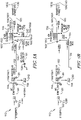
- One embodiment of the second flow path 240 comprises the third hose segment 183 and a fourth hose segment 184, as can be seen in FIG. 5B .
- a first end 1841 of the fourth hose segment 184 is coupled to the outlet 144 of the air compressor 114 (see FIG. 5B ) and a second end 1842 of the fourth hose segment 184 is coupled to inlet 162 of the fuel cell enclosure 116, as shown in FIG. 5B .
- a first end 1831 of the third hose segment 183 is coupled to outlet 164 of the enclosure 116 and a second end 1832 of the third hose segment 183 is free (see FIG. 5B ).
- FIG. 5A illustrates another embodiment of the second flow path 242.
- This embodiment of the second flow path 242 comprises the fourth hose segment 184 and a fifth hose segment 185, as can be seen in FIG. 5A .
- a first end 1841 of the fourth hose segment 184 is coupled to the outlet 144 of the air compressor 114, as shown in FIG. 5A and a second end 1842 of the fourth hose segment 184 is coupled to inlet 162 of the fuel cell enclosure 116, as shown in FIG. 5A .
- this embodiment of the second flow path 242 comprises a fifth hose segment 185.
- a first end 1851 of the fifth hose segment 185 is coupled to an outlet 166 of the fuel cell enclosure 116 and a second end 1852 of the fifth hose segment 185 is free.
- the ventilation system 112 comprises two outlets 164/166 from which to vent the fuel cell enclosure 116 exhaust air stream 204 to the environment or atmosphere.
- FIG. 6 Yet a further embodiment of the second flow path 244 is shown in FIG. 6 .
- This embodiment of the second flow path 244 may include the fourth hose segment 184, the fifth hose segment 185, and a sixth hose segment 186, as can be seen in FIG. 6 .
- a first end 1841 of the fourth hose segment 184 is coupled to the outlet 144 of the air compressor 114, as shown in FIG. 6 .
- the second end 1842 of the fourth hose segment 184 may be free or may be combined or connected to the third hose segment 183 in order to exhaust air stream from the fuel cell enclosure 116 to the environment or atmosphere (see FIG. 6 ).
- a first end 1861 of the sixth hose segment 186 is joined to the fourth hose segment 184.
- the first end 1861 of the sixth hose segment 186 is joined to the fourth hose segment 184 at an interior redirection point 1843 (see FIG. 6 ).
- a second end 1862 of the sixth hose segment may be coupled to the inlet 162 of the fuel cell enclosure 116.
- a first end 1851 of the fifth hose segment 185 may be coupled to outlet 166 of the enclosure 116 (see FIG. 6 ) while a second end 1852 of the fifth hose segment 185 may be joined to the fourth hose segment 184 at an interior return point 1844.
- Some embodiments of the second flow path do not comprise the fifth hose segment 185 (see FIG. 5A ).
- the redirection point 1843 is located down-flow or downstream of the first end 1841 of the fourth hose segment 184.
- the return point 1844 is located down-flow or downstream of the redirection point 1843.
- the second end 1842 of the fourth hose segment 184 is located down-flow or downstream of the return point 1844.
- the parasitic loss air stream 202 flows from the compressor 114 to and through the redirection point 1843. Then, the parasitic loss air stream 202 flows to the fuel cell enclosure 116 through the sixth hose segment 186.
- the enclosure exhaust air stream 204 flows from the fuel cell enclosure 116 through the fifth hose segment 185 back to the fourth hose segment 184 at the return point 1844.
- the enclosure exhaust air stream 204 is then vented from the ventilation system 112 at the second free end 1842 of the fourth hose segment 184.
- the second end 1842 of the fourth hose segment 184 vents the enclosure exhaust air stream 204 to the third hose segment 183 at an interior exhaust collection point 1833, as shown in FIG. 6 .
- the ventilation system 112 comprises two outlets 164/166 from which to vent the enclosure exhaust air stream.
- any number of additional flow paths such as a third flow path, a fourth flow path, and/or a fifth flow path (not shown) may be created and utilized to route the air streams 120 by the network of hosing 18.
- the additional flow paths may facilitate multiple fuel cell stacks 12 in multiple fuel cell enclosures 116 to work in series, allow multiple air compressors 114 to feed the fuel cell stacks 12, direct enclosure exhaust air streams 204 to vent at a particular location, capture and redirect or reuse gases inherent to the system, and/or permit any other use.
- air cooling devices 28/29 may be utilized to cool air stream 20/200/202 prior to it entering the fuel cell enclosure 116.
- the compressed air stream 200 of the present systems 10 and 11 may pass through a process air cooler 29 along the second hose segment 182, as shown in FIGS. 5A-6 .
- the compressed air stream is processed by the process air cooler 29 to create a processed air stream 206.
- the processed air stream 206 then enters the fuel cell enclosure 116 through inlet 160 (see FIGS. 5A-6 ).
- the parasitic loss air stream 202 passes through a ventilation air cooler 28.
- the parasitic loss air stream 202 passes through a ventilation air cooler 128 along the fourth hose segment 184 (see FIG. 5A ).
- parasitic loss air stream 202 passes through a ventilation air cooler 128 along the sixth hose segment 186 (see FIG. 6 ).
- the parasitic air stream 202 is cooled by the ventilation air cooler 128 to create a cooled ventilation air stream 208.
- the cooled ventilation air stream 208 then enters the fuel cell enclosure 116 through inlet 162 (see FIG. 6 ). Ventilating the enclosure 116 with the cooled ventilation air stream 208 versus the parasitic loss air stream 202 has advantages and benefits. Specifically, cooling the fuel cell enclosure 116 with the cooled ventilation air stream 208 may result in a reduction of temperature inside the fuel cell enclosure 116 ranging from about 5 degrees to about 20 degrees including all specific and range of temperatures comprised therein. This reduction in temperature can extend the life of the components and electronics of the fuel cell 124 and fuel cell system 10, thus increasing the lifespan, performance, and efficiency of the fuel cell system 10.
- the present disclosure is also directed to a method of ventilating the fuel cell enclosure 116.
- the present method of ventilating the fuel cell enclosure 116 comprises the steps of drawing an air stream 120 into the fuel cell system 10 through an air compressor 14.
- the air stream 120 may comprise a parasitic loss air stream 202 and an enclosure exhaust air stream 204.
- the present method of ventilating the fuel cell enclosure 116 may further comprise the steps of expelling the parasitic loss air stream 202 from the air compressor 114 into a network of hosing 18.
- the method also comprises directing the parasitic loss air stream 202 into a fuel cell enclosure 116 by the network of hosing 18.
- the method comprises venting the enclosure exhaust air stream 204 from the fuel cell enclosure 116.
- the parasitic loss air stream 202 passes through a ventilation air cooler 28.
- an exhausted air stream (not shown) may be recirculated into the system 10/112. The recirculated exhausted air stream may be utilized to vent the air bearings of the air compressor to create the parasitic loss air stream 202. Therefore, the parasitic loss air stream 202 may be an exhausted air stream used to vent the air bearings of the air compressor.
- a first aspect of the present invention relates to a system or apparatus for ventilating a fuel cell enclosure.
- the system includes a fuel cell enclosure, an air compressor, a network of hosing, and an air stream.
- the fuel cell enclosure includes at least two fuel cell enclosure inlets and at least one fuel cell enclosure outlet.
- the air compressor includes at least one air compressor inlet and at least two air compressor outlets.
- the air stream includes a compressed air stream and a parasitic loss air stream.
- the network of hosing includes at least four hose segments.
- a first hose segment of the first aspect includes a first free end and a second end coupled to the at least one air compressor inlet.
- a second hose segment includes a first end coupled to one of the at least two air compressor outlets and a second end coupled to one of the at least two fuel cell enclosure inlets.
- a third hose segment includes a first end coupled to the at least one fuel cell enclosure outlet and a second free end.
- a fourth hose segment includes a first end coupled to a second of the at least two air compressor outlets. The second hose segment and the third hose segment are included in a first flow path, and the fourth hose segment is included in a second flow path.
- a second aspect of the present invention relates to a method of ventilating a fuel cell enclosure of a fuel cell system.
- the method includes the steps of drawing an air stream into the fuel cell system through an air compressor, the air stream including a parasitic loss air stream and an enclosure exhaust air stream, expelling the parasitic loss air stream from the air compressor into a network of hosing, directing the parasitic loss air stream into the fuel cell enclosure by the network of hosing, and venting an enclosure exhaust air stream from the fuel cell enclosure.
- the fourth hose segment may further include a second end coupled to a second of the at least two fuel cell enclosure inlets.
- the second flow path may further include the third hose segment.
- the parasitic loss air stream may pass through a ventilation air cooler along the fourth hose segment.
- the network of hosing may further include a fifth hose segment.
- the fifth hose segment may include a first end coupled to a second of the at least one fuel cell enclosure outlet and a second free end.
- the fifth hose segment may be included in the second flow path.
- the parasitic loss air stream may pass through a ventilation air cooler along the fourth hose segment.
- the fuel cell enclosure may include a fuel cell or fuel cell stack.
- the fuel cell or the fuel cell stack may include hydrogen.
- the fourth hose segment may further include a second free end.
- the network of hosing may include a fifth hose segment and a sixth hose segment.
- the sixth hose segment may include a first end joined to the fourth hose segment at a redirection point and a second end coupled to a second of the at least two fuel cell enclosure inlets
- the fifth hose segment may include a first end coupled to a second of the at least one fuel cell enclosure outlet and a second end joined to the fourth hose segment at a return point.
- the second flow path includes the sixth and fifth hose segment and the return point may be located down-flow of the redirection point along the second flow path.
- the parasitic loss air stream may pass through a ventilation air cooler along the sixth hose segment.
- the fuel cell enclosure may include a fuel cell or a fuel cell stack.
- the fuel cell or fuel cell stack may include hydrogen.
- the at least one fuel cell enclosure outlet may include a pressure relief valve.
- an air filter may be disposed along the first hose segment.
- the first flow path may provide a travel path for the compressed air stream.
- the second flow path may provide a travel path for the parasitic loss air stream.
- the parasitic loss air stream may be an exhausted air stream used to vent the air bearings of the air compressor.
- expelling the parasitic loss air stream into the network of hosing may include passing parasitic loss air stream through a ventilation air cooler.
- venting the enclosure exhaust air stream from the fuel cell enclosure may include pushing the enclosure exhaust air stream through a network of hosing.
- the fuel cell enclosure may include a fuel cell or fuel cell stack.
- the fuel cell or the fuel cell stack may use hydrogen.
- the network of hosing may provide at least one flow path. The at least one flow path may provide a travel path for the parasitic loss air stream.
- the first flow path and/or the second flow path may provide a travel path for the parasitic loss air stream.
- embodiments “comprising,” “including,” or “having” an element or a plurality of elements having a particular property may include additional such elements not having that property.
- the term “comprising” or “comprises” refers to a composition, compound, formulation, or method that is inclusive and does not exclude additional elements, components, and/or method steps.
- the term “comprising” also refers to a composition, compound, formulation, or method embodiment of the present disclosure that is inclusive and does not exclude additional elements, components, or method steps.
- the phrase “consisting of' or “consists of' refers to a compound, composition, formulation, or method that excludes the presence of any additional elements, components, or method steps.
- Consisting of' also refers to a compound, composition, formulation, or method of the present disclosure that excludes the presence of any additional elements, components, or method steps.
- the phrase “consisting essentially of' or “consists essentially of' refers to a composition, compound, formulation, or method that is inclusive of additional elements, components, or method steps that do not materially affect the characteristic(s) of the composition, compound, formulation, or method.
- the phrase “consisting essentially of' also refers to a composition, compound, formulation, or method of the present disclosure that is inclusive of additional elements, components, or method steps that do not materially affect the characteristic(s) of the composition, compound, formulation, or method steps.
- Approximating language may be applied to modify any quantitative representation that could permissibly vary without resulting in a change in the basic function to which it is related. Accordingly, a value modified by a term or terms, such as "about,” and “substantially” is not to be limited to the precise value specified. In some instances, the approximating language may correspond to the precision of an instrument for measuring the value.
- range limitations may be combined and/or interchanged. Such ranges are identified and include all the sub-ranges contained therein unless context or language indicates otherwise.
- the terms “may” and “may be” indicate a possibility of an occurrence within a set of circumstances; a possession of a specified property, characteristic or function; and/or qualify another verb by expressing one or more of an ability, capability, or possibility associated with the qualified verb. Accordingly, usage of "may” and “may be” indicates that a modified term is apparently appropriate, capable, or suitable for an indicated capacity, function, or usage, while taking into account that in some circumstances, the modified term may sometimes not be appropriate, capable, or suitable.
Landscapes
- Engineering & Computer Science (AREA)
- Chemical & Material Sciences (AREA)
- Life Sciences & Earth Sciences (AREA)
- Manufacturing & Machinery (AREA)
- Sustainable Development (AREA)
- Sustainable Energy (AREA)
- Chemical Kinetics & Catalysis (AREA)
- Electrochemistry (AREA)
- General Chemical & Material Sciences (AREA)
- Combustion & Propulsion (AREA)
- Fuel Cell (AREA)
Applications Claiming Priority (1)
| Application Number | Priority Date | Filing Date | Title |
|---|---|---|---|
| US202163236529P | 2021-08-24 | 2021-08-24 |
Publications (2)
| Publication Number | Publication Date |
|---|---|
| EP4142000A1 true EP4142000A1 (de) | 2023-03-01 |
| EP4142000B1 EP4142000B1 (de) | 2026-04-29 |
Family
ID=83005866
Family Applications (1)
| Application Number | Title | Priority Date | Filing Date |
|---|---|---|---|
| EP22191494.8A Active EP4142000B1 (de) | 2021-08-24 | 2022-08-22 | Systeme und verfahren zur belüftung eines brennstoffzellengehäuses |
Country Status (4)
| Country | Link |
|---|---|
| US (1) | US12438165B2 (de) |
| EP (1) | EP4142000B1 (de) |
| CN (1) | CN115719823A (de) |
| CA (1) | CA3170862C (de) |
Families Citing this family (1)
| Publication number | Priority date | Publication date | Assignee | Title |
|---|---|---|---|---|
| WO2026039428A1 (en) * | 2024-08-13 | 2026-02-19 | Joby Aero, Inc. | Pressurized fuel cell system |
Citations (3)
| Publication number | Priority date | Publication date | Assignee | Title |
|---|---|---|---|---|
| DE102019209210A1 (de) * | 2019-06-26 | 2020-12-31 | Robert Bosch Gmbh | Brennstoffzellensystem mit einer Belüftungsleitung und/oder einer Verdichterbelüftungsleitung, Verfahren zum Belüften eines Gehäuses eines Brennstoffzellensytems sowie Kraftfahrzeug |
| US20210066732A1 (en) * | 2018-01-17 | 2021-03-04 | Audi Ag | Fuel cell system having a medium pressure tap associated with the compressor and use of such a fuel cell system |
| CN113013444A (zh) * | 2021-02-09 | 2021-06-22 | 广西玉柴机器股份有限公司 | 一种燃料电池系统集成氢气吹扫装置和尾排稀释功能的空气子系统及其控制方法 |
Family Cites Families (8)
| Publication number | Priority date | Publication date | Assignee | Title |
|---|---|---|---|---|
| DE69923550T2 (de) * | 1998-04-08 | 2006-02-16 | Shionogi & Co., Ltd. | Verfahren um Vorläuferzellen von Osteoklasten zu isolieren und ihre Differenzierung in Osteoklasten zu induzieren. |
| US6610431B1 (en) | 2000-02-11 | 2003-08-26 | Plug Power Inc. | Method and apparatus for establishing a negative pressure inside an enclosure that houses a fuel cell system |
| US8486575B2 (en) | 2004-02-05 | 2013-07-16 | GM Global Technology Operations LLC | Passive hydrogen vent for a fuel cell |
| US9947945B2 (en) | 2008-01-25 | 2018-04-17 | Ford Global Technologies, Llc | Ventilation system for an automotive fuel cell stack enclosure |
| FR2973953A1 (fr) * | 2011-04-05 | 2012-10-12 | Commissariat Energie Atomique | Pile a combustible a encombrement reduit |
| US20190109331A1 (en) | 2017-10-09 | 2019-04-11 | GM Global Technology Operations LLC | Fuel cell system with improved ventilation |
| JP2021501966A (ja) | 2017-11-03 | 2021-01-21 | ヌヴェラ・フュエル・セルズ,エルエルシー | 漏れ回収能を備えた燃料電池モジュールのアレンジメントおよび使用方法 |
| CN211829050U (zh) | 2020-03-25 | 2020-10-30 | 北京亿华通科技股份有限公司 | 通风系统及燃料电池箱体的通风系统 |
-
2022
- 2022-08-15 US US17/888,201 patent/US12438165B2/en active Active
- 2022-08-19 CA CA3170862A patent/CA3170862C/en active Active
- 2022-08-22 EP EP22191494.8A patent/EP4142000B1/de active Active
- 2022-08-23 CN CN202211013592.1A patent/CN115719823A/zh active Pending
Patent Citations (3)
| Publication number | Priority date | Publication date | Assignee | Title |
|---|---|---|---|---|
| US20210066732A1 (en) * | 2018-01-17 | 2021-03-04 | Audi Ag | Fuel cell system having a medium pressure tap associated with the compressor and use of such a fuel cell system |
| DE102019209210A1 (de) * | 2019-06-26 | 2020-12-31 | Robert Bosch Gmbh | Brennstoffzellensystem mit einer Belüftungsleitung und/oder einer Verdichterbelüftungsleitung, Verfahren zum Belüften eines Gehäuses eines Brennstoffzellensytems sowie Kraftfahrzeug |
| CN113013444A (zh) * | 2021-02-09 | 2021-06-22 | 广西玉柴机器股份有限公司 | 一种燃料电池系统集成氢气吹扫装置和尾排稀释功能的空气子系统及其控制方法 |
Also Published As
| Publication number | Publication date |
|---|---|
| EP4142000B1 (de) | 2026-04-29 |
| US20230062150A1 (en) | 2023-03-02 |
| CA3170862A1 (en) | 2023-02-24 |
| CA3170862C (en) | 2025-03-25 |
| CN115719823A (zh) | 2023-02-28 |
| US12438165B2 (en) | 2025-10-07 |
Similar Documents
| Publication | Publication Date | Title |
|---|---|---|
| US12374696B2 (en) | Integrated fuel cell and combustion system | |
| US10483563B2 (en) | Cathode supply for a fuel cell | |
| US20170092964A1 (en) | Fuel cell module including heat exchanger and method of operating such module | |
| US12438165B2 (en) | Systems and methods for ventilating a fuel cell enclosure | |
| US20230178765A1 (en) | Fuel cell stack humidification system | |
| US20240006628A1 (en) | Unit cell architecture for water management in a fuel cell | |
| EP4290628A2 (de) | Systeme und verfahren zur leckdetektion eines wasserstoffzufuhrventils | |
| US11165078B2 (en) | Generator unit having a fuel cell device, vehicle having a generator unit of this type and method for monitoring a generator unit | |
| KR102764259B1 (ko) | 연료전지 스택 | |
| US20230246210A1 (en) | Systems and methods to optimize a fuel recirculation loop in a fuel cell stack | |
| EP4297221A1 (de) | Dynamische steuerung von parallel geschalteten brennstoffzellensystemen | |
| US20230387435A1 (en) | Multiple fuel cell stacks in a single endplate arrangement | |
| EP4535468A1 (de) | Brennstoffzellenwärmemanagementsystem mit gebogener knieförmiger radiatoranordnung und verfahren zur verwendung davon | |
| CN117889090A (zh) | 氢气再循环泵加热和密封组件与方法 | |
| US20250183332A1 (en) | Fuel cell stack current collector | |
| US12500251B2 (en) | Systems and methods for liquid heating balance of plant components of a fuel cell module | |
| DE102013207105A1 (de) | Brennstoffzellensystem zum Erwärmen einer Brennstoffzelle und Verfahren zum Betreiben eines Brennstoffzellensystems | |
| US20230402617A1 (en) | Hybrid bipolar plate for a fuel cell and methods of manufacturing the same | |
| US20250293274A1 (en) | Framing assembly for an electrochemical cell and method of using the same | |
| US20250112251A1 (en) | Systems and methods for reducing damage on a metal plate stack | |
| EP4685885A1 (de) | Integrierte membrananordnung für eine elektrochemische zelle und verfahren zu ihrer herstellung | |
| EP4632108A1 (de) | Gasverwaltungssystem für eine elektrochemische zelle | |
| CN217822882U (zh) | 用于提高燃料电池系统效率的中间冷却器架构 | |
| US20250201866A1 (en) | Bipolar plate alignment system and method of using the same | |
| CN220474671U (zh) | 用于管理燃料电池系统运行的集成歧管和燃料电池系统 |
Legal Events
| Date | Code | Title | Description |
|---|---|---|---|
| PUAI | Public reference made under article 153(3) epc to a published international application that has entered the european phase |
Free format text: ORIGINAL CODE: 0009012 |
|
| STAA | Information on the status of an ep patent application or granted ep patent |
Free format text: STATUS: THE APPLICATION HAS BEEN PUBLISHED |
|
| AK | Designated contracting states |
Kind code of ref document: A1 Designated state(s): AL AT BE BG CH CY CZ DE DK EE ES FI FR GB GR HR HU IE IS IT LI LT LU LV MC MK MT NL NO PL PT RO RS SE SI SK SM TR |
|
| P01 | Opt-out of the competence of the unified patent court (upc) registered |
Effective date: 20230510 |
|
| STAA | Information on the status of an ep patent application or granted ep patent |
Free format text: STATUS: REQUEST FOR EXAMINATION WAS MADE |
|
| 17P | Request for examination filed |
Effective date: 20230831 |
|
| RBV | Designated contracting states (corrected) |
Designated state(s): AL AT BE BG CH CY CZ DE DK EE ES FI FR GB GR HR HU IE IS IT LI LT LU LV MC MK MT NL NO PL PT RO RS SE SI SK SM TR |
|
| STAA | Information on the status of an ep patent application or granted ep patent |
Free format text: STATUS: EXAMINATION IS IN PROGRESS |
|
| 17Q | First examination report despatched |
Effective date: 20240612 |
|
| GRAP | Despatch of communication of intention to grant a patent |
Free format text: ORIGINAL CODE: EPIDOSNIGR1 |
|
| STAA | Information on the status of an ep patent application or granted ep patent |
Free format text: STATUS: GRANT OF PATENT IS INTENDED |
|
| INTG | Intention to grant announced |
Effective date: 20251121 |
|
| RIN1 | Information on inventor provided before grant (corrected) |
Inventor name: RIZZI, JUSTIN Inventor name: FORTE, PAOLO |
|
| GRAS | Grant fee paid |
Free format text: ORIGINAL CODE: EPIDOSNIGR3 |
|
| GRAA | (expected) grant |
Free format text: ORIGINAL CODE: 0009210 |
|
| STAA | Information on the status of an ep patent application or granted ep patent |
Free format text: STATUS: THE PATENT HAS BEEN GRANTED |