EP4141904A1 - Battery disconnect unit - Google Patents
Battery disconnect unit Download PDFInfo
- Publication number
- EP4141904A1 EP4141904A1 EP21883170.9A EP21883170A EP4141904A1 EP 4141904 A1 EP4141904 A1 EP 4141904A1 EP 21883170 A EP21883170 A EP 21883170A EP 4141904 A1 EP4141904 A1 EP 4141904A1
- Authority
- EP
- European Patent Office
- Prior art keywords
- electronic relay
- battery
- disconnect unit
- cover
- heat dissipation
- Prior art date
- Legal status (The legal status is an assumption and is not a legal conclusion. Google has not performed a legal analysis and makes no representation as to the accuracy of the status listed.)
- Pending
Links
- 230000017525 heat dissipation Effects 0.000 claims abstract description 46
- 238000001816 cooling Methods 0.000 claims abstract description 43
- 239000003507 refrigerant Substances 0.000 claims abstract description 24
- 239000000463 material Substances 0.000 claims abstract description 10
- 230000000903 blocking effect Effects 0.000 claims abstract description 3
- 230000005669 field effect Effects 0.000 claims description 4
- 239000004065 semiconductor Substances 0.000 claims description 4
- 229910044991 metal oxide Inorganic materials 0.000 claims description 3
- 150000004706 metal oxides Chemical class 0.000 claims description 3
- 230000000694 effects Effects 0.000 description 5
- 229910052751 metal Inorganic materials 0.000 description 4
- 239000002184 metal Substances 0.000 description 4
- 238000003466 welding Methods 0.000 description 4
- 239000003990 capacitor Substances 0.000 description 3
- OKTJSMMVPCPJKN-UHFFFAOYSA-N Carbon Chemical compound [C] OKTJSMMVPCPJKN-UHFFFAOYSA-N 0.000 description 2
- 238000012986 modification Methods 0.000 description 2
- 230000004048 modification Effects 0.000 description 2
- 239000000853 adhesive Substances 0.000 description 1
- 230000001070 adhesive effect Effects 0.000 description 1
- 229910052782 aluminium Inorganic materials 0.000 description 1
- XAGFODPZIPBFFR-UHFFFAOYSA-N aluminium Chemical compound [Al] XAGFODPZIPBFFR-UHFFFAOYSA-N 0.000 description 1
- 239000002041 carbon nanotube Substances 0.000 description 1
- 229910021393 carbon nanotube Inorganic materials 0.000 description 1
- 239000000498 cooling water Substances 0.000 description 1
- 230000007797 corrosion Effects 0.000 description 1
- 238000005260 corrosion Methods 0.000 description 1
- 230000007423 decrease Effects 0.000 description 1
- 238000010586 diagram Methods 0.000 description 1
- 238000007599 discharging Methods 0.000 description 1
- 230000005611 electricity Effects 0.000 description 1
- 230000005284 excitation Effects 0.000 description 1
- 229910002804 graphite Inorganic materials 0.000 description 1
- 239000010439 graphite Substances 0.000 description 1
- 239000004519 grease Substances 0.000 description 1
- 230000020169 heat generation Effects 0.000 description 1
- 238000001746 injection moulding Methods 0.000 description 1
- 230000002427 irreversible effect Effects 0.000 description 1
- 239000007788 liquid Substances 0.000 description 1
- 230000007257 malfunction Effects 0.000 description 1
- 239000000088 plastic resin Substances 0.000 description 1
- 238000000926 separation method Methods 0.000 description 1
- 229920002050 silicone resin Polymers 0.000 description 1
- 239000000243 solution Substances 0.000 description 1
- 230000003746 surface roughness Effects 0.000 description 1
Images


Classifications
-
- H—ELECTRICITY
- H05—ELECTRIC TECHNIQUES NOT OTHERWISE PROVIDED FOR
- H05K—PRINTED CIRCUITS; CASINGS OR CONSTRUCTIONAL DETAILS OF ELECTRIC APPARATUS; MANUFACTURE OF ASSEMBLAGES OF ELECTRICAL COMPONENTS
- H05K7/00—Constructional details common to different types of electric apparatus
- H05K7/20—Modifications to facilitate cooling, ventilating, or heating
- H05K7/2089—Modifications to facilitate cooling, ventilating, or heating for power electronics, e.g. for inverters for controlling motor
- H05K7/20927—Liquid coolant without phase change
-
- H—ELECTRICITY
- H01—ELECTRIC ELEMENTS
- H01M—PROCESSES OR MEANS, e.g. BATTERIES, FOR THE DIRECT CONVERSION OF CHEMICAL ENERGY INTO ELECTRICAL ENERGY
- H01M50/00—Constructional details or processes of manufacture of the non-active parts of electrochemical cells other than fuel cells, e.g. hybrid cells
- H01M50/20—Mountings; Secondary casings or frames; Racks, modules or packs; Suspension devices; Shock absorbers; Transport or carrying devices; Holders
- H01M50/204—Racks, modules or packs for multiple batteries or multiple cells
-
- H—ELECTRICITY
- H01—ELECTRIC ELEMENTS
- H01H—ELECTRIC SWITCHES; RELAYS; SELECTORS; EMERGENCY PROTECTIVE DEVICES
- H01H50/00—Details of electromagnetic relays
- H01H50/12—Ventilating; Cooling; Heating
-
- H—ELECTRICITY
- H01—ELECTRIC ELEMENTS
- H01L—SEMICONDUCTOR DEVICES NOT COVERED BY CLASS H10
- H01L23/00—Details of semiconductor or other solid state devices
- H01L23/34—Arrangements for cooling, heating, ventilating or temperature compensation ; Temperature sensing arrangements
- H01L23/40—Mountings or securing means for detachable cooling or heating arrangements ; fixed by friction, plugs or springs
- H01L23/4006—Mountings or securing means for detachable cooling or heating arrangements ; fixed by friction, plugs or springs with bolts or screws
-
- H—ELECTRICITY
- H01—ELECTRIC ELEMENTS
- H01L—SEMICONDUCTOR DEVICES NOT COVERED BY CLASS H10
- H01L25/00—Assemblies consisting of a plurality of individual semiconductor or other solid state devices ; Multistep manufacturing processes thereof
- H01L25/03—Assemblies consisting of a plurality of individual semiconductor or other solid state devices ; Multistep manufacturing processes thereof all the devices being of a type provided for in the same subgroup of groups H01L27/00 - H01L33/00, or in a single subclass of H10K, H10N, e.g. assemblies of rectifier diodes
- H01L25/10—Assemblies consisting of a plurality of individual semiconductor or other solid state devices ; Multistep manufacturing processes thereof all the devices being of a type provided for in the same subgroup of groups H01L27/00 - H01L33/00, or in a single subclass of H10K, H10N, e.g. assemblies of rectifier diodes the devices having separate containers
- H01L25/11—Assemblies consisting of a plurality of individual semiconductor or other solid state devices ; Multistep manufacturing processes thereof all the devices being of a type provided for in the same subgroup of groups H01L27/00 - H01L33/00, or in a single subclass of H10K, H10N, e.g. assemblies of rectifier diodes the devices having separate containers the devices being of a type provided for in group H01L29/00
- H01L25/115—Assemblies consisting of a plurality of individual semiconductor or other solid state devices ; Multistep manufacturing processes thereof all the devices being of a type provided for in the same subgroup of groups H01L27/00 - H01L33/00, or in a single subclass of H10K, H10N, e.g. assemblies of rectifier diodes the devices having separate containers the devices being of a type provided for in group H01L29/00 the devices being arranged next to each other
-
- H—ELECTRICITY
- H01—ELECTRIC ELEMENTS
- H01M—PROCESSES OR MEANS, e.g. BATTERIES, FOR THE DIRECT CONVERSION OF CHEMICAL ENERGY INTO ELECTRICAL ENERGY
- H01M50/00—Constructional details or processes of manufacture of the non-active parts of electrochemical cells other than fuel cells, e.g. hybrid cells
- H01M50/10—Primary casings, jackets or wrappings of a single cell or a single battery
- H01M50/14—Primary casings, jackets or wrappings of a single cell or a single battery for protecting against damage caused by external factors
- H01M50/143—Fireproof; Explosion-proof
-
- H—ELECTRICITY
- H01—ELECTRIC ELEMENTS
- H01M—PROCESSES OR MEANS, e.g. BATTERIES, FOR THE DIRECT CONVERSION OF CHEMICAL ENERGY INTO ELECTRICAL ENERGY
- H01M50/00—Constructional details or processes of manufacture of the non-active parts of electrochemical cells other than fuel cells, e.g. hybrid cells
- H01M50/20—Mountings; Secondary casings or frames; Racks, modules or packs; Suspension devices; Shock absorbers; Transport or carrying devices; Holders
- H01M50/249—Mountings; Secondary casings or frames; Racks, modules or packs; Suspension devices; Shock absorbers; Transport or carrying devices; Holders specially adapted for aircraft or vehicles, e.g. cars or trains
-
- H—ELECTRICITY
- H01—ELECTRIC ELEMENTS
- H01M—PROCESSES OR MEANS, e.g. BATTERIES, FOR THE DIRECT CONVERSION OF CHEMICAL ENERGY INTO ELECTRICAL ENERGY
- H01M50/00—Constructional details or processes of manufacture of the non-active parts of electrochemical cells other than fuel cells, e.g. hybrid cells
- H01M50/20—Mountings; Secondary casings or frames; Racks, modules or packs; Suspension devices; Shock absorbers; Transport or carrying devices; Holders
- H01M50/271—Lids or covers for the racks or secondary casings
-
- H—ELECTRICITY
- H01—ELECTRIC ELEMENTS
- H01M—PROCESSES OR MEANS, e.g. BATTERIES, FOR THE DIRECT CONVERSION OF CHEMICAL ENERGY INTO ELECTRICAL ENERGY
- H01M50/00—Constructional details or processes of manufacture of the non-active parts of electrochemical cells other than fuel cells, e.g. hybrid cells
- H01M50/20—Mountings; Secondary casings or frames; Racks, modules or packs; Suspension devices; Shock absorbers; Transport or carrying devices; Holders
- H01M50/284—Mountings; Secondary casings or frames; Racks, modules or packs; Suspension devices; Shock absorbers; Transport or carrying devices; Holders with incorporated circuit boards, e.g. printed circuit boards [PCB]
- H01M50/287—Fixing of circuit boards to lids or covers
-
- H—ELECTRICITY
- H01—ELECTRIC ELEMENTS
- H01M—PROCESSES OR MEANS, e.g. BATTERIES, FOR THE DIRECT CONVERSION OF CHEMICAL ENERGY INTO ELECTRICAL ENERGY
- H01M50/00—Constructional details or processes of manufacture of the non-active parts of electrochemical cells other than fuel cells, e.g. hybrid cells
- H01M50/50—Current conducting connections for cells or batteries
- H01M50/572—Means for preventing undesired use or discharge
- H01M50/574—Devices or arrangements for the interruption of current
- H01M50/583—Devices or arrangements for the interruption of current in response to current, e.g. fuses
-
- H—ELECTRICITY
- H05—ELECTRIC TECHNIQUES NOT OTHERWISE PROVIDED FOR
- H05K—PRINTED CIRCUITS; CASINGS OR CONSTRUCTIONAL DETAILS OF ELECTRIC APPARATUS; MANUFACTURE OF ASSEMBLAGES OF ELECTRICAL COMPONENTS
- H05K7/00—Constructional details common to different types of electric apparatus
- H05K7/20—Modifications to facilitate cooling, ventilating, or heating
- H05K7/20218—Modifications to facilitate cooling, ventilating, or heating using a liquid coolant without phase change in electronic enclosures
- H05K7/20254—Cold plates transferring heat from heat source to coolant
-
- H—ELECTRICITY
- H01—ELECTRIC ELEMENTS
- H01H—ELECTRIC SWITCHES; RELAYS; SELECTORS; EMERGENCY PROTECTIVE DEVICES
- H01H2231/00—Applications
- H01H2231/026—Car
-
- H—ELECTRICITY
- H01—ELECTRIC ELEMENTS
- H01L—SEMICONDUCTOR DEVICES NOT COVERED BY CLASS H10
- H01L23/00—Details of semiconductor or other solid state devices
- H01L23/34—Arrangements for cooling, heating, ventilating or temperature compensation ; Temperature sensing arrangements
- H01L23/40—Mountings or securing means for detachable cooling or heating arrangements ; fixed by friction, plugs or springs
- H01L23/4006—Mountings or securing means for detachable cooling or heating arrangements ; fixed by friction, plugs or springs with bolts or screws
- H01L2023/4018—Mountings or securing means for detachable cooling or heating arrangements ; fixed by friction, plugs or springs with bolts or screws characterised by the type of device to be heated or cooled
- H01L2023/4031—Packaged discrete devices, e.g. to-3 housings, diodes
-
- H—ELECTRICITY
- H01—ELECTRIC ELEMENTS
- H01L—SEMICONDUCTOR DEVICES NOT COVERED BY CLASS H10
- H01L23/00—Details of semiconductor or other solid state devices
- H01L23/34—Arrangements for cooling, heating, ventilating or temperature compensation ; Temperature sensing arrangements
- H01L23/40—Mountings or securing means for detachable cooling or heating arrangements ; fixed by friction, plugs or springs
- H01L23/4006—Mountings or securing means for detachable cooling or heating arrangements ; fixed by friction, plugs or springs with bolts or screws
- H01L2023/4075—Mechanical elements
- H01L2023/4087—Mounting accessories, interposers, clamping or screwing parts
-
- H—ELECTRICITY
- H01—ELECTRIC ELEMENTS
- H01M—PROCESSES OR MEANS, e.g. BATTERIES, FOR THE DIRECT CONVERSION OF CHEMICAL ENERGY INTO ELECTRICAL ENERGY
- H01M2200/00—Safety devices for primary or secondary batteries
-
- H—ELECTRICITY
- H01—ELECTRIC ELEMENTS
- H01M—PROCESSES OR MEANS, e.g. BATTERIES, FOR THE DIRECT CONVERSION OF CHEMICAL ENERGY INTO ELECTRICAL ENERGY
- H01M2220/00—Batteries for particular applications
- H01M2220/20—Batteries in motive systems, e.g. vehicle, ship, plane
-
- Y—GENERAL TAGGING OF NEW TECHNOLOGICAL DEVELOPMENTS; GENERAL TAGGING OF CROSS-SECTIONAL TECHNOLOGIES SPANNING OVER SEVERAL SECTIONS OF THE IPC; TECHNICAL SUBJECTS COVERED BY FORMER USPC CROSS-REFERENCE ART COLLECTIONS [XRACs] AND DIGESTS
- Y02—TECHNOLOGIES OR APPLICATIONS FOR MITIGATION OR ADAPTATION AGAINST CLIMATE CHANGE
- Y02E—REDUCTION OF GREENHOUSE GAS [GHG] EMISSIONS, RELATED TO ENERGY GENERATION, TRANSMISSION OR DISTRIBUTION
- Y02E60/00—Enabling technologies; Technologies with a potential or indirect contribution to GHG emissions mitigation
- Y02E60/10—Energy storage using batteries
Landscapes
- Engineering & Computer Science (AREA)
- Microelectronics & Electronic Packaging (AREA)
- Chemical & Material Sciences (AREA)
- Chemical Kinetics & Catalysis (AREA)
- Electrochemistry (AREA)
- General Chemical & Material Sciences (AREA)
- Physics & Mathematics (AREA)
- Power Engineering (AREA)
- Computer Hardware Design (AREA)
- Condensed Matter Physics & Semiconductors (AREA)
- General Physics & Mathematics (AREA)
- Thermal Sciences (AREA)
- Electromagnetism (AREA)
- Aviation & Aerospace Engineering (AREA)
- Battery Mounting, Suspending (AREA)
- Secondary Cells (AREA)
- Cooling Or The Like Of Semiconductors Or Solid State Devices (AREA)
- Electric Propulsion And Braking For Vehicles (AREA)
Abstract
Description
- The present disclosure relates to a battery disconnect unit, and more particularly, to a battery disconnect unit designed to use an electronic relay module without a risk of contact welding and to properly manage the temperature of the electronic relay module.
- The present application claims priority to
Korean Patent Application No. 10-2020-0136057 filed on October 20, 2020 - In electric vehicles (EVs), hybrid vehicles (HVs), and the like, large-capacity battery packs are mounted to supply electricity for driving.
- A battery pack is connected to a load or a charger through a battery disconnect unit. The load refers to a device that receives power from a battery pack, such as a motor or inverter.
- As shown in
FIG. 1 , the battery disconnect unit includes a highpotential relay 10 installed on a line that connects a positive electrode terminal of a battery pack B to a positive electrode terminal of the load L, and a lowpotential relay 20 installed on a line that connects a negative electrode terminal of the battery pack B to a negative electrode terminal of the load L. - When the battery pack B is electrically connected to the load L, a large voltage of the battery pack B is abruptly applied to the load L, and thus an inrush current initially flows toward the load L. The rush current may cause irreversible damage by applying an electric shock to the load L.
- Thus, the battery disconnect unit includes an RC circuit including a
pre-charge resistor 40 and acapacitor 50, and apre-charge relay 30 connected to the highpotential relay 10 in parallel, - When the battery pack B and the load L intend to be electrically connected to each other, the low
potential relay 20 and thepre-charge relay 30 are primarily turned on. Then, a current output from the battery pack B flows to thecapacitor 50 through the RC circuit, and the magnitude of the current flowing through thecapacitor 50 gradually decreases as time increases. - When the
pre-charge relay 30 is turned on and the magnitude of the current reaches a pre-charge target voltage that does not impact the load L, the highpotential relay 10 is secondarily turned on, and then thepre-charge relay 30 is turned off, thereby completing electrical connection between the battery pack B and the load L. - Electro-mechanical relays that control interruption of metal contacts by using the excitation force of a magnetic coil and the restoration force of a spring have been widely applied as a high potential relay, a low potential relay, and a pre-charge relay.
- However, in the electro-mechanical relays, malfunction may occur due to spring failure and contact corrosion, and contact damage or contact welding may occur whenever a high current is opened or closed. In addition, the electro-mechanical relays consumes a lot of power, generate much heat, have high failure rates and large sizes, are heavy because of most component parts made of metal, and are relatively expensive.
- Because of these shortcomings of the electro-mechanical relays, electronic relays that supply or block power by using an electronic device such as an insulated gate bipolar transistor (IGBT) or a field effect transistor (FET) have recently been used as an alternative to the electro-mechanical relays. However, even in the case of electronic relays, when heat generation of the electronic device due to high current supply is not properly managed, the electronic device may be damaged, and thus a cooling device for electronic relays is needed. It is not easy to effectively configure the cooling device.
- The present disclosure is designed to solve the problems of the related art, and therefore the present disclosure is directed to providing a battery disconnect unit including a cooling device for effectively cooling an electronic relay, as a battery disconnect unit using an electronic relay.
- The technical problems to be solved in the present disclosure are not limited to the above, and other problems that are not mentioned could be clearly understood by one of ordinary skill in the art from the description of the present disclosure below.
- In one aspect of the present disclosure, there is provided a battery disconnect unit including: a BDU housing; an electronic relay module installed on a charge/discharge line of a battery within the BDU housing and including electronic switch devices capable of a switching operation of selectively blocking the flow of a current in the charge/discharge line; a heat dissipation cover provided with a structure surrounding at least a portion of the electronic relay module and formed of a material capable of heat exchange with the electronic relay module; and a cooling plate disposed in contact with the heat dissipation cover and provided to allow a refrigerant to flow in the cooling plate.
- The electronic relay module may include a first electronic relay installed on a line that connects a positive electrode terminal of the battery to a positive electrode terminal of an external device; a second electronic relay installed on a line that connects a negative electrode terminal of the battery to a negative electrode terminal of the external device; anda gate driver connected to the first electronic relay and the second electronic relay and configured to control a switching operation of the electronic switch device.
- The gate driver may be implemented as a printed circuit board, and a plate surface of the gate driver may be disposed perpendicular to the first electronic relay or the second electronic relay.
- The heat dissipation cover may include an upper cover and a lower cover provided to be coupled to each other. The lower cover may be provided in the form of a block including three first protrusions on both edges and a center region of the lower cover, respectively, and two first accommodating grooves concavely formed on both sides of the first protrusion located on the center region. The upper cover may be provided in the form of a block including three second protrusions and two second accommodating grooves corresponding to the three first protrusions and the two first accommodating grooves of the lower cover in a vertical direction. The first electronic relay and the second electronic relay may be respectively constrained in spaces formed by the two first accommodating grooves and the two second accommodating grooves, respectively.
- First heat transfer pads may be provided on surfaces of the first accommodating grooves and surfaces of the second accommodating grooves.
- A thermal interface material (TIM) may be provided between a lower surface of the lower cover and the cooling plate.
- The upper cover may have an upper surface having a convex-concave pattern structure.
- Each of the electronic switch devices may be an insulated gate bipolar transistor (IGBT) or a metal oxide semiconductor field effect transistor (MOSFET).
- The BDU housing may include a lower housing and an top cover provided to be coupled to each other. The heat dissipation cover may be fixedly disposed above the lower housing, the cooling plate may be fixedly disposed below the lower housing, and a portion of the lower housing below the heat dissipation cover may be open so that the heat dissipation cover and the cooling plate contact each other.
- The battery disconnect unit may further include a refrigerant supply pipe connected to one side of the cooling plate and a refrigerant discharge pipe connected to another side of the cooling plate.
- In another aspect of the present disclosure, there is provided a battery pack including the above-described battery disconnect unit.
- In another aspect of the present disclosure, there is provided an electric vehicle including the above-described battery pack.
- According to an aspect of the present disclosure, a battery disconnect unit including a cooling device for effectively cooling an electronic relay may be provided as a battery disconnect unit using an electronic relay.
- A battery disconnect unit according to the present disclosure has no worries about a contact welding phenomenon and may be made smaller and lighter than conventional battery disconnect units, because the battery disconnect unit employs an electronic relay using an electronic switch device instead of a large-sized electro-mechanical relay.
- The effects of the present disclosure are not limited to the aforementioned effects, and effects not mentioned will be clearly understood by those of ordinary skill in the art to which the present disclosure belongs from the present specification and the accompanying drawings.
-
-
FIG. 1 is a circuit diagram of a conventional relay circuit unit interposed between a battery pack and a load. -
FIG. 2 is a perspective view of a battery disconnect unit according to an embodiment of the present disclosure. -
FIG. 3 is a plan view of the battery disconnect unit ofFIG. 2 from which an top cover has been omitted. -
FIG. 4 is an exploded perspective view of an electronic relay module according to an embodiment of the present disclosure. -
FIG. 5 is a combined perspective view of the electronic relay module ofFIG. 4 . -
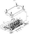
FIG. 6 is a perspective view of a cooling structure for the electronic relay module ofFIG. 4 . -
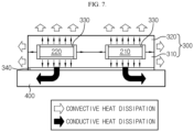
FIG. 7 is a conceptual view of a cooling structure of an electronic relay module according to an embodiment of the present disclosure. - Hereinafter, preferred embodiments of the present disclosure will be described in detail with reference to the accompanying drawings. Prior to the description, it should be understood that the terms used in the specification and the appended claims should not be construed as limited to general and dictionary meanings, but interpreted based on the meanings and concepts corresponding to technical aspects of the present disclosure on the basis of the principle that the inventor is allowed to define terms appropriately for the best explanation. Therefore, the description proposed herein is just a preferable example for the purpose of illustrations only, not intended to limit the scope of the present disclosure, so it should be understood that other equivalents and modifications could be made thereto without departing from the scope of the present disclosure.
- Since embodiments of the present disclosure are provided to more completely explain the present disclosure to those skilled in the art, the shapes and sizes of components in the drawings may be exaggerated, omitted, or schematically illustrated for clearer description. Thus, the size or proportion of each component do not fully reflect an actual size or proportion thereof.
-
FIG. 2 is a perspective view of a battery disconnect unit according to an embodiment of the present disclosure,FIG. 3 is a plan view of the battery disconnect unit ofFIG. 2 from which an top cover has been omitted,FIG. 4 is an exploded perspective view of an electronic relay module according to an embodiment of the present disclosure, andFIG. 5 is a combined perspective view of the electronic relay module ofFIG. 4 . - Referring to these drawings, the battery disconnect unit according to an embodiment of the present disclosure includes a
BDU housing 100, anelectronic relay module 200, aheat dissipation cover 300, acooling plate 400, arefrigerant supply pipe 500, and arefrigerant discharge pipe 600. - The BDU
housing 100 includes alower housing 110 and antop cover 120 provided to be combinable with each other. The BDUhousing 100 may be manufactured by injection molding, for example, a plastic resin. - The
lower housing 110 has a box shape with an open top and is provided so that anelectronic relay module 200, a current sensor, apre-charge resistor 240, a plurality ofbus bars 114, a cable, and the like may be installed therein. For example, as shown in the drawings, the various electrical components may be fixedly mounted on thelower housing 110 by using bolts/nuts or the like. - The
top cover 120 has a shape with an open lower surface, and may be combinably provided over thelower housing 110. - For example, the
lower housing 110 may includesupport rods 111 protruding upward in the form of columns at four corner areas, and thetop cover 120 may include fourmounting portions 121 formed to be flat to face-to-face contact upper end surfaces of thesupport rods 111. Holes are further formed in the four mountingportions 121, and, when hexagonal bolts B are inserted into the holes and fastened to thesupport rods 111, thetop cover 120 may be fixedly coupled to thelower housing 110. - After the
lower housing 110 is coupled with thetop cover 120, theBDU housing 100 may be configured to have a sealed shape, except for an opening for entry of cables or the bus bars 114 for forming a charge/discharge line or connection of connectors on side portions of theBDU housing 100 and a lower side for connecting thecooling plate 400 for cooling theelectronic relay module 200, which will be described later. - By reference, the battery disconnect unit according to the present embodiment is a component of a battery pack and may be installed within a pack case (not shown) that constitutes the battery pack. The battery disconnect unit may include four brackets under lower ends of the four corners of the
lower housing 110, respectively, such that the four brackets may be used when the battery disconnect unit is installed inside the pack case. - The
electronic relay module 200 may be installed to be located on a charge/discharge line of a battery inside theBDU housing 100. The battery refers to secondary battery cells included in the battery pack, the discharge line of the battery refers to a line connecting the battery to a device receiving power from the battery, such as a motor or an inverter of an electric vehicle, and the charge line of the battery refers to a line connecting a charger outside the battery pack to the battery. - The
electronic relay module 200 includes electronic switch devices and selectively blocks the flow of a current in the charge/discharge line of the battery to stably supply power of a high voltage battery to, for example, the motor, or interrupt the supply of the power. - A conventional electro-mechanical relay module includes, for example, a main relay, a pre-charge relay, a pre-charge resistor, and the like. The main relay supplies or blocks power between a high-voltage battery and a motor, and the pre-charge relay and the pre-charge resistor prevents damage to a device due to an initial current. In the
electronic relay module 200 according to the present disclosure, an electronic switch device plays the role of the main relay and the precharge relay of the electro-mechanical relay. - The electronic switch device is a semiconductor switch device for ON or OFF control, and may include one or more metal oxide semiconductor field effect transistors (MOSFETs) or one or more insulated gate bipolar transistors (IGBTs).
- In detail, referring to
FIG. 4 , theelectronic relay module 200 according to the present embodiment includes a firstelectronic relay 210, a secondelectronic relay 220, and agate driver 230. - The first
electronic relay 210 includes a first IGBT circuit unit, afirst device case 211 for protecting the first IGBT circuit unit, and firstterminal portions first device case 211. The secondelectronic relay 220 includes a second IGBT circuit unit configured to have a circuit such that the flow of a current is induced in a reverse direction compared to the first IGBT circuit unit, asecond device case 221 surrounding the second IGBT circuit unit, and secondterminal portions second device case 221. The firstelectronic relay 210 and the secondelectronic relay 220 may be configured to be substantially the same as each other externally. - The first
electronic relay 210 is connected to a positive electrode terminal B(+) of a battery and a positive electrode terminal HV+ of an external device via abus bar 114 to selectively block the flow of a current in a high potential line. The secondelectronic relay 220 is connected to a negative electrode terminal B(-) of the battery and a negative electrode terminal HV- of the external device via anotherbus bar 114 to selectively block the flow of a current in a low potential line. - In the first
electronic relay 210, the firstterminal portion 212 from among the two firstterminal portions bus bar 114, and the firstterminal portion 213 from among the two firstterminal portions other bus bar 114. In the secondelectronic relay 220, the secondterminal portion 223 from among the two secondterminal portions bus bar 114, and the secondterminal portion 222 from among the two secondterminal portions bus bar 114. - The
gate driver 230 is connected to the firstelectronic relay 210 and the secondelectronic relay 220 to control a switching operation of the electronic switch device. - The
gate driver 230 is communicable with a Battery Management System (BMS), and may be configured to turn on or off the electronic switch device according to a signal received from the BMS. - The
gate driver 230 may be connected to the firstelectronic relay 210 and the secondelectronic relay 220 by using metal pins P. - In particular, the
gate driver 230 according to the present embodiment may be implemented as a printed circuit board (PCB), and a plate surface thereof may be arranged perpendicular to the firstelectronic relay 210 or the secondelectronic relay 220. - For example, as shown in
FIG. 4 , thegate driver 230 may be arranged upright on left sides of the firstelectronic relay 210 and the secondelectronic relay 220, and may be integrally formed with the firstelectronic relay 210 and the secondelectronic relay 220 by the metal pins P formed of a rigid material. Thegate driver 230 may be stably vertically arranged on thelower housing 110 by asupport 260 provided such that its one end is bolt-fastened to thelower housing 110 and its other end is bolt-fastened to thegate driver 230. - The
gate driver 230 may include a bus bar passage portion O configured to have a lower end partially recessed. Thebus bar 114 forming a charge/discharge line may pass through the bus bar passage portion O and may be connected to theterminal portion 213 of the firstelectronic relay 210 or theterminal portion 223 of the secondelectronic relay 220 without bypassing thegate driver 230. - According to the above-described structure, the area of the
lower housing 110 may be used more widely. In other words, when thegate driver 230 in the shape of a PCB is arranged perpendicular to a bottom surface of thelower housing 110, a space for mounting other components may be secured, and cable wiring may become easier. For example, as shown inFIG. 3 , because thegate driver 230 is placed upright, it is easy to arrange components, such as thepre-charge resistor 240 and a fuse, adjacent to each other and simply connect them with a cable. - The
heat dissipation cover 300 is a component for cooling and protecting theelectronic relay module 200, and may be formed of a material capable of heat exchange with theelectronic relay module 200 and may be provided to have a structure surrounding the firstelectronic relay 210 and the secondelectronic relay 220. - Referring back to
FIGS. 4 and5 , theheat dissipation cover 300 according to the present embodiment may include alower cover 310 and anupper cover 320 provided to be coupled to each other, and thelower cover 310 and theupper cover 320 may be formed of a material having excellent thermal conductivity, such as aluminum or graphite. - The
lower cover 310 may be provided in a block shape including threefirst protrusions lower cover 310 and two firstaccommodating grooves first protrusion 312 at the center of thelower cover 310. - The
upper cover 320 may be provided in a block shape including threesecond protrusions accommodating grooves first protrusions accommodating grooves lower cover 310 in a vertical direction. - The first
electronic relay 210 and the secondelectronic relay 220 may be seated on the two firstaccommodating grooves lower cover 310. At this time,heat transfer pads 330 may be first placed on respective surfaces of the first accommodating grooves to eliminate heat contact resistance according to a surface roughness difference between thelower cover 310, the firstelectronic relay 210, and the secondelectronic relay 220, thereby increasing heat conductivity. - An upper portion of the first
electronic relay 210 and an upper portion of the secondelectronic relay 220 may be covered with theupper cover 320. At this time, otherheat transfer pads 330 may be arranged on the upper portion of the firstelectronic relay 210 and the upper portion of the secondelectronic relay 220, and upper portions of the otherheat transfer pads 330 may be covered with theupper cover 320. The threefirst protrusions lower cover 310 may be fastened to the threesecond protrusions upper cover 320 by using the bolts B. A plate-shaped washer W may be added between thefirst protrusions second protrusions - According to this structure, the first
electronic relay 210 and the secondelectronic relay 220 may be constrained in spaces formed by the two firstaccommodating grooves accommodating grooves heat dissipation cover 300 has a structure surrounding the firstelectronic relay 210 and the secondelectronic relay 220, when heat is generated in the firstelectronic relay 210 and the secondelectronic relay 220, theheat dissipation cover 300 may quickly absorb the heat. - A heat dissipation structure of the heat dissipation cover will now be described. The
heat dissipation cover 300 according to the present embodiment may be cooled by convective heat dissipation and conductive heat dissipation. In other words, referring toFIGS. 6 and7 , theheat dissipation cover 300 according to the present embodiment may be configured to enable convective heat dissipation through its upper portion and its front, rear, left and right side portions and enable conductive heat dissipation by making thecooling plate 400 contact its lower portion. - To maximize an effect of convective heat dissipation, an upper surface of the
upper cover 320 of theheat dissipation cover 300 may have a structure of a concave-convex pattern 327. In other words, convective heat dissipation is promoted by further increasing a contact area between theupper cover 320 and the atmosphere. - For conductive heat dissipation, the
cooling plate 400 serving as a low temperature body having a lower temperature than theheat dissipation cover 300 is brought into contact with the lower surface of thelower cover 310 of theheat dissipation cover 300. In this case, a thermal interface material (TIM) may be interposed between thelower cover 310 and thecooling plate 400. A material having good thermal conductivity, such as thermal grease, a ceramic-mixed silicone resin, or carbon nanotubes, may be employed as theTIM 340. It may be advantageous for theTIM 340 to have an adhesive pad form rather than a liquid form in adhesively fixing thelower cover 310 to thecooling plate 400. - The
cooling plate 400 may include a flow path formed in a hollow structure through which a refrigerant may flow, and may be provided in the form of a plate-shaped body. Thecooling plate 400 is arranged under theheat dissipation cover 300 to cool theheat dissipation cover 300. - The
refrigerant supply pipe 500 and therefrigerant discharge pipe 600 may be connected to one side or another side of thecooling plate 400, respectively. Therefrigerant supply pipe 500 and therefrigerant discharge pipe 600 may communicate with a refrigerant supply main pipe (not shown) and a refrigerant discharge main pipe (not shown) for cooling the secondary battery cells in a conventional battery pack. - The
refrigerant supply pipe 500 and therefrigerant discharge pipe 600 may communicate with the flow path within thecooling plate 400. The refrigerant may be cooling water, and is introduced into thecooling plate 400 via therefrigerant supply pipe 500 to absorb heat conductively dissipated by theheat dissipation cover 300, and is discharged from thecooling plate 400 through therefrigerant discharge pipe 600. - A flow rate of the refrigerant to be introduced into the
cooling plate 400 via therefrigerant supply pipe 500 may be controlled by the BMS. For example, a temperature sensor capable of measuring the temperature of theelectronic relay module 200 may be included in thelower housing 110, and data measured by the temperature sensor may be transmitted to the BMS. A flow rate of the refrigerant to be supplied to thecooling plate 400 may be differently adjusted by the BMS according to the temperature of theelectronic relay module 200. - According to the present embodiment, the
heat dissipation cover 300 is fixedly arranged on an upper portion of thelower housing 110, and thecooling plate 400 is fixedly arranged on a lower portion of thelower housing 110. A bottom of thelower housing 110 under theheat dissipation cover 300 is open. - In addition, in the battery disconnect unit according to the present embodiment (see
FIGS. 2 and3 ), theheat dissipation cover 300 surrounding the firstelectronic relay 210 and the secondelectronic relay 220 is fixedly arranged on the upper portion of thelower housing 110 by using bolts, and a bracket BK for mounting component parts is disposed on an upper portion of theheat dissipation cover 300. The bracket BK for mounting component parts is used to support thepre-charge resistor 240, and covers the upper surface of theheat dissipation cover 300 but forms a predetermined separation space between the bracket BK and theheat dissipation cover 300, thereby enabling convective heat dissipation of theheat dissipation cover 300. The bottom of thelower housing 110 under theheat dissipation cover 300 may be partially open. Through this open structure, a lower surface of theheat dissipation cover 300 may contact an upper surface of thecooling plate 400. - Such a battery disconnect unit according to the present disclosure has no worries about a contact welding phenomenon and may be made smaller and lighter than conventional battery disconnect units because the battery disconnect unit includes the
electronic relay module 200 using electronic switch devices instead of large-sized electro-mechanical relays. Moreover, the electronic switch devices of theelectronic relay module 200 may be managed to have optimal temperatures, and thus operation reliability and lifespan characteristics of the electronic switch devices may be improved. - A battery pack according to the present disclosure may further include one or more battery modules, various devices (not shown) for controlling charging/discharging of the battery modules, such as a BMS, a current sensor, and a fuse, and a pack case for accommodating them, in addition to the above-described battery disconnect unit.
- Battery packs according to the present disclosure may be applied to vehicles such as electric vehicles or hybrid vehicles. In other words, a vehicle according to the present disclosure may be configured with the above-described battery disconnect unit according to an embodiment of the present disclosure and a battery pack including the above-described battery disconnect unit.
- The present disclosure has been described in detail. However, it should be understood that the detailed description and specific examples, while indicating preferred embodiments of the present disclosure, are given by way of illustration only, since various changes and modifications within the scope of the present disclosure will become apparent to those skilled in the art from this detailed description.
- Meanwhile, although terms indicating directions such as up, down, left, and right are used in the present specification, these terms are only for convenience of description, and it is apparent to those skilled in the art that these terms may vary depending on a position of a target object or a position of an observer.
Claims (12)
- A battery disconnect unit comprising:a BDU housing;an electronic relay module installed on a charge/discharge line of a battery within the BDU housing and comprising electronic switch devices capable of a switching operation of selectively blocking a flow of a current in the charge/discharge line;a heat dissipation cover provided with a structure surrounding at least a portion of the electronic relay module and formed of a material capable of heat exchange with the electronic relay module; anda cooling plate disposed in contact with the heat dissipation cover and provided to allow a refrigerant to flow in the cooling plate.
- The battery disconnect unit of claim 1, wherein the electronic relay module comprises:a first electronic relay installed on a line that connects a positive electrode terminal of the battery to a positive electrode terminal of an external device;a second electronic relay installed on a line that connects a negative electrode terminal of the battery to a negative electrode terminal of the external device; anda gate driver connected to the first electronic relay and the second electronic relay and configured to control a switching operation of the electronic switch device.
- The battery disconnect unit of claim 2, wherein the gate driver is implemented in a form of a printed circuit board, and a plate surface of the gate driver is disposed perpendicular to the first electronic relay or the second electronic relay.
- The battery disconnect unit of claim 2, wherein the heat dissipation cover comprises an upper cover and a lower cover provided to be coupled to each other,the lower cover is provided in a form of a block comprising three first protrusions on both edges and a center region of the lower cover, respectively, and two first accommodating grooves concavely formed on both sides of the first protrusion located on the center region,the upper cover is provided in a form of a block comprising three second protrusions and two second accommodating grooves corresponding to the three first protrusions and the two first accommodating grooves of the lower cover in a vertical direction, andthe first electronic relay and the second electronic relay are respectively constrained in spaces formed by the two first accommodating grooves and the two second accommodating grooves, respectively.
- The battery disconnect unit of claim 4, wherein first heat transfer pads are provided on surfaces of the first accommodating grooves and surfaces of the second accommodating grooves.
- The battery disconnect unit of claim 4, wherein a thermal interface material is provided between a lower surface of the lower cover and the cooling plate.
- The battery disconnect unit of claim 4, wherein the upper cover has an upper surface having a convex-concave pattern structure.
- The battery disconnect unit of claim 1, wherein each of the electronic switch devices is an insulated gate bipolar transistor (IGBT) or a metal oxide semiconductor field effect transistor (MOSFET).
- The battery disconnect unit of claim 1, wherein the BDU housing comprises a lower housing and an top cover provided to be coupled to each other,the heat dissipation cover is fixedly disposed above the lower housing,the cooling plate is fixedly disposed below the lower housing, anda portion of the lower housing below the heat dissipation cover is open so that the heat dissipation cover and the cooling plate contact each other.
- The battery disconnect unit of claim 9, further comprising a refrigerant supply pipe connected to one side of the cooling plate and a refrigerant discharge pipe connected to another side of the cooling plate.
- A battery pack including the battery disconnect unit of any of claims 1 through 10.
- An electric vehicle comprising the battery pack of claim 11.
Applications Claiming Priority (2)
| Application Number | Priority Date | Filing Date | Title |
|---|---|---|---|
| KR1020200136057A KR20220052103A (en) | 2020-10-20 | 2020-10-20 | Battery Disconnect Unit |
| PCT/KR2021/014523 WO2022086101A1 (en) | 2020-10-20 | 2021-10-18 | Battery disconnect unit |
Publications (2)
| Publication Number | Publication Date |
|---|---|
| EP4141904A1 true EP4141904A1 (en) | 2023-03-01 |
| EP4141904A4 EP4141904A4 (en) | 2023-12-13 |
Family
ID=81289924
Family Applications (1)
| Application Number | Title | Priority Date | Filing Date |
|---|---|---|---|
| EP21883170.9A Pending EP4141904A4 (en) | 2020-10-20 | 2021-10-18 | Battery disconnect unit |
Country Status (6)
| Country | Link |
|---|---|
| US (1) | US20230309278A1 (en) |
| EP (1) | EP4141904A4 (en) |
| JP (1) | JP2023524839A (en) |
| KR (1) | KR20220052103A (en) |
| CN (1) | CN115516594A (en) |
| WO (1) | WO2022086101A1 (en) |
Families Citing this family (1)
| Publication number | Priority date | Publication date | Assignee | Title |
|---|---|---|---|---|
| CN117477362B (en) * | 2023-12-26 | 2024-03-15 | 湖南湘电绿能智控有限公司 | High-voltage control cabinet and temperature control system thereof |
Family Cites Families (9)
| Publication number | Priority date | Publication date | Assignee | Title |
|---|---|---|---|---|
| JPH10144836A (en) * | 1996-11-06 | 1998-05-29 | Meidensha Corp | Cooling structure of semiconductor switch |
| KR101185735B1 (en) * | 2010-07-16 | 2012-09-26 | 엘에스산전 주식회사 | Battery disconnect unit for electric vehicle |
| FR3004513B1 (en) | 2013-04-11 | 2015-04-03 | Gaztransp Et Technigaz | METHOD AND SYSTEM FOR PROCESSING AND DELIVERING NATURAL GAS TO ENERGY PRODUCTION EQUIPMENT FOR VESSEL PROPULSION |
| KR101674466B1 (en) * | 2015-05-06 | 2016-11-10 | 주식회사 선우테크 | Water cooling apparatus for IGBT element of electric locomotive |
| CN109075581B (en) * | 2016-05-12 | 2022-10-21 | 罗伯特·博世有限公司 | Battery disconnection circuit and method for controlling battery disconnection circuit |
| KR102080867B1 (en) * | 2016-10-06 | 2020-02-24 | 엘지전자 주식회사 | Heat exchanger for cooling IGBT module |
| KR102606008B1 (en) * | 2019-01-22 | 2023-11-24 | 엘지마그나 이파워트레인 주식회사 | Semiconductor device and cooling apparatus thereof |
| CN210778713U (en) * | 2019-09-05 | 2020-06-16 | 东软睿驰汽车技术(沈阳)有限公司 | Battery pack |
| CN111525211B (en) * | 2020-04-28 | 2022-11-18 | 蜂巢能源科技有限公司 | Control assembly for battery pack, battery pack and vehicle |
-
2020
- 2020-10-20 KR KR1020200136057A patent/KR20220052103A/en unknown
-
2021
- 2021-10-18 US US18/020,131 patent/US20230309278A1/en active Pending
- 2021-10-18 JP JP2022567768A patent/JP2023524839A/en active Pending
- 2021-10-18 WO PCT/KR2021/014523 patent/WO2022086101A1/en unknown
- 2021-10-18 EP EP21883170.9A patent/EP4141904A4/en active Pending
- 2021-10-18 CN CN202180033435.4A patent/CN115516594A/en active Pending
Also Published As
| Publication number | Publication date |
|---|---|
| CN115516594A (en) | 2022-12-23 |
| EP4141904A4 (en) | 2023-12-13 |
| US20230309278A1 (en) | 2023-09-28 |
| KR20220052103A (en) | 2022-04-27 |
| JP2023524839A (en) | 2023-06-13 |
| WO2022086101A1 (en) | 2022-04-28 |
Similar Documents
| Publication | Publication Date | Title |
|---|---|---|
| US11695282B2 (en) | Battery device | |
| JP3637163B2 (en) | Energy storage power supply | |
| ES2641639T3 (en) | Battery disconnection unit structure for electric vehicle | |
| US20220189719A1 (en) | Circuit assembly | |
| US10938006B2 (en) | Connection member, electric component unit, and battery device | |
| KR20190084849A (en) | Switchable battery module | |
| US20220320600A1 (en) | Battery module, and electric vehicle and power storage device comprising battery module | |
| EP4007042B1 (en) | Upper part cooling-type battery pack | |
| EP4141904A1 (en) | Battery disconnect unit | |
| CN113708014A (en) | Battery module with a plurality of battery cells | |
| US20220077549A1 (en) | Battery system with advanced battery disconnecting unit | |
| US20220418085A1 (en) | Circuit structure | |
| EP4095981A1 (en) | Power supply device, and electric vehicle and power storage device equipped with this power supply device | |
| US20230226929A1 (en) | Battery module, power supply device comprising battery module, and electric vehicle and power storage device comprising power supply device | |
| US20140079959A1 (en) | Battery for Motorized Vehicles | |
| JP2012033299A (en) | Power storage device | |
| US20230347746A1 (en) | Power distribution device | |
| JP6144128B2 (en) | Battery for vehicle | |
| WO2018070310A1 (en) | Battery device | |
| CN217468300U (en) | Contactor device, battery pack and power device | |
| JP7486097B2 (en) | Battery Disconnect Unit | |
| US20230335852A1 (en) | Battery pack and vehicle including same | |
| JP7486096B2 (en) | Battery Disconnect Unit | |
| KR20190063065A (en) | Low voltage dc-dc converter with a built-in battery | |
| US11776890B2 (en) | Power semiconductor device |
Legal Events
| Date | Code | Title | Description |
|---|---|---|---|
| STAA | Information on the status of an ep patent application or granted ep patent |
Free format text: STATUS: THE INTERNATIONAL PUBLICATION HAS BEEN MADE |
|
| PUAI | Public reference made under article 153(3) epc to a published international application that has entered the european phase |
Free format text: ORIGINAL CODE: 0009012 |
|
| STAA | Information on the status of an ep patent application or granted ep patent |
Free format text: STATUS: REQUEST FOR EXAMINATION WAS MADE |
|
| 17P | Request for examination filed |
Effective date: 20221122 |
|
| AK | Designated contracting states |
Kind code of ref document: A1 Designated state(s): AL AT BE BG CH CY CZ DE DK EE ES FI FR GB GR HR HU IE IS IT LI LT LU LV MC MK MT NL NO PL PT RO RS SE SI SK SM TR |
|
| A4 | Supplementary search report drawn up and despatched |
Effective date: 20231113 |
|
| RIC1 | Information provided on ipc code assigned before grant |
Ipc: H01M 50/583 20210101ALI20231107BHEP Ipc: H01M 50/287 20210101ALI20231107BHEP Ipc: H01M 50/271 20210101ALI20231107BHEP Ipc: H01M 50/249 20210101ALI20231107BHEP Ipc: H01M 50/204 20210101ALI20231107BHEP Ipc: H05K 7/20 20060101ALI20231107BHEP Ipc: H01M 50/20 20210101ALI20231107BHEP Ipc: H01H 50/12 20060101AFI20231107BHEP |
|
| DAV | Request for validation of the european patent (deleted) | ||
| DAX | Request for extension of the european patent (deleted) |