EP4141438A1 - Humidity sensor and air conditioner - Google Patents
Humidity sensor and air conditioner Download PDFInfo
- Publication number
- EP4141438A1 EP4141438A1 EP20934416.7A EP20934416A EP4141438A1 EP 4141438 A1 EP4141438 A1 EP 4141438A1 EP 20934416 A EP20934416 A EP 20934416A EP 4141438 A1 EP4141438 A1 EP 4141438A1
- Authority
- EP
- European Patent Office
- Prior art keywords
- humidity
- distance
- temperature
- sensor
- humidity sensor
- Prior art date
- Legal status (The legal status is an assumption and is not a legal conclusion. Google has not performed a legal analysis and makes no representation as to the accuracy of the status listed.)
- Granted
Links
Images


Classifications
-
- G—PHYSICS
- G01—MEASURING; TESTING
- G01N—INVESTIGATING OR ANALYSING MATERIALS BY DETERMINING THEIR CHEMICAL OR PHYSICAL PROPERTIES
- G01N29/00—Investigating or analysing materials by the use of ultrasonic, sonic or infrasonic waves; Visualisation of the interior of objects by transmitting ultrasonic or sonic waves through the object
- G01N29/02—Analysing fluids
- G01N29/024—Analysing fluids by measuring propagation velocity or propagation time of acoustic waves
-
- G—PHYSICS
- G01—MEASURING; TESTING
- G01N—INVESTIGATING OR ANALYSING MATERIALS BY DETERMINING THEIR CHEMICAL OR PHYSICAL PROPERTIES
- G01N29/00—Investigating or analysing materials by the use of ultrasonic, sonic or infrasonic waves; Visualisation of the interior of objects by transmitting ultrasonic or sonic waves through the object
- G01N29/22—Details, e.g. general constructional or apparatus details
- G01N29/32—Arrangements for suppressing undesired influences, e.g. temperature or pressure variations, compensating for signal noise
- G01N29/326—Arrangements for suppressing undesired influences, e.g. temperature or pressure variations, compensating for signal noise compensating for temperature variations
-
- F—MECHANICAL ENGINEERING; LIGHTING; HEATING; WEAPONS; BLASTING
- F24—HEATING; RANGES; VENTILATING
- F24F—AIR-CONDITIONING; AIR-HUMIDIFICATION; VENTILATION; USE OF AIR CURRENTS FOR SCREENING
- F24F2110/00—Control inputs relating to air properties
- F24F2110/20—Humidity
-
- G—PHYSICS
- G01—MEASURING; TESTING
- G01N—INVESTIGATING OR ANALYSING MATERIALS BY DETERMINING THEIR CHEMICAL OR PHYSICAL PROPERTIES
- G01N2291/00—Indexing codes associated with group G01N29/00
- G01N2291/02—Indexing codes associated with the analysed material
- G01N2291/028—Material parameters
- G01N2291/02845—Humidity, wetness
Definitions
- the present invention relates to a humidity sensor measuring humidity in a non-contact manner and an air-conditioning apparatus equipped with the humidity sensor.
- a wet-and-dry-bulb psychrometer As devices measuring air humidity, a wet-and-dry-bulb psychrometer, a hair tension hygrometer, a dew-point detecting sensor, a thermistor humidity sensor, a lithium chloride humidity sensor, a ceramic humidity sensor, and polymer film humidity sensor are well known.
- a humidity measurement using change in sound velocity and a scattering phenomenon of ultrasound waves due to air moisture is also known.
- a humidity sensor that measures air humidity based on an attenuation ratio of ultrasound waves and temperature has been proposed in Patent Literature 1.
- Patent Literature 1 Japanese Unexamined Utility Model Registration Application Publication No. 7-26759
- the humidity sensor described in Patent Literature 1 has a configuration in which a transmitter transmitting ultrasound waves and a receiver receiving the ultrasound waves transmitted from the transmitter are arranged to face each other with a certain distance therebetween.
- the transmitter and the receiver need to be arranged separately from each other. This leads to not only a reduction in the usability but also enlargement of the humidity sensor.
- the present invention has been made to overcome the above-mentioned problems, and has an object to provide a humidity sensor and an air-conditioning apparatus with a reduced size capable of measuring humidity in a non-contact manner.
- a humidity sensor includes a sound wave element configured to transmit a sound wave and receive the sound wave reflected by a reflector, a reception circuit configured to obtain an arrival time of the reflected wave received by the sound wave element, and a humidity analysis circuit configured to calculate humidity by using the arrival time, a distance from the sound wave element to the reflector, and a temperature of a space from the sound wave element to the reflector.
- An air-conditioning apparatus includes the abovementioned humidity sensor, a heat exchanger, and a fan.
- the size of the non-contact humidity sensor can be reduced.
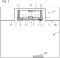
- FIG. 1 is a schematic diagram of an air-conditioning apparatus 100 equipped with a humidity sensor 7 according to Embodiment 1.
- the air-conditioning apparatus 100 is a ceiling embedded type indoor unit that is installed on a ceiling 300 of a room 200, which is an air-conditioned space.
- the room 200 is an office space for business use or an indoor space of a general house.
- the ceiling 300 is installed at a height of two meters or more in the room 200.
- the air-conditioning apparatus 100 is installed at an installation opening, which is formed by removing a part of the ceiling 300.
- the room 200 is provided with a reflector 400.
- the reflector 400 is a metallic plate, a resin plate or a wood plate, and is installed on a floor surface or a wall surface of the room 200.
- a face of the reflector 400 facing the inside of the room 200 has a smooth surface. Note that, instead of installing the reflector 400 individually, a part of the floor surface or a part of the wall surface of the room 200 can be used as the reflector 400.
- the air-conditioning apparatus 100 is a package type air-conditioning apparatus having a cooling function, a heating function, and a humidification function. Note that, the air-conditioning apparatus 100 may be a cassette type air conditioner, a room air conditioner, an outdoor air treating unit, or a similar device. As shown in FIG. 1 , the air-conditioning apparatus 100 includes a casing 1, a filter 2, a fan 3, a heat exchanger 4, a humidification element 5, a controller 6, and a humidity sensor 7.
- the casing 1 is formed in a box shape and has a bottom 10 exposed on the ceiling 300.
- An air inlet 11 is provided at the center of a bottom 10, and an air outlet 12 is provided along the four sides of the bottom 10.
- the filter 2 is installed on the downstream of the air inlet 11 to collect dust in the air sucked from the air inlet 11.
- the fan 3 is arranged between the filter 2 and the heat exchanger 4 in the casing 1.
- the fan 3 is, for example, an axial fan, and is driven by a motor 30.
- the motor 30 is controlled by the controller 6.
- the heat exchanger 4 is installed on the downstream of the fan 3.
- the heat exchanger 4 exchanges heat between refrigerant flowing therein and air taken into the casing 1 from the air inlet 11.
- the heat exchanger 4 is connected, by a refrigerant pipe, to an outdoor unit (not shown) having a compressor and a heat exchanger, thereby forming a part of a refrigerant circuit.
- the heat exchanger 4 has, for example, a fin-and-tube structure made of aluminum.
- the heat exchanger 4 functions as a condenser in a heating operation to heat the air and functions as an evaporator in a cooling operation to cool the air.
- the heat exchanger 4 may be obliquely arranged in such a manner that a lower end portion is placed on the upstream side and an upper end portion is placed on the downstream side.
- the humidification element 5 is formed by, for example, stacking a plurality of paper or resin sheets having a porous or fibrous property.
- the humidification element 5 is arranged on the downstream of the heat exchanger 4 along the heat exchanger 4.
- the length of a long side of the humidification element 5 is substantially the same as the length of a long side of the heat exchanger 4.
- the humidification element 5 absorbs water supplied from a water supply tank, which is not shown, installed above.
- water evaporates from the humidification element 5, thereby humidifying the air.
- tap water or industrial water can be used as the water, it is preferable that water containing fewer scale components, such as potassium, magnesium, and silica, which cause deposition, be used.
- the humidification element 5 may be omitted and the air-conditioning apparatus 100 may be configured to have no humidification function.
- the controller 6 is formed by using dedicated hardware, such as an application-specific integrated circuit (ASIC) or a field-programmable gate array (FPGA), a processing device, such as a microcomputer executing a program stored in a memory, or both of them.
- the controller 6 is configured to control a rotation speed of the motor 30 based on the temperature or the humidity of the room 200. As shown by broken arrows in FIG. 1 , by rotating the fan 3 by the motor 30, air is sucked from the air inlet 11.
- the air passes through the filter 2 and dust is thereby removed from the air, the air passes through the heat exchanger 4. After the air is cooled or heated by the heat exchanger 4, the air is then humidified when passing through the humidification element 5. The air is thus conditioned and discharged from the air outlet 12.
- the humidity sensor 7 is a device that measures the humidity in the room 200 in a non-contact manner.
- the humidity sensor 7 includes an ultrasound element 71 that transmits and receives ultrasound waves.
- the ultrasound element 71 is arranged on the bottom 10 of the casing 1 at a position between the air inlet 11 and the air outlet 12.
- one ultrasound element 71 is arranged on the left side or right side of the air inlet 11 in such a manner as to face the reflector 400.
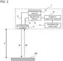
- FIG. 2 is a diagram illustrating the configuration of the humidity sensor 7 according to Embodiment 1.
- the humidity sensor 7 includes the ultrasound element 71, a transmission circuit 73, a reception circuit 75, a humidity analysis circuit 76, and an information input unit 77.
- the ultrasound element 71 includes a piezoelectric ceramic and electrodes, and is configured to transmit and receive ultrasound waves. When a high frequency voltage is applied to the piezoelectric ceramic from one electrode, the piezoelectric ceramic contracts and expands repeatedly, and this vibration generates ultrasound waves.
- the ultrasound element 71 can transmit sound waves having a frequency of 20 kHz or higher, that is ultrasound waves, and can receive and convert ultrasound waves in air into voltage.
- the ultrasound element 71 of the present embodiment is a single element that can transmit ultrasound waves from the ceiling 300 of the room 200 to the reflector 400, and can receive reflected ultrasound waves returning from the reflector 400.
- the ultrasound element 71 is connected to the transmission circuit 73 via an electric wire 72.
- the transmission circuit 73 is configured to supply a pulse wave to the ultrasound element 71.
- the ultrasound element 71 is also connected to the reception circuit 75 via an electric wire 74.
- the reception circuit 75 is configured to amplify an output from the ultrasound element 71 and perform an analog-to-digital (A/D) conversion of the output. Because the output from the ultrasound element 71 is an analog signal, the reception circuit 75 is provided with an A/D converter converting an analog signal into a digital signal.
- the sampling frequency of the A/D conversion in the reception circuit 75 is 2.4 MHz, and the resolution is 12 bits. It is preferable that the sampling frequency be twice or more times the frequency of the pulse wave applied to the ultrasound element 71. The sampling frequency is, for example, eight times the applied voltage.
- the reception circuit 75 is configured to analyze a converted digital signal to obtain a reflected wave arrival time t (ms). The reception circuit 75 is configured to input the obtained reflected wave arrival time t to the humidity analysis circuit 76.
- the humidity analysis circuit 76 is configured to obtain a relative humidity U (% RH) of the room 200 by using the reflected wave arrival time t input from the reception circuit 75, and a temperature T (°C) and a distance D (m) input from the information input unit 77.
- the temperature T is the temperature of a space between the ultrasound element 71 and the reflector 400, and is the temperature of the room 200, for example.
- the distance D is the distance between the ultrasound element 71 and the reflector 400.
- the information input unit 77 is configured to input the temperature T of the room 200 and the distance D from the ultrasound element 71 to the reflector 400 to the humidity analysis circuit 76.
- the temperature T and the distance D are input via an input interface, such as a remote controller of the air-conditioning apparatus 100, for example, and are stored in a memory, which is not shown.
- the information input unit 77 is configured to read out the temperature T and the distance D from the memory and input the temperature T and the distance D to the humidity analysis circuit 76.
- the information input unit 77 may be an input interface. Information being input via the information input unit 77 itself may be input to the humidity analysis circuit 76.
- the distance D from the ultrasound element 71 to the reflector 400 may be any distance; however, if the distance D is too long, ultrasound waves are attenuated and cannot reach the reflector 400. An ultrasound wave having a smaller frequency reaches farther but the directivity is increased. When the directivity is increased, irregular reflection of ultrasound waves easily occurs in the room 200. This irregular reflection is unfavorable because waveforms to be detected by the ultrasound element 71 become complicated. Because one side of the room 200 as a living space is about 10 meters in the maximum length, the distance D is 10 meters at maximum. To make an ultrasound wave travel the maximum distance, which is 10 meters, the frequency of a pulse wave supplied to the ultrasound element 71 is set to 40 kHz, for example.
- the transmission circuit 73 applies a pulse wave having a frequency of 40 kHz, for example, to the ultrasound element 71 to cause the ultrasound element 71 to generate an ultrasound wave.
- the output of the transmission circuit 73 is not limited to the pulse wave, and may be a continuous wave, such as a sine wave alternating current.
- the ultrasound wave generated by the ultrasound element 71 reaches the reflector 400 as a transmission wave W1 shown by an arrow in FIG. 2 , and then is reflected by the reflector 400.
- the reflected wave, as a reflected wave W2 is received by the ultrasound element 71.
- the received reflected wave W2 is converted into voltage and is then transmitted to the reception circuit 75 via the electric wire 74.
- the reception circuit 75 converts the reflected wave W2 into a digital signal, and obtains the reflected wave arrival time t from the digital signal.
- the humidity analysis circuit 76 obtains the humidity of the room 200 by using the reflected wave arrival time t obtained by the reception circuit 75, and the temperature T of the room 200 and the distance D from the ultrasound element 71 to the reflector 400 input from the information input unit 77.
- the humidity analysis circuit 76 may be communicably connected to the controller 6 of the air-conditioning apparatus 100 to transmit the obtained humidity to the controller 6.
- the controller 6 of the air-conditioning apparatus 100 may perform air-conditioning control based on the received humidity or may display the received humidity on a display unit (not shown) of the remote controller.
- the humidity analysis circuit 76 may be communicably connected to an external device other than the air-conditioning apparatus 100. The obtained humidity may be transmitted to the external device and displayed on a display unit of the external device.
- the relative humidity U can be derived by a known method by using a state equation and the Tetens' empirical formula.
- the following Formula (1) is derived where U is the relative humidity (% RH), Pd is the pressure of dry air (hPa), T is the temperature (degrees C), c is the speed of sound (m/s), Md is the average molecular weight of dry air, ⁇ is the constant pressure specific heat ratio of air, and R is the universal gas constant (J/K ⁇ mol).
- Formula 1 U P d 6.11 ⁇ 10 exp 7.5 T 237.3 + T ⁇ c 2 M d ⁇ R 273.15 + T ⁇ 1
- the pressure of dry air Pd the average molecular weight of dry air Md
- the constant pressure specific heat ratio ⁇ the universal gas constant R are constants.
- the speed of sound c (m/s) in the Formula (1) is represented by the following Formula (2), where D is the distance to the reflector 400 and t is the reflected wave arrival time.
- Formula 2 c 2 D t
- the relative humidity U can be obtained by using the Formula (1) and the Formula (2).
- the distance D from the ultrasound element 71 to the aluminum wall was 0.525 meters.
- the temperature T in the test tank was kept at 40 °C, and the relative humidity U was changed to 30 %, 40 %, 50 %, 60 %, 70 %, 80 %, and 90 % RH. While ten pulses were applied to the ultrasound element 71, and change in the reflected waves W2 received by the ultrasound element 71 was examined.
- the reception circuit 75 converts each of the reflected wave W2 into a digital signal and then analyzes the digital signal as discrete data.
- FIG. 3 is a graph showing change with time in a reflected wave received by the ultrasound element 71 in a case where the temperature T is 40 °C and the relative humidity U is 30 % RH in the test tank.
- the reflected wave is represented as an output voltage (mV) of the ultrasound element 71.
- An elapsed time of 0 ms indicates a time at which an ultrasound wave is transmitted from the ultrasound element 71.
- the reflected wave of the elapsed time from 0 to 1.5 ms results from a transmission sound of the ultrasound element 71.
- the reception circuit 75 obtains the arrival time t of the reflected wave by squaring and integrating the output voltage shown in FIG. 3 .
- the reflected wave arrival time t was 2.956 ms.
- the reflected wave arrival time t may be obtained based on the waveform of the reflected wave W2. In this case, the time at which the output voltage reaches a certain voltage may be used as the reflected wave arrival time t.
- FIG. 4 is a graph showing change with time in a reflected wave received by the ultrasound element 71 in a case where the temperature T is 40 °C and the relative humidity U is 90 % RH in the test tank.
- the reflected wave arrival time t is obtained by squaring and integrating the output voltage shown in FIG. 4 .
- the reflected wave arrival time t was 2.952 ms.
- FIG. 6 is a graph on which relative humidity values U and reflected wave arrival times t obtained by experiments are plotted. Because data on transmission start time and arrival time of ultrasound waves is analyzed by using a method that the experimenter decides, generally there is a difference in time between the experimental values and the values obtained by calculation using the Formula (1). FIG. 6 indicates that even in the experimental values, the relative humidity U and the reflected wave arrival time t are approximately proportional to each other. From this experiment result, it can be confirmed that humidity can be calculated based on the distance D, the temperature T, and the reflected wave arrival time t.
- the relative humidity U cannot be obtained by using the output voltage itself.
- a relation between the reflected wave arrival time t of the ultrasound element 71 and the relative humidity U which changes according to indoor conditions, that is the distance D and the temperature T, of the room 200 to be measured, is obtained and stored in a storage area of the humidity analysis circuit 76 in advance. Then, by performing calculation using the relation shown in FIG. 6 , the relative humidity U can be obtained for an actual reflected wave arrival time t.
- the relative humidity U 43 %RH can be obtained for a reflected wave arrival time t of 2.951 ms from the relation shown in FIG. 6 .
- FIG. 7 is a graph showing a relation between the distance D from the ultrasound element 71 to the reflector 400 and the reflected wave arrival time t in a case where the temperature T is 40 °C and the relative humidity U is 50 % RH.
- the relation shown in FIG. 7 can be obtained by substituting the parameters into the Formula (1). From FIG. 7 , it can be confirmed that the distance D from the ultrasound element 71 to the reflector 400 and the reflected wave arrival time t are proportional to each other. Therefore, it is clear that, by using experimental data in which the reflected wave arrival times t are obtained by changing the temperature T, the relative humidity U, and the distance D, the relative humidity U can be calculated based on the reflected wave arrival time t.
- the humidity analysis circuit 76 can obtain the relative humidity U by directly substituting the distance D, the temperature T, and the reflected wave arrival time t into the Formula (1).
- the humidity analysis circuit 76 may store, in a storage area, database including a relation between the temperature T, the relative humidity U, the distance D, and the reflected wave arrival time t obtained from experiments and may obtain the relative humidity U based the database and input values of the distance D, the temperature T, and the reflected wave arrival time t.
- the humidity sensor 7 of the present embodiment because transmission and reception of ultrasound waves can be performed by a single ultrasound element 71, the size of the non-contact humidity sensor 7 can be reduced.
- the humidity sensor 7 can obtain the relative humidity U of the room 200 in a non-contact manner based on the three parameters, which are the arrival time t of a reflected wave received by the ultrasound element 71, the temperature T of the room 200, and the distance D to the reflector 400 input from the information input unit 77. Therefore, the degree of freedom in arrangement of the humidity sensor 7 is increased and thus the usability is improved.
- FIG. 8 is a schematic diagram of an air-conditioning apparatus 100A equipped with the humidity sensor 7A according to Embodiment 2.
- the features other than the humidity sensor 7A of the air-conditioning apparatus 100A are the same as those of Embodiment 1.
- the humidity sensor 7A includes the distance sensor 8 measuring the distance to the reflector 400 and the temperature sensor 9 measuring the temperature in the room 200, in addition to the ultrasound element 71.
- the ultrasound element 71, the distance sensor 8, and the temperature sensor 9 are integrally embedded in the humidity sensor 7A.
- the distance sensor 8 and the temperature sensor 9 are arranged on the bottom 10 of the casing 1 at a position between the air inlet 11 and the air outlet 12. In the present embodiment, the distance sensor 8 and the temperature sensor 9 are arranged alongside the ultrasound element 71 on the left side or right side of the air inlet 11 in such a manner as to face the reflector 400.
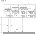
- FIG. 9 is a diagram illustrating the configuration of the humidity sensor 7A according to Embodiment 2.
- the humidity sensor 7A includes the ultrasound element 71, the transmission circuit 73, the reception circuit 75, the humidity analysis circuit 76, the information input unit 77, the distance sensor 8, a distance analysis circuit 81, the temperature sensor 9, and a temperature analysis circuit 91.
- the distance sensor 8 is an optical sensor or a camera.
- the distance sensor 8 is an optical sensor
- light irradiated from a light source in the distance sensor 8 is reflected by the reflector 400 and is received by a light receiving element of the distance sensor 8.
- the reflected light is evaluated or calculated by the distance analysis circuit 81 and converted into distance.
- the distance analysis circuit 81 is configured to measure a time period from irradiation of light to reception of the light, and obtain the distance by converting the time difference into distance.
- the distance analysis circuit 81 is configured to obtain the distance by using a triangulation distance measuring method in which an image formation position of a light receiving element, which varies depending on the distance, is converted into distance.
- the distance sensor 8 is arranged on the same plane as the ultrasound element 71.
- the distance from the distance sensor 8 to the reflector 400 is the same as the distance D from the ultrasound element 71 to the reflector 400.
- the distance analysis circuit 81 is connected to the information input unit 77. The distance calculated by the distance analysis circuit 81 is output to the information input unit 77 in real time.
- the temperature sensor 9 is a contact type sensor, such as a thermocouple or a thermistor, or a non-contact type sensor, such as an infrared sensor.
- the temperature sensor 9 detects infrared radiation energy radiated from the room 200, and the temperature analysis circuit 91 calculates the temperature in a space of the room 200 based on the amount of the detected infrared energy.
- the temperature analysis circuit 91 is connected to the information input unit 77.
- the temperature calculated by the temperature analysis circuit 91 is output to the information input unit 77 in real time.
- the humidity analysis circuit 76 obtains the relative humidity U of the room 200 in the same manner as Embodiment 1 by using the reflected wave arrival time t, the temperature T of the room 200, and the distance D from the ultrasound element 71 to the reflector 400 input from the information input unit 77.
- the distance D from the ultrasound element 71 to the reflector 400 and the temperature T of the room 200 which are required values for obtaining the relative humidity U of the room 200, can be measured by the distance sensor 8 and the temperature sensor 9, and can be input to the humidity analysis circuit 76. Therefore, the calculation of the relative humidity U by the humidity sensor 7A is automated. As a result, there is no need for a user to input the distance D and the temperature T in advance, and thus the usability is further improved. Furthermore, because the actual distance D and the actual temperature T of the room 200 are measured, the accuracy of measurement for the relative humidity U is improved.
- both of the distance sensor 8 and the temperature sensor 9 are installed; however, only either one of them may be installed.
- the distance sensor 8 and the temperature sensor 9 may be installed in an external device other than the humidity sensor 7A.
- the temperature sensor 9 may be an indoor temperature sensor provided in the air-conditioning apparatus 100A.
- the information input unit 77 has a wireless communication function to communicate with the external device. The information input unit 77 receives the temperature T and the distance D from the external device and inputs the temperature T and the distance D to the humidity analysis circuit 76.
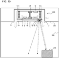
- FIG. 10 is a schematic diagram of an air-conditioning apparatus 100B equipped with the humidity sensor 7B according to Embodiment 3.
- the features of the humidity sensor 7B other than the movable mechanism 78 are the same as those of the humidity sensor 7 of Embodiment 1, and the features other than the humidity sensor 7B of the air-conditioning apparatus 100B are the same as those of Embodiment 1.
- the ultrasound element 71 of the humidity sensor 7B of the present embodiment is held by the movable mechanism 78.
- the movable mechanism 78 includes a motor, a controller configured to control the motor, and a shaft extending parallel to the floor surface of the room 200, which are not shown.
- the ultrasound element 71 is held by the movable mechanism 78, and is moved to scan the floor surface of the room 200.
- the ultrasound element 71 when the ultrasound element 71 transmits an ultrasound wave but does not receive a reflected wave, the ultrasound element 71 keeps moving while transmitting ultrasound waves. Then, a reflected wave is received from any reflector 500, the controller stops the movement of the ultrasound element 71, and the reception circuit 75 performs analysis of the reflected wave arrival time t based on the received reflected wave.
- the humidity analysis circuit 76 obtains the relative humidity U based on the reflected wave arrival time t, the distance D from the ultrasound element 71 to the reflector 500, and the temperature T of the room 200.
- the distance D in this case is obtained from the reflected wave arrival time analyzed by the reception circuit 75 and a relation between distance and reflected wave arrival time stored in advance as a reference.
- the humidity sensor 7B may include the distance sensor 8 of Embodiment 2 to measure the distance to the reflector 500.
- the humidity of the room 200 can be obtained without installing the reflector 400 at a specific position. Therefore, the humidity can be measured in a wide range of the room 200, and thus the usability is further improved.
- the humidity sensor 7 includes the ultrasound element 71 configured to transmit and receive ultrasound waves but the configuration is not limited thereto.
- the humidity sensor 7 may include a sound wave element configured to transmit and receive sound waves.
- the humidity sensor 7 may include a sound wave element that emits an audible sound having a frequency of 20 kHz or below. Even in this case, because the ultrasound wave and the sound wave are different only in the frequency and the wavelength, the sound wave transmitted from the sound wave element is reflected by the reflector 400 and returned to the sound wave element. Therefore, as with the abovementioned embodiments, the humidity of the room 200 can be obtained based on the arrival time of the reflected wave.
- reception circuit 75 and the humidity analysis circuit 76 are provided separately, the function of the reception circuit 75 and the function of the humidity analysis circuit 76 may be incorporated into a single circuit, or may be executed by a microcomputer.
- the function of the distance analysis circuit 81 and the function of the temperature analysis circuit 91 may be incorporated into the same single circuit as the reception circuit 75 and the humidity analysis circuit 76, or may be executed by a microcomputer.
- the transmission circuit 73 and the reception circuit 75 may be integrated into a pulser-receiver.
Landscapes
- Physics & Mathematics (AREA)
- Biochemistry (AREA)
- Health & Medical Sciences (AREA)
- Life Sciences & Earth Sciences (AREA)
- Chemical & Material Sciences (AREA)
- Analytical Chemistry (AREA)
- General Health & Medical Sciences (AREA)
- General Physics & Mathematics (AREA)
- Immunology (AREA)
- Pathology (AREA)
- Acoustics & Sound (AREA)
- Air Conditioning Control Device (AREA)
- Investigating Or Analyzing Materials By The Use Of Ultrasonic Waves (AREA)
Abstract
Description
- The present invention relates to a humidity sensor measuring humidity in a non-contact manner and an air-conditioning apparatus equipped with the humidity sensor.
- Conventionally, as devices measuring air humidity, a wet-and-dry-bulb psychrometer, a hair tension hygrometer, a dew-point detecting sensor, a thermistor humidity sensor, a lithium chloride humidity sensor, a ceramic humidity sensor, and polymer film humidity sensor are well known. In addition, as a technique for measuring humidity in a non-contact manner, a humidity measurement using change in sound velocity and a scattering phenomenon of ultrasound waves due to air moisture is also known. For example, a humidity sensor that measures air humidity based on an attenuation ratio of ultrasound waves and temperature has been proposed in
Patent Literature 1. - Patent Literature 1:
Japanese Unexamined Utility Model Registration Application Publication No. 7-26759 - The humidity sensor described in
Patent Literature 1 has a configuration in which a transmitter transmitting ultrasound waves and a receiver receiving the ultrasound waves transmitted from the transmitter are arranged to face each other with a certain distance therebetween. However, in this configuration, the transmitter and the receiver need to be arranged separately from each other. This leads to not only a reduction in the usability but also enlargement of the humidity sensor. - The present invention has been made to overcome the above-mentioned problems, and has an object to provide a humidity sensor and an air-conditioning apparatus with a reduced size capable of measuring humidity in a non-contact manner.
- A humidity sensor according to an embodiment of the present invention includes a sound wave element configured to transmit a sound wave and receive the sound wave reflected by a reflector, a reception circuit configured to obtain an arrival time of the reflected wave received by the sound wave element, and a humidity analysis circuit configured to calculate humidity by using the arrival time, a distance from the sound wave element to the reflector, and a temperature of a space from the sound wave element to the reflector. An air-conditioning apparatus according to another embodiment of the present invention includes the abovementioned humidity sensor, a heat exchanger, and a fan.
- According to an embodiment of the present invention, because transmission and reception of sound waves can be performed by a single sound wave element, the size of the non-contact humidity sensor can be reduced.
-
- FIG. 1
- is a schematic diagram of an air-conditioning apparatus equipped with a humidity sensor according to
Embodiment 1. - FIG. 2
- is a diagram illustrating the configuration of the humidity sensor according to
Embodiment 1. - FIG. 3
- is a graph showing change with time in a reflected wave received by an ultrasound element in a case where a temperature T is 40 °C and a relative humidity U is 30 % relative humidity (RH) in a test tank.
- FIG. 4
- is a graph showing change with time in a reflected wave received by the ultrasound element in a case where the temperature T is 40 °C and the relative humidity U is 90 % RH in the test tank.
- FIG. 5
- is a graph showing a relation between the relative humidity U obtained by Formula (1) and a reflected wave arrival time t.
- FIG. 6
- is a graph on which the relative humidity values U and the reflected wave arrival times t obtained by experiments are plotted.
- FIG. 7
- is a graph showing a relation between a distance D from the ultrasound element to a reflector and the reflected wave arrival time t in a case where the temperature T is 40 °C and the relative humidity U is 50 % RH.
- FIG. 8
- is a schematic diagram of an air-conditioning apparatus equipped with a humidity sensor according to
Embodiment 2. - FIG. 9
- is a diagram illustrating the configuration of the humidity sensor according to
Embodiment 2. - FIG. 10
- is a schematic diagram of an air-conditioning apparatus equipped with a humidity sensor according to
Embodiment 3. -
FIG. 1 is a schematic diagram of an air-conditioning apparatus 100 equipped with ahumidity sensor 7 according toEmbodiment 1. As shown inFIG. 1 , the air-conditioning apparatus 100 is a ceiling embedded type indoor unit that is installed on aceiling 300 of aroom 200, which is an air-conditioned space. Theroom 200 is an office space for business use or an indoor space of a general house. Theceiling 300 is installed at a height of two meters or more in theroom 200. The air-conditioning apparatus 100 is installed at an installation opening, which is formed by removing a part of theceiling 300. - The
room 200 is provided with areflector 400. Thereflector 400 is a metallic plate, a resin plate or a wood plate, and is installed on a floor surface or a wall surface of theroom 200. A face of thereflector 400 facing the inside of theroom 200 has a smooth surface. Note that, instead of installing thereflector 400 individually, a part of the floor surface or a part of the wall surface of theroom 200 can be used as thereflector 400. - The air-
conditioning apparatus 100 is a package type air-conditioning apparatus having a cooling function, a heating function, and a humidification function. Note that, the air-conditioning apparatus 100 may be a cassette type air conditioner, a room air conditioner, an outdoor air treating unit, or a similar device. As shown inFIG. 1 , the air-conditioning apparatus 100 includes acasing 1, afilter 2, afan 3, aheat exchanger 4, ahumidification element 5, acontroller 6, and ahumidity sensor 7. - The
casing 1 is formed in a box shape and has abottom 10 exposed on theceiling 300. Anair inlet 11 is provided at the center of abottom 10, and anair outlet 12 is provided along the four sides of thebottom 10. Note that, the terms "upstream" and "downstream" in the following description respectively indicate the upstream and the downstream in a flow direction of air from theair inlet 11 to theair outlet 12. Thefilter 2 is installed on the downstream of theair inlet 11 to collect dust in the air sucked from theair inlet 11. Thefan 3 is arranged between thefilter 2 and theheat exchanger 4 in thecasing 1. Thefan 3 is, for example, an axial fan, and is driven by amotor 30. Themotor 30 is controlled by thecontroller 6. - The
heat exchanger 4 is installed on the downstream of thefan 3. Theheat exchanger 4 exchanges heat between refrigerant flowing therein and air taken into thecasing 1 from theair inlet 11. Theheat exchanger 4 is connected, by a refrigerant pipe, to an outdoor unit (not shown) having a compressor and a heat exchanger, thereby forming a part of a refrigerant circuit. Theheat exchanger 4 has, for example, a fin-and-tube structure made of aluminum. - The heat exchanger 4 functions as a condenser in a heating operation to heat the air and functions as an evaporator in a cooling operation to cool the air. The
heat exchanger 4 may be obliquely arranged in such a manner that a lower end portion is placed on the upstream side and an upper end portion is placed on the downstream side. - The
humidification element 5 is formed by, for example, stacking a plurality of paper or resin sheets having a porous or fibrous property. Thehumidification element 5 is arranged on the downstream of theheat exchanger 4 along theheat exchanger 4. The length of a long side of thehumidification element 5 is substantially the same as the length of a long side of theheat exchanger 4. Thehumidification element 5 absorbs water supplied from a water supply tank, which is not shown, installed above. - When air passes through the water-absorbed
humidification element 5, water evaporates from thehumidification element 5, thereby humidifying the air. Although tap water or industrial water can be used as the water, it is preferable that water containing fewer scale components, such as potassium, magnesium, and silica, which cause deposition, be used. Note that, in another embodiment, thehumidification element 5 may be omitted and the air-conditioning apparatus 100 may be configured to have no humidification function. - The
controller 6 is formed by using dedicated hardware, such as an application-specific integrated circuit (ASIC) or a field-programmable gate array (FPGA), a processing device, such as a microcomputer executing a program stored in a memory, or both of them. Thecontroller 6 is configured to control a rotation speed of themotor 30 based on the temperature or the humidity of theroom 200. As shown by broken arrows inFIG. 1 , by rotating thefan 3 by themotor 30, air is sucked from theair inlet 11. - After the air passes through the
filter 2 and dust is thereby removed from the air, the air passes through theheat exchanger 4. After the air is cooled or heated by theheat exchanger 4, the air is then humidified when passing through thehumidification element 5. The air is thus conditioned and discharged from theair outlet 12. - The
humidity sensor 7 is a device that measures the humidity in theroom 200 in a non-contact manner. Thehumidity sensor 7 includes anultrasound element 71 that transmits and receives ultrasound waves. Theultrasound element 71 is arranged on the bottom 10 of thecasing 1 at a position between theair inlet 11 and theair outlet 12. In the present embodiment, oneultrasound element 71 is arranged on the left side or right side of theair inlet 11 in such a manner as to face thereflector 400. -
FIG. 2 is a diagram illustrating the configuration of thehumidity sensor 7 according toEmbodiment 1. As shown inFIG. 2 , thehumidity sensor 7 includes theultrasound element 71, atransmission circuit 73, areception circuit 75, ahumidity analysis circuit 76, and aninformation input unit 77. Theultrasound element 71 includes a piezoelectric ceramic and electrodes, and is configured to transmit and receive ultrasound waves. When a high frequency voltage is applied to the piezoelectric ceramic from one electrode, the piezoelectric ceramic contracts and expands repeatedly, and this vibration generates ultrasound waves. - When the piezoelectric ceramic is vibrated by received ultrasound waves, voltage is generated at both ends of the piezoelectric ceramic in response to this vibration. By using this principle, the
ultrasound element 71 can transmit sound waves having a frequency of 20 kHz or higher, that is ultrasound waves, and can receive and convert ultrasound waves in air into voltage. Theultrasound element 71 of the present embodiment is a single element that can transmit ultrasound waves from theceiling 300 of theroom 200 to thereflector 400, and can receive reflected ultrasound waves returning from thereflector 400. - The
ultrasound element 71 is connected to thetransmission circuit 73 via anelectric wire 72. Thetransmission circuit 73 is configured to supply a pulse wave to theultrasound element 71. Theultrasound element 71 is also connected to thereception circuit 75 via anelectric wire 74. Thereception circuit 75 is configured to amplify an output from theultrasound element 71 and perform an analog-to-digital (A/D) conversion of the output. Because the output from theultrasound element 71 is an analog signal, thereception circuit 75 is provided with an A/D converter converting an analog signal into a digital signal. - The sampling frequency of the A/D conversion in the
reception circuit 75 is 2.4 MHz, and the resolution is 12 bits. It is preferable that the sampling frequency be twice or more times the frequency of the pulse wave applied to theultrasound element 71. The sampling frequency is, for example, eight times the applied voltage. In addition, thereception circuit 75 is configured to analyze a converted digital signal to obtain a reflected wave arrival time t (ms). Thereception circuit 75 is configured to input the obtained reflected wave arrival time t to thehumidity analysis circuit 76. - The
humidity analysis circuit 76 is configured to obtain a relative humidity U (% RH) of theroom 200 by using the reflected wave arrival time t input from thereception circuit 75, and a temperature T (°C) and a distance D (m) input from theinformation input unit 77. The temperature T is the temperature of a space between theultrasound element 71 and thereflector 400, and is the temperature of theroom 200, for example. The distance D is the distance between theultrasound element 71 and thereflector 400. - The
information input unit 77 is configured to input the temperature T of theroom 200 and the distance D from theultrasound element 71 to thereflector 400 to thehumidity analysis circuit 76. The temperature T and the distance D are input via an input interface, such as a remote controller of the air-conditioning apparatus 100, for example, and are stored in a memory, which is not shown. Theinformation input unit 77 is configured to read out the temperature T and the distance D from the memory and input the temperature T and the distance D to thehumidity analysis circuit 76. Alternatively, theinformation input unit 77 may be an input interface. Information being input via theinformation input unit 77 itself may be input to thehumidity analysis circuit 76. - The distance D from the
ultrasound element 71 to thereflector 400 may be any distance; however, if the distance D is too long, ultrasound waves are attenuated and cannot reach thereflector 400. An ultrasound wave having a smaller frequency reaches farther but the directivity is increased. When the directivity is increased, irregular reflection of ultrasound waves easily occurs in theroom 200.
This irregular reflection is unfavorable because waveforms to be detected by theultrasound element 71 become complicated. Because one side of theroom 200 as a living space is about 10 meters in the maximum length, the distance D is 10 meters at maximum. To make an ultrasound wave travel the maximum distance, which is 10 meters, the frequency of a pulse wave supplied to theultrasound element 71 is set to 40 kHz, for example. - Operation for measuring the relative humidity U by the
humidity sensor 7 according to the present embodiment will be described. First, thetransmission circuit 73 applies a pulse wave having a frequency of 40 kHz, for example, to theultrasound element 71 to cause theultrasound element 71 to generate an ultrasound wave. The output of thetransmission circuit 73 is not limited to the pulse wave, and may be a continuous wave, such as a sine wave alternating current. The ultrasound wave generated by theultrasound element 71 reaches thereflector 400 as a transmission wave W1 shown by an arrow inFIG. 2 , and then is reflected by thereflector 400. The reflected wave, as a reflected wave W2, is received by theultrasound element 71. - In the
ultrasound element 71, the received reflected wave W2 is converted into voltage and is then transmitted to thereception circuit 75 via theelectric wire 74. By performing the A/D conversion, thereception circuit 75 converts the reflected wave W2 into a digital signal, and obtains the reflected wave arrival time t from the digital signal. Thehumidity analysis circuit 76 obtains the humidity of theroom 200 by using the reflected wave arrival time t obtained by thereception circuit 75, and the temperature T of theroom 200 and the distance D from theultrasound element 71 to thereflector 400 input from theinformation input unit 77. - The
humidity analysis circuit 76 may be communicably connected to thecontroller 6 of the air-conditioning apparatus 100 to transmit the obtained humidity to thecontroller 6. Thecontroller 6 of the air-conditioning apparatus 100 may perform air-conditioning control based on the received humidity or may display the received humidity on a display unit (not shown) of the remote controller. Alternatively, thehumidity analysis circuit 76 may be communicably connected to an external device other than the air-conditioning apparatus 100. The obtained humidity may be transmitted to the external device and displayed on a display unit of the external device. - A process for obtaining the relative humidity U will be described below based on a theoretical formula and experimental results. The relative humidity U can be derived by a known method by using a state equation and the Tetens' empirical formula. The following Formula (1) is derived where U is the relative humidity (% RH), Pd is the pressure of dry air (hPa), T is the temperature (degrees C), c is the speed of sound (m/s), Md is the average molecular weight of dry air, γ is the constant pressure specific heat ratio of air, and R is the universal gas constant (J/K·mol).
Formula 1
- Here, in the Formula (1), the pressure of dry air Pd, the average molecular weight of dry air Md, the constant pressure specific heat ratio γ, and the universal gas constant R are constants. The speed of sound c (m/s) in the Formula (1) is represented by the following Formula (2), where D is the distance to the
reflector 400 and t is the reflected wave arrival time.
Formula 2
- Therefore, when the distance D to the
reflector 400, the temperature T of theroom 200, and the reflected wave arrival time t are found, the relative humidity U can be obtained by using the Formula (1) and the Formula (2). - One example of experimental results obtained by using the
humidity sensor 7 will be explained below. Experiments were carried out under a condition where thehumidity sensor 7 was installed in a test tank having a constant temperature and humidity and being about one-tenth the size of theroom 200 shown inFIG. 1 . In the test tank, an aluminum wall was installed as thereflector 400, and a transmission/reception face of theultrasound element 71 was arranged to face the aluminum wall. - The distance D from the
ultrasound element 71 to the aluminum wall was 0.525 meters. The temperature T in the test tank was kept at 40 °C, and the relative humidity U was changed to 30 %, 40 %, 50 %, 60 %, 70 %, 80 %, and 90 % RH. While ten pulses were applied to theultrasound element 71, and change in the reflected waves W2 received by theultrasound element 71 was examined. Thereception circuit 75 converts each of the reflected wave W2 into a digital signal and then analyzes the digital signal as discrete data. -
FIG. 3 is a graph showing change with time in a reflected wave received by theultrasound element 71 in a case where the temperature T is 40 °C and the relative humidity U is 30 % RH in the test tank. The reflected wave is represented as an output voltage (mV) of theultrasound element 71. An elapsed time of 0 ms indicates a time at which an ultrasound wave is transmitted from theultrasound element 71. The reflected wave of the elapsed time from 0 to 1.5 ms results from a transmission sound of theultrasound element 71. - The
reception circuit 75 obtains the arrival time t of the reflected wave by squaring and integrating the output voltage shown inFIG. 3 . In a case where the temperature T was 40 °C and the relative humidity U was 30 % RH, the reflected wave arrival time t was 2.956 ms. Although the reflected wave arrival time t is calculated by squaring and integrating the output voltage, the reflected wave arrival time t may be obtained based on the waveform of the reflected wave W2. In this case, the time at which the output voltage reaches a certain voltage may be used as the reflected wave arrival time t. -
FIG. 4 is a graph showing change with time in a reflected wave received by theultrasound element 71 in a case where the temperature T is 40 °C and the relative humidity U is 90 % RH in the test tank. Similarly toFIG. 3 , the reflected wave arrival time t is obtained by squaring and integrating the output voltage shown inFIG. 4 . In this case, the reflected wave arrival time t was 2.952 ms. -
FIG. 5 is a graph showing a relation between the relative humidity U obtained by the Formula (1) and the reflected wave arrival time t. Note that, the relation shown inFIG. 5 was obtained by substituting the distance D = 0.525 and the temperature T = 40 into the Formula (1). -
FIG. 6 is a graph on which relative humidity values U and reflected wave arrival times t obtained by experiments are plotted. Because data on transmission start time and arrival time of ultrasound waves is analyzed by using a method that the experimenter decides, generally there is a difference in time between the experimental values and the values obtained by calculation using the Formula (1).FIG. 6 indicates that even in the experimental values, the relative humidity U and the reflected wave arrival time t are approximately proportional to each other. From this experiment result, it can be confirmed that humidity can be calculated based on the distance D, the temperature T, and the reflected wave arrival time t. - Because the output voltage of the
ultrasound element 71 is a digital signal, the relative humidity U cannot be obtained by using the output voltage itself. For calculation of the relative humidity U from the reflected wave arrival time t, a relation between the reflected wave arrival time t of theultrasound element 71 and the relative humidity U, which changes according to indoor conditions, that is the distance D and the temperature T, of theroom 200 to be measured, is obtained and stored in a storage area of thehumidity analysis circuit 76 in advance. Then, by performing calculation using the relation shown inFIG. 6 , the relative humidity U can be obtained for an actual reflected wave arrival time t. - For example, when the temperature T is 40 °C, the distance D is 0.525 m, and the reflected wave arrival time t calculated by the
reception circuit 75 is 2.951 ms, the relative humidity U = 43 %RH can be obtained for a reflected wave arrival time t of 2.951 ms from the relation shown inFIG. 6 . -
FIG. 7 is a graph showing a relation between the distance D from theultrasound element 71 to thereflector 400 and the reflected wave arrival time t in a case where the temperature T is 40 °C and the relative humidity U is 50 % RH. The relation shown inFIG. 7 can be obtained by substituting the parameters into the Formula (1). FromFIG. 7 , it can be confirmed that the distance D from theultrasound element 71 to thereflector 400 and the reflected wave arrival time t are proportional to each other. Therefore, it is clear that, by using experimental data in which the reflected wave arrival times t are obtained by changing the temperature T, the relative humidity U, and the distance D, the relative humidity U can be calculated based on the reflected wave arrival time t. - From
FIGs. 5 and6 , a similar correlation was observed for the values obtained by using the Formula (1) and for the experimental values. Thus, thehumidity analysis circuit 76 can obtain the relative humidity U by directly substituting the distance D, the temperature T, and the reflected wave arrival time t into the Formula (1). Alternatively, thehumidity analysis circuit 76 may store, in a storage area, database including a relation between the temperature T, the relative humidity U, the distance D, and the reflected wave arrival time t obtained from experiments and may obtain the relative humidity U based the database and input values of the distance D, the temperature T, and the reflected wave arrival time t. - As described above, according to the
humidity sensor 7 of the present embodiment, because transmission and reception of ultrasound waves can be performed by asingle ultrasound element 71, the size of thenon-contact humidity sensor 7 can be reduced. In addition, thehumidity sensor 7 can obtain the relative humidity U of theroom 200 in a non-contact manner based on the three parameters, which are the arrival time t of a reflected wave received by theultrasound element 71, the temperature T of theroom 200, and the distance D to thereflector 400 input from theinformation input unit 77. Therefore, the degree of freedom in arrangement of thehumidity sensor 7 is increased and thus the usability is improved. -
Embodiment 2 will be described. Ahumidity sensor 7A ofEmbodiment 2 is different from thehumidity sensor 7 ofEmbodiment 1 in that thehumidity sensor 7A includes adistance sensor 8 and atemperature sensor 9, in addition to theultrasound element 71.FIG. 8 is a schematic diagram of an air-conditioning apparatus 100A equipped with thehumidity sensor 7A according toEmbodiment 2. The features other than thehumidity sensor 7A of the air-conditioning apparatus 100A are the same as those ofEmbodiment 1. - As shown in
FIG. 8 , thehumidity sensor 7A includes thedistance sensor 8 measuring the distance to thereflector 400 and thetemperature sensor 9 measuring the temperature in theroom 200, in addition to theultrasound element 71. Theultrasound element 71, thedistance sensor 8, and thetemperature sensor 9 are integrally embedded in thehumidity sensor 7A. Thedistance sensor 8 and thetemperature sensor 9 are arranged on the bottom 10 of thecasing 1 at a position between theair inlet 11 and theair outlet 12. In the present embodiment, thedistance sensor 8 and thetemperature sensor 9 are arranged alongside theultrasound element 71 on the left side or right side of theair inlet 11 in such a manner as to face thereflector 400. -
FIG. 9 is a diagram illustrating the configuration of thehumidity sensor 7A according toEmbodiment 2. As shown inFIG. 9 , thehumidity sensor 7A includes theultrasound element 71, thetransmission circuit 73, thereception circuit 75, thehumidity analysis circuit 76, theinformation input unit 77, thedistance sensor 8, adistance analysis circuit 81, thetemperature sensor 9, and atemperature analysis circuit 91. - The
distance sensor 8 is an optical sensor or a camera. When thedistance sensor 8 is an optical sensor, light irradiated from a light source in thedistance sensor 8 is reflected by thereflector 400 and is received by a light receiving element of thedistance sensor 8. Then, the reflected light is evaluated or calculated by thedistance analysis circuit 81 and converted into distance. Thedistance analysis circuit 81 is configured to measure a time period from irradiation of light to reception of the light, and obtain the distance by converting the time difference into distance. - When the
distance sensor 8 is a camera, thedistance analysis circuit 81 is configured to obtain the distance by using a triangulation distance measuring method in which an image formation position of a light receiving element, which varies depending on the distance, is converted into distance. Thedistance sensor 8 is arranged on the same plane as theultrasound element 71. - The distance from the
distance sensor 8 to thereflector 400 is the same as the distance D from theultrasound element 71 to thereflector 400. Thedistance analysis circuit 81 is connected to theinformation input unit 77. The distance calculated by thedistance analysis circuit 81 is output to theinformation input unit 77 in real time. - The
temperature sensor 9 is a contact type sensor, such as a thermocouple or a thermistor, or a non-contact type sensor, such as an infrared sensor. When thetemperature sensor 9 is an infrared sensor, thetemperature sensor 9 detects infrared radiation energy radiated from theroom 200, and thetemperature analysis circuit 91 calculates the temperature in a space of theroom 200 based on the amount of the detected infrared energy. - The
temperature analysis circuit 91 is connected to theinformation input unit 77. The temperature calculated by thetemperature analysis circuit 91 is output to theinformation input unit 77 in real time. - Operation for measuring the relative humidity U by the
humidity sensor 7A according to the present embodiment will be described. The process from the transmission and reception of an ultrasound wave by theultrasound element 71 to the analysis of the reflected wave arrival time t by thereception circuit 75 is the same as that ofEmbodiment 1. After this process, the distance D from theultrasound element 71 to thereflector 400 and the temperature T of theroom 200 are measured by thedistance sensor 8 and thetemperature sensor 9, respectively, and are then input to thehumidity analysis circuit 76 from theinformation input unit 77. Then, thehumidity analysis circuit 76 obtains the relative humidity U of theroom 200 in the same manner asEmbodiment 1 by using the reflected wave arrival time t, the temperature T of theroom 200, and the distance D from theultrasound element 71 to thereflector 400 input from theinformation input unit 77. - As described above, according to
Embodiment 2, the distance D from theultrasound element 71 to thereflector 400 and the temperature T of theroom 200, which are required values for obtaining the relative humidity U of theroom 200, can be measured by thedistance sensor 8 and thetemperature sensor 9, and can be input to thehumidity analysis circuit 76. Therefore, the calculation of the relative humidity U by thehumidity sensor 7A is automated. As a result, there is no need for a user to input the distance D and the temperature T in advance, and thus the usability is further improved. Furthermore, because the actual distance D and the actual temperature T of theroom 200 are measured, the accuracy of measurement for the relative humidity U is improved. - Note that, in
Embodiment 2 described above, both of thedistance sensor 8 and thetemperature sensor 9 are installed; however, only either one of them may be installed. Alternatively, thedistance sensor 8 and thetemperature sensor 9 may be installed in an external device other than thehumidity sensor 7A. For example, thetemperature sensor 9 may be an indoor temperature sensor provided in the air-conditioning apparatus 100A. In this case, theinformation input unit 77 has a wireless communication function to communicate with the external device. Theinformation input unit 77 receives the temperature T and the distance D from the external device and inputs the temperature T and the distance D to thehumidity analysis circuit 76. -
Embodiment 3 will be described. Ahumidity sensor 7B ofEmbodiment 3 is different from thehumidity sensor 7 ofEmbodiment 1 in that thehumidity sensor 7B includes amovable mechanism 78 configured to move theultrasound element 71.FIG. 10 is a schematic diagram of an air-conditioning apparatus 100B equipped with thehumidity sensor 7B according toEmbodiment 3. The features of thehumidity sensor 7B other than themovable mechanism 78 are the same as those of thehumidity sensor 7 ofEmbodiment 1, and the features other than thehumidity sensor 7B of the air-conditioning apparatus 100B are the same as those ofEmbodiment 1. - As shown in
FIG. 10 , theultrasound element 71 of thehumidity sensor 7B of the present embodiment is held by themovable mechanism 78. Themovable mechanism 78 includes a motor, a controller configured to control the motor, and a shaft extending parallel to the floor surface of theroom 200, which are not shown. Theultrasound element 71 is held by themovable mechanism 78, and is moved to scan the floor surface of theroom 200. - In the present embodiment, when the
ultrasound element 71 transmits an ultrasound wave but does not receive a reflected wave, theultrasound element 71 keeps moving while transmitting ultrasound waves. Then, a reflected wave is received from anyreflector 500, the controller stops the movement of theultrasound element 71, and thereception circuit 75 performs analysis of the reflected wave arrival time t based on the received reflected wave. - Then, the
humidity analysis circuit 76 obtains the relative humidity U based on the reflected wave arrival time t, the distance D from theultrasound element 71 to thereflector 500, and the temperature T of theroom 200. The distance D in this case is obtained from the reflected wave arrival time analyzed by thereception circuit 75 and a relation between distance and reflected wave arrival time stored in advance as a reference. Alternatively, thehumidity sensor 7B may include thedistance sensor 8 ofEmbodiment 2 to measure the distance to thereflector 500. - According to the present embodiment, the humidity of the
room 200 can be obtained without installing thereflector 400 at a specific position. Therefore, the humidity can be measured in a wide range of theroom 200, and thus the usability is further improved. - Although the above is the description of the embodiments, the above embodiments can be modified or combined in various ways. For example, in the above embodiments, the
humidity sensor 7 includes theultrasound element 71 configured to transmit and receive ultrasound waves but the configuration is not limited thereto. Thehumidity sensor 7 may include a sound wave element configured to transmit and receive sound waves. - For example, the
humidity sensor 7 may include a sound wave element that emits an audible sound having a frequency of 20 kHz or below. Even in this case, because the ultrasound wave and the sound wave are different only in the frequency and the wavelength, the sound wave transmitted from the sound wave element is reflected by thereflector 400 and returned to the sound wave element. Therefore, as with the abovementioned embodiments, the humidity of theroom 200 can be obtained based on the arrival time of the reflected wave. - Furthermore, although the abovementioned embodiments indicate that the
reception circuit 75 and thehumidity analysis circuit 76 are provided separately, the function of thereception circuit 75 and the function of thehumidity analysis circuit 76 may be incorporated into a single circuit, or may be executed by a microcomputer. In addition, the function of thedistance analysis circuit 81 and the function of thetemperature analysis circuit 91 may be incorporated into the same single circuit as thereception circuit 75 and thehumidity analysis circuit 76, or may be executed by a microcomputer. Thetransmission circuit 73 and thereception circuit 75 may be integrated into a pulser-receiver. -
- 1
- casing
- 2
- filter
- 3
- fan
- 4
- heat exchanger
- 5
- humidification element
- 6
- controller
- 7, 7A, 7B
- humidity sensor
- 8
- distance sensor
- 9
- temperature sensor
- 10
- bottom
- 11
- air inlet
- 12
- air outlet
- 30
- motor
- 71
- ultrasound element
- 72
- electric wire
- 73
- transmission circuit
- 74
- electric wire
- 75
- reception circuit
- 76
- humidity analysis circuit
- 77
- information input unit
- 78
- movable mechanism
- 81
- distance analysis circuit
- 91
- temperature analysis circuit
- 100, 100A, 100B
- air-conditioning apparatus
- 200
- room
- 300
- ceiling
- 400, 500
- reflector
Claims (7)
- A humidity sensor comprising:- a sound wave element configured to transmit a sound wave and receive the sound wave reflected by a reflector;- a reception circuit configured to obtain an arrival time of the reflected wave received by the sound wave element; and- a humidity analysis circuit configured to calculate humidity by using the arrival time, a distance from the sound wave element to the reflector, and a temperature of a space from the sound wave element to the reflector.
- The humidity sensor of claim 1,
wherein the sound wave element is arranged to face the reflector. - The humidity sensor of claim 1 or 2,
further comprising an information input unit configured to input the distance and the temperature. - The humidity sensor of any one of claims 1 to 3,
further comprising a distance sensor configured to measure the distance. - The humidity sensor of any one of claims 1 to 4,
further comprising a temperature sensor configured to measure the temperature. - The humidity sensor of any one of claims 1 to 5,
further comprising a movable mechanism configured to move the sound wave element. - An air-conditioning apparatus comprising:- the humidity sensor of any one of claims 1 to 6;- a heat exchanger; and- a fan.
Applications Claiming Priority (1)
| Application Number | Priority Date | Filing Date | Title |
|---|---|---|---|
| PCT/JP2020/018496 WO2021224954A1 (en) | 2020-05-07 | 2020-05-07 | Humidity sensor and air conditioner |
Publications (3)
| Publication Number | Publication Date |
|---|---|
| EP4141438A1 true EP4141438A1 (en) | 2023-03-01 |
| EP4141438A4 EP4141438A4 (en) | 2023-06-14 |
| EP4141438B1 EP4141438B1 (en) | 2024-08-14 |
Family
ID=74860843
Family Applications (1)
| Application Number | Title | Priority Date | Filing Date |
|---|---|---|---|
| EP20934416.7A Active EP4141438B1 (en) | 2020-05-07 | 2020-05-07 | Air conditioner with humidity sensor |
Country Status (5)
| Country | Link |
|---|---|
| US (1) | US11796509B2 (en) |
| EP (1) | EP4141438B1 (en) |
| JP (1) | JP6843309B1 (en) |
| CN (1) | CN115516303A (en) |
| WO (1) | WO2021224954A1 (en) |
Families Citing this family (1)
| Publication number | Priority date | Publication date | Assignee | Title |
|---|---|---|---|---|
| WO2023286207A1 (en) * | 2021-07-14 | 2023-01-19 | 三菱電機株式会社 | Air conditioner and method for manufacturing air conditioner |
Family Cites Families (22)
| Publication number | Priority date | Publication date | Assignee | Title |
|---|---|---|---|---|
| JPH0635963B2 (en) * | 1989-08-04 | 1994-05-11 | 学校法人東海大学 | Method and apparatus for measuring atmospheric temperature and humidity using wave propagation |
| JPH0726759A (en) | 1993-06-24 | 1995-01-27 | Sekisui Chem Co Ltd | Fence for breakwater |
| JP3095637B2 (en) | 1994-09-28 | 2000-10-10 | 松下電工株式会社 | Ultrasonic humidity sensor |
| JP2527644Y2 (en) | 1994-12-07 | 1997-03-05 | 高砂熱学工業株式会社 | Humidity measuring device |
| JP2000241399A (en) * | 1999-02-19 | 2000-09-08 | Ngk Spark Plug Co Ltd | Gas concentration sensor |
| US6783494B2 (en) * | 2001-09-27 | 2004-08-31 | Fuji Photo Film Co., Ltd. | Ultrasonic probe and ultrasonic diagnosing apparatus using the same |
| SE0201073D0 (en) * | 2002-04-09 | 2002-04-09 | Siemens Elema Ab | Acoustic Gas Monitor |
| JP2006047087A (en) * | 2004-08-04 | 2006-02-16 | Mitsubishi Electric Corp | Ultrasonic transmission / reception radiation sensor, position detection device, and dehumidifier |
| ES2324365T3 (en) * | 2005-10-11 | 2009-08-05 | Fujitsu General Limited | AIR CONDITIONER. |
| CN101836244B (en) | 2007-10-26 | 2012-05-23 | 松下电器产业株式会社 | Fire alarm system |
| EP2221613A1 (en) * | 2009-02-19 | 2010-08-25 | Electrolux Home Products Corporation N.V. | An apparatus and a method for estimating the air humidity within an oven cavity |
| US8417385B2 (en) * | 2009-07-01 | 2013-04-09 | Pixart Imaging Inc. | Home appliance control device |
| WO2011004286A1 (en) | 2009-07-07 | 2011-01-13 | Koninklijke Philips Electronics N. V. | Multifunction sensor system and method comprising an ultrasonic sensor for supervising room conditions |
| JP2012225756A (en) * | 2011-04-19 | 2012-11-15 | Panasonic Corp | Humidity measuring apparatus |
| JP6687967B2 (en) | 2014-03-24 | 2020-04-28 | 株式会社デンソー | Heat exchanger |
| US20150323210A1 (en) * | 2014-05-07 | 2015-11-12 | Lennox Industries Inc. | Uniform temperature distribution in space using a fluid mixing device |
| JP6399097B2 (en) * | 2014-10-02 | 2018-10-03 | 三菱電機株式会社 | Air cleaner |
| US9933319B2 (en) * | 2015-04-13 | 2018-04-03 | Invensense, Inc. | Acoustic ambient temperature and humidity sensing |
| JP6674263B2 (en) | 2016-01-22 | 2020-04-01 | 東芝テック株式会社 | Deformation detection device |
| US10330644B2 (en) * | 2016-10-05 | 2019-06-25 | Ford Global Technologies, Llc | Systems and methods for humidity determination and uses thereof |
| JP2018141596A (en) * | 2017-02-28 | 2018-09-13 | 株式会社富士通ゼネラル | Air conditioner |
| WO2018225144A1 (en) * | 2017-06-06 | 2018-12-13 | 三菱電機株式会社 | Object detection device |
-
2020
- 2020-05-07 CN CN202080100365.5A patent/CN115516303A/en active Pending
- 2020-05-07 JP JP2020548828A patent/JP6843309B1/en active Active
- 2020-05-07 EP EP20934416.7A patent/EP4141438B1/en active Active
- 2020-05-07 WO PCT/JP2020/018496 patent/WO2021224954A1/en not_active Ceased
- 2020-05-07 US US17/913,161 patent/US11796509B2/en active Active
Also Published As
| Publication number | Publication date |
|---|---|
| WO2021224954A1 (en) | 2021-11-11 |
| US11796509B2 (en) | 2023-10-24 |
| JPWO2021224954A1 (en) | 2021-11-11 |
| EP4141438A4 (en) | 2023-06-14 |
| US20230119777A1 (en) | 2023-04-20 |
| JP6843309B1 (en) | 2021-03-17 |
| EP4141438B1 (en) | 2024-08-14 |
| CN115516303A (en) | 2022-12-23 |
Similar Documents
| Publication | Publication Date | Title |
|---|---|---|
| Ghahramani et al. | Measuring air speed with a low-power MEMS ultrasonic anemometer via adaptive phase tracking | |
| US20220099697A1 (en) | Ultrasonic anemometers systems for sensing air flows in rooms and ducts | |
| SE514791C2 (en) | Improved method for locating lighthouses in self-propelled equipment | |
| CN103968967A (en) | Method and system for detecting indoor space temperature field and control system of air conditioner | |
| CN108663296B (en) | A dust concentration detection system and detection method based on dual-frequency ultrasound | |
| EP4141438B1 (en) | Air conditioner with humidity sensor | |
| CN112904346B (en) | Rotation speed measurement method, device, equipment and storage medium | |
| CN108535158A (en) | A kind of sound-electric compound dust concentration detecting system and detection method | |
| Osumi et al. | Imaging slit in metal plate using aerial ultrasound source scanning and nonlinear harmonic method | |
| EP1205748A1 (en) | Acoustic gas analyser | |
| US5224381A (en) | Apparatus for automatically and non-destructively determining the class of standardized mechanical properties of a sample of hygroscopic material | |
| US11573020B2 (en) | Air-conditioning apparatus including detector to detect contaminant adhered to drain pan | |
| CN103336052B (en) | A kind of indoor relative humidity on-line monitoring system and humidity computing method | |
| US10514459B2 (en) | Acoustic thermometer | |
| CN105424750B (en) | Dew point transducer based on surface acoustic wave sensing element | |
| CN109000780B (en) | Temperature-rising and falling type sound velocity measuring instrument | |
| US20040177693A1 (en) | Ultrasonic tomograph, system and method for ultrasonic tomographic measurement using same | |
| JP6746048B1 (en) | Humidity sensor | |
| JP7317204B2 (en) | Air conditioner and method for manufacturing air conditioner | |
| US7938006B2 (en) | Non-contact ultrasound materials systems and measurement techniques | |
| US20060074647A1 (en) | Device for recording air-conditioning variables | |
| CN107728021A (en) | The partial discharge number of photons detection means compensated based on inclination angle and supersonic sounding | |
| Sarafianou et al. | A feasibility study on relative humidity sensing using Silicon-on-Nothing pMUTs | |
| JP5298388B2 (en) | Temperature measuring method and temperature measuring apparatus using ultrasonic waves | |
| Jacobsen | Sound intensity and its measurement |
Legal Events
| Date | Code | Title | Description |
|---|---|---|---|
| STAA | Information on the status of an ep patent application or granted ep patent |
Free format text: STATUS: THE INTERNATIONAL PUBLICATION HAS BEEN MADE |
|
| PUAI | Public reference made under article 153(3) epc to a published international application that has entered the european phase |
Free format text: ORIGINAL CODE: 0009012 |
|
| STAA | Information on the status of an ep patent application or granted ep patent |
Free format text: STATUS: REQUEST FOR EXAMINATION WAS MADE |
|
| 17P | Request for examination filed |
Effective date: 20221102 |
|
| AK | Designated contracting states |
Kind code of ref document: A1 Designated state(s): AL AT BE BG CH CY CZ DE DK EE ES FI FR GB GR HR HU IE IS IT LI LT LU LV MC MK MT NL NO PL PT RO RS SE SI SK SM TR |
|
| A4 | Supplementary search report drawn up and despatched |
Effective date: 20230512 |
|
| RIC1 | Information provided on ipc code assigned before grant |
Ipc: G01N 29/32 20060101ALI20230508BHEP Ipc: G01N 29/024 20060101AFI20230508BHEP |
|
| DAV | Request for validation of the european patent (deleted) | ||
| DAX | Request for extension of the european patent (deleted) | ||
| STAA | Information on the status of an ep patent application or granted ep patent |
Free format text: STATUS: EXAMINATION IS IN PROGRESS |
|
| 17Q | First examination report despatched |
Effective date: 20231025 |
|
| GRAP | Despatch of communication of intention to grant a patent |
Free format text: ORIGINAL CODE: EPIDOSNIGR1 |
|
| STAA | Information on the status of an ep patent application or granted ep patent |
Free format text: STATUS: GRANT OF PATENT IS INTENDED |
|
| INTG | Intention to grant announced |
Effective date: 20240425 |
|
| GRAS | Grant fee paid |
Free format text: ORIGINAL CODE: EPIDOSNIGR3 |
|
| GRAA | (expected) grant |
Free format text: ORIGINAL CODE: 0009210 |
|
| STAA | Information on the status of an ep patent application or granted ep patent |
Free format text: STATUS: THE PATENT HAS BEEN GRANTED |
|
| AK | Designated contracting states |
Kind code of ref document: B1 Designated state(s): AL AT BE BG CH CY CZ DE DK EE ES FI FR GB GR HR HU IE IS IT LI LT LU LV MC MK MT NL NO PL PT RO RS SE SI SK SM TR |
|
| REG | Reference to a national code |
Ref country code: GB Ref legal event code: FG4D |
|
| REG | Reference to a national code |
Ref country code: CH Ref legal event code: EP |
|
| REG | Reference to a national code |
Ref country code: DE Ref legal event code: R096 Ref document number: 602020035999 Country of ref document: DE |
|
| REG | Reference to a national code |
Ref country code: IE Ref legal event code: FG4D |
|
| REG | Reference to a national code |
Ref country code: LT Ref legal event code: MG9D |
|
| REG | Reference to a national code |
Ref country code: NL Ref legal event code: MP Effective date: 20240814 |
|
| PG25 | Lapsed in a contracting state [announced via postgrant information from national office to epo] |
Ref country code: NO Free format text: LAPSE BECAUSE OF FAILURE TO SUBMIT A TRANSLATION OF THE DESCRIPTION OR TO PAY THE FEE WITHIN THE PRESCRIBED TIME-LIMIT Effective date: 20241114 |
|
| REG | Reference to a national code |
Ref country code: AT Ref legal event code: MK05 Ref document number: 1713725 Country of ref document: AT Kind code of ref document: T Effective date: 20240814 |
|
| PG25 | Lapsed in a contracting state [announced via postgrant information from national office to epo] |
Ref country code: GR Free format text: LAPSE BECAUSE OF FAILURE TO SUBMIT A TRANSLATION OF THE DESCRIPTION OR TO PAY THE FEE WITHIN THE PRESCRIBED TIME-LIMIT Effective date: 20241115 Ref country code: FI Free format text: LAPSE BECAUSE OF FAILURE TO SUBMIT A TRANSLATION OF THE DESCRIPTION OR TO PAY THE FEE WITHIN THE PRESCRIBED TIME-LIMIT Effective date: 20240814 Ref country code: NL Free format text: LAPSE BECAUSE OF FAILURE TO SUBMIT A TRANSLATION OF THE DESCRIPTION OR TO PAY THE FEE WITHIN THE PRESCRIBED TIME-LIMIT Effective date: 20240814 Ref country code: PL Free format text: LAPSE BECAUSE OF FAILURE TO SUBMIT A TRANSLATION OF THE DESCRIPTION OR TO PAY THE FEE WITHIN THE PRESCRIBED TIME-LIMIT Effective date: 20240814 Ref country code: PT Free format text: LAPSE BECAUSE OF FAILURE TO SUBMIT A TRANSLATION OF THE DESCRIPTION OR TO PAY THE FEE WITHIN THE PRESCRIBED TIME-LIMIT Effective date: 20241216 |
|
| PG25 | Lapsed in a contracting state [announced via postgrant information from national office to epo] |
Ref country code: BG Free format text: LAPSE BECAUSE OF FAILURE TO SUBMIT A TRANSLATION OF THE DESCRIPTION OR TO PAY THE FEE WITHIN THE PRESCRIBED TIME-LIMIT Effective date: 20240814 |
|
| PG25 | Lapsed in a contracting state [announced via postgrant information from national office to epo] |
Ref country code: LV Free format text: LAPSE BECAUSE OF FAILURE TO SUBMIT A TRANSLATION OF THE DESCRIPTION OR TO PAY THE FEE WITHIN THE PRESCRIBED TIME-LIMIT Effective date: 20240814 |
|
| PG25 | Lapsed in a contracting state [announced via postgrant information from national office to epo] |
Ref country code: AT Free format text: LAPSE BECAUSE OF FAILURE TO SUBMIT A TRANSLATION OF THE DESCRIPTION OR TO PAY THE FEE WITHIN THE PRESCRIBED TIME-LIMIT Effective date: 20240814 Ref country code: IS Free format text: LAPSE BECAUSE OF FAILURE TO SUBMIT A TRANSLATION OF THE DESCRIPTION OR TO PAY THE FEE WITHIN THE PRESCRIBED TIME-LIMIT Effective date: 20241214 |
|
| PG25 | Lapsed in a contracting state [announced via postgrant information from national office to epo] |
Ref country code: HR Free format text: LAPSE BECAUSE OF FAILURE TO SUBMIT A TRANSLATION OF THE DESCRIPTION OR TO PAY THE FEE WITHIN THE PRESCRIBED TIME-LIMIT Effective date: 20240814 |
|
| PG25 | Lapsed in a contracting state [announced via postgrant information from national office to epo] |
Ref country code: ES Free format text: LAPSE BECAUSE OF FAILURE TO SUBMIT A TRANSLATION OF THE DESCRIPTION OR TO PAY THE FEE WITHIN THE PRESCRIBED TIME-LIMIT Effective date: 20240814 Ref country code: RS Free format text: LAPSE BECAUSE OF FAILURE TO SUBMIT A TRANSLATION OF THE DESCRIPTION OR TO PAY THE FEE WITHIN THE PRESCRIBED TIME-LIMIT Effective date: 20241114 |
|
| PG25 | Lapsed in a contracting state [announced via postgrant information from national office to epo] |
Ref country code: RS Free format text: LAPSE BECAUSE OF FAILURE TO SUBMIT A TRANSLATION OF THE DESCRIPTION OR TO PAY THE FEE WITHIN THE PRESCRIBED TIME-LIMIT Effective date: 20241114 Ref country code: PT Free format text: LAPSE BECAUSE OF FAILURE TO SUBMIT A TRANSLATION OF THE DESCRIPTION OR TO PAY THE FEE WITHIN THE PRESCRIBED TIME-LIMIT Effective date: 20241216 Ref country code: PL Free format text: LAPSE BECAUSE OF FAILURE TO SUBMIT A TRANSLATION OF THE DESCRIPTION OR TO PAY THE FEE WITHIN THE PRESCRIBED TIME-LIMIT Effective date: 20240814 Ref country code: NO Free format text: LAPSE BECAUSE OF FAILURE TO SUBMIT A TRANSLATION OF THE DESCRIPTION OR TO PAY THE FEE WITHIN THE PRESCRIBED TIME-LIMIT Effective date: 20241114 Ref country code: NL Free format text: LAPSE BECAUSE OF FAILURE TO SUBMIT A TRANSLATION OF THE DESCRIPTION OR TO PAY THE FEE WITHIN THE PRESCRIBED TIME-LIMIT Effective date: 20240814 Ref country code: LV Free format text: LAPSE BECAUSE OF FAILURE TO SUBMIT A TRANSLATION OF THE DESCRIPTION OR TO PAY THE FEE WITHIN THE PRESCRIBED TIME-LIMIT Effective date: 20240814 Ref country code: IS Free format text: LAPSE BECAUSE OF FAILURE TO SUBMIT A TRANSLATION OF THE DESCRIPTION OR TO PAY THE FEE WITHIN THE PRESCRIBED TIME-LIMIT Effective date: 20241214 Ref country code: HR Free format text: LAPSE BECAUSE OF FAILURE TO SUBMIT A TRANSLATION OF THE DESCRIPTION OR TO PAY THE FEE WITHIN THE PRESCRIBED TIME-LIMIT Effective date: 20240814 Ref country code: GR Free format text: LAPSE BECAUSE OF FAILURE TO SUBMIT A TRANSLATION OF THE DESCRIPTION OR TO PAY THE FEE WITHIN THE PRESCRIBED TIME-LIMIT Effective date: 20241115 Ref country code: FI Free format text: LAPSE BECAUSE OF FAILURE TO SUBMIT A TRANSLATION OF THE DESCRIPTION OR TO PAY THE FEE WITHIN THE PRESCRIBED TIME-LIMIT Effective date: 20240814 Ref country code: ES Free format text: LAPSE BECAUSE OF FAILURE TO SUBMIT A TRANSLATION OF THE DESCRIPTION OR TO PAY THE FEE WITHIN THE PRESCRIBED TIME-LIMIT Effective date: 20240814 Ref country code: BG Free format text: LAPSE BECAUSE OF FAILURE TO SUBMIT A TRANSLATION OF THE DESCRIPTION OR TO PAY THE FEE WITHIN THE PRESCRIBED TIME-LIMIT Effective date: 20240814 Ref country code: AT Free format text: LAPSE BECAUSE OF FAILURE TO SUBMIT A TRANSLATION OF THE DESCRIPTION OR TO PAY THE FEE WITHIN THE PRESCRIBED TIME-LIMIT Effective date: 20240814 |
|
| PG25 | Lapsed in a contracting state [announced via postgrant information from national office to epo] |
Ref country code: DK Free format text: LAPSE BECAUSE OF FAILURE TO SUBMIT A TRANSLATION OF THE DESCRIPTION OR TO PAY THE FEE WITHIN THE PRESCRIBED TIME-LIMIT Effective date: 20240814 Ref country code: RO Free format text: LAPSE BECAUSE OF FAILURE TO SUBMIT A TRANSLATION OF THE DESCRIPTION OR TO PAY THE FEE WITHIN THE PRESCRIBED TIME-LIMIT Effective date: 20240814 Ref country code: SM Free format text: LAPSE BECAUSE OF FAILURE TO SUBMIT A TRANSLATION OF THE DESCRIPTION OR TO PAY THE FEE WITHIN THE PRESCRIBED TIME-LIMIT Effective date: 20240814 |
|
| PG25 | Lapsed in a contracting state [announced via postgrant information from national office to epo] |
Ref country code: EE Free format text: LAPSE BECAUSE OF FAILURE TO SUBMIT A TRANSLATION OF THE DESCRIPTION OR TO PAY THE FEE WITHIN THE PRESCRIBED TIME-LIMIT Effective date: 20240814 |
|
| PG25 | Lapsed in a contracting state [announced via postgrant information from national office to epo] |
Ref country code: CZ Free format text: LAPSE BECAUSE OF FAILURE TO SUBMIT A TRANSLATION OF THE DESCRIPTION OR TO PAY THE FEE WITHIN THE PRESCRIBED TIME-LIMIT Effective date: 20240814 |
|
| PG25 | Lapsed in a contracting state [announced via postgrant information from national office to epo] |
Ref country code: SK Free format text: LAPSE BECAUSE OF FAILURE TO SUBMIT A TRANSLATION OF THE DESCRIPTION OR TO PAY THE FEE WITHIN THE PRESCRIBED TIME-LIMIT Effective date: 20240814 |
|
| REG | Reference to a national code |
Ref country code: DE Ref legal event code: R097 Ref document number: 602020035999 Country of ref document: DE |
|
| PLBE | No opposition filed within time limit |
Free format text: ORIGINAL CODE: 0009261 |
|
| STAA | Information on the status of an ep patent application or granted ep patent |
Free format text: STATUS: NO OPPOSITION FILED WITHIN TIME LIMIT |
|
| PGFP | Annual fee paid to national office [announced via postgrant information from national office to epo] |
Ref country code: IT Payment date: 20250422 Year of fee payment: 6 |
|
| 26N | No opposition filed |
Effective date: 20250515 |
|
| PG25 | Lapsed in a contracting state [announced via postgrant information from national office to epo] |
Ref country code: SE Free format text: LAPSE BECAUSE OF FAILURE TO SUBMIT A TRANSLATION OF THE DESCRIPTION OR TO PAY THE FEE WITHIN THE PRESCRIBED TIME-LIMIT Effective date: 20240814 |
|
| P01 | Opt-out of the competence of the unified patent court (upc) registered |
Free format text: CASE NUMBER: UPC_APP_4946_4141438/2025 Effective date: 20250827 |
|
| REG | Reference to a national code |
Ref country code: DE Ref legal event code: R119 Ref document number: 602020035999 Country of ref document: DE |
|
| REG | Reference to a national code |
Ref country code: CH Ref legal event code: H13 Free format text: ST27 STATUS EVENT CODE: U-0-0-H10-H13 (AS PROVIDED BY THE NATIONAL OFFICE) Effective date: 20251223 |
|
| PG25 | Lapsed in a contracting state [announced via postgrant information from national office to epo] |
Ref country code: LU Free format text: LAPSE BECAUSE OF NON-PAYMENT OF DUE FEES Effective date: 20250507 |
|
| PG25 | Lapsed in a contracting state [announced via postgrant information from national office to epo] |
Ref country code: CH Free format text: LAPSE BECAUSE OF NON-PAYMENT OF DUE FEES Effective date: 20250531 |
|
| GBPC | Gb: european patent ceased through non-payment of renewal fee |
Effective date: 20250507 |
|
| REG | Reference to a national code |
Ref country code: BE Ref legal event code: MM Effective date: 20250531 |
|
| PG25 | Lapsed in a contracting state [announced via postgrant information from national office to epo] |
Ref country code: MC Free format text: LAPSE BECAUSE OF FAILURE TO SUBMIT A TRANSLATION OF THE DESCRIPTION OR TO PAY THE FEE WITHIN THE PRESCRIBED TIME-LIMIT Effective date: 20240814 |
|
| PG25 | Lapsed in a contracting state [announced via postgrant information from national office to epo] |
Ref country code: GB Free format text: LAPSE BECAUSE OF NON-PAYMENT OF DUE FEES Effective date: 20250507 |
|
| PG25 | Lapsed in a contracting state [announced via postgrant information from national office to epo] |
Ref country code: IE Free format text: LAPSE BECAUSE OF NON-PAYMENT OF DUE FEES Effective date: 20250507 Ref country code: DE Free format text: LAPSE BECAUSE OF NON-PAYMENT OF DUE FEES Effective date: 20251202 |
|
| PG25 | Lapsed in a contracting state [announced via postgrant information from national office to epo] |
Ref country code: BE Free format text: LAPSE BECAUSE OF NON-PAYMENT OF DUE FEES Effective date: 20250531 |
|
| PG25 | Lapsed in a contracting state [announced via postgrant information from national office to epo] |
Ref country code: FR Free format text: LAPSE BECAUSE OF NON-PAYMENT OF DUE FEES Effective date: 20250531 |