EP4141237B1 - Metering valve with mid-stroke shutoff - Google Patents
Metering valve with mid-stroke shutoff Download PDFInfo
- Publication number
- EP4141237B1 EP4141237B1 EP22190597.9A EP22190597A EP4141237B1 EP 4141237 B1 EP4141237 B1 EP 4141237B1 EP 22190597 A EP22190597 A EP 22190597A EP 4141237 B1 EP4141237 B1 EP 4141237B1
- Authority
- EP
- European Patent Office
- Prior art keywords
- failsafe
- spool
- inlet port
- valve
- line
- Prior art date
- Legal status (The legal status is an assumption and is not a legal conclusion. Google has not performed a legal analysis and makes no representation as to the accuracy of the status listed.)
- Active
Links
Images


Classifications
-
- F—MECHANICAL ENGINEERING; LIGHTING; HEATING; WEAPONS; BLASTING
- F16—ENGINEERING ELEMENTS AND UNITS; GENERAL MEASURES FOR PRODUCING AND MAINTAINING EFFECTIVE FUNCTIONING OF MACHINES OR INSTALLATIONS; THERMAL INSULATION IN GENERAL
- F16K—VALVES; TAPS; COCKS; ACTUATING-FLOATS; DEVICES FOR VENTING OR AERATING
- F16K11/00—Multiple-way valves, e.g. mixing valves; Pipe fittings incorporating such valves
- F16K11/02—Multiple-way valves, e.g. mixing valves; Pipe fittings incorporating such valves with all movable sealing faces moving as one unit
- F16K11/06—Multiple-way valves, e.g. mixing valves; Pipe fittings incorporating such valves with all movable sealing faces moving as one unit comprising only sliding valves, i.e. sliding closure elements
- F16K11/065—Multiple-way valves, e.g. mixing valves; Pipe fittings incorporating such valves with all movable sealing faces moving as one unit comprising only sliding valves, i.e. sliding closure elements with linearly sliding closure members
- F16K11/07—Multiple-way valves, e.g. mixing valves; Pipe fittings incorporating such valves with all movable sealing faces moving as one unit comprising only sliding valves, i.e. sliding closure elements with linearly sliding closure members with cylindrical slides
- F16K11/0708—Multiple-way valves, e.g. mixing valves; Pipe fittings incorporating such valves with all movable sealing faces moving as one unit comprising only sliding valves, i.e. sliding closure elements with linearly sliding closure members with cylindrical slides comprising means to avoid jamming of the slide or means to modify the flow
-
- F—MECHANICAL ENGINEERING; LIGHTING; HEATING; WEAPONS; BLASTING
- F02—COMBUSTION ENGINES; HOT-GAS OR COMBUSTION-PRODUCT ENGINE PLANTS
- F02C—GAS-TURBINE PLANTS; AIR INTAKES FOR JET-PROPULSION PLANTS; CONTROLLING FUEL SUPPLY IN AIR-BREATHING JET-PROPULSION PLANTS
- F02C7/00—Features, components parts, details or accessories, not provided for in, or of interest apart form groups F02C1/00 - F02C6/00; Air intakes for jet-propulsion plants
- F02C7/22—Fuel supply systems
- F02C7/232—Fuel valves; Draining valves or systems
-
- F—MECHANICAL ENGINEERING; LIGHTING; HEATING; WEAPONS; BLASTING
- F02—COMBUSTION ENGINES; HOT-GAS OR COMBUSTION-PRODUCT ENGINE PLANTS
- F02C—GAS-TURBINE PLANTS; AIR INTAKES FOR JET-PROPULSION PLANTS; CONTROLLING FUEL SUPPLY IN AIR-BREATHING JET-PROPULSION PLANTS
- F02C9/00—Controlling gas-turbine plants; Controlling fuel supply in air- breathing jet-propulsion plants
- F02C9/26—Control of fuel supply
- F02C9/263—Control of fuel supply by means of fuel metering valves
-
- F—MECHANICAL ENGINEERING; LIGHTING; HEATING; WEAPONS; BLASTING
- F16—ENGINEERING ELEMENTS AND UNITS; GENERAL MEASURES FOR PRODUCING AND MAINTAINING EFFECTIVE FUNCTIONING OF MACHINES OR INSTALLATIONS; THERMAL INSULATION IN GENERAL
- F16K—VALVES; TAPS; COCKS; ACTUATING-FLOATS; DEVICES FOR VENTING OR AERATING
- F16K31/00—Actuating devices; Operating means; Releasing devices
- F16K31/12—Actuating devices; Operating means; Releasing devices actuated by fluid
- F16K31/122—Actuating devices; Operating means; Releasing devices actuated by fluid the fluid acting on a piston
- F16K31/1221—Actuating devices; Operating means; Releasing devices actuated by fluid the fluid acting on a piston one side of the piston being spring-loaded
-
- F—MECHANICAL ENGINEERING; LIGHTING; HEATING; WEAPONS; BLASTING
- F05—INDEXING SCHEMES RELATING TO ENGINES OR PUMPS IN VARIOUS SUBCLASSES OF CLASSES F01-F04
- F05D—INDEXING SCHEME FOR ASPECTS RELATING TO NON-POSITIVE-DISPLACEMENT MACHINES OR ENGINES, GAS-TURBINES OR JET-PROPULSION PLANTS
- F05D2220/00—Application
- F05D2220/30—Application in turbines
- F05D2220/32—Application in turbines in gas turbines
Definitions
- This application relates to a metering valve that can operate in a minimum flow position as a failsafe step.
- Metering valves are used in any number of applications. In one application a metering valve is incorporated into a fuel supply system.
- a fuel supply system may have a number of metering valves, including a metering valve for supplying fuel downstream of a heat exchanger to a fuel tank for a gas turbine engine.
- metering valves perform other functions.
- a metering valve controls the recirculation of fuel at lower power operation of the gas turbine engine to ensure an adequate supply of fuel as a heat sink for a heat exchanger.
- US 4719749A discloses a valve for a fluid flow engine.
- a fluid flow system is provided in claim 1 and includes a shutoff valve comprising a spring, a piston and a rear chamber of the piston, a metering valve having a housing including a main inlet port and a failsafe inlet port. A spool is movable within the housing. There is a second supply port through the housing and a metering valve outlet line from the housing connected to a line leading to the shutoff valve. A second supply line communicates to the rear chamber of the piston in the shutoff valve, and to the metering valve outlet line.
- the shutoff valve has the spring urging the piston to a shutoff position at which it blocks flow from the metering valve outlet line from reaching an outlet to a use.
- the spool is movable to a shutoff position at which it blocks flow from the main inlet port and the failsafe inlet port from reaching the metering valve outlet line, and blocks flow from the second supply line from moving into the spool, such that the shutoff valve is biased to a shutoff position.
- the metering valve also is movable to a metering position at which the main inlet port and a main inlet orifice in the spool are aligned. An outlet orifice in the spool is aligned with a main outlet port in the housing such that fluid can be metered to the shutoff valve and passed downstream to the use.
- the spool has a first end and a second end.
- the housing has a first shoulder associated with the first end and a second shoulder associated with the second end.
- the spool In the shutoff position, the spool has the first end spaced from the first shoulder, and the second end spaced from the second shoulder. Control chambers are defined between each of the first and second ends and each of the first and second shoulders.
- the failsafe inlet port communicates a limited amount of fluid to the metering valve outlet line, and to the shutoff valve.
- the second supply line is communicated to a line passing downstream to the use such that the pressure on the rear chamber of the shutoff valve is lower than the pressure on a front face of the piston. The shutoff valve will allow flow to the line leading to the use.
- the failsafe inlet orifice communicates a limited amount of fluid to the metering valve outlet line and to the shutoff valve. Again, the pressure on the rear chamber of the shutoff valve is lower than the pressure on a front face of the piston and the shutoff valve will allow flow to the line leading to the use.
- a fuel system is also disclosed.
- a fluid flow system 20 is illustrated in Figure 1A at a shutoff position.
- a fuel pump 22 communicates with a tank 53.
- Fuel pump 22 supplies fuel to a heat exchanger 149.
- a connection 406 supplies hot oil to the heat exchanger 149 to be cooled by the fuel and then back through connection 407 to a use.
- a first branch 145 downstream of the heat exchanger 149 passes through engine fuel metering valve 146 to a combustor 147 in an associated gas turbine engine.
- a second branch enters into a connection 24 heading to a metering valve 26.
- Metering valve 26 has a housing 28 including fluid ports and a moving spool 30. The housing 28 has a main inlet port 32 and a failsafe port 33.
- Fluid communicates from these ports into an interior 19 of the spool 30, and to an outlet orifice 58 in the spool 30. Fluid passes through the spool valve into an outlet port 40 in housing 28 and into a line 42 and to a minimum pressure/shutoff valve 43. A tap 45 communicates fluid from line 42 into a line 48 communicating back with a port 50 in the housing 28. A spring 148 biases a piston 44 to close off the supply of line 42 to a connection 52 leading to a use for the fluid. The use may be fuel tank 53. A forward face 47 of the piston 44 sees the pressure from the line 42 and a rear chamber 49 sees the pressure from the line 48 and a bias force from spring 148. In the Figure 1A position, the fluid pressure at the face 47 is essentially the same as that at 48, and thus the spring 148 holds the piston 44 in this closed position.
- the shutoff position of Figure 1A may be utilized. No fuel will pass through the connection 24 under such conditions. As the speed of the engine slows less fuel is required to be delivered to the combustor 147. However, the heat load on the engine, and thus the heat exchanger 149 remain high, and thus it would be desirable to have increased fuel flow into the connection 24. For this reason, the metering valve 26 has a metering position (see Figures 3A and 3B ) and the shutoff position (see Figures 1A and 1B ).
- Valve 26 is shown at the Figure 1A position in Figure 1B .
- the housing 28 has the port 50, the main inlet port 32 and outlet port 40 all shown in a position where they are closed by an outer peripheral surface 54 of the valve spool 30.
- a seal 100 closes port 50. No fluid communicates with orifices 56, 57, 58 or 60.
- main inlet port 32 is larger than failsafe port 33.
- the Figure 1A position may be utilized in this application when the main fuel supply to the combustor is large such as at high power operation. Under such conditions, recirculation of fuel to the fuel tank 53 may not be needed.
- Control fluid from line 61 is passed to a chamber 65 on one side of the spool 30 and fluid from another source 59 passes into a chamber 67 on an opposed side of the spool to move the spool to a desired position.
- a control 200 shown schematically, selectively controls the supply of fluid to these chambers.
- the control 200 communicates with a control for the overall engine, which may be a full authority digital electric control ("FADEC").
- the FADEC would instruct the controller 200 to position the metering valve 26 such that when there is a high volume flow of fuel to the combustor 147, the metering valve 26 may be in the closed position of Figure 1A .
- the control 200 may move the metering valve to meter fuel across the metering valve 26 and back to the fuel tank 53. This ensures an adequate volume of fuel flowing through the heat exchanger 149.
- the control 200 can accurately position the metering valve 26 at the metering positions of Figure 3A and 3B at an infinite number of positions, including a full flow position.
- shutoff position of Figure 1A one can see that the spool 30 is at a mid-stroke position. That is, a first end 401 of the spool 30 is spaced from a first shoulder 400 of the housing 28, providing the chamber 67. Further, a second end 403 of the spool 30 is spaced from a second shoulder 402 of the housing 28, providing the chamber 65.
- the shutoff position is typically at one of the end of stroke positions wherein one of the first or second ends 401 or 403 would be bottomed out on the shoulder 400 or 402.
- the end 401 of the spool 30 is defined to not include a transducer 800 which extends from the first end 401. Because the shutoff position is mid-stroke, minimum-stroke and maximum-stroke failsafe positions can be defined as shown in Figures 2A/2B / 2C/2D , and as described below.
- Figure 2A shows a minimum-stroke failsafe flow position. This position might occur if the control 200 fails such that the pressure in cavity 65 is always greater than the pressure in cavity 67.
- the spool is biased to a position at which first end 401 bottoms out on first shoulder 400 due to the presence of pressurized fluid in the chamber 65. This may occur should the control 200 fail, and there is a desire to supply a failsafe fluid flow such that sufficient fluid continues to flow from the heat exchanger.
- the main inlet port 32 is still closed, but a failsafe port 33 is aligned with the failsafe orifice/metering outlet orifice 57 (it is also aligned in Figure 1B , but the fluid cannot get to the outlet port 40). In this position, fluid from the source 22 can pass into the failsafe orifice/metering outlet orifice 57 and outwardly of the outlet port 40 through the failsafe outlet orifice 58. This flow then reaches the minimum pressure/shutoff valve 43.
- Figures 2C and 2D show a maximum-stroke failsafe flow position at which the orifice 56 communicates with the failsafe port 33, and the orifice 57 communicates with the outlet port 40.
- connection 50 still communicates to line 63, such that the minimum flow/shutoff valve 43 allows the minimum flow. This position might occur if the control 200 fails such that the pressure in cavity 67 is always greater than the pressure in cavity 65. End 403 of the spool 30 bottoms out on the second shoulder 402 of the housing 28.
- Figure 3A shows a full open fluid metering position. In this position fluid passes through the main inlet port 32, through the metering inlet orifice 56, and then through the failsafe orifice/metering outlet orifice 57 to the outlet port 40.
- Spool 30 has an internal cavity 19 connecting metering inlet orifice 56 to the metering outlet orifice 57. This is a fuel metering position which will be utilized to provide a desired amount of fuel during operation of the engine.
- Figure 3B shows an intermediate metering position
- Figure 3C shows that the timing between the two metering orifices opening occurs simultaneously. Thus, this is the beginning of metering flow.
- Applicant has recognized that it would be desirable to split a pressure drop across the metering valve between serial metering ports. Thus, this is the beginning of metering flow.
- the disclosed system can operate at very high pressures, and pressures over say 2000 psi. At such high pressures, a large pressure drop across a single metering orifice could result in cavitation.
- the two metering orifices 32/56 and 57/40 each provide pressure drop and metering.
- the pressure drop may be split between the two.
- the failsafe orifice/metering outlet orifice 57 is also initially becoming open to the outlet port 40.
- a pressure drop ratio can be defined across each of the pairs of orifices 32/56 and 57/40.
- the pressure drop ratio across the two pairs of orifices may be equal, although the ratios may also be different.
- prior art metering valve 110 had a spool 112 movable within a housing 113, to meter fuel between an inlet 111 and an outlet 114.
- a single port 116 connecting the inlet 111 to the outlet 114.
- the disclosed spool has internal cavity 19 between orifices 56 and 57 to provide two separate pressure drops.
- the disclosure utilizing plural serial metering orifices splits a pressure drop across the two metering orifices, and thus addresses the cavitation concerns as mentioned above.
- the two metering orifices can provide different amounts of pressure drop, but they will both provide pressure drop in embodiments of this disclosure. Aspects of this disclosure may be better understood from co-pending United States Patent Application No. 17/408183 , entitled “Serial Metering Orifices For A Metering Valve,” filed on even date herewith and owned by the Applicant for the instant application.
- Figure 4 is a plot of example relative fluid flows at the three conditions.
- Level 300 is the volume of fluid flow in the Figure 2A/2B / 2C/2D position.
- Level 302 is what occurs during the shutoff position of Figures 1A and 1B .
- the increasing amount level 304 is what occurs during metering operation of Figure 3A-3C .
- a fluid flow system under this disclosure includes a metering valve having a housing including a main inlet port and a failsafe inlet port.
- a spool is movable within the housing.
- the second supply line communicates to a rear chamber of a piston in the shutoff valve, and to the metering valve outlet line.
- the shutoff valve has a spring urging the piston to a closed position at which it blocks flow from the metering valve outlet line from reaching an outlet to a use.
- the spool is movable between a shutoff position at which it blocks flow from the main inlet port and the failsafe inlet port from reaching the metering valve outlet line, and blocks flow from the second supply line from moving into the spool, such that the shutoff valve is biased to a shutoff position.
- the metering valve also is movable to a metering position at which the main inlet port and a main inlet orifice in the spool are aligned. An outlet orifice in the spool is aligned with a main outlet port in the housing such that fluid can be metered to the shutoff valve and passed downstream to the use.
- the spool has a first end and a second end.
- the housing has a first shoulder associated with the first end and a second shoulder associated with the second end.
- the spool In the shutoff position, the spool has the first end spaced from the first shoulder, and the second end spaced from the second shoulder.
- the control chambers are defined between each of the first and second ends and each of the first and second shoulders.
- the metering valve has a first failsafe position at which the first end bottoms out on the first shoulder and the failsafe port communicates a limited amount of fluid to the metering valve outlet line, and to the shutoff valve.
- the second supply line is communicated to a line passing downstream to the use such that the pressure on the rear chamber of the shutoff valve is lower than the pressure on a front face of the piston.
- the shutoff valve will allow flow to the line leading to the use.
- the metering valve also has a second failsafe position which the second end bottoms out on the second shoulder.
- the failsafe inlet orifice communicates a limited amount of fluid to the metering valve outlet line and to the shutoff valve. Again, the pressure on the rear chamber of the shutoff valve is lower than the pressure on a front face of the piston and the shutoff valve will allow flow to the line leading to the use.
- the failsafe inlet communicates with the main outlet orifice in the spool.
- the failsafe inlet port communicates with the main inlet orifice.
Landscapes
- Engineering & Computer Science (AREA)
- General Engineering & Computer Science (AREA)
- Chemical & Material Sciences (AREA)
- Combustion & Propulsion (AREA)
- Mechanical Engineering (AREA)
- Safety Valves (AREA)
Description
- This application relates to a metering valve that can operate in a minimum flow position as a failsafe step.
- Metering valves are used in any number of applications. In one application a metering valve is incorporated into a fuel supply system. A fuel supply system may have a number of metering valves, including a metering valve for supplying fuel downstream of a heat exchanger to a fuel tank for a gas turbine engine.
- Other metering valves perform other functions. As an example, a metering valve controls the recirculation of fuel at lower power operation of the gas turbine engine to ensure an adequate supply of fuel as a heat sink for a heat exchanger.
US 4719749A discloses a valve for a fluid flow engine. - There are a number of challenges with providing adequate fluid flow across a metering valve under different conditions.
- A fluid flow system is provided in claim 1 and includes a shutoff valve comprising a spring, a piston and a rear chamber of the piston, a metering valve having a housing including a main inlet port and a failsafe inlet port. A spool is movable within the housing. There is a second supply port through the housing and a metering valve outlet line from the housing connected to a line leading to the shutoff valve. A second supply line communicates to the rear chamber of the piston in the shutoff valve, and to the metering valve outlet line. The shutoff valve has the spring urging the piston to a shutoff position at which it blocks flow from the metering valve outlet line from reaching an outlet to a use. The spool is movable to a shutoff position at which it blocks flow from the main inlet port and the failsafe inlet port from reaching the metering valve outlet line, and blocks flow from the second supply line from moving into the spool, such that the shutoff valve is biased to a shutoff position. The metering valve also is movable to a metering position at which the main inlet port and a main inlet orifice in the spool are aligned. An outlet orifice in the spool is aligned with a main outlet port in the housing such that fluid can be metered to the shutoff valve and passed downstream to the use. The spool has a first end and a second end. The housing has a first shoulder associated with the first end and a second shoulder associated with the second end. In the shutoff position, the spool has the first end spaced from the first shoulder, and the second end spaced from the second shoulder. Control chambers are defined between each of the first and second ends and each of the first and second shoulders. The failsafe inlet port communicates a limited amount of fluid to the metering valve outlet line, and to the shutoff valve. The second supply line is communicated to a line passing downstream to the use such that the pressure on the rear chamber of the shutoff valve is lower than the pressure on a front face of the piston. The shutoff valve will allow flow to the line leading to the use. The failsafe inlet orifice communicates a limited amount of fluid to the metering valve outlet line and to the shutoff valve. Again, the pressure on the rear chamber of the shutoff valve is lower than the pressure on a front face of the piston and the shutoff valve will allow flow to the line leading to the use.
- A fuel system is also disclosed.
- These and other features of the present invention can be best understood from the following specification and drawings, the following of which is a brief description.
-
-
Figure 1A is a fluid flow system in a first position. -
Figure 1B is a cross-sectional view through a metering valve at theFigure 1A position. -
Figure 2A shows the fluid flow system in a second position. -
Figure 2B shows a cross-section of a metering valve at the second flow position. -
Figure 2C shows the fluid flow system in a third position. -
Figure 2D shows a cross-section of a metering valve at the third flow position. -
Figure 3A shows the fluid flow system at a fourth position. -
Figure 3B shows a cross-section of a metering valve at a metering flow position. -
Figure 3C is an enlarged view of a portion ofFigure 3B at another metering position. -
Figure 3D shows a prior art metering valve. -
Figure 4 graphically shows the fluid flow at the three positions. - A
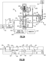
fluid flow system 20 is illustrated inFigure 1A at a shutoff position. Afuel pump 22 communicates with atank 53.Fuel pump 22 supplies fuel to aheat exchanger 149. Aconnection 406 supplies hot oil to theheat exchanger 149 to be cooled by the fuel and then back throughconnection 407 to a use. Afirst branch 145 downstream of theheat exchanger 149 passes through enginefuel metering valve 146 to acombustor 147 in an associated gas turbine engine. A second branch enters into aconnection 24 heading to ametering valve 26.Metering valve 26 has ahousing 28 including fluid ports and a movingspool 30. Thehousing 28 has amain inlet port 32 and afailsafe port 33. Fluid communicates from these ports into aninterior 19 of thespool 30, and to anoutlet orifice 58 in thespool 30. Fluid passes through the spool valve into anoutlet port 40 inhousing 28 and into aline 42 and to a minimum pressure/shutoff valve 43. Atap 45 communicates fluid fromline 42 into aline 48 communicating back with aport 50 in thehousing 28. Aspring 148 biases apiston 44 to close off the supply ofline 42 to aconnection 52 leading to a use for the fluid. The use may befuel tank 53. Aforward face 47 of thepiston 44 sees the pressure from theline 42 and arear chamber 49 sees the pressure from theline 48 and a bias force fromspring 148. In theFigure 1A position, the fluid pressure at theface 47 is essentially the same as that at 48, and thus thespring 148 holds thepiston 44 in this closed position. - As the speed of the engine increases a greater amount of fuel is supplied to the
combustor 147 through theline 145. Thus, the shutoff position ofFigure 1A may be utilized. No fuel will pass through theconnection 24 under such conditions. As the speed of the engine slows less fuel is required to be delivered to thecombustor 147. However, the heat load on the engine, and thus theheat exchanger 149 remain high, and thus it would be desirable to have increased fuel flow into theconnection 24. For this reason, themetering valve 26 has a metering position (seeFigures 3A and 3B ) and the shutoff position (seeFigures 1A and 1B ). - Valve 26 is shown at the
Figure 1A position inFigure 1B . Thehousing 28 has theport 50, themain inlet port 32 andoutlet port 40 all shown in a position where they are closed by an outerperipheral surface 54 of thevalve spool 30. In addition, aseal 100 closesport 50. No fluid communicates withorifices main inlet port 32 is larger thanfailsafe port 33. - The
Figure 1A position may be utilized in this application when the main fuel supply to the combustor is large such as at high power operation. Under such conditions, recirculation of fuel to thefuel tank 53 may not be needed. - Control fluid from
line 61 is passed to achamber 65 on one side of thespool 30 and fluid from anothersource 59 passes into achamber 67 on an opposed side of the spool to move the spool to a desired position. Acontrol 200, shown schematically, selectively controls the supply of fluid to these chambers. - The
control 200 communicates with a control for the overall engine, which may be a full authority digital electric control ("FADEC"). The FADEC would instruct thecontroller 200 to position themetering valve 26 such that when there is a high volume flow of fuel to thecombustor 147, themetering valve 26 may be in the closed position ofFigure 1A . However, at low volume flow to thecombustor 147 thecontrol 200 may move the metering valve to meter fuel across themetering valve 26 and back to thefuel tank 53. This ensures an adequate volume of fuel flowing through theheat exchanger 149. Thecontrol 200 can accurately position themetering valve 26 at the metering positions ofFigure 3A and 3B at an infinite number of positions, including a full flow position. - In shutoff position of
Figure 1A , one can see that thespool 30 is at a mid-stroke position. That is, afirst end 401 of thespool 30 is spaced from afirst shoulder 400 of thehousing 28, providing thechamber 67. Further, asecond end 403 of thespool 30 is spaced from asecond shoulder 402 of thehousing 28, providing thechamber 65. In the prior art, the shutoff position is typically at one of the end of stroke positions wherein one of the first or second ends 401 or 403 would be bottomed out on theshoulder end 401 of thespool 30 is defined to not include atransducer 800 which extends from thefirst end 401. Because the shutoff position is mid-stroke, minimum-stroke and maximum-stroke failsafe positions can be defined as shown inFigures 2A/2B /2C/2D , and as described below. -
Figure 2A shows a minimum-stroke failsafe flow position. This position might occur if thecontrol 200 fails such that the pressure incavity 65 is always greater than the pressure incavity 67. The spool is biased to a position at whichfirst end 401 bottoms out onfirst shoulder 400 due to the presence of pressurized fluid in thechamber 65. This may occur should thecontrol 200 fail, and there is a desire to supply a failsafe fluid flow such that sufficient fluid continues to flow from the heat exchanger. Now, themain inlet port 32 is still closed, but afailsafe port 33 is aligned with the failsafe orifice/metering outlet orifice 57 (it is also aligned inFigure 1B , but the fluid cannot get to the outlet port 40). In this position, fluid from thesource 22 can pass into the failsafe orifice/metering outlet orifice 57 and outwardly of theoutlet port 40 through thefailsafe outlet orifice 58. This flow then reaches the minimum pressure/shutoff valve 43. - If the
connections Figure 1A , the minimum pressure/shutoff valve 43 would still be biased closed. However, in theFigure 2A/2B position one can see that theport 50, which "sees" the pressure fromline 42, is now communicating throughpassage 62 and back intoline 63. Thus, the pressure in thechamber 49 is effectively a lower pressure than that on theface 47. This allows the minimum pressure/shutoff valve 43 to movepiston 44 to an open position. -
Figures 2C and 2D show a maximum-stroke failsafe flow position at which theorifice 56 communicates with thefailsafe port 33, and theorifice 57 communicates with theoutlet port 40. As can be seen,connection 50 still communicates to line 63, such that the minimum flow/shutoff valve 43 allows the minimum flow. This position might occur if thecontrol 200 fails such that the pressure incavity 67 is always greater than the pressure incavity 65.End 403 of thespool 30 bottoms out on thesecond shoulder 402 of thehousing 28. -
Figure 3A shows a full open fluid metering position. In this position fluid passes through themain inlet port 32, through themetering inlet orifice 56, and then through the failsafe orifice/metering outlet orifice 57 to theoutlet port 40.Spool 30 has aninternal cavity 19 connectingmetering inlet orifice 56 to themetering outlet orifice 57. This is a fuel metering position which will be utilized to provide a desired amount of fuel during operation of the engine. -
Figure 3B shows an intermediate metering position. -
Figure 3C shows that the timing between the two metering orifices opening occurs simultaneously. Thus, this is the beginning of metering flow. - In one embodiment, Applicant has recognized that it would be desirable to split a pressure drop across the metering valve between serial metering ports. Thus, this is the beginning of metering flow.
- The disclosed system can operate at very high pressures, and pressures over say 2000 psi. At such high pressures, a large pressure drop across a single metering orifice could result in cavitation. Thus, in a feature of this disclosure, the two
metering orifices 32/56 and 57/40 each provide pressure drop and metering. Thus, the pressure drop may be split between the two. Notably, when themetering inlet orifice 56 initially becomes open to themain inlet port 32, the failsafe orifice/metering outlet orifice 57 is also initially becoming open to theoutlet port 40. - The pressure drops across the
metering orifices 32/56 and 57/40 act in combination with the minimum pressure/shutoff valve 43 to reduce cavitation. As thevalve 43 begins to open, a certain amount of pressure is required to overcome the spring force ofspring 148, and open thepiston 44. This increases the pressure on theface 47 of thepiston 44, and thus the pressure to the outlet of themetering valve 26. In embodiments, a pressure drop ratio can be defined across each of the pairs oforifices 32/56 and 57/40. A pressure drop ratio is defined as: PDR = (Pbefore_window - Pafter_window )/Pafter_window. - In embodiments, the pressure drop ratio across the two pairs of orifices may be equal, although the ratios may also be different.
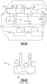
- As shown in
Figure 3D , priorart metering valve 110 had aspool 112 movable within ahousing 113, to meter fuel between aninlet 111 and anoutlet 114. As is clear, there is asingle port 116 connecting theinlet 111 to theoutlet 114. In contrast the disclosed spool hasinternal cavity 19 betweenorifices - In embodiments, the two metering orifices can provide different amounts of pressure drop, but they will both provide pressure drop in embodiments of this disclosure. Aspects of this disclosure may be better understood from co-pending
United States Patent Application No. 17/408183 , entitled "Serial Metering Orifices For A Metering Valve," filed on even date herewith and owned by the Applicant for the instant application. -
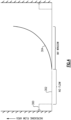
Figure 4 is a plot of example relative fluid flows at the three conditions.Level 300 is the volume of fluid flow in theFigure 2A/2B /2C/2D position.Level 302 is what occurs during the shutoff position ofFigures 1A and 1B . The increasingamount level 304 is what occurs during metering operation ofFigure 3A-3C . - A fluid flow system under this disclosure includes a metering valve having a housing including a main inlet port and a failsafe inlet port. A spool is movable within the housing. There is a second supply port through the housing and a metering valve outlet line from the housing connected to a line leading to a shutoff valve. The second supply line communicates to a rear chamber of a piston in the shutoff valve, and to the metering valve outlet line. The shutoff valve has a spring urging the piston to a closed position at which it blocks flow from the metering valve outlet line from reaching an outlet to a use. The spool is movable between a shutoff position at which it blocks flow from the main inlet port and the failsafe inlet port from reaching the metering valve outlet line, and blocks flow from the second supply line from moving into the spool, such that the shutoff valve is biased to a shutoff position. The metering valve also is movable to a metering position at which the main inlet port and a main inlet orifice in the spool are aligned. An outlet orifice in the spool is aligned with a main outlet port in the housing such that fluid can be metered to the shutoff valve and passed downstream to the use. The spool has a first end and a second end. The housing has a first shoulder associated with the first end and a second shoulder associated with the second end. In the shutoff position, the spool has the first end spaced from the first shoulder, and the second end spaced from the second shoulder. The control chambers are defined between each of the first and second ends and each of the first and second shoulders. The metering valve has a first failsafe position at which the first end bottoms out on the first shoulder and the failsafe port communicates a limited amount of fluid to the metering valve outlet line, and to the shutoff valve.
- The second supply line is communicated to a line passing downstream to the use such that the pressure on the rear chamber of the shutoff valve is lower than the pressure on a front face of the piston. The shutoff valve will allow flow to the line leading to the use. The metering valve also has a second failsafe position which the second end bottoms out on the second shoulder. The failsafe inlet orifice communicates a limited amount of fluid to the metering valve outlet line and to the shutoff valve. Again, the pressure on the rear chamber of the shutoff valve is lower than the pressure on a front face of the piston and the shutoff valve will allow flow to the line leading to the use.
- At the first failsafe position, the failsafe inlet communicates with the main outlet orifice in the spool. At the second failsafe position, the failsafe inlet port communicates with the main inlet orifice.
- Although embodiments of this disclosure have been shown, a worker of ordinary skill in this art would recognize that modifications would come within the scope of this disclosure. For that reason, the following claims should be studied to determine the true scope and content of this disclosure.
Claims (13)
- A fluid flow system comprising:a shutoff valve (43) comprising a spring, a piston and a rear chamber of the piston, and;a metering valve (26) having a housing (28) including a main inlet port (32) and a failsafe inlet port (33) and a spool (30) movable within the housing, and there being a second supply port through the housing and a metering valve outlet line from the housing connected to a line leading to the shutoff valve (43), a second supply line communicating to the rear chamber (49) of the piston (44) in the shutoff valve, and to the metering valve outlet line, and the shutoff valve having the spring (148) urging the piston to a closed position at which it blocks flow from the metering valve outlet line from reaching an outlet to a use, with the spool (30) being movable to a shutoff position at which it blocks flow from the main inlet port and the failsafe inlet port from reaching the metering valve outlet line, and blocks flow from the second supply line from moving into the spool (30), such that the shutoff valve (43) is biased to a shutoff position, the metering valve (26) also being movable to a metering position at which the main inlet port and a main inlet orifice in the spool are aligned, and an outlet orifice in the spool is aligned with a main outlet port in the housing such that fluid can be metered to the shutoff valve and passed downstream to the use;the spool (30) having a first end (401) and a second end (403), and the housing having a first shoulder (400) associated with the first end and a second shoulder (402) associated with the second end, and in the shutoff position the spool (30) having the first end (401) spaced from the first shoulder (400), and the second end (403) spaced from the second shoulder (402), such that control chambers are defined between each of the first and second ends and each of the first and second shoulders, and characterized in that;the metering valve (26) having a first failsafe position at which the first end (401) bottoms out on the first shoulder (400) and the failsafe inlet port communicates a limited amount of fluid to the metering valve outlet line, and to the shutoff valve (43), and the second supply line being communicated to a line passing downstream to the use such that the pressure on the rear chamber of the shutoff valve (43) is lower than the pressure on a front face of the piston (44), and the shutoff valve (43) will allow flow to the line leading to the use, the metering valve (26) also having a second failsafe position at which the second end (403) bottoms out on the second shoulder (402), and the failsafe inlet port communicates a limited amount of fluid to the metering valve outlet line and to the shutoff valve (43) and the second supply line being communicated to the line passing downstream to the use such that the pressure on the rear chamber of the shutoff valve (43) is lower than the pressure on a front face of the piston (44) and the shutoff valve (43) will allow flow to the line leading to the use.
- The fluid flow system as set forth in claim 1, wherein the main inlet port (32) in the housing is larger than the failsafe inlet port (33) in the housing.
- The fluid flow system as set forth in claim 1, wherein a control (200) selectively applies pressurized fluid to a first control chamber defined between first end (401) and the first shoulder (400) and to a second control chamber between the second end (403) and second shoulder (402), and the first failsafe position is taken when the control fails and no longer supplies pressurized fluid to the said first control chamber, and the second failsafe position is taken when the control fails and no longer supplies pressurized fluid to the second control chamber between the second end (403) and second shoulder (402).
- The fluid flow system as set forth in claim 3, wherein a seal (100) provided in the spool (30) is aligned with the second supply line in the closed position.
- The fluid flow system as set forth in claim 3, wherein the use is to meter fuel from a heat exchanger.
- The fluid flow system as set forth in claim 1, wherein at the first failsafe position the failsafe inlet communicates with the main outlet orifice in the spool (30), and at the second failsafe position the failsafe inlet port communicating with the main inlet orifice; and/or wherein a seal (100) provided in the spool is aligned with the second supply line in the closed position; and/or wherein at the first failsafe position the failsafe inlet communicates with the main outlet orifice in the spool (30), and at the second failsafe position the failsafe inlet port communicating with the main inlet orifice.
- The fluid flow system as set forth in claim 1, wherein a seal (100) provided in the spool is aligned with the second supply line in the closed position.
- A fuel system for a gas turbine engine comprising:the fluid flow system of claim 1;a fuel pump (22) delivering fuel from a fuel tank to a heat exchanger (149);a fluid line downstream of the heat exchanger (149) to communicate the fuel to a first branch (145) leading to an engine metering valve to meter fuel heading to a combustor (147) for a gas turbine engine, and a second branch leading into the fluid flow system, wherein the second branch leads to the inlet port on the metering valve (26).
- The fuel system as set forth in claim 8, wherein the main inlet port (32) in the housing is larger than the failsafe inlet port (33) in the housing.
- The fuel system as set forth in claim 8, wherein a control (200) selectively applies pressurized fluid to a first said control chamber defined between first end (401) and the first shoulder (400) and to a second said control chamber between the second end (403) and second control chamber, and the first failsafe position is taken when the control fails and no longer supplies pressurized fluid to the said first control chamber, and the second failsafe position is taken when the control fails and no longer supplies pressurized fluid to the second control chamber between the second end (403) and second shoulder (402) .
- The fuel system as set forth in claim 10, wherein a seal (100) provided in the spool valve is aligned with the second supply line in the closed position; and/or wherein the use is to meter fuel from the heat exchanger.
- The fuel system as set forth in claim 8, wherein at the first failsafe position the failsafe inlet communicates with the main outlet orifice in the spool, and at the second failsafe position the failsafe inlet port communicating with the main inlet orifice; and/or wherein a seal (100) provided in the spool valve is aligned with the second supply line in the closed position; and/or wherein at the first failsafe position the failsafe inlet communicates with the main outlet orifice in the spool, and at the second failsafe position the failsafe inlet port (33) communicating with the main inlet orifice.
- The fuel system as set forth in claim 8, wherein a seal (100) provided in the spool valve is aligned with the second supply line in the closed position.
Applications Claiming Priority (1)
| Application Number | Priority Date | Filing Date | Title |
|---|---|---|---|
| US17/408,212 US11703134B2 (en) | 2021-08-20 | 2021-08-20 | Metering valve with mid-stroke shutoff |
Publications (2)
| Publication Number | Publication Date |
|---|---|
| EP4141237A1 EP4141237A1 (en) | 2023-03-01 |
| EP4141237B1 true EP4141237B1 (en) | 2024-11-13 |
Family
ID=82939878
Family Applications (1)
| Application Number | Title | Priority Date | Filing Date |
|---|---|---|---|
| EP22190597.9A Active EP4141237B1 (en) | 2021-08-20 | 2022-08-16 | Metering valve with mid-stroke shutoff |
Country Status (2)
| Country | Link |
|---|---|
| US (1) | US11703134B2 (en) |
| EP (1) | EP4141237B1 (en) |
Families Citing this family (1)
| Publication number | Priority date | Publication date | Assignee | Title |
|---|---|---|---|---|
| IT202100014258A1 (en) * | 2021-05-31 | 2022-12-01 | Ivar Spa | APPARATUS AND METHOD FOR THE REGULATION AND BALANCING OF A THERMAL SYSTEM |
Family Cites Families (17)
| Publication number | Priority date | Publication date | Assignee | Title |
|---|---|---|---|---|
| US3638885A (en) | 1970-03-09 | 1972-02-01 | Boeing Co | Lag frequency selective damper |
| DE3521193A1 (en) | 1985-06-13 | 1986-12-18 | MTU Motoren- und Turbinen-Union München GmbH, 8000 München | FUEL CONTROL DEVICE OF A GAS TURBINE ENGINE WITH A COMBINED PRESSURE BUILDING, DRAINAGE AND SHUT-OFF VALVE |
| US4751942A (en) * | 1987-04-24 | 1988-06-21 | United Technologies Corporation | Multi-function fuel metering valve |
| US5448882A (en) | 1993-12-14 | 1995-09-12 | United Technologies Corporation | Fuel metering system |
| US5433237A (en) | 1994-07-11 | 1995-07-18 | Woodward Governor Company | Dedrooped bypass valve |
| US5772182A (en) | 1996-04-17 | 1998-06-30 | United Technologies Corporation | Fuel flow control valve |
| JP3679300B2 (en) | 1999-06-10 | 2005-08-03 | 日立建機株式会社 | Volume control valve for variable displacement hydraulic rotating machine |
| US6314998B1 (en) | 1999-07-27 | 2001-11-13 | Alliedsignal Inc. | Fuel divider and ecology system for a gas turbine engine |
| US6390129B2 (en) | 1999-12-15 | 2002-05-21 | Jansen's Aircraft Systems Controls, Inc. | Proportional solenoid-operated fluid metering device |
| US6401446B1 (en) | 2000-06-23 | 2002-06-11 | Hamilton Sundstrand Corporation | Valve apparatus for providing shutoff and overspeed protection in a gas turbine fuel system |
| US20020184884A1 (en) | 2001-06-08 | 2002-12-12 | Honeywell International, Inc. | Rapid shutdown and ecology system |
| US6981359B2 (en) | 2003-06-16 | 2006-01-03 | Woodward Governor Company | Centrifugal pump fuel system and method for gas turbine engine |
| FR2923871B1 (en) | 2007-11-19 | 2013-11-08 | Hispano Suiza Sa | MONITORING A HIGH PRESSURE PUMP IN A FUEL SUPPLY CIRCUIT OF A TURBOMACHINE. |
| GB0905710D0 (en) | 2009-04-02 | 2009-05-20 | Rolls Royce Goodrich Engine Co | Staging valve |
| US9399953B2 (en) | 2012-09-19 | 2016-07-26 | Hamilton Sundstrand Corporation | Gas turbine engine fuel system pump sharing valve |
| US9212608B2 (en) * | 2013-05-24 | 2015-12-15 | Hamilton Sundstrand Corporation | Low friction fuel metering valve |
| US10309312B2 (en) | 2015-07-21 | 2019-06-04 | Safran Aircraft Engines | Fuel metering device protected against icing |
-
2021
- 2021-08-20 US US17/408,212 patent/US11703134B2/en active Active
-
2022
- 2022-08-16 EP EP22190597.9A patent/EP4141237B1/en active Active
Also Published As
| Publication number | Publication date |
|---|---|
| US20230058118A1 (en) | 2023-02-23 |
| US11703134B2 (en) | 2023-07-18 |
| EP4141237A1 (en) | 2023-03-01 |
Similar Documents
| Publication | Publication Date | Title |
|---|---|---|
| EP2497923B1 (en) | Fuel system | |
| US8887752B2 (en) | Fuel staging system | |
| US8291707B2 (en) | Multi-stage check valve | |
| EP1344916B1 (en) | Fuel system | |
| JP5666604B2 (en) | Fuel supply circuit for aero engines | |
| EP2744996B1 (en) | Split control unit | |
| CA2756846C (en) | Flow sensing shutoff valve | |
| EP2390484B1 (en) | Fuel pumping system for a gas turbine engine | |
| EP4063633B1 (en) | Fuel supply system with combined metering and shutoff valve | |
| EP2321520B1 (en) | Flow compensated proportional bypass valve combined with a control valve | |
| EP0915241A2 (en) | Fuel flow shut-off system | |
| WO2008016435A1 (en) | Multi-stage relief valve having different opening pressures | |
| US20140076435A1 (en) | Gas turbine engine fuel system pump sharing valve | |
| EP4141237B1 (en) | Metering valve with mid-stroke shutoff | |
| EP4137691A1 (en) | Serial metering orifices for a metering valve | |
| CN103244278A (en) | Gas turbine engine fuel return valve and system | |
| EP2175119B1 (en) | Combined metering valve and pressure regulating valve | |
| GB2320063A (en) | Fuel staging system for gas turbine engine | |
| US12398720B2 (en) | Direct controlled variable displacement valves with dual set point pressure relief | |
| GB1112481A (en) | Fuel supply systems for jet propulsion engines | |
| EP4183995B1 (en) | Hydraulically rate limited valve | |
| EP4495425A1 (en) | Combined high pressure relief and bypass valves | |
| EP1735529B1 (en) | Method and apparatus generating multiple pressure signals in a fuel system | |
| GB2432886A (en) | Gas turbine engine reheat fuel control system and control valves therefor |
Legal Events
| Date | Code | Title | Description |
|---|---|---|---|
| PUAI | Public reference made under article 153(3) epc to a published international application that has entered the european phase |
Free format text: ORIGINAL CODE: 0009012 |
|
| STAA | Information on the status of an ep patent application or granted ep patent |
Free format text: STATUS: THE APPLICATION HAS BEEN PUBLISHED |
|
| AK | Designated contracting states |
Kind code of ref document: A1 Designated state(s): AL AT BE BG CH CY CZ DE DK EE ES FI FR GB GR HR HU IE IS IT LI LT LU LV MC MK MT NL NO PL PT RO RS SE SI SK SM TR |
|
| STAA | Information on the status of an ep patent application or granted ep patent |
Free format text: STATUS: REQUEST FOR EXAMINATION WAS MADE |
|
| 17P | Request for examination filed |
Effective date: 20230831 |
|
| RBV | Designated contracting states (corrected) |
Designated state(s): AL AT BE BG CH CY CZ DE DK EE ES FI FR GB GR HR HU IE IS IT LI LT LU LV MC MK MT NL NO PL PT RO RS SE SI SK SM TR |
|
| GRAP | Despatch of communication of intention to grant a patent |
Free format text: ORIGINAL CODE: EPIDOSNIGR1 |
|
| STAA | Information on the status of an ep patent application or granted ep patent |
Free format text: STATUS: GRANT OF PATENT IS INTENDED |
|
| INTG | Intention to grant announced |
Effective date: 20240621 |
|
| GRAS | Grant fee paid |
Free format text: ORIGINAL CODE: EPIDOSNIGR3 |
|
| GRAA | (expected) grant |
Free format text: ORIGINAL CODE: 0009210 |
|
| STAA | Information on the status of an ep patent application or granted ep patent |
Free format text: STATUS: THE PATENT HAS BEEN GRANTED |
|
| AK | Designated contracting states |
Kind code of ref document: B1 Designated state(s): AL AT BE BG CH CY CZ DE DK EE ES FI FR GB GR HR HU IE IS IT LI LT LU LV MC MK MT NL NO PL PT RO RS SE SI SK SM TR |
|
| REG | Reference to a national code |
Ref country code: GB Ref legal event code: FG4D |
|
| REG | Reference to a national code |
Ref country code: CH Ref legal event code: EP |
|
| REG | Reference to a national code |
Ref country code: DE Ref legal event code: R096 Ref document number: 602022007658 Country of ref document: DE |
|
| REG | Reference to a national code |
Ref country code: IE Ref legal event code: FG4D |
|
| REG | Reference to a national code |
Ref country code: LT Ref legal event code: MG9D |
|
| REG | Reference to a national code |
Ref country code: NL Ref legal event code: MP Effective date: 20241113 |
|
| PG25 | Lapsed in a contracting state [announced via postgrant information from national office to epo] |
Ref country code: HR Free format text: LAPSE BECAUSE OF FAILURE TO SUBMIT A TRANSLATION OF THE DESCRIPTION OR TO PAY THE FEE WITHIN THE PRESCRIBED TIME-LIMIT Effective date: 20241113 Ref country code: IS Free format text: LAPSE BECAUSE OF FAILURE TO SUBMIT A TRANSLATION OF THE DESCRIPTION OR TO PAY THE FEE WITHIN THE PRESCRIBED TIME-LIMIT Effective date: 20250313 Ref country code: PT Free format text: LAPSE BECAUSE OF FAILURE TO SUBMIT A TRANSLATION OF THE DESCRIPTION OR TO PAY THE FEE WITHIN THE PRESCRIBED TIME-LIMIT Effective date: 20250313 |
|
| PG25 | Lapsed in a contracting state [announced via postgrant information from national office to epo] |
Ref country code: FI Free format text: LAPSE BECAUSE OF FAILURE TO SUBMIT A TRANSLATION OF THE DESCRIPTION OR TO PAY THE FEE WITHIN THE PRESCRIBED TIME-LIMIT Effective date: 20241113 Ref country code: NL Free format text: LAPSE BECAUSE OF FAILURE TO SUBMIT A TRANSLATION OF THE DESCRIPTION OR TO PAY THE FEE WITHIN THE PRESCRIBED TIME-LIMIT Effective date: 20241113 |
|
| REG | Reference to a national code |
Ref country code: AT Ref legal event code: MK05 Ref document number: 1741846 Country of ref document: AT Kind code of ref document: T Effective date: 20241113 |
|
| PG25 | Lapsed in a contracting state [announced via postgrant information from national office to epo] |
Ref country code: BG Free format text: LAPSE BECAUSE OF FAILURE TO SUBMIT A TRANSLATION OF THE DESCRIPTION OR TO PAY THE FEE WITHIN THE PRESCRIBED TIME-LIMIT Effective date: 20241113 |
|
| PG25 | Lapsed in a contracting state [announced via postgrant information from national office to epo] |
Ref country code: ES Free format text: LAPSE BECAUSE OF FAILURE TO SUBMIT A TRANSLATION OF THE DESCRIPTION OR TO PAY THE FEE WITHIN THE PRESCRIBED TIME-LIMIT Effective date: 20241113 |
|
| PG25 | Lapsed in a contracting state [announced via postgrant information from national office to epo] |
Ref country code: NO Free format text: LAPSE BECAUSE OF FAILURE TO SUBMIT A TRANSLATION OF THE DESCRIPTION OR TO PAY THE FEE WITHIN THE PRESCRIBED TIME-LIMIT Effective date: 20250213 |
|
| PG25 | Lapsed in a contracting state [announced via postgrant information from national office to epo] |
Ref country code: AT Free format text: LAPSE BECAUSE OF FAILURE TO SUBMIT A TRANSLATION OF THE DESCRIPTION OR TO PAY THE FEE WITHIN THE PRESCRIBED TIME-LIMIT Effective date: 20241113 Ref country code: LV Free format text: LAPSE BECAUSE OF FAILURE TO SUBMIT A TRANSLATION OF THE DESCRIPTION OR TO PAY THE FEE WITHIN THE PRESCRIBED TIME-LIMIT Effective date: 20241113 Ref country code: GR Free format text: LAPSE BECAUSE OF FAILURE TO SUBMIT A TRANSLATION OF THE DESCRIPTION OR TO PAY THE FEE WITHIN THE PRESCRIBED TIME-LIMIT Effective date: 20250214 |
|
| PG25 | Lapsed in a contracting state [announced via postgrant information from national office to epo] |
Ref country code: PL Free format text: LAPSE BECAUSE OF FAILURE TO SUBMIT A TRANSLATION OF THE DESCRIPTION OR TO PAY THE FEE WITHIN THE PRESCRIBED TIME-LIMIT Effective date: 20241113 |
|
| PG25 | Lapsed in a contracting state [announced via postgrant information from national office to epo] |
Ref country code: RS Free format text: LAPSE BECAUSE OF FAILURE TO SUBMIT A TRANSLATION OF THE DESCRIPTION OR TO PAY THE FEE WITHIN THE PRESCRIBED TIME-LIMIT Effective date: 20250213 |
|
| PG25 | Lapsed in a contracting state [announced via postgrant information from national office to epo] |
Ref country code: SM Free format text: LAPSE BECAUSE OF FAILURE TO SUBMIT A TRANSLATION OF THE DESCRIPTION OR TO PAY THE FEE WITHIN THE PRESCRIBED TIME-LIMIT Effective date: 20241113 |
|
| PG25 | Lapsed in a contracting state [announced via postgrant information from national office to epo] |
Ref country code: DK Free format text: LAPSE BECAUSE OF FAILURE TO SUBMIT A TRANSLATION OF THE DESCRIPTION OR TO PAY THE FEE WITHIN THE PRESCRIBED TIME-LIMIT Effective date: 20241113 |
|
| PG25 | Lapsed in a contracting state [announced via postgrant information from national office to epo] |
Ref country code: EE Free format text: LAPSE BECAUSE OF FAILURE TO SUBMIT A TRANSLATION OF THE DESCRIPTION OR TO PAY THE FEE WITHIN THE PRESCRIBED TIME-LIMIT Effective date: 20241113 |
|
| PG25 | Lapsed in a contracting state [announced via postgrant information from national office to epo] |
Ref country code: RO Free format text: LAPSE BECAUSE OF FAILURE TO SUBMIT A TRANSLATION OF THE DESCRIPTION OR TO PAY THE FEE WITHIN THE PRESCRIBED TIME-LIMIT Effective date: 20241113 |
|
| PG25 | Lapsed in a contracting state [announced via postgrant information from national office to epo] |
Ref country code: SK Free format text: LAPSE BECAUSE OF FAILURE TO SUBMIT A TRANSLATION OF THE DESCRIPTION OR TO PAY THE FEE WITHIN THE PRESCRIBED TIME-LIMIT Effective date: 20241113 |
|
| PG25 | Lapsed in a contracting state [announced via postgrant information from national office to epo] |
Ref country code: CZ Free format text: LAPSE BECAUSE OF FAILURE TO SUBMIT A TRANSLATION OF THE DESCRIPTION OR TO PAY THE FEE WITHIN THE PRESCRIBED TIME-LIMIT Effective date: 20241113 |
|
| PG25 | Lapsed in a contracting state [announced via postgrant information from national office to epo] |
Ref country code: IT Free format text: LAPSE BECAUSE OF FAILURE TO SUBMIT A TRANSLATION OF THE DESCRIPTION OR TO PAY THE FEE WITHIN THE PRESCRIBED TIME-LIMIT Effective date: 20241113 |
|
| REG | Reference to a national code |
Ref country code: DE Ref legal event code: R097 Ref document number: 602022007658 Country of ref document: DE |
|
| PG25 | Lapsed in a contracting state [announced via postgrant information from national office to epo] |
Ref country code: SE Free format text: LAPSE BECAUSE OF FAILURE TO SUBMIT A TRANSLATION OF THE DESCRIPTION OR TO PAY THE FEE WITHIN THE PRESCRIBED TIME-LIMIT Effective date: 20241113 |
|
| PLBE | No opposition filed within time limit |
Free format text: ORIGINAL CODE: 0009261 |
|
| STAA | Information on the status of an ep patent application or granted ep patent |
Free format text: STATUS: NO OPPOSITION FILED WITHIN TIME LIMIT |
|
| PGFP | Annual fee paid to national office [announced via postgrant information from national office to epo] |
Ref country code: DE Payment date: 20250724 Year of fee payment: 4 |
|
| PGFP | Annual fee paid to national office [announced via postgrant information from national office to epo] |
Ref country code: FR Payment date: 20250723 Year of fee payment: 4 |
|
| 26N | No opposition filed |
Effective date: 20250814 |