EP4140940B1 - Getränkevorrichtungen, -systeme und -verfahren - Google Patents
Getränkevorrichtungen, -systeme und -verfahren Download PDFInfo
- Publication number
- EP4140940B1 EP4140940B1 EP22191515.0A EP22191515A EP4140940B1 EP 4140940 B1 EP4140940 B1 EP 4140940B1 EP 22191515 A EP22191515 A EP 22191515A EP 4140940 B1 EP4140940 B1 EP 4140940B1
- Authority
- EP
- European Patent Office
- Prior art keywords
- valve
- controller
- vessel
- various embodiments
- pump
- Prior art date
- Legal status (The legal status is an assumption and is not a legal conclusion. Google has not performed a legal analysis and makes no representation as to the accuracy of the status listed.)
- Active
Links
Images




Classifications
-
- B—PERFORMING OPERATIONS; TRANSPORTING
- B67—OPENING, CLOSING OR CLEANING BOTTLES, JARS OR SIMILAR CONTAINERS; LIQUID HANDLING
- B67D—DISPENSING, DELIVERING OR TRANSFERRING LIQUIDS, NOT OTHERWISE PROVIDED FOR
- B67D1/00—Apparatus or devices for dispensing beverages on draught
- B67D1/08—Details
- B67D1/0878—Safety, warning or controlling devices
- B67D1/0882—Devices for controlling the dispensing conditions
- B67D1/0884—Means for controlling the parameters of the state of the liquid to be dispensed, e.g. temperature, pressure
-
- B—PERFORMING OPERATIONS; TRANSPORTING
- B67—OPENING, CLOSING OR CLEANING BOTTLES, JARS OR SIMILAR CONTAINERS; LIQUID HANDLING
- B67D—DISPENSING, DELIVERING OR TRANSFERRING LIQUIDS, NOT OTHERWISE PROVIDED FOR
- B67D1/00—Apparatus or devices for dispensing beverages on draught
- B67D1/0042—Details of specific parts of the dispensers
- B67D1/0057—Carbonators
- B67D1/0069—Details
- B67D1/007—Structure of the carbonating chamber
-
- B—PERFORMING OPERATIONS; TRANSPORTING
- B67—OPENING, CLOSING OR CLEANING BOTTLES, JARS OR SIMILAR CONTAINERS; LIQUID HANDLING
- B67D—DISPENSING, DELIVERING OR TRANSFERRING LIQUIDS, NOT OTHERWISE PROVIDED FOR
- B67D1/00—Apparatus or devices for dispensing beverages on draught
- B67D1/0015—Apparatus or devices for dispensing beverages on draught the beverage being prepared by mixing at least two liquid components
- B67D1/0021—Apparatus or devices for dispensing beverages on draught the beverage being prepared by mixing at least two liquid components the components being mixed at the time of dispensing, i.e. post-mix dispensers
- B67D1/0022—Apparatus or devices for dispensing beverages on draught the beverage being prepared by mixing at least two liquid components the components being mixed at the time of dispensing, i.e. post-mix dispensers the apparatus comprising means for automatically controlling the amount to be dispensed
- B67D1/0023—Apparatus or devices for dispensing beverages on draught the beverage being prepared by mixing at least two liquid components the components being mixed at the time of dispensing, i.e. post-mix dispensers the apparatus comprising means for automatically controlling the amount to be dispensed control of the amount of the mixture, i.e. after mixing
-
- B—PERFORMING OPERATIONS; TRANSPORTING
- B67—OPENING, CLOSING OR CLEANING BOTTLES, JARS OR SIMILAR CONTAINERS; LIQUID HANDLING
- B67D—DISPENSING, DELIVERING OR TRANSFERRING LIQUIDS, NOT OTHERWISE PROVIDED FOR
- B67D1/00—Apparatus or devices for dispensing beverages on draught
- B67D1/0042—Details of specific parts of the dispensers
- B67D1/0043—Mixing devices for liquids
- B67D1/0044—Mixing devices for liquids for mixing inside the dispensing nozzle
- B67D1/0046—Mixing chambers
-
- B—PERFORMING OPERATIONS; TRANSPORTING
- B67—OPENING, CLOSING OR CLEANING BOTTLES, JARS OR SIMILAR CONTAINERS; LIQUID HANDLING
- B67D—DISPENSING, DELIVERING OR TRANSFERRING LIQUIDS, NOT OTHERWISE PROVIDED FOR
- B67D1/00—Apparatus or devices for dispensing beverages on draught
- B67D1/0042—Details of specific parts of the dispensers
- B67D1/0057—Carbonators
- B67D1/0069—Details
- B67D1/0074—Automatic carbonation control
-
- B—PERFORMING OPERATIONS; TRANSPORTING
- B67—OPENING, CLOSING OR CLEANING BOTTLES, JARS OR SIMILAR CONTAINERS; LIQUID HANDLING
- B67D—DISPENSING, DELIVERING OR TRANSFERRING LIQUIDS, NOT OTHERWISE PROVIDED FOR
- B67D1/00—Apparatus or devices for dispensing beverages on draught
- B67D1/08—Details
- B67D1/0888—Means comprising electronic circuitry (e.g. control panels, switching or controlling means)
-
- B—PERFORMING OPERATIONS; TRANSPORTING
- B67—OPENING, CLOSING OR CLEANING BOTTLES, JARS OR SIMILAR CONTAINERS; LIQUID HANDLING
- B67D—DISPENSING, DELIVERING OR TRANSFERRING LIQUIDS, NOT OTHERWISE PROVIDED FOR
- B67D1/00—Apparatus or devices for dispensing beverages on draught
- B67D1/08—Details
- B67D1/12—Flow or pressure control devices or systems, e.g. valves, gas pressure control, level control in storage containers
- B67D1/1252—Gas pressure control means, e.g. for maintaining proper carbonation
-
- B—PERFORMING OPERATIONS; TRANSPORTING
- B67—OPENING, CLOSING OR CLEANING BOTTLES, JARS OR SIMILAR CONTAINERS; LIQUID HANDLING
- B67D—DISPENSING, DELIVERING OR TRANSFERRING LIQUIDS, NOT OTHERWISE PROVIDED FOR
- B67D2210/00—Indexing scheme relating to aspects and details of apparatus or devices for dispensing beverages on draught or for controlling flow of liquids under gravity from storage containers for dispensing purposes
- B67D2210/00028—Constructional details
- B67D2210/00081—Constructional details related to bartenders
-
- B—PERFORMING OPERATIONS; TRANSPORTING
- B67—OPENING, CLOSING OR CLEANING BOTTLES, JARS OR SIMILAR CONTAINERS; LIQUID HANDLING
- B67D—DISPENSING, DELIVERING OR TRANSFERRING LIQUIDS, NOT OTHERWISE PROVIDED FOR
- B67D2210/00—Indexing scheme relating to aspects and details of apparatus or devices for dispensing beverages on draught or for controlling flow of liquids under gravity from storage containers for dispensing purposes
- B67D2210/00028—Constructional details
- B67D2210/00128—Constructional details relating to outdoor use; movable; portable
- B67D2210/00133—Constructional details relating to outdoor use; movable; portable wheeled
- B67D2210/00139—Trolleys
Definitions
- the present disclosure relates generally to beverage devices, systems, and methods, and, more particularly, to mobile beverage devices systems and methods for use in aircraft cabins.
- US 10336597 B2 discloses a capsule-based alcoholic beverage forming apparatus operable to dispense an alcoholic beverage having a desired flavor, proof, temperature, and volume, which mixes water and alcohol with a flavor medium to form an alcoholic beverage having a desired flavor that may be dispensed from the apparatus.
- WO 2016/178734 A1 discloses juicing systems and methods for preparing custom beverages.
- the beverage mixing device may comprise: a housing; a dispensing head spaced apart from the housing; a nozzle coupled to the dispensing head; a capsule receiver configured to receive a capsule including a pre-mixed composition, the capsule receiver including a first sensor; a water supply tank disposed within the housing; a carbonation vessel disposed within the housing, the carbonation vessel configured for on-demand carbonation; and a controller in electronic communication with the first sensor, the controller configured to: determine a drink type based on receiving sensor data from the first sensor, and dispense a carbonated water or a non-carbonated water based the drink type.
- the beverage mixing device may be mobile. It may also be stationary or installed in an aircraft cabin.
- the beverage mixing device may further comprise a pump disposed between the water supply tank and a first valve, the controller further configured to activate the first valve to fluidly couple the water supply tank to the on-demand carbonation vessel in response the controller receiving an indication the drink type uses carbonated water.
- the first valve may comprise a first inlet, a first outlet, and a second outlet.
- a first fluid conduit may extend from the second outlet to a first inlet of a second valve.
- the second valve may include the first inlet, a second inlet in fluid communication with the carbonation vessel, and a first outlet in fluid communication with the nozzle.
- the beverage mixing device may further comprise a flow meter disposed between the water supply tank and the pump, the flow meter in electronic communication with the controller.
- the controller may be further configured to command pumping of water, via the pump, from the water supply tank in response to determining the drink type includes a non-carbonated water for mixing.
- the beverage mixing device may further comprise a third valve disposed between a carbon dioxide vessel and the on-demand carbonation vessel.
- the controller in response to determining the drink type includes a carbonated water, is further configured to: activate the first valve to fluidly couple the water supply tank to the on-demand carbonation vessel, activate the third valve to fluidly couple the carbon dioxide vessel to the on-demand carbonation vessel, and activate the second valve to fluidly couple the on-demand carbonation vessel to the nozzle.
- the article of manufacture may include a tangible, non-transitory computer-readable storage medium having instructions stored thereon that, in response to execution by a processor, cause the processor to perform operations comprising: receiving, via a processor, an identifier from a sensor disposed in a beverage mixing device, the sensor configured to capture the identifier on a capsule including a pre-mixed composition; determining, via the processor, a drink type associated with the identifier; determining, via the processor, the drink type includes a carbonated water; activating, via the processor, a first valve to fluidly couple a water supply tank to an on-demand carbonation vessel; activating, via the processor, a second valve to vent the on-demand carbonation vessel during filling of the on-demand carbonation vessel with water; de-activating, via the processor the first valve and the second valve; activating, via the processor, a third valve to fluidly couple a carbon dioxide vessel to the on-demand carbonation vessel; and activating, via the processor
- the operations may further: comprise receiving, via the processor, pressure data from a pressure transducer disposed between the on-demand carbonation vessel and the third valve.
- the operations may further comprise de-activating the third valve in response to a pressure in the pressure data exceeding a pressure threshold.
- De-activating the first valve and the fourth valve may be in response to determining a predetermined volume of water is disposed in the on-demand carbonation vessel based on data received from a flow meter.
- the operations may further comprise commanding, via the processor, an air pump to pump air through the nozzle.
- the operations may further comprise commanding, via the processor, a pump to pump non-carbonated water from the water supply tank in response to determining the drink type includes a non-carbonated water as a mixer.
- a control system for a beverage mixing device according to the invention is disclosed in claim 13.
- control system may further comprise a carbonation vessel and a pressure transducer configured to measure a pressure in the carbonation vessel.
- the controller may be further configured to receive pressure data from the pressure transducer.
- the control system may be configured to activate the fourth valve while filling the on-demand carbonation vessel with water from the water supply tank.
- the control system may further comprise an air pump configured to be fluidly coupled with a nozzle, the second valve fluidly coupled to the nozzle.
- the controller may further be configured to command the air pump to dispense a pressurized air through the nozzle.
- references to "a,” “an” or “the” may include one or more than one and that reference to an item in the singular may also include the item in the plural. Further, all ranges may include upper and lower values and all ranges and ratio limits disclosed herein may be combined.
- the alcoholic beverage mixing device is mobile. Although described herein as being a mobile device, the present disclosure is not limited in this regard.
- the alcoholic beverage mixing device may be stationary and may be configured to be installed in an aircraft cabin, in accordance with various embodiments.
- the alcoholic beverage mixing device may comprise a power source.
- the power source may be capable of powering the alcoholic beverage mixing device.
- the power source may be a rechargeable power source, such as a battery, auxiliary power units, generators, or the like.
- the alcoholic beverage mixing device comprises a dispensing head, a mixing nozzle, a water supply tank, a carbon dioxide tank, a carbonation vessel, pump(s), and a controller.
- the controller is configured to perform various operations to mix alcohol and generate a mixed alcoholic drink, as described further herein.
- the alcoholic beverage device comprises flavoring concentrates including alcohol.
- alcoholic beverages available in flight are limited to beer, wine, and single serve bottles of distilled spirits (vodka, whiskey, etc.) or liqueur that can be mixed by the customer with another beverage, sometimes referred to as a mixer.
- the devices disclosed herein allow for the sale of more complex cocktails (mixtures of distilled spirits and mixers) like margaritas, mojitos, long island iced teas, and others, in accordance with various embodiments.
- the devices disclosed herein may provide an additional revenue stream from passengers and/or enhanced amenities for various passengers, in accordance with various embodiments.
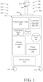
- the device 100, 300, 400, 500 comprises housing 101 configured to house a water supply tank 110, pump(s) 120, a carbonation vessel 130, a controller 102, 302, 402, 502 and a power source 104.
- the housing 101 may be mobile (e.g., the device 100, 300, 400, 500 may include wheel(s) 103 coupled to the housing 101). Although illustrated as including wheel(s) 103, the present disclosure is not limited in this regard.
- the housing 101 may be installed in a cabin of an aircraft, in accordance with various embodiments.
- the device 100, 300, 400, 500 further comprises a dispensing head 150, a nozzle 160, a drip tray 170, and a plumbing system 180, 380, 480, 580.
- the plumbing system 180, 380, 480, 580 may be in fluid communication with the water supply tank 110, the carbonation vessel 130, and the carbon dioxide vessel 140.
- the plumbing system 180, 380, 480, 580 is configured to transport a mixed drink generated from the device 100, 300, 400, 500 through the nozzle 160 via the plumbing system 180, 380, 480, 580 as described further herein.
- the device 100, 300, 400, 500 further comprises a storage container 192 and a waste receptacle 194.
- a storage container 192 and a waste receptacle 194 may be eliminated, in accordance with various embodiments.
- the storage container 192 may be configured to house drink pods (i.e., a pre-mixed flavor concentration and an alcoholic beverage), such as a whiskey and syrup concentrate, or the like.
- the device 100 further comprises a drink capsule receiver 121.
- the drink capsule receiver 121 may be configured to receive a drink capsule containing a pre-mixed composition, in accordance with various embodiments.
- the pre-mixed composition may include a flavoring (e.g., in powder form, a syrup, or the like) and an alcohol (e.g., whiskey, vodka, gin, rum, tequila, etc.).
- the premixed composition may be sealed within the drink capsule and the device 100 may be configured to break the seal of the drink capsule (e.g., by puncturing the seal via an actuated pin, or the like).
- the present disclosure is not limited in this regard. Any means for breaking a seal for a pre-mixed composition is within the scope of this disclosure.
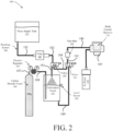
- the plumbing system 180 of device 100 includes various fluid conduits configured to transfer fluid throughout the plumbing system 180 as disclosed further herein.
- the plumbing system 180 comprises a first fluid conduit 181 extending from a water supply tank 110 to a pump 122.
- the pump 122 may comprise an electrically activated pump (i.e., the pump 122 may be configured to convert electrical energy to mechanical energy).
- the pump 122 in response to receiving electrical energy from the power source 104 from FIG. 1 , the pump 122 is configured to pump water from the water supply tank 110 through the first fluid conduit 181 and out an outlet of the pump 122 towards a first valve 208 via a second fluid conduit.
- the first valve 208 comprises an inlet, a first outlet and a second outlet.
- the first valve 208 is in fluid communication with the second outlet in an un-energized state. Although illustrated as being in fluid communication with the second outlet of the first valve 208 in the un-energized state and in fluid communication with the first outlet of the first valve 208 in an energized state, the present disclosure is not limited in this regard.
- the first valve 208 could be in fluid communication with the first outlet of the first valve 208 in the un-energized state.
- the first valve 208 is a solenoid valve.
- a plunger in response to being energized (i.e., an electrical coil receiving current therethrough), a plunger may be actuated to close the second outlet of the first valve 208 and open the first outlet of the first valve 208, in accordance with various embodiments.
- the first outlet of the first valve 208 is in fluid communication with the carbonation vessel 130 via a third fluid conduit 183.
- the second outlet of the first valve 208 is in fluid communication with a first inlet of a second valve 210 via a fourth fluid conduit 184.
- the second valve 210 comprises the first inlet, a second inlet, and an outlet.
- the first inlet of the second valve 210 is in fluid communication with the outlet of the second valve 210 in an un-energized state.
- the present disclosure is not limited in this regard.
- the second inlet of the second valve 210 could be in fluid communication with the outlet of the second valve 210 in the un-energized state, in accordance with various embodiments.
- the second valve 210 is a solenoid valve.
- the outlet of the second valve 210 is in fluid communication with a flow meter 206 via a fifth fluid conduit 185.
- the flow meter 206 is in fluid communication with the nozzle 160 via a sixth fluid conduit 186 of the device 100.
- the controller in response to a controller determining a drink to be mixed is not a carbonated drink, the controller may command the pump 122 to pump water through fluid conduits 181, 182, 184, 185, 186 and out the nozzle 160 combined with a premixed composition of a respective drink capsule as defined further herein.
- the carbon dioxide vessel 140 is in fluid communication with a pressure regulator 204.
- the pressure regulator 204 may be coupled directly to the carbon dioxide vessel 140, may be integral with the carbon dioxide vessel 140, or may be in fluid communication through a seventh fluid conduit 187.
- the present disclosure is not limited in this regard.
- the pressure regulator comprises a valve configured to control a pressure of the carbon dioxide supplied to the carbonation vessel 130. In this regard, based on a command from a controller 102 from FIG. 1 , the pressure of the carbon dioxide supplied to the carbonation vessel 130 may be regulated based on a respective drink capsule as disclosed further herein.
- the pressure regulator 204 is in fluid communication with the carbonation vessel 130 via an eighth fluid conduit 188.
- the carbonation vessel 130 may be configured for continuous carbonation.
- the carbon dioxide vessel 140 may be constantly providing carbon dioxide into the carbonation vessel 130 during operation of the device 100.
- a sensor 202 may be operably coupled to the carbonation vessel 130 configured to measure a level of fluid disposed in the carbonation vessel 130.
- the level sensor may be configured to provide an input as to a height of fluid disposed in the carbonation vessel 130 to provide an indication when the carbon dioxide vessel 140 is low on water, in accordance with various embodiments.
- the carbonation vessel 130 may be a continuous carbonation vessel.
- water from the water supply tank 110 may be supplied to the carbonation vessel 130 (i.e., via energizing first valve 208), and pumping water from the water supply tank 110 via pump 122.
- the carbonation vessel 130 is in fluid communication with the second input of the second valve 210 via a ninth fluid conduit 189.
- the controller 102 from FIG. 1 may energize the first valve 208 and the second valve 210, command the pump 122 to pump water through fluid conduits 181, 182, 183 into the carbonation vessel 130 to form a carbonated water, pump the carbonated water from the carbonation vessel 130 through fluid conduits 189, 185, 186 and out the nozzle 160, and combine the carbonated water with a premixed composition of a respective drink capsule at the nozzle 160 as defined further herein.
- the flow meter 206 may be disposed in the first fluid conduit 181, the second fluid conduit 182, or two flow meters utilized (e.g., one in fourth fluid conduit 184 and one in third fluid conduit 183 or the like), in accordance with various embodiments.
- the device 100 comprises an air pump 124 in fluid communication with the nozzle 160.
- the air pump 124 may be configured to provide a positive pressure to push a remaining fluid out the nozzle 160 proximate an end of a dispensing cycle, in accordance with various embodiments.
- the air pump 124 may be replaced by fluidly coupling the carbon dioxide vessel to a third valve 310 through a second pressure regulator 304 of device 300.
- device 300 is in accordance with device 100, where like numerals denote like elements of device 100.
- the third valve 310 may be in closed in an un-energized state and opened in an energized state.
- a portion of the carbon dioxide may be routed to the nozzle 160 to push a remaining fluid out the nozzle 160, in accordance with various embodiments.
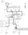
- FIG. 4 a schematic view of a device 400 with a plumbing system 480 configured for on-demand carbonation is illustrated, where like numerals denote like elements of device 100.
- the flow meter 206 from device 100 may be moved from between second valve 210 and nozzle 160 to being between the water supply tank 110 (i.e., fluidly coupled via fluid conduit 481) and the pump 122 (i.e., fluidly coupled via fluid conduit 482), and a pressure transducer 403 may be coupled to the ninth fluid conduit 189 extending from an on-demand carbonation vessel 430 and the second valve 210.
- a single conduit 485 may extend from the second valve 210 to the nozzle 160.
- flow meter 206 and the pressure transducer 403 may provide inputs to the controller 402 from FIG. 1 to regulate a pressure of pump 122 for a drink being carbonated on-demand based on a respective carbonation level for the drink, in accordance with various embodiments.
- a third valve 408 may be disposed between the pressure regulator 204 (i.e., fluidly coupled via fluid conduit 488) and the on-demand carbonation vessel 430 (i.e., fluidly coupled via fluid conduit 489).
- the third valve 408 may be closed in an un-energized state and opened in an energized state.
- a default state of the third valve 408 may correspond to a drink being generated that is non-carbonated, whereas in response to the controller 102 from FIG. 1 determining a drink is to be carbonated, the third valve 408 may be energized to open the third valve 408 and fluidly couple the carbon dioxide vessel 140 to the on-demand carbonation vessel 430.
- the device 400 further comprises a first exhaust fluid conduit 490 extending from the on-demand carbonation vessel 430 to an input of a fourth valve 404 and a second exhaust fluid conduit 491 extending from an output of the fourth valve 404 to an output port.
- the fourth valve 404 is closed in an un-energized state and opened in an energized state. In this regard, in response to a drink dispensing cycle being finished, any remaining carbon dioxide in the on-demand carbonation vessel 430 may be exhausted through the output port of the second exhaust fluid conduit 491.
- the present disclosure is not limited in this regard.
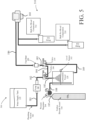
- a schematic view of a device 500 not according to the invention with a plumbing system 580 configured for a plurality of bulk pre-mixed compositions 510 is illustrated, where like numerals denote like elements of device 100.
- the device 500 comprises a plurality of bulk pre-mixed compositions 510, each bulk pre-mixed composition stored in a respective container.
- the bulk pre-mixed compositions 510 include alcohol and a flavoring concentrate, such as a powder composition, a syrup composition, or the like.
- the bulk pre-mixed compositions may include alcohol disposed separately from the flavoring concentrate and configured to be mixed/dispensed together in response to dispensing the bulk pre-mixed composition (e.g., bulk premixed composition 512 or bulk pre-mixed composition 514).
- each pre-mixed composition may be associated with a respective pump in fluid communication with the nozzle 160. In this regard, in response to the controller 502 from FIG.
- the controller may command a respective pump (e.g., pump 522 in response to a user selecting a drink associated with the bulk pre-mixed composition 512), to dispense a predetermined amount of the bulk pre-mixed composition 512 to the nozzle 160 to be mixed with one of a non-carbonated water or a carbonated water as described previously herein.
- a respective pump e.g., pump 522 in response to a user selecting a drink associated with the bulk pre-mixed composition 512
- the present disclosure is not limited in this regard.
- pump 522 being associated with bulk pre-mixed composition 512 and pump 524 being associated with pump 524
- a single pump may be utilized and a valve may be configured to open or close as described previously herein to fluidly couple a selected bulk pre-mixed composition to the nozzle 160, in accordance with various embodiments.
- the present disclosure is not limited in this regard.
- the device 500 may include a carbonation system in accordance with device 300 or device 400, in accordance with various embodiments.
- the carbonation system of device 500 may be configured to utilize the carbon dioxide in the carbon dioxide vessel 140 to push a remaining fluid out the nozzle 160 in accordance with device 300, or may include an on-demand carbonation vessel 430 in accordance with device 400, in accordance with various embodiments.
- the present disclosure is not limited in this regard.
- control system 200 comprises the controller 102 of device 100 from FIG. 1 .
- controller 102 may be configured as a central network element or hub to access various systems and components of control system 200.
- controller 102 may comprise a processor.
- controller 102 may be implemented in a single processor.
- controller 102 may be implemented as and may include one or more processors and/or one or more tangible, non-transitory memories (e.g., memory) and be capable of implementing logic.
- Each processor can be a general purpose processor, a digital signal processor (“DSP”), an application specific integrated circuit (“ASIC”), a field programmable gate array (“FPGA”) or other programmable logic device, discrete gate or transistor logic, discrete hardware components, or any combination thereof.
- Controller 102 may comprise a processor configured to implement various logical operations in response to execution of instructions, for example, instructions stored on a non-transitory, tangible, computer-readable medium configured to communicate with controller 102.
- System program instructions and/or controller instructions may be loaded onto a non-transitory, tangible computer-readable medium having instructions stored thereon that, in response to execution by a controller, cause the controller to perform various operations.
- the term "non-transitory” is to be understood to remove only propagating transitory signals per se from the claim scope and does not relinquish rights to all standard computer-readable media that are not only propagating transitory signals per se. Stated another way, the meaning of the term “non-transitory computer-readable medium” and “non-transitory computer-readable storage medium” should be construed to exclude only those types of transitory computer-readable media which were found in In Re Nuijten to fall outside the scope of patentable subject matter under 35 U.S.C. ⁇ 101.
- the controller 102 is in electronic communication (e.g., wirelessly or electrically) with the sensor 202, a capsule sensor 212, the flow meter 206, the pressure regulator 204 and the power source 104 of device 100.
- the controller 102 is configured to receive data from the sensor 202, the pressure regulator 204, the flow meter 206, and the capsule sensor 212.
- the controller 102 may command power source 104 to provide electrical power to various components in response to data received during operation of the device 100 as described further herein.
- the capsule sensor 212 may be disposed in the drink capsule receiver 121.
- the capsule sensor 212 is configured to provide drink data to the controller 102 for the controller to act on.
- the capsule sensor 212 may comprise a radio frequency identification (“RFID”) reader, a camera, a scanner, or the like.
- RFID radio frequency identification
- a drink capsule may comprise a drink identifier that the capsule sensor 212 is configured to read, such as an RFID tag, a barcode, or the like.
- control system 700 for the device 300 from FIGs. 1 and 3 is illustrated, where like numerals denote like elements of control system 200 from FIG. 6 , in accordance with various embodiments.
- the control system 700 comprises a controller 302.
- the controller 302 is in accordance with the controller 102 except as otherwise described herein.
- the control system 700 is in accordance with control system 200 with the exception that air pump 124 is removed, the pressure regulator 304 is added and the third valve 310 is added.
- the pressure regulator 304 is in electronic (i.e., electrical or wireless) communication with the controller 302.
- the pressure regulator 304 is configured to provide data to the controller as to a pressure being measured between the carbon dioxide vessel 140 and the nozzle 160 of device 300 from FIG. 3 , in accordance with various embodiments.
- the controller 302 may be configured to monitor and regulate the pressure in response to the data, in accordance with various embodiments.
- the third valve 310 is in electrical communication with the controller 302.
- a remaining fluid may be pushed out of the nozzle 160 of device 300 from FIG. 3 in response to the controller 302 commanding the power source to energize the third valve 310, in accordance with various embodiments.
- control system 800 for the device 400 from FIGs. 1 and 4 is illustrated, where like numerals denote like elements of control system 200 from FIG. 6 , in accordance with various embodiments.
- the control system 800 comprises a controller 402.
- the controller 402 is in accordance with the controller 102 except as otherwise described herein.
- the control system 800 is in accordance with control system 200 with the exception that control system 800 further comprises the third valve 408 and the fourth valve 404.
- the third valve 408 and the fourth valve 404 are in electrical communication with the power source 104.
- the controller 402 is configured to open the third valve 408 by energizing the third valve 408 in response to determining a respective beverage to be mixed is to be carbonated.
- the controller 402 may control the pressure regulator 204 to control an amount of carbon dioxide to supply to the on-demand carbonation vessel 430 of device 400 from FIG. 4 and de-energize the third valve 408 upon completing a dispensing cycle, in accordance with various embodiments.
- the controller 402 is configured to command (e.g., through the power source 104) energizing fourth valve 404 to exhaust carbon dioxide from the on-demand carbonation vessel 430 of device 400 from FIG. 4 in response to completing the dispensing cycle, in accordance with various embodiments.
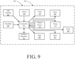
- control system 900 for the device 500 from FIGs. 1 and 5 is illustrated, where like numerals denote like elements of control system 200 from FIG. 6 , in accordance with various embodiments.
- the control system 900 comprises a controller 502.
- the controller 502 is in accordance with the controller 102 except as otherwise described herein.
- the control system 900 is in accordance with control system 200 with the exception that control system 900 does not include the capsule sensor 212 and further comprises pumps 522, 524 and a user interface 902.
- the user interface 902 includes a graphical user interface which may be accessible by a display device via an application, web browser, software application, or the like.
- a capsule sensor 212 is not used.
- a user may select a drink from a list of mixed drinks for the device 500 from FIG. 5 .
- the controller may determine a bulk pre-mixed composition from a plurality of bulk pre-mixed compositions 510 from FIG. 5 from which to dispense through nozzle 160 of device 500, in accordance with various embodiments.
- the controller 502 may activate a pump (e.g., pump 522 or pump 524) associated with a respective bulk pre-mixed composition (e.g., bulk pre-mixed composition 512 or bulk pre-mixed composition 514), in accordance with various embodiments.
- a pump e.g., pump 522 or pump 524 associated with a respective bulk pre-mixed composition (e.g., bulk pre-mixed composition 512 or bulk pre-mixed composition 514), in accordance with various embodiments.
- the process 10 comprises determining via a controller, a mixed drink to be dispensed (step 12).
- determining the mixed drink may be based on receiving an identifier from a capsule sensor (e.g., capsule sensor 212 of control systems 200, 700, 800) as disclosed previously herein.
- determining the mixed drink may be based on receiving a selected drink from a user interface (e.g., user interface 902 from control system 900).
- the process 10 further comprises determining whether the mixed drink to be dispensed includes carbonation (step 14).
- each identifier for a mixed drink in accordance with control systems 200, 700, 800 and each selectable drink from a user interface in accordance with control system 900 may include the following data: carbonation data (i.e., carbonated or not), volume data (i.e., a volume of water or carbonated water to be dispensed), or the like.
- the process 10 further comprises commanding, via the controller, dispensing of a pre-determined volume of carbonated water in response to determining the mixed drink is a carbonated mixed drink (step 16).
- control systems 200, 700 may dispense carbonated water in accordance with step 16 from the carbonation vessel 130 which is continuously carbonated as described previously herein.
- the second valve 210 may be energized by the controller 102, 302 of the control system 200, 700, pressure from the carbonation vessel 130 may propel the carbonated water out the nozzle 160 of the device 100, 300, and the flow meter 206 may provide data to the controller 102, 302 to ensure the volume of carbonated water is in accordance with the mixed drink of step 12.
- control system 800 may energize, via a command from the controller 402, the first valve 208 and the fourth valve 404 (i.e., to provide a vent during filling of the on-demand carbonation vessel).
- the control system 800 may proceed to fill the on-demand carbonation vessel 430 with a predetermined volume of water associated with a drink being dispensed.
- the control system 800 may fill the on-demand carbonation vessel 430 based on data received from the flow meter 206.
- the controller 402 may de-energize the pump 122, the valve 208, and the third valve 404.
- the controller 402 may further energize valve 408 to pressurize the on-demand carbonation vessel 430 to a predetermined pressure.
- pressure transducer 403 may provide pressure data to the controller 402 to ensure the pressure of the on-demand carbonation vessel 430 meets the predetermined pressure.
- the controller 402 in response to the predetermined pressure being met or exceeded, the controller 402 may de-energize valve 408 and energize valve 210 to dispense the carbonated water.
- carbonated water may be formed in the on-demand carbonation vessel 430 by regulating, via the pump 122 (in response to controller receiving data from flow meter 206) and pressure regulator 204 and an amount of water supplied from water supply tank 110 and an amount of carbon dioxide supplied from carbon dioxide vessel 140, in accordance with various embodiments.
- the pressure transducer 403 may provide pressure data to the controller 402.
- control system 900 may dispense the carbonated water in accordance with control system 200, control system 700, or control system 800 as outlined above.
- the process 10 further comprises commanding, via the controller, dispensing of a pre-mixed composition associated with the mixed drink (step 18).
- the pre-mixed composition may be dispensed via the dispensing head 150 from FIG. 1 by breaking a seal of a drink capsule (e.g., for control systems 200, 700, 800) or by activating a pump (e.g., pump 522 or pump 524 of device 500) associated with the pre-mixed composition (e.g., bulk pre-mixed composition 512 or bulk pre-mixed composition 514 of device 500), in accordance with various embodiments.
- steps 16 and 18 may be performed simultaneously.
- the bulk pre-mixed composition associated with the mixed drink may be configured to release a pre-determined volume of the pre-mixed composition prior to pumping the pre-mixed composition through the nozzle 160, in accordance with various embodiments.
- the process 10 further comprises commanding, via the controller, dispensing of a pre-determined volume of non-carbonated water in response to determining the mixed drink is a non-carbonated mixed drink (step 20).
- the controller 102, 302, 402, 502 may command the pump 122 to pump a pre-determined volume of water through the nozzle 160.
- the controller 102, 302, 402, 502 may monitor the amount of non-carbonated water being dispensed via flow meter 206.
- the process 10 further comprises commanding, via the controller, dispensing of the pre-mixed composition associated with the mixed drink (step 22).
- step 22 may be similar to step 18 as described above.
- the pre-mixed composition may be dispensed via the dispensing head 150 from FIG. 1 by breaking a seal of a drink capsule (e.g., for control systems 200, 700, 800) or by activating a pump (e.g., pump 522 or pump 524 of device 500) associated with the pre-mixed composition (e.g., bulk pre-mixed composition 512 or bulk pre-mixed composition 514 of device 500), in accordance with various embodiments.
- steps 20 and 22 may be performed simultaneously.
- the bulk pre-mixed composition associated with the mixed drink may be configured to release a pre-determined volume of the pre-mixed composition prior to pumping the pre-mixed composition through the nozzle 160, in accordance with various embodiments.
Landscapes
- Devices For Dispensing Beverages (AREA)
Claims (15)
- Getränkemischvorrichtung, umfassend:ein Gehäuse (101);einen von dem Gehäuse beabstandeten Abgabekopf (150);eine mit dem Abgabekopf verbundene Düse (160);eine Kapselaufnahme (121), die zum Aufnehmen einer Kapsel konfiguriert ist, die eine vorgemischte Zusammensetzung beinhaltet, wobei die Kapselaufnahme einen ersten Sensor (202) beinhaltet;einen innerhalb des Gehäuses angeordneten Wasservorratstank (110) ;ein innerhalb des Gehäuses angeordnetes Karbonisierungsgefäß (130), wobei das Karbonisierungsgefäß für die Karbonisierung auf Verlangen konfiguriert ist; undeine Steuerung in elektronischer Kommunikation mit dem ersten Sensor, wobei die Steuerung zu Folgendem konfiguriert ist:Bestimmen einer Getränkeart basierend auf dem Empfangen von Sensordaten von dem ersten Sensor, unddadurch gekennzeichnet, dass die Steuerung ferner zu Folgendem konfiguriert ist:
Abgeben eines kohlensäurehaltigen Wassers oder eines nicht kohlensäurehaltigen Wassers basierend auf der Getränkeart. - Getränkemischvorrichtung nach Anspruch 1, wobei die Getränkemischvorrichtung eines von mobil oder stationär ist.
- Getränkemischvorrichtung nach Anspruch 1, ferner umfassend eine Pumpe (122), die zwischen dem Wasservorratstank (110) und einem ersten Ventil (208) angeordnet ist, wobei die Steuerung ferner zum Aktivieren des ersten Ventils (208) konfiguriert ist, um den Wasservorratstank (110) als Reaktion darauf, dass die Steuerung eine Angabe empfängt, dass die Getränkeart kohlensäurehaltiges Wasser verwendet, fluidisch an das Gefäß für die Karbonisierung auf Verlangen (130) zu koppeln.
- Getränkemischvorrichtung nach Anspruch 3, wobei:das erste Ventil (208) einen ersten Einlass, einen ersten Auslass und einen zweiten Auslass aufweist,sich eine erste Fluidleitung von dem zweiten Auslass zu einem ersten Einlass eines zweiten Ventils (210) erstreckt,wobei das zweite Ventil (210) den ersten Einlass, einen zweiten Einlass in Fluidkommunikation mit dem Karbonisierungsgefäß und einen ersten Auslass in Fluidkommunikation mit der Düse beinhaltet.
- Getränkemischvorrichtung nach Anspruch 4, ferner umfassend einen Durchflussmesser (206), der zwischen dem Wasservorratstank (110) und der Pumpe (122) angeordnet ist, wobei der Durchflussmesser (206) in elektronischer Kommunikation mit der Steuerung steht und wobei die Steuerung vorzugsweise ferner zum Befehlen des Pumpens von Wasser über die Pumpe aus dem Wasservorratstank als Reaktion auf das Bestimmen, dass die Getränkeart zum Mischen ein nicht kohlensäurehaltiges Wasser beinhaltet, konfiguriert ist.
- Getränkemischvorrichtung nach Anspruch 4, ferner umfassend ein drittes Ventil (310), das zwischen einem Kohlendioxidgefäß und dem Gefäß für Karbonisierung auf Verlangen angeordnet ist.
- Getränkemischvorrichtung nach Anspruch 6, wobei die Steuerung als Reaktion auf das Bestimmen, dass die Getränkeart ein kohlensäurehaltiges Wasser beinhaltet, ferner zu Folgendem konfiguriert ist:Aktivieren des ersten Ventils (208), um den Wasservorratstank fluidisch an das Gefäß für Karbonisierung auf Verlangen zu koppeln,Aktivieren des dritten Ventils (310), um das Kohlendioxidgefäß fluidisch an das Gefäß für Karbonisierung auf Verlangen zu koppeln, undAktivieren des zweiten Ventils (210), um das Gefäß für Karbonisierung auf Verlangen fluidisch an die Düse zu koppeln.
- Herstellungsgegenstand, der ein physisches, nichtflüchtiges computerlesbares Speichermedium beinhaltet, das darauf gespeicherte Anweisungen aufweist, die als Reaktion auf die Ausführung durch einen Prozessor den Prozessor zum Durchführen von Vorgängen veranlassen, umfassend:Empfangen einer Kennung von einem in einer Getränkemischvorrichtung angeordneten Sensor über einen Prozessor, wobei der Sensor zum Erfassen der Kennung auf einer Kapsel konfiguriert ist, die eine vorgemischte Zusammensetzung beinhaltet;Bestimmen einer der Kennung zugeordneten Getränkeart über den Prozessor;Bestimmen über den Prozessor, dass die Getränkeart ein kohlensäurehaltiges Wasser beinhaltet;Aktivieren eines ersten Ventils über den Prozessor zum fluidischen Koppeln eines Wasservorratstanks an ein Gefäß für Karbonisierung auf Verlangen;Aktivieren eines zweiten Ventils über den Prozessor zum Entlüften des Gefäßes für Karbonisierung auf Verlangen während des Befüllens des Gefäßes für Karbonisierung auf Verlangen mit Wasser;Deaktivieren des ersten Ventils und des zweiten Ventils über den Prozessor;Aktivieren eines dritten Ventils über den Prozessor zum fluidischen Koppeln eines Kohlendioxidgefäßes an das Gefäß für Karbonisierung auf Verlangen; undAktivieren eines vierten Ventils über den Prozessor zum fluidischen Koppeln des Gefäßes für Karbonisierung auf Verlangen an eine Düse, wobei die Düse zum Abgeben des kohlensäurehaltigen Wassers und der vorgemischten Zusammensetzung konfiguriert ist.
- Herstellungsgegenstand nach Anspruch 8, wobei die Vorgänge ferner: Empfangen von Druckdaten über den Prozessor von einem Druckwandler, der zwischen dem Gefäß für Karbonisierung auf Verlangen und dem dritten Ventil angeordnet ist, umfassen.
- Herstellungsgegenstand nach Anspruch 9, wobei die Vorgänge ferner Deaktivieren des dritten Ventils als Reaktion darauf umfassen, dass ein Druck in den Druckdaten einen Druckschwellenwert überschreitet, und wobei das Deaktivieren des ersten Ventils und des vierten Ventils vorzugsweise als Reaktion auf das Bestimmen basierend auf von einem Durchflussmesser empfangenen Daten erfolgt, dass sich in dem Gefäß für Karbonisierung auf Verlangen ein vorbestimmtes Wasservolumen befindet.
- Herstellungsgegenstand nach Anspruch 9, wobei die Vorgänge ferner Befehlen einer Luftpumpe über den Prozessor umfassen, Luft durch die Düse zu pumpen.
- Herstellungsgegenstand nach Anspruch 8, wobei die Vorgänge ferner als Reaktion auf das Bestimmen, dass die Getränkeart ein nicht kohlensäurehaltiges Wasser als Mixer beinhaltet, Befehlen einer Pumpe über den Prozessor umfassen, nicht kohlensäurehaltiges Wasser aus dem Wasservorratstank zu pumpen.
- Steuersystem für eine Getränkemischvorrichtung, wobei das Steuersystem Folgendes umfasst:einen Sensor;eine Fluidpumpe (122), die dazu konfiguriert ist, in Fluidkommunikation mit einem Wasservorratstank (110) zu stehen;ein erstes Ventil (208) in Fluidkommunikation mit der Fluidpumpe;ein zweites Ventil (210), das dazu konfiguriert ist, zwischen der Fluidpumpe und einer Düse angeordnet zu sein ein drittes Ventil (310), das dazu konfiguriert ist, zwischen einem Kohlendioxidgefäß und einem Gefäß für Karbonisierung auf Verlangen angeordnet zu sein;ein viertes Ventil (404), das dazu konfiguriert ist, zwischen dem Kohlendioxidgefäß und einer Entlüftungsöffnung angeordnet zu sein; undeine Steuerung in elektronischer Kommunikation mit der Fluidpumpe, dem ersten Ventil, dem zweiten Ventil, dem dritten Ventil, dem vierten Ventil und dem Sensor, wobei die Steuerung zu Folgendem konfiguriert ist:Empfangen einer Kennung von dem Sensor, wobei der Sensor zum Erfassen einer Kennung auf einer Kapsel konfiguriert ist, wobei die Kapsel eine vorgemischte Zusammensetzung beinhaltet, wobei die Kennung einer Getränkeart entspricht;Bestimmen, ob die Getränkeart ein kohlensäurehaltiges Wasser oder ein nicht kohlensäurehaltiges Wasser beinhaltet;Aktivieren des ersten und des vierten Ventils zum Abgeben von Wasser in das Gefäß für Karbonisierung auf Verlangen;Aktivieren des dritten Ventils zum Abgeben von Kohlendioxid in das Gefäß für Karbonisierung auf Verlangen; undAktivieren des zweiten Ventils zum Abgeben des durch Aktivieren des ersten und des dritten Ventils gebildeten kohlensäurehaltigen Wassers.
- Steuersystem nach Anspruch 13, ferner umfassend ein Karbonisierungsgefäß und einen Druckwandler (403), der zum Messen eines Drucks in dem Karbonisierungsgefäß konfiguriert ist, und wobei die Steuerung vorzugsweise ferner zum Empfangen von Druckdaten von dem Druckwandler konfiguriert ist und wobei das Steuersystem noch bevorzugter zum Aktivieren des vierten Ventils beim Befüllen des Karbonisierungsgefäßes mit Wasser aus dem Wasservorratstank konfiguriert ist.
- Steuersystem nach Anspruch 13, ferner umfassend eine Luftpumpe (124), die zum fluidischen Koppeln an eine Düse (160) konfiguriert ist, wobei das zweite Ventil (210) fluidisch an die Düse (160) gekoppelt ist und wobei die Steuerung vorzugsweise ferner zum Befehlen der Luftpumpe konfiguriert ist, Druckluft durch die Düse abzugeben.
Applications Claiming Priority (1)
| Application Number | Priority Date | Filing Date | Title |
|---|---|---|---|
| US17/458,036 US12122655B2 (en) | 2021-08-26 | 2021-08-26 | Beverage devices, systems, and methods |
Publications (2)
| Publication Number | Publication Date |
|---|---|
| EP4140940A1 EP4140940A1 (de) | 2023-03-01 |
| EP4140940B1 true EP4140940B1 (de) | 2024-12-18 |
Family
ID=83005889
Family Applications (1)
| Application Number | Title | Priority Date | Filing Date |
|---|---|---|---|
| EP22191515.0A Active EP4140940B1 (de) | 2021-08-26 | 2022-08-22 | Getränkevorrichtungen, -systeme und -verfahren |
Country Status (3)
| Country | Link |
|---|---|
| US (3) | US12122655B2 (de) |
| EP (1) | EP4140940B1 (de) |
| CN (1) | CN115725377B (de) |
Families Citing this family (1)
| Publication number | Priority date | Publication date | Assignee | Title |
|---|---|---|---|---|
| WO2023034463A1 (en) * | 2021-08-31 | 2023-03-09 | Versabev, Inc. | Systems and methods for refilling, storing, preserving, managing, and selectively dispensing beverages |
Family Cites Families (33)
| Publication number | Priority date | Publication date | Assignee | Title |
|---|---|---|---|---|
| US659657A (en) * | 1899-10-26 | 1900-10-16 | Arthur M Gerow | Carbonating apparatus. |
| US2612304A (en) * | 1946-03-13 | 1952-09-30 | Alexander I Martin | Drink dispensing apparatus for carbonated beverages |
| US2655858A (en) * | 1948-06-16 | 1953-10-20 | Halley H Hamlin | Beverage dispensing apparatus |
| NL7308179A (de) * | 1972-06-20 | 1973-12-27 | ||
| US3949902A (en) | 1973-06-11 | 1976-04-13 | Thompson Frank B | Portable dispensing bar |
| GB8611389D0 (en) | 1986-05-09 | 1986-06-18 | Cadbury Schweppes Plc | Carbonating apparatus |
| US5411179A (en) | 1993-08-31 | 1995-05-02 | S.O.B. Partnership | Self-contained beverage dispensing system |
| US5765726A (en) | 1995-09-27 | 1998-06-16 | Imi Wilshire Inc. | Combined carbonated and non-carbonated beverage dispenser |
| US6820763B2 (en) | 2002-03-13 | 2004-11-23 | Sb Partnership, Inc. | Portable beverage dispensing systems |
| US10859072B2 (en) | 2007-09-06 | 2020-12-08 | Deka Products Limited Partnership | Product dispensing system |
| CN102245496B (zh) * | 2009-07-23 | 2015-05-13 | 斯马特巴尔国际有限责任公司 | 自动饮料配制器 |
| US8768524B2 (en) | 2010-06-04 | 2014-07-01 | Pepsico, Inc. | System and method for rapid reconfiguration of post-mix beverage dispenser |
| AU2013217541B2 (en) | 2012-02-09 | 2017-05-25 | Keurig Green Mountain, Inc. | Beverage forming device and method with cartridge retainer |
| US10524609B2 (en) | 2013-03-14 | 2020-01-07 | Altria Client Services Llc | Disposable beverage pod and apparatus for making a beverage |
| WO2015148710A1 (en) | 2014-03-26 | 2015-10-01 | Secor Water, Llc | Water station with integrated qr code-reading system for user access |
| EP4116257A1 (de) | 2014-04-30 | 2023-01-11 | The Coca-Cola Company | Verfahren und vorrichtung zur pulsierten abgabe einer mischung aus stillem wasser und kohlensäurehaltigem wasser |
| CA2947610A1 (en) | 2014-05-12 | 2015-11-19 | The Coca-Cola Company | Beverage dispenser system with remote ingredients handling |
| JP6385797B2 (ja) * | 2014-10-31 | 2018-09-05 | パナソニック株式会社 | 飲料供給装置 |
| AU2016210828B2 (en) | 2015-01-30 | 2020-09-03 | Anheuser-Busch Inbev S.A. | Pressurized beverage concentrates and appliances and methods for producing beverages therefrom |
| US10336597B2 (en) | 2015-03-23 | 2019-07-02 | Altria Client Services Llc | Capsule-based alcoholic beverage forming apparatus and components thereof |
| WO2016178734A1 (en) | 2015-05-07 | 2016-11-10 | Juicero, Inc. | Juicing system with supplemental liquid to form a juice beverage |
| EP3355715A4 (de) * | 2015-09-30 | 2019-07-03 | Hydration Labs Inc. | Getränkeausgabe |
| EP3275834A1 (de) | 2016-07-26 | 2018-01-31 | Anheuser-Busch InBev S.A. | Abgabevorrichtung zur infusion einer kohlensäurehaltigen getränkeflüssigkeit mit zutaten und verfahren dafür |
| US10252900B2 (en) | 2016-12-07 | 2019-04-09 | Cornelius Beverage Technologies Limited | Apparatuses, systems, and methods for dispensing beverages using alcoholic concentrates |
| CN110392664B (zh) | 2017-01-27 | 2022-01-14 | 可口可乐公司 | 用于将微量配料分配功能合并到大量配料饮料分配系统中的系统和方法 |
| CN112218819A (zh) | 2018-03-22 | 2021-01-12 | 贝德福德系统有限责任公司 | 用于使容器中的液体碳酸化并检测二氧化碳源中的二氧化碳水平的系统和方法 |
| EP3784620A4 (de) | 2018-04-26 | 2022-01-12 | PepsiCo, Inc. | Systeme und verfahren zur ausgabe eines getränks |
| GB2576379B (en) * | 2018-08-17 | 2021-05-12 | Lavazza Professional Uk Ltd | Beverage dispensing apparatus and method |
| WO2020097558A1 (en) | 2018-11-08 | 2020-05-14 | Bedford Systems Llc | Multi-use beverage system |
| DE102019204156A1 (de) | 2019-03-26 | 2020-10-01 | BSH Hausgeräte GmbH | Getränkesystem zur Herstellung eines Getränks mittels einer Kapsel |
| US12304797B2 (en) | 2019-11-22 | 2025-05-20 | Pepsico, Inc. | Mobile product dispenser |
| US11565930B2 (en) | 2020-06-04 | 2023-01-31 | Appliance Development Corporation | Smart phone drink maker |
| US11802038B2 (en) | 2021-03-05 | 2023-10-31 | Lancer Corporation | Method and apparatus for configuring and maintaining a beverage dispenser |
-
2021
- 2021-08-26 US US17/458,036 patent/US12122655B2/en active Active
-
2022
- 2022-08-22 EP EP22191515.0A patent/EP4140940B1/de active Active
- 2022-08-26 CN CN202211031779.4A patent/CN115725377B/zh active Active
-
2024
- 2024-08-27 US US18/816,253 patent/US20240417234A1/en active Pending
- 2024-09-25 US US18/896,642 patent/US20250011152A1/en active Pending
Also Published As
| Publication number | Publication date |
|---|---|
| US20230069257A1 (en) | 2023-03-02 |
| CN115725377B (zh) | 2025-01-28 |
| US20250011152A1 (en) | 2025-01-09 |
| US12122655B2 (en) | 2024-10-22 |
| US20240417234A1 (en) | 2024-12-19 |
| EP4140940A1 (de) | 2023-03-01 |
| CN115725377A (zh) | 2023-03-03 |
Similar Documents
| Publication | Publication Date | Title |
|---|---|---|
| US12312228B2 (en) | Beverage devices, systems, and methods | |
| EP4140938A2 (de) | Getränkevorrichtungen, systeme und verfahren | |
| US11905155B2 (en) | Scalable modular system and method for storing, preserving, managing, and selectively dispensing beverages | |
| US12122659B2 (en) | Scalable modular system and method for valve control and selectively dispensing beverages | |
| US10336597B2 (en) | Capsule-based alcoholic beverage forming apparatus and components thereof | |
| EP3142960B1 (de) | Getränkespendersystem mit remote-handhabung von inhaltsstoffen | |
| US20090214742A1 (en) | Device and method for preparing aromatic hot drinks, particularly coffee and tea | |
| RU2013103533A (ru) | Система и способ приготовления и раздачи напитка | |
| US11655134B1 (en) | Modular beverage dispenser and methods of use | |
| US20180265344A1 (en) | Wireless Control System for Dispensing Beverages from a Bottle | |
| CN106030670A (zh) | 饮料分装容器、装置、系统及方法 | |
| US20250011152A1 (en) | Beverage devices, systems, and methods | |
| WO2020047612A1 (en) | A beverage mixer/dispenser for bespoke beverages | |
| US20150344284A1 (en) | Automatic fluid dispenser | |
| US20240400365A1 (en) | Scalable systems and methods for selectively dispensing beverages | |
| EP3110710B1 (de) | System zur speicherung und selektiven ausgabe zumindest eines flüssigkeitsvolumens | |
| US8613244B2 (en) | Method for the production of tea beverages and other beverages | |
| EP1344743B1 (de) | Bierausgabevorrichtung | |
| US20260084951A1 (en) | Beverage dispenser for mixed drinking dispensing |
Legal Events
| Date | Code | Title | Description |
|---|---|---|---|
| PUAI | Public reference made under article 153(3) epc to a published international application that has entered the european phase |
Free format text: ORIGINAL CODE: 0009012 |
|
| STAA | Information on the status of an ep patent application or granted ep patent |
Free format text: STATUS: THE APPLICATION HAS BEEN PUBLISHED |
|
| AK | Designated contracting states |
Kind code of ref document: A1 Designated state(s): AL AT BE BG CH CY CZ DE DK EE ES FI FR GB GR HR HU IE IS IT LI LT LU LV MC MK MT NL NO PL PT RO RS SE SI SK SM TR |
|
| STAA | Information on the status of an ep patent application or granted ep patent |
Free format text: STATUS: REQUEST FOR EXAMINATION WAS MADE |
|
| 17P | Request for examination filed |
Effective date: 20230626 |
|
| RBV | Designated contracting states (corrected) |
Designated state(s): AL AT BE BG CH CY CZ DE DK EE ES FI FR GB GR HR HU IE IS IT LI LT LU LV MC MK MT NL NO PL PT RO RS SE SI SK SM TR |
|
| P01 | Opt-out of the competence of the unified patent court (upc) registered |
Effective date: 20230928 |
|
| GRAP | Despatch of communication of intention to grant a patent |
Free format text: ORIGINAL CODE: EPIDOSNIGR1 |
|
| STAA | Information on the status of an ep patent application or granted ep patent |
Free format text: STATUS: GRANT OF PATENT IS INTENDED |
|
| INTG | Intention to grant announced |
Effective date: 20240801 |
|
| GRAS | Grant fee paid |
Free format text: ORIGINAL CODE: EPIDOSNIGR3 |
|
| GRAA | (expected) grant |
Free format text: ORIGINAL CODE: 0009210 |
|
| STAA | Information on the status of an ep patent application or granted ep patent |
Free format text: STATUS: THE PATENT HAS BEEN GRANTED |
|
| AK | Designated contracting states |
Kind code of ref document: B1 Designated state(s): AL AT BE BG CH CY CZ DE DK EE ES FI FR GB GR HR HU IE IS IT LI LT LU LV MC MK MT NL NO PL PT RO RS SE SI SK SM TR |
|
| REG | Reference to a national code |
Ref country code: CH Ref legal event code: EP |
|
| REG | Reference to a national code |
Ref country code: DE Ref legal event code: R096 Ref document number: 602022008790 Country of ref document: DE |
|
| REG | Reference to a national code |
Ref country code: IE Ref legal event code: FG4D |
|
| REG | Reference to a national code |
Ref country code: LT Ref legal event code: MG9D |
|
| PG25 | Lapsed in a contracting state [announced via postgrant information from national office to epo] |
Ref country code: HR Free format text: LAPSE BECAUSE OF FAILURE TO SUBMIT A TRANSLATION OF THE DESCRIPTION OR TO PAY THE FEE WITHIN THE PRESCRIBED TIME-LIMIT Effective date: 20241218 |
|
| PG25 | Lapsed in a contracting state [announced via postgrant information from national office to epo] |
Ref country code: FI Free format text: LAPSE BECAUSE OF FAILURE TO SUBMIT A TRANSLATION OF THE DESCRIPTION OR TO PAY THE FEE WITHIN THE PRESCRIBED TIME-LIMIT Effective date: 20241218 |
|
| PG25 | Lapsed in a contracting state [announced via postgrant information from national office to epo] |
Ref country code: BG Free format text: LAPSE BECAUSE OF FAILURE TO SUBMIT A TRANSLATION OF THE DESCRIPTION OR TO PAY THE FEE WITHIN THE PRESCRIBED TIME-LIMIT Effective date: 20241218 |
|
| PG25 | Lapsed in a contracting state [announced via postgrant information from national office to epo] |
Ref country code: NO Free format text: LAPSE BECAUSE OF FAILURE TO SUBMIT A TRANSLATION OF THE DESCRIPTION OR TO PAY THE FEE WITHIN THE PRESCRIBED TIME-LIMIT Effective date: 20250318 |
|
| REG | Reference to a national code |
Ref country code: NL Ref legal event code: MP Effective date: 20241218 |
|
| PG25 | Lapsed in a contracting state [announced via postgrant information from national office to epo] |
Ref country code: GR Free format text: LAPSE BECAUSE OF FAILURE TO SUBMIT A TRANSLATION OF THE DESCRIPTION OR TO PAY THE FEE WITHIN THE PRESCRIBED TIME-LIMIT Effective date: 20250319 Ref country code: LV Free format text: LAPSE BECAUSE OF FAILURE TO SUBMIT A TRANSLATION OF THE DESCRIPTION OR TO PAY THE FEE WITHIN THE PRESCRIBED TIME-LIMIT Effective date: 20241218 |
|
| PG25 | Lapsed in a contracting state [announced via postgrant information from national office to epo] |
Ref country code: RS Free format text: LAPSE BECAUSE OF FAILURE TO SUBMIT A TRANSLATION OF THE DESCRIPTION OR TO PAY THE FEE WITHIN THE PRESCRIBED TIME-LIMIT Effective date: 20250318 |
|
| PG25 | Lapsed in a contracting state [announced via postgrant information from national office to epo] |
Ref country code: NL Free format text: LAPSE BECAUSE OF FAILURE TO SUBMIT A TRANSLATION OF THE DESCRIPTION OR TO PAY THE FEE WITHIN THE PRESCRIBED TIME-LIMIT Effective date: 20241218 |
|
| REG | Reference to a national code |
Ref country code: AT Ref legal event code: MK05 Ref document number: 1752134 Country of ref document: AT Kind code of ref document: T Effective date: 20241218 |
|
| PG25 | Lapsed in a contracting state [announced via postgrant information from national office to epo] |
Ref country code: SM Free format text: LAPSE BECAUSE OF FAILURE TO SUBMIT A TRANSLATION OF THE DESCRIPTION OR TO PAY THE FEE WITHIN THE PRESCRIBED TIME-LIMIT Effective date: 20241218 |
|
| PG25 | Lapsed in a contracting state [announced via postgrant information from national office to epo] |
Ref country code: PL Free format text: LAPSE BECAUSE OF FAILURE TO SUBMIT A TRANSLATION OF THE DESCRIPTION OR TO PAY THE FEE WITHIN THE PRESCRIBED TIME-LIMIT Effective date: 20241218 |
|
| PG25 | Lapsed in a contracting state [announced via postgrant information from national office to epo] |
Ref country code: ES Free format text: LAPSE BECAUSE OF FAILURE TO SUBMIT A TRANSLATION OF THE DESCRIPTION OR TO PAY THE FEE WITHIN THE PRESCRIBED TIME-LIMIT Effective date: 20241218 |
|
| PG25 | Lapsed in a contracting state [announced via postgrant information from national office to epo] |
Ref country code: IS Free format text: LAPSE BECAUSE OF FAILURE TO SUBMIT A TRANSLATION OF THE DESCRIPTION OR TO PAY THE FEE WITHIN THE PRESCRIBED TIME-LIMIT Effective date: 20250418 |
|
| PG25 | Lapsed in a contracting state [announced via postgrant information from national office to epo] |
Ref country code: PT Free format text: LAPSE BECAUSE OF FAILURE TO SUBMIT A TRANSLATION OF THE DESCRIPTION OR TO PAY THE FEE WITHIN THE PRESCRIBED TIME-LIMIT Effective date: 20250421 |
|
| PG25 | Lapsed in a contracting state [announced via postgrant information from national office to epo] |
Ref country code: EE Free format text: LAPSE BECAUSE OF FAILURE TO SUBMIT A TRANSLATION OF THE DESCRIPTION OR TO PAY THE FEE WITHIN THE PRESCRIBED TIME-LIMIT Effective date: 20241218 |
|
| PG25 | Lapsed in a contracting state [announced via postgrant information from national office to epo] |
Ref country code: RO Free format text: LAPSE BECAUSE OF FAILURE TO SUBMIT A TRANSLATION OF THE DESCRIPTION OR TO PAY THE FEE WITHIN THE PRESCRIBED TIME-LIMIT Effective date: 20241218 Ref country code: AT Free format text: LAPSE BECAUSE OF FAILURE TO SUBMIT A TRANSLATION OF THE DESCRIPTION OR TO PAY THE FEE WITHIN THE PRESCRIBED TIME-LIMIT Effective date: 20241218 |
|
| PG25 | Lapsed in a contracting state [announced via postgrant information from national office to epo] |
Ref country code: SK Free format text: LAPSE BECAUSE OF FAILURE TO SUBMIT A TRANSLATION OF THE DESCRIPTION OR TO PAY THE FEE WITHIN THE PRESCRIBED TIME-LIMIT Effective date: 20241218 |
|
| PG25 | Lapsed in a contracting state [announced via postgrant information from national office to epo] |
Ref country code: CZ Free format text: LAPSE BECAUSE OF FAILURE TO SUBMIT A TRANSLATION OF THE DESCRIPTION OR TO PAY THE FEE WITHIN THE PRESCRIBED TIME-LIMIT Effective date: 20241218 |
|
| PG25 | Lapsed in a contracting state [announced via postgrant information from national office to epo] |
Ref country code: IT Free format text: LAPSE BECAUSE OF FAILURE TO SUBMIT A TRANSLATION OF THE DESCRIPTION OR TO PAY THE FEE WITHIN THE PRESCRIBED TIME-LIMIT Effective date: 20241218 |
|
| PG25 | Lapsed in a contracting state [announced via postgrant information from national office to epo] |
Ref country code: SE Free format text: LAPSE BECAUSE OF FAILURE TO SUBMIT A TRANSLATION OF THE DESCRIPTION OR TO PAY THE FEE WITHIN THE PRESCRIBED TIME-LIMIT Effective date: 20241218 |
|
| REG | Reference to a national code |
Ref country code: DE Ref legal event code: R097 Ref document number: 602022008790 Country of ref document: DE |
|
| PG25 | Lapsed in a contracting state [announced via postgrant information from national office to epo] |
Ref country code: DK Free format text: LAPSE BECAUSE OF FAILURE TO SUBMIT A TRANSLATION OF THE DESCRIPTION OR TO PAY THE FEE WITHIN THE PRESCRIBED TIME-LIMIT Effective date: 20241218 |
|
| PGFP | Annual fee paid to national office [announced via postgrant information from national office to epo] |
Ref country code: DE Payment date: 20250724 Year of fee payment: 4 |
|
| PGFP | Annual fee paid to national office [announced via postgrant information from national office to epo] |
Ref country code: FR Payment date: 20250725 Year of fee payment: 4 |
|
| PLBE | No opposition filed within time limit |
Free format text: ORIGINAL CODE: 0009261 |
|
| STAA | Information on the status of an ep patent application or granted ep patent |
Free format text: STATUS: NO OPPOSITION FILED WITHIN TIME LIMIT |
|
| REG | Reference to a national code |
Ref country code: CH Ref legal event code: L10 Free format text: ST27 STATUS EVENT CODE: U-0-0-L10-L00 (AS PROVIDED BY THE NATIONAL OFFICE) Effective date: 20251029 |
|
| 26N | No opposition filed |
Effective date: 20250919 |
|
| REG | Reference to a national code |
Ref country code: CH Ref legal event code: H13 Free format text: ST27 STATUS EVENT CODE: U-0-0-H10-H13 (AS PROVIDED BY THE NATIONAL OFFICE) Effective date: 20260324 |
|
| PG25 | Lapsed in a contracting state [announced via postgrant information from national office to epo] |
Ref country code: MC Free format text: LAPSE BECAUSE OF FAILURE TO SUBMIT A TRANSLATION OF THE DESCRIPTION OR TO PAY THE FEE WITHIN THE PRESCRIBED TIME-LIMIT Effective date: 20241218 |
|
| PG25 | Lapsed in a contracting state [announced via postgrant information from national office to epo] |
Ref country code: LU Free format text: LAPSE BECAUSE OF NON-PAYMENT OF DUE FEES Effective date: 20250822 |
|
| PG25 | Lapsed in a contracting state [announced via postgrant information from national office to epo] |
Ref country code: CH Free format text: LAPSE BECAUSE OF NON-PAYMENT OF DUE FEES Effective date: 20250831 |