EP4140918A1 - Conveyance apparatus - Google Patents
Conveyance apparatus Download PDFInfo
- Publication number
- EP4140918A1 EP4140918A1 EP22188632.8A EP22188632A EP4140918A1 EP 4140918 A1 EP4140918 A1 EP 4140918A1 EP 22188632 A EP22188632 A EP 22188632A EP 4140918 A1 EP4140918 A1 EP 4140918A1
- Authority
- EP
- European Patent Office
- Prior art keywords
- trough
- protrusions
- article
- conveyance apparatus
- front surface
- Prior art date
- Legal status (The legal status is an assumption and is not a legal conclusion. Google has not performed a legal analysis and makes no representation as to the accuracy of the status listed.)
- Granted
Links
Images





Classifications
-
- B—PERFORMING OPERATIONS; TRANSPORTING
- B65—CONVEYING; PACKING; STORING; HANDLING THIN OR FILAMENTARY MATERIAL
- B65G—TRANSPORT OR STORAGE DEVICES, e.g. CONVEYORS FOR LOADING OR TIPPING, SHOP CONVEYOR SYSTEMS OR PNEUMATIC TUBE CONVEYORS
- B65G27/00—Jigging conveyors
- B65G27/04—Load carriers other than helical or spiral channels or conduits
-
- G—PHYSICS
- G01—MEASURING; TESTING
- G01G—WEIGHING
- G01G19/00—Weighing apparatus or methods adapted for special purposes not provided for in the preceding groups
- G01G19/387—Weighing apparatus or methods adapted for special purposes not provided for in the preceding groups for combinatorial weighing, i.e. selecting a combination of articles whose total weight or number is closest to a desired value
- G01G19/393—Weighing apparatus or methods adapted for special purposes not provided for in the preceding groups for combinatorial weighing, i.e. selecting a combination of articles whose total weight or number is closest to a desired value using two or more weighing units
-
- B—PERFORMING OPERATIONS; TRANSPORTING
- B65—CONVEYING; PACKING; STORING; HANDLING THIN OR FILAMENTARY MATERIAL
- B65G—TRANSPORT OR STORAGE DEVICES, e.g. CONVEYORS FOR LOADING OR TIPPING, SHOP CONVEYOR SYSTEMS OR PNEUMATIC TUBE CONVEYORS
- B65G11/00—Chutes
- B65G11/16—Interior surfaces; Linings
- B65G11/166—Interior surfaces; Linings for bulk
-
- B—PERFORMING OPERATIONS; TRANSPORTING
- B65—CONVEYING; PACKING; STORING; HANDLING THIN OR FILAMENTARY MATERIAL
- B65G—TRANSPORT OR STORAGE DEVICES, e.g. CONVEYORS FOR LOADING OR TIPPING, SHOP CONVEYOR SYSTEMS OR PNEUMATIC TUBE CONVEYORS
- B65G11/00—Chutes
- B65G11/20—Auxiliary devices, e.g. for deflecting, controlling speed of, or agitating articles or solids
- B65G11/203—Auxiliary devices, e.g. for deflecting, controlling speed of, or agitating articles or solids for articles
-
- B—PERFORMING OPERATIONS; TRANSPORTING
- B65—CONVEYING; PACKING; STORING; HANDLING THIN OR FILAMENTARY MATERIAL
- B65G—TRANSPORT OR STORAGE DEVICES, e.g. CONVEYORS FOR LOADING OR TIPPING, SHOP CONVEYOR SYSTEMS OR PNEUMATIC TUBE CONVEYORS
- B65G27/00—Jigging conveyors
- B65G27/04—Load carriers other than helical or spiral channels or conduits
- B65G27/06—Joints connecting load-carrier sections
-
- G—PHYSICS
- G01—MEASURING; TESTING
- G01G—WEIGHING
- G01G13/00—Weighing apparatus with automatic feed or discharge for weighing-out batches of material
- G01G13/003—Details; specially adapted accessories
-
- B—PERFORMING OPERATIONS; TRANSPORTING
- B65—CONVEYING; PACKING; STORING; HANDLING THIN OR FILAMENTARY MATERIAL
- B65G—TRANSPORT OR STORAGE DEVICES, e.g. CONVEYORS FOR LOADING OR TIPPING, SHOP CONVEYOR SYSTEMS OR PNEUMATIC TUBE CONVEYORS
- B65G11/00—Chutes
- B65G11/16—Interior surfaces; Linings
- B65G11/163—Interior surfaces; Linings for articles
Definitions
- the conveyance apparatus 1 includes a dispersion table 10, troughs 11, pool hoppers 12, weighing hoppers 13, collection discharge chutes 15, and a drive unit 20.
- the article conveying speed can be more reliably controlled by providing the protrusions 22 on each of the upright portions 21 with which a side surface of the article comes in contact.
- the conveyance apparatus 1 may include attachments 31 and joints 32.
- each of the attachments 31 extends in the conveyance direction MD, and includes a member having a U-shaped cross section with an upper side open.
- each of the attachments 31 is attached to a region of each of the troughs 11 with no protrusions 92.
Landscapes
- Engineering & Computer Science (AREA)
- Mechanical Engineering (AREA)
- Physics & Mathematics (AREA)
- General Physics & Mathematics (AREA)
- Jigging Conveyors (AREA)
- Chutes (AREA)
- Branching, Merging, And Special Transfer Between Conveyors (AREA)
- Feeding Of Articles To Conveyors (AREA)
Abstract
Description
- The present invention relates to a conveyance apparatus.
- There has been known a conveyance apparatus including a trough that receives an article from the outside and conveys the article in a conveyance direction from upstream to downstream (e.g., See Patent Literature 1).
- Patent Literature 1:
JP 2020-23386 A - However, a conventional trough has a problem that, when a sticky article is conveyed, conveyance control is difficult since even vibration cannot easily move the article.
- The present invention has been made in view of the above-described problem, and an object of the present invention is to provide a conveyance apparatus that enables appropriate conveyance control even on a sticky article.
- A conveyance apparatus according to an embodiment is summarized as including: a trough that receives an article from an outside and conveys the article in a conveyance direction from upstream to downstream; and a drive unit that drives the trough, wherein the trough includes a plurality of protrusions on a front surface on which the article is conveyed, and an opening passing from the front surface to a back surface is formed at an end on a downstream side of the plurality of protrusions.
- A conveyance apparatus according to an embodiment is summarized as including: a trough that receives an article from an outside and conveys the article in a conveyance direction from upstream to downstream; and a drive unit that drives the trough, wherein the trough includes: a first sliding surface having a plurality of openings; and a second sliding surface that closes a part of each of the openings and is located at an inner position of the trough than the first sliding surface, and the second sliding surface is continuous with the first sliding surface on an upstream side, a left side, and a right side of each of the openings.
- According to the present invention, it is possible to provide a conveyance apparatus that enables appropriate conveyance control even on a sticky article.
-
-
FIG. 1 illustrates one example of an overall configuration of a conveyance apparatus according to an embodiment; -
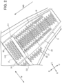
FIG. 2 illustrates one example of a trough of the conveyance apparatus according to the embodiment; -
FIG. 3 illustrates a part of a front surface, on which an article is conveyed, of the trough of the conveyance apparatus according to the embodiment; -
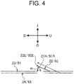
FIG. 4 is an X-X cross-sectional view inFIG. 3 ; -
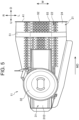
FIG. 5 illustrates the trough of the conveyance apparatus according to the embodiment as viewed from the side of a back surface; -
FIG. 6 illustrates one example of the trough of the conveyance apparatus according to the embodiment; -
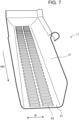
FIG. 7 illustrates one example of an arrangement pattern of a plurality of protrusions on the front surface, on which an article is conveyed, of the trough of the conveyance apparatus according to the embodiment; -
FIG. 8 illustrates one example of the arrangement pattern of the plurality of protrusions on the front surface, on which an article is conveyed, of the trough of the conveyance apparatus according to the embodiment; and -
FIG. 9 illustrates one example of the arrangement pattern of the plurality of protrusions on the front surface, on which an article is conveyed, of the trough of the conveyance apparatus according to the embodiment. - Hereinafter, the present embodiment will be described in detail with reference to the attached drawings. In the following description of the drawings, the same or similar parts are denoted by the same or similar reference symbols. However, note that the drawings are schematic, and ratios of dimensions are different from actual ones. Therefore, specific dimensions and the like are determined in consideration of the following description. Moreover, there may be portions where dimensional relationships or proportions are different among the drawings. In this specification and the drawings, elements having substantially the same function and configuration are denoted by the same reference numerals to omit redundant description, and elements not directly related to the present invention are omitted.
- A conveyance apparatus 1 according to a first embodiment of the present invention will be described below with reference to
FIGS. 1 to 6 . - Although, in the embodiment, a case where the conveyance apparatus 1 is a weighing device that weighs a mass value of an article with a Roberval mechanism will be described in an example, the present invention is not limited to such a case.
- As illustrated in
FIG. 1 , the conveyance apparatus 1 according to the embodiment includes a dispersion table 10,troughs 11,pool hoppers 12, weighinghoppers 13,collection discharge chutes 15, and adrive unit 20. - The dispersion table 10 disperses articles (objects to be measured) falling from a supply device (not illustrated) toward the
troughs 11. - For example, the dispersion table 10 in the embodiment conveys articles radially outward while circumferentially dispersing the articles by being vibrated by a vibrating mechanism (not illustrated). Note that the dispersion table 10 is not limited to such configuration, and may be a mechanism that conveys articles toward the
troughs 11 by rotationally driving around a vertically extending rotation axis C. In other words, the dispersion table 10 may have any configuration as long as the dispersion table 10 has a function of conveying such articles toward thetroughs 11. - For example, such articles include soft and sticky food such as raw chicken. The articles are, however, not limited thereto. Specifically, the dispersion table 10 can convey any article such as fruit including prunes and sugar-coated candies.
- The
troughs 11 receives articles from the outside, and conveys the articles in a conveyance direction from upstream to downstream. In the embodiment, thetroughs 11 supply the articles supplied from the dispersion table 10 to thepool hoppers 12 each provided downstream. Thedrive unit 20 drives thetroughs 11. - The
pool hoppers 12 temporarily hold the articles supplied from thetroughs 11.Gate 12a are provided at lower portions of thepool hoppers 12. The objects to be measured held in thepool hoppers 12 are discharged to the weighinghoppers 13 provided below thegates 12a by opening/closing operations of thegates 12a. - The weighing
hoppers 13 temporarily hold the articles discharged by thepool hoppers 12. Gates (not illustrated) are provided at lower portions of the weighinghoppers 13. The articles held in the weighinghoppers 13 are discharged to thecollection discharge chutes 15 provided below the gates by opening/closing operations of the gates. - The
collection discharge chutes 15 collect the articles discharged from the plurality of weighinghoppers 13, and drop the articles downward. - One example of the
troughs 11 of the conveyance apparatus 1 according to the embodiment will be described below with reference toFIGS. 2 to 4 . - As illustrated in
FIG. 2 , each of thetroughs 11 has a plurality ofprotrusions 92 on afront surface 91 on which an article is conveyed. That is, thefront surface 91, on which an article is conveyed, of each of thetroughs 11 is subjected to shutter processing. The shutter processing may be louver processing. Thesurface 91 subjected to the shutter processing has structure in which the other side of each of thetroughs 11 is invisible when thefront surface 91 is viewed from the front and the other side of each of thetroughs 11 is made visible by shifting a viewpoint. - As illustrated in
FIGS. 3 and4 ,openings 91A passing from thefront surface 91 toward aback surface 93 are formed atends 92E on the downstream side of the plurality ofprotrusions 92. - In other words, as illustrated in
FIGS. 3 and4 , each of thetroughs 11 has a first slidingsurface 91 and secondsliding surfaces 92. The first slidingsurface 91 has the plurality ofopenings 91A. The second slidingsurfaces 92 close parts of theopenings 91A, and are located on an inner side I of each of thetroughs 11 than the first slidingsurface 91. - Each of the second
sliding surfaces 92 is continuous with the first slidingsurface 91 on an upstream side U, a left side L, and a right side R of each of the above-describedopenings 91A. - Specifically, as illustrated in
FIG. 3 , each of the secondsliding surfaces 92 has a leftflat surface 92L, a rightflat surface 92R, and an upperflat surface 92U. - Here, as illustrated in
FIG. 3 , the leftflat surface 92L stands from the first slidingsurface 91 toward the inner side I on the left side L of each of theopenings 91A. - As illustrated in
FIG. 3 , the rightflat surface 92R stands from the first slidingsurface 91 toward the inner side I on the right side R of each of theopenings 91A. - As illustrated in
FIG. 3 , the upperflat surface 92U couples the leftflat surface 92L with the rightflat surface 92R. - As illustrated in
FIG. 4 , driving force and the like from thedrive unit 20 slide an article from an upper side U to a lower side D along the first slidingsurface 91 and the upperflat surfaces 92U of the second slidingsurfaces 92 on thefront surface 91, on which an article is conveyed, of each of thetroughs 11. - The protrusions (second sliding surfaces) 92 are provided on the
front surface 91, on which an article is conveyed, of each of thetroughs 11. Such configuration can reduce an area of contact between a highly sticky article and thefront surface 91, reduce adhesion of the article to thefront surface 91, and enable appropriate conveyance control. - Even when a highly sticky article comes into contact with the
front surface 91, air flows in from each of theopenings 91A. A layer of air can thus be formed between thefront surface 91 and the article, and atmospheric pressure is applied to also a portion where thesurface 91 and the article are in contact with each other. This configuration can reduce adhesion of the article to thefront surface 91. - The
end 92E restricts backward movement of the article, so that the article is smoothly conveyed downstream. - As illustrated in
FIG. 2 , a density D1 of theprotrusions 92 in a first region A near anend 11E on the downstream side of each of thetroughs 11 may be smaller than a density D2 of theprotrusions 92 in a second region B, which is located on the upstream side of the region A near theend 11E on the downstream side of each of thetroughs 11. - Here, the density D1 may be made smaller than the density D2 by making the distances between the
protrusions 92 in the first region A longer than the distances between theprotrusions 92 in the second region B. - The density D1 may be made smaller than the density D2 by providing a region with no protrusions 92 (region C1 in example of
FIG. 2 ) in a part of the first region A. - According to such configuration, a conveying speed on the
front surface 91 of each of thetroughs 11 is inhibited by intentionally deteriorating article conveying performance in the region A near theend 11E on the downstream side of each of thetroughs 11. The configuration can prevent articles from excessively flowing. The configuration decelerates an article at an end portion of each of thetroughs 11, so that unintentional falling of the article to each of thepool hoppers 12 can be reduced. - For example, when an elastic article such as meat is conveyed, a contact area is increased with deformation of the article in the region A near the
end 11E on the downstream side of each of thetroughs 11, so that the conveying speed is inhibited. - A height H (see
FIG. 4 ) of each of theprotrusions 92 in the first region A of each of thetroughs 11 may be lower than a height H of each of theprotrusions 92 in the second region B of each of thetroughs 11. - Such configuration can reduce an amount of air flowing from each of the
openings 91A when a highly sticky article comes into contact with thefront surface 91 in the first region A. A layer of air between thefront surface 91 and the article is thus made thin. In the configuration, the adhesion of the article to thefront surface 91 remains, and an article conveying speed can be inhibited as compared with the case of the second region B. This configuration prevents the article from excessively flowing. As a result, unintentional falling of the article to each of thepool hoppers 12 can be reduced. - As illustrated in
FIG. 2 , the conveyance apparatus 1 according to the embodiment may haveupright portions 21. Theupright portions 21 stand upright from thefront surface 91 at both ends in a width direction W intersecting a conveyance direction MD of each of thetroughs 11. Here, as illustrated inFIG. 2 , each of theupright portions 21 may have a plurality ofprotrusions 22 on an innerfront surface 23 in the width direction W. - As illustrated in
FIGS. 3 and4 ,openings 21A passing from thefront surface 23 toward aback surface 24 may be formed at ends 22E on the downstream side of the plurality ofprotrusions 22 of each of theupright portions 21. - In other words, as illustrated in
FIGS. 3 and4 , each of thetroughs 11 has a first slidingsurface 23 and second sliding surfaces 22. The first slidingsurface 23 has the plurality ofopenings 21A. The second slidingsurfaces 22 close parts of theopenings 21A, and are located on the inner side I of each of thetroughs 11 than the first slidingsurface 23. - Each of the second sliding
surfaces 22 is continuous with the first slidingsurface 23 on an upstream side U, a left side L, and a right side R of each of the above-describedopenings 21A. - Specifically, as illustrated in
FIG. 3 , each of the second slidingsurfaces 22 has a leftflat surface 22L, a rightflat surface 22R, and an upperflat surface 22U. - Here, as illustrated in
FIG. 3 , the leftflat surface 22L stands from the first slidingsurface 23 toward the inner side I on the left side L of each of theopenings 21A. - As illustrated in
FIG. 3 , the rightflat surface 22R stands from the first slidingsurface 23 toward the inner side I on the right side R of each of theopenings 21A. - As illustrated in
FIG. 3 , the upperflat surface 22U couples the leftflat surface 22L with the rightflat surface 22R. - According to such configuration, the article conveying speed can be more reliably controlled by providing the
protrusions 22 on each of theupright portions 21 with which a side surface of the article comes in contact. - As illustrated in
FIG. 5 , the conveyance apparatus 1 according to the embodiment may include reinforcingmembers 51 on the side of theback surface 93 in the first region A near theend 11E on the downstream side of each of thetroughs 11. As illustrated inFIG. 2 , noprotrusions 92 may be provided in the region C1 on the front surface opposite to the region on theback surface 93 where each of the reinforcingmembers 51 is provided. - As illustrated in
FIG. 5 , each of the reinforcingmember 51 may extend to theback surface 24 of each of theupright portions 21. In such a case, as illustrated inFIG. 2 , noprotrusions 92 may be provided in the region C2 on the front surface opposite to the region on theback surface 24 where each of the reinforcingmembers 51 is provided. - Such configuration can increase the strength of each of the
troughs 11 while making the density D1 smaller than the density D2. - Here, the reinforcing
member 51 provided on the side of theback surface 93 in the first region A and the reinforcingmember 51 provided on the side of theback surface 24 of each of theupright portions 21 may be integrated, or may be formed of different members. - As illustrated in
FIG. 5 , the conveyance apparatus 1 according to the embodiment may includeattachments 31 and joints 32. - As illustrated in
FIG. 6 , each of theattachments 31 extends in the conveyance direction MD, and includes a member having a U-shaped cross section with an upper side open. For example, as illustrated inFIGS. 2 and6 , each of theattachments 31 is attached to a region of each of thetroughs 11 with noprotrusions 92. - Each of the
joints 32 is attached to each of theattachments 31, and is detachable from a main body of the conveyance apparatus 1. For example, as illustrated inFIG. 6 , each of thejoints 32 is attached to alower surface 31D of each of theattachments 31. As illustrated inFIG. 5 , each of thejoints 32 has a circular shape corresponding to an attachment (not illustrated) of the main body of the conveyance apparatus 1. - In such configuration, each of the
attachments 31 is attached to a region of each of thetroughs 11 with noprotrusions 92. Each of thetroughs 11 can thus be attached to the main body of the conveyance apparatus 1 without influencing the arrangement of theprotrusions 92 in each of thetroughs 11. - As illustrated in
FIG. 6 , the conveyance apparatus 1 according to the embodiment may includeribs 41 bent toward the side of theback surface 93 at theend 11E on the downstream side of each of thetroughs 11. As illustrated inFIG. 6 , each of theribs 41 may extend to the end on the downstream side of each of theupright portions 21. Such configuration can further enhance the strength of each of thetroughs 11. - In the conveyance apparatus 1 according to the embodiment, as illustrated in
FIGS. 7 to 9 , the plurality ofprotrusions 92 may be arranged along the conveyance direction MD on thefront surface 91. - For example, as illustrated in
FIG. 7 , the plurality ofprotrusions 92 may be arranged in a plurality of lines parallel to the conveyance direction MD on thefront surface 91. Although, in an example ofFIG. 7 , two lines are formed by the arrangement of theprotrusions 92, three or more lines may be formed. - In the conveyance apparatus 1 according to the embodiment, as illustrated in
FIG. 8 , the numbers of theprotrusions 92 arranged along the width direction W may be different from each other depending on the positions in the conveyance direction MD. Although, in an example ofFIG. 8 , positions where oneprotrusion 92 is arranged along the width direction W and positions where twoprotrusions 92 are arranged along the width direction W are mixed along the conveyance direction MD, the number of theprotrusions 92 arranged along the width direction W is not limited to such numbers, and any number ofprotrusions 92 may be arranged. - In the conveyance apparatus 1 according to the embodiment, as illustrated in
FIG. 9 , the numbers of theprotrusions 92 arranged along the width direction W may be the same as each other regardless of the positions in the conveyance direction MD. Here, as illustrated inFIG. 9 , the positions of theprotrusions 92 in the width direction W may be different from each other depending on the positions in the conveyance direction MD. Although, in an example ofFIG. 9 , a case in which twoprotrusions 92 are arranged along the width direction W has been described, the present invention is not limited to such a case. The present invention is applied to a case where three ormore protrusions 92 are arranged along the width direction W. - The embodiment of the present invention has been described in detail above. It is obvious to a person skilled in the art that the present invention is not limited to the embodiment in the present specification. The present invention can be carried out in aspects corrected and altered without departing from the gist and scope of the present invention in the claims. Therefore, the present specification is intended for exemplificative description and thus does not have any limitative meanings to the present invention.
-
- 1
- conveyance apparatus
- 10
- dispersion table
- 11
- trough
- 12
- pool hopper
- 13
- weighing hopper
- 15
- collection discharge chute
- 20
- drive unit
- 21
- upright portion
- 21A, 91A
- opening
- 22
- protrusion
- 23
- front surface
- 24, 93
- back surface
- 31
- attachment
- 32
- joint
- 41
- rib
- 51
- reinforcing member
- 91
- front surface (first sliding surface)
- 92
- protrusion (second sliding surface)
Claims (9)
- A conveyance apparatus comprising:a trough that receives an article from an outside and conveys the article in a conveyance direction from upstream to downstream; anda drive unit that drives the trough, whereinthe trough includes a plurality of protrusions on a front surface on which the article is conveyed, andan opening passing from the front surface to a back surface is formed at an end on a downstream side of the plurality of protrusions.
- The conveyance apparatus according to claim 1, wherein
a density of the protrusions in a first region near an end on a downstream side of the trough is smaller than a density of the protrusions in a second region located on an upstream side of a region near an end on a downstream side of the trough. - The conveyance apparatus according to claim 1 or claim 2, wherein
heights of the protrusions in a first region near an end on a downstream side of the trough are smaller than heights of the protrusions in a second region located on an upstream side of a first region near an end on the downstream side of the trough. - The conveyance apparatus according to any one of claims 1 to 3, comprising an upright portion that stands upright from the front surface at both ends in a width direction intersecting the conveyance direction of the trough, whereinthe upright portion includes a plurality of protrusions on an inner front surface in the width direction, andan opening passing from a front surface to a back surface is formed at an end on a downstream side of a plurality of protrusions of the upright portion.
- The conveyance apparatus according to any one of claims 1 to 4, comprising a reinforcing member on a side of the back surface in a first region near an end on the downstream side of the trough, wherein
the protrusions are not provided in a region on the front surface opposite to a region on the back surface where the reinforcing member is provided. - The conveyance apparatus according to any one of claims 1 to 5, comprising:an attachment having a U-shaped cross section, the attachment being attached to a region where the protrusions in the trough are not provided, extending in the conveyance direction, and having an upper side open; anda joint that is attached to a lower surface of the attachment and detachable from a main body of the conveyance apparatus.
- The conveyance apparatus according to any one of claims 1 to 6, comprising a rib bent toward the side of the back surface at an end on the downstream side of the trough.
- The conveyance apparatus according to any one of claims 1 to 7, whereinthe plurality of protrusions are arranged in aplurality of lines parallel to the conveyance direction.
- A conveyance apparatus comprising:a trough that receives an article from an outside and conveys the article in a conveyance direction from upstream to downstream; anda drive unit that drives the trough, whereinthe trough includes:a first sliding surface having a plurality of openings; anda second sliding surface that closes a part of each of the openings and is located at an inner position of the trough than the first sliding surface, andthe second sliding surface is continuous with the first sliding surface on an upstream side, a left side, and a right side of each of the openings.
Applications Claiming Priority (1)
| Application Number | Priority Date | Filing Date | Title |
|---|---|---|---|
| JP2021141770A JP7765067B2 (en) | 2021-08-31 | 2021-08-31 | Conveyor |
Publications (3)
| Publication Number | Publication Date |
|---|---|
| EP4140918A1 true EP4140918A1 (en) | 2023-03-01 |
| EP4140918B1 EP4140918B1 (en) | 2025-10-22 |
| EP4140918C0 EP4140918C0 (en) | 2025-10-22 |
Family
ID=82838967
Family Applications (1)
| Application Number | Title | Priority Date | Filing Date |
|---|---|---|---|
| EP22188632.8A Active EP4140918B1 (en) | 2021-08-31 | 2022-08-03 | Conveyance apparatus |
Country Status (5)
| Country | Link |
|---|---|
| US (1) | US12084285B2 (en) |
| EP (1) | EP4140918B1 (en) |
| JP (1) | JP7765067B2 (en) |
| CN (1) | CN115724122B (en) |
| BR (1) | BR102022016191A2 (en) |
Families Citing this family (2)
| Publication number | Priority date | Publication date | Assignee | Title |
|---|---|---|---|---|
| WO2021210093A1 (en) * | 2020-04-15 | 2021-10-21 | 大和製衡株式会社 | Conveyor and combination weigher equipped with same |
| JP7597357B2 (en) * | 2020-11-12 | 2024-12-10 | 株式会社イシダ | Combination Weighing Device |
Citations (5)
| Publication number | Priority date | Publication date | Assignee | Title |
|---|---|---|---|---|
| WO2007147419A1 (en) * | 2006-06-19 | 2007-12-27 | Scanvaegt International A/S | Multihead weigher and method of operating such multihead weigher |
| JP2013000684A (en) * | 2011-06-17 | 2013-01-07 | Satake Corp | Chute for optical sorter |
| WO2014067533A1 (en) * | 2012-11-02 | 2014-05-08 | Marel A/S | An anti-sticking surface plate structure to be used as a low-friction based material in a food processing apparatus and method for its manufacture |
| WO2018139127A1 (en) * | 2017-01-27 | 2018-08-02 | 大和製衡株式会社 | Vibrating feeder and item supply device using same |
| JP2020023386A (en) | 2018-08-07 | 2020-02-13 | 株式会社イシダ | Conveying device and combination weighing device having the same |
Family Cites Families (9)
| Publication number | Priority date | Publication date | Assignee | Title |
|---|---|---|---|---|
| AU543793B2 (en) * | 1981-09-09 | 1985-05-02 | K.K. Ishida Koki Seisakusho | Preventing adhesion of weighed material |
| US5967294A (en) * | 1997-04-23 | 1999-10-19 | Fmc Corporation | High stroke, highly damped spring system for use with vibratory feeders |
| JP2006199424A (en) * | 2005-01-20 | 2006-08-03 | Ishida Co Ltd | Conveying device and combination weighing device provided with the same |
| US7216757B1 (en) * | 2005-12-15 | 2007-05-15 | Fmc Technologies, Inc. | Differential motion conveyor |
| US9776805B2 (en) * | 2013-05-13 | 2017-10-03 | Key Technology, Inc. | Linear motion conveyor |
| CN104495197A (en) * | 2014-12-08 | 2015-04-08 | 重庆永健食品集团股份有限公司 | Food conveying device and discharging chute thereof |
| JP6465356B2 (en) * | 2015-07-02 | 2019-02-06 | 大和製衡株式会社 | Hopper and combination scale equipped with the same |
| CA2993932C (en) * | 2015-08-04 | 2019-02-26 | Key Technology, Inc. | Improved linear motion conveyor |
| JP6711264B2 (en) * | 2016-12-27 | 2020-06-17 | 三菱自動車工業株式会社 | scrap shooting |
-
2021
- 2021-08-31 JP JP2021141770A patent/JP7765067B2/en active Active
-
2022
- 2022-08-03 EP EP22188632.8A patent/EP4140918B1/en active Active
- 2022-08-15 BR BR102022016191-7A patent/BR102022016191A2/en unknown
- 2022-08-19 US US17/821,132 patent/US12084285B2/en active Active
- 2022-08-26 CN CN202211032617.2A patent/CN115724122B/en active Active
Patent Citations (5)
| Publication number | Priority date | Publication date | Assignee | Title |
|---|---|---|---|---|
| WO2007147419A1 (en) * | 2006-06-19 | 2007-12-27 | Scanvaegt International A/S | Multihead weigher and method of operating such multihead weigher |
| JP2013000684A (en) * | 2011-06-17 | 2013-01-07 | Satake Corp | Chute for optical sorter |
| WO2014067533A1 (en) * | 2012-11-02 | 2014-05-08 | Marel A/S | An anti-sticking surface plate structure to be used as a low-friction based material in a food processing apparatus and method for its manufacture |
| WO2018139127A1 (en) * | 2017-01-27 | 2018-08-02 | 大和製衡株式会社 | Vibrating feeder and item supply device using same |
| JP2020023386A (en) | 2018-08-07 | 2020-02-13 | 株式会社イシダ | Conveying device and combination weighing device having the same |
Also Published As
| Publication number | Publication date |
|---|---|
| BR102022016191A2 (en) | 2023-03-07 |
| US12084285B2 (en) | 2024-09-10 |
| JP2023035142A (en) | 2023-03-13 |
| CN115724122A (en) | 2023-03-03 |
| EP4140918B1 (en) | 2025-10-22 |
| CN115724122B (en) | 2025-12-12 |
| US20230069688A1 (en) | 2023-03-02 |
| JP7765067B2 (en) | 2025-11-06 |
| EP4140918C0 (en) | 2025-10-22 |
Similar Documents
| Publication | Publication Date | Title |
|---|---|---|
| EP4140918B1 (en) | Conveyance apparatus | |
| EP3431937B1 (en) | Combination weighing device | |
| EP4001860B1 (en) | Combination weighing apparatus | |
| US11975923B2 (en) | Article retaining device and supporting body | |
| CN116767817B (en) | Combined metering device | |
| EP3431936B1 (en) | Combination weighing device | |
| EP3892969A1 (en) | Combination weighing device | |
| AU2011101636A4 (en) | Combination weighing apparatus | |
| DE60322990D1 (en) | Guide channels for weighing cups and chutes | |
| US20190162586A1 (en) | Hopper and combination weighing device equipped therewith | |
| JP2018052740A (en) | Collective chute and combination weighing device having the same | |
| EP2094589B1 (en) | Product transport surface comprising grooves | |
| US20210070560A1 (en) | Timing hopper and combination weighing device | |
| EP4174456A1 (en) | Article processing apparatus | |
| JP2002173210A (en) | Weighing device with article collection mechanism | |
| JP2024025187A (en) | Conveying device and combination weighing system | |
| JP6694997B1 (en) | Dusting device | |
| US20240308772A1 (en) | Combination weighing apparatus | |
| JP7650605B2 (en) | Hopper and combination weigher equipped with same | |
| JP2009080027A (en) | Wall member and weighing device including the same | |
| BR102021021850B1 (en) | COMBINATION WEIGHING DEVICE | |
| WO2018056321A1 (en) | Collecting chute and combination weighing device provided with same | |
| CN113710995A (en) | Combined scale |
Legal Events
| Date | Code | Title | Description |
|---|---|---|---|
| PUAI | Public reference made under article 153(3) epc to a published international application that has entered the european phase |
Free format text: ORIGINAL CODE: 0009012 |
|
| STAA | Information on the status of an ep patent application or granted ep patent |
Free format text: STATUS: REQUEST FOR EXAMINATION WAS MADE |
|
| 17P | Request for examination filed |
Effective date: 20220803 |
|
| AK | Designated contracting states |
Kind code of ref document: A1 Designated state(s): AL AT BE BG CH CY CZ DE DK EE ES FI FR GB GR HR HU IE IS IT LI LT LU LV MC MK MT NL NO PL PT RO RS SE SI SK SM TR |
|
| GRAP | Despatch of communication of intention to grant a patent |
Free format text: ORIGINAL CODE: EPIDOSNIGR1 |
|
| STAA | Information on the status of an ep patent application or granted ep patent |
Free format text: STATUS: GRANT OF PATENT IS INTENDED |
|
| RIC1 | Information provided on ipc code assigned before grant |
Ipc: B65G 47/14 20060101ALI20250416BHEP Ipc: B65G 11/16 20060101AFI20250416BHEP |
|
| INTG | Intention to grant announced |
Effective date: 20250521 |
|
| GRAS | Grant fee paid |
Free format text: ORIGINAL CODE: EPIDOSNIGR3 |
|
| GRAA | (expected) grant |
Free format text: ORIGINAL CODE: 0009210 |
|
| STAA | Information on the status of an ep patent application or granted ep patent |
Free format text: STATUS: THE PATENT HAS BEEN GRANTED |
|
| AK | Designated contracting states |
Kind code of ref document: B1 Designated state(s): AL AT BE BG CH CY CZ DE DK EE ES FI FR GB GR HR HU IE IS IT LI LT LU LV MC MK MT NL NO PL PT RO RS SE SI SK SM TR |
|
| REG | Reference to a national code |
Ref country code: CH Ref legal event code: F10 Free format text: ST27 STATUS EVENT CODE: U-0-0-F10-F00 (AS PROVIDED BY THE NATIONAL OFFICE) Effective date: 20251022 Ref country code: GB Ref legal event code: FG4D |
|
| REG | Reference to a national code |
Ref country code: DE Ref legal event code: R096 Ref document number: 602022023357 Country of ref document: DE |
|
| REG | Reference to a national code |
Ref country code: IE Ref legal event code: FG4D |
|
| U01 | Request for unitary effect filed |
Effective date: 20251023 |
|
| U07 | Unitary effect registered |
Designated state(s): AT BE BG DE DK EE FI FR IT LT LU LV MT NL PT RO SE SI Effective date: 20251030 |
|
| PG25 | Lapsed in a contracting state [announced via postgrant information from national office to epo] |
Ref country code: ES Free format text: LAPSE BECAUSE OF FAILURE TO SUBMIT A TRANSLATION OF THE DESCRIPTION OR TO PAY THE FEE WITHIN THE PRESCRIBED TIME-LIMIT Effective date: 20251022 |
|
| PG25 | Lapsed in a contracting state [announced via postgrant information from national office to epo] |
Ref country code: NO Free format text: LAPSE BECAUSE OF FAILURE TO SUBMIT A TRANSLATION OF THE DESCRIPTION OR TO PAY THE FEE WITHIN THE PRESCRIBED TIME-LIMIT Effective date: 20260122 |
|
| PG25 | Lapsed in a contracting state [announced via postgrant information from national office to epo] |
Ref country code: HR Free format text: LAPSE BECAUSE OF FAILURE TO SUBMIT A TRANSLATION OF THE DESCRIPTION OR TO PAY THE FEE WITHIN THE PRESCRIBED TIME-LIMIT Effective date: 20251022 |
|
| PG25 | Lapsed in a contracting state [announced via postgrant information from national office to epo] |
Ref country code: RS Free format text: LAPSE BECAUSE OF FAILURE TO SUBMIT A TRANSLATION OF THE DESCRIPTION OR TO PAY THE FEE WITHIN THE PRESCRIBED TIME-LIMIT Effective date: 20260122 |
|
| PG25 | Lapsed in a contracting state [announced via postgrant information from national office to epo] |
Ref country code: IS Free format text: LAPSE BECAUSE OF FAILURE TO SUBMIT A TRANSLATION OF THE DESCRIPTION OR TO PAY THE FEE WITHIN THE PRESCRIBED TIME-LIMIT Effective date: 20260222 |
|
| PG25 | Lapsed in a contracting state [announced via postgrant information from national office to epo] |
Ref country code: PL Free format text: LAPSE BECAUSE OF FAILURE TO SUBMIT A TRANSLATION OF THE DESCRIPTION OR TO PAY THE FEE WITHIN THE PRESCRIBED TIME-LIMIT Effective date: 20251022 |