EP4140883B1 - Verriegelungszustandsdetektionssystem, verfahren und vorrichtungen - Google Patents
Verriegelungszustandsdetektionssystem, verfahren und vorrichtungen Download PDFInfo
- Publication number
- EP4140883B1 EP4140883B1 EP22185709.7A EP22185709A EP4140883B1 EP 4140883 B1 EP4140883 B1 EP 4140883B1 EP 22185709 A EP22185709 A EP 22185709A EP 4140883 B1 EP4140883 B1 EP 4140883B1
- Authority
- EP
- European Patent Office
- Prior art keywords
- pawl
- latch
- various embodiments
- assembly
- transducer
- Prior art date
- Legal status (The legal status is an assumption and is not a legal conclusion. Google has not performed a legal analysis and makes no representation as to the accuracy of the status listed.)
- Active
Links
Images


Classifications
-
- B—PERFORMING OPERATIONS; TRANSPORTING
- B64—AIRCRAFT; AVIATION; COSMONAUTICS
- B64D—EQUIPMENT FOR FITTING IN OR TO AIRCRAFT; FLIGHT SUITS; PARACHUTES; ARRANGEMENT OR MOUNTING OF POWER PLANTS OR PROPULSION TRANSMISSIONS IN AIRCRAFT
- B64D9/00—Equipment for handling freight; Equipment for facilitating passenger embarkation or the like
- B64D9/003—Devices for retaining pallets or freight containers
-
- H—ELECTRICITY
- H04—ELECTRIC COMMUNICATION TECHNIQUE
- H04B—TRANSMISSION
- H04B1/00—Details of transmission systems, not covered by a single one of groups H04B3/00 - H04B13/00; Details of transmission systems not characterised by the medium used for transmission
- H04B1/02—Transmitters
- H04B1/04—Circuits
Definitions
- the present disclosure relates generally to cargo handling systems and, more particularly, to actuator assemblies and latch assemblies for cargo handling systems.
- Cargo handling systems for aircraft typically include various tracks and rollers disposed on a cargo deck that spans the length of a cargo compartment. Cargo may be loaded from an entrance of the aircraft and transported by the cargo system to forward or aft locations, depending upon the configuration of the aircraft.
- Cargo handling systems such as, for example, those used on aircraft for transport of heavy containerized cargo or pallets, also referred to herein as unit load devices (ULDs), typically include restraints to lock the ULDs in the cargo compartment. Typical latches for ULDs are operated manually, which lend themselves to potential user error.
- EP 3 556 656 relates to a cargo restraint sensor system, wherein sensors are configured to sense information relating to cargo latches, wireless communication circuits are configured to transmit the sensed information to a central controller, and batteries are powering the wireless communication circuits.
- a latch assembly is provided in claim 1.
- the pawl assembly comprises an inner pawl and an outer pawl.
- the inner pawl may be configured to activate the transducer in response to the pawl assembly reaching the restrained state.
- the transducer may comprise a piezoelectric button.
- the transducer may comprise an electric generator configured to convert one of linear or rotary motion into the electrical energy.
- the communications module may include a transmitter, the transmitter configured to transmit a wireless signal including a unique identifier of the latch assembly.
- FIGS. 1A and 1B a schematic view of an aircraft 10 having a cargo deck 12 located within a cargo compartment 14 is illustrated, in accordance with various embodiments.
- the aircraft 10 may comprise a cargo load door 16 located, for example, at a forward end of the aircraft 10 and configured to rotate upward (as illustrated in FIG. 1A ) or sideways to expose an opening 18 that provides access to the cargo compartment 14.
- a second cargo load door 17 may be located at other portions of the aircraft 10, such as, for example, at an aft end of the aircraft 10 and configured to rotate downward (as illustrated in FIG. 1B ) and provide a second opening 19 to gain access to the cargo compartment 14.
- the one or more trays 20 provide a support structure for which a platform 26 may transit along a length of the aircraft 10 between the fore end and the aft end and carry a ULD or some other form of cargo carrier, such as, for example, a container of a size typically used for ocean-going transport by ship or truck.
- a cargo load 28 of any size or shape which may include objects within containers or ULDs or objects not within containers or ULDs, such as, for example, automobiles or the like, will be considered herein as configured for transport on the platform 26.
- the one or more trays 20, during loading or unloading of the cargo load 28, may be connected to a loading structure 30 which, in various embodiments, may comprise one or more trays or tracks 32 that correspond to the one or more trays 20 extending along the cargo deck 12 of the aircraft 10.
- the loading structure 30 may be attached to an elevated structure, such as, for example, a truck 34 (as illustrated in FIG. 1B ) or a scissor lift or a loading dock or the like, such that the one or more trays 20 and the loading structure 30 are located substantially at the same elevation and configured to transition a platform 26 either onto or off from the one or more trays 20.
- a first cargo load 36 may be transitioned from the loading structure 30, through the opening 18 and onto the one or more trays 20, and then along the one or more trays 20 to the aft end of the aircraft, where the first cargo load 36 is secured for transport. This may be followed by a second cargo load 38, a third cargo load 40 and so on until the cargo deck 12 is filled to a desired capacity with cargo.
- each cargo load such as, for example, the first cargo load 36, the second cargo load 38 and the third cargo load 40 are unloaded from the aircraft 10 in similar fashion, but in a reverse sequence to the loading procedure.
- the aircraft 10 may include a restraint assembly as described herein and in accordance with various embodiments.
- FIG. 2 a portion of a cargo handling system 200 is illustrated, in accordance with various embodiments.
- the cargo handling system 200 is illustrated with reference to an XYZ coordinate system, with the X-direction extending longitudinally in an aft direction (and defining a longitudinal direction), the Y-direction extending perpendicular to the X-direction (and defining a lateral direction) and the Z-direction extending vertically, each direction being with respect to an aircraft in which the cargo handling system 200 is positioned, such as, for example, the aircraft 10 described above with reference to FIGS. 1A and 1B .
- the cargo handling system 200 may define at least one tray or track 210 extending longitudinally in the aft direction (i.e., the X-direction).
- the tray 210 may include a plurality of rollers 212, each roller extending laterally from a first lateral side of the tray 210 to a second lateral side of the tray 210.
- the cargo handling system 200 includes a platform 226 (or a plurality of platforms), such as, for example, the platform 26 described above with reference to FIGS. 1A and 1B .
- the platform 226 is configured to support a cargo load 228, which may include containerized or non-containerized cargo. As illustrated in FIG.
- the tray 210 may include a substantially level surface throughout the length of the aircraft, though a portion of the tray 210 may be curved upward, particularly toward the aft end of the aircraft where the fuselage tends to curve upward at its base in order to facilitate takeoff and landing.
- the cargo handling system 200 may further comprise a latch assembly 300 and a cargo control unit 305.
- the cargo control unit 305 may be in electrical communication with the latch assembly 300.
- the latch assembly 300 may be configured to lock the platform 226 in place.
- the control unit 305 may be configured to transition the latch assembly 300 from a locked position to an unlocked position, or vice versa.
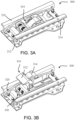
- FIG. 3A and 3B a perspective view of a latch assembly 300 installed within a tray 210 in a retracted or unlatched state ( FIG.3A ) and a restrained or latching state ( FIG. 3B ), in accordance with various embodiments.
- the latch assembly 300 comprises a pawl assembly 310 operably coupled to a latch housing 320.
- the latch housing 320 of the latch assembly 300 may be coupled to the tray 210 at a first longitudinal end 212 of the tray 210 and a second longitudinal end 214 of the tray 210.
- the pawl assembly 310 is configured to transition from the un-restrained state ( FIG. 3A ) to the restrained state ( FIG.
- the restrained state ( FIG. 3B ) is utilized during transport of cargo (e.g., a cargo load 28 from FIGs. 1A and 1B ) to restrain a platform (e.g., platform 226 from FIG. 2 ) or the like.
- cargo e.g., a cargo load 28 from FIGs. 1A and 1B
- platform e.g., platform 226 from FIG. 2
- Typical latch status detection systems are manual inspections, which may be time consuming and may be subject to inspector error.
- the latch assembly 300 further comprises a latch state detection system 330.
- the latch state detection system 330 is configured to automatically detect when a latch assembly 300 is in a restrained state ( FIG. 3B ).
- the latch state detection system 330 of the latch assembly 300 is further configured to transmit, in response to being activated, a signal to indicate the latch assembly 300 is in a fully restrained state ( FIG. 3B ).
- the pawl assembly 310 comprises an outer pawl or latch 312 and an inner pawl or latch 314.
- the inner pawl 314 is configured to restrain a first platform (e.g., platform 226) and the outer pawl 312 is configured to restrain a second platform (e.g., an adjacent platform in accordance with platform 226) during transport of cargo (e.g., cargo load 28 from FIGs. 1A and 1B ).
- cargo e.g., cargo load 28 from FIGs. 1A and 1B
- the pawl assembly 310 transitions from the un-restrained state to the restrained state once a first platform is in place.
- one of the outer pawl 312 or the inner pawl 314 will engage the first platform and the remaining pawl will remain unengaged until a second platform is loaded and abuts the remaining pawl in accordance with various embodiments.
- the latch state is often detected one row at a time, in accordance with various embodiments.
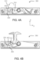
- FIGs. 4A and 4B a cross-sectional view of a latch assembly 300 with the latch state detection system 330 is illustrated transitioning from an un-restrained state ( FIG.4A ) to a restrained state ( FIG. 4B ), in accordance with various embodiments.
- the latch state detection system 330 is configured to generate an electrical signal in response to mechanical motion as described further herein.
- the latch state detection system 330 is further configured to transmit a latch identifier (i.e., a unique identifier in accordance with the Institute of Electrical and Electronics Engineers (IEEE) 802.15.1 or 802.15.4, or the like) to a control unit of a cargo handling system (e.g., control unit 305 from FIG. 2 ).
- the latch identifier transmitted to the control unit provides an indication to the control unit that the latch assembly 300 that is associated with the respective unique identifier is in a fully restrained state (i.e., an acceptable state for transport).
- the latch state detection system 330 comprises a transducer 402 and a communications module 404.
- the transducer 402 is configured to convert mechanical energy to electrical energy.
- the transducer 402 is a piezoelectric button 406.
- the transducer 402 in response to being compressed (e.g., by a notch 313 of inner pawl 314), the transducer 402 generates an electrical charge.
- use of the inner pawl 314 as an activating device of the latch state detection system 330 may provide a better indication of the pawl assembly 310 being in a fully restrained state ( FIG.
- a "fully restrained state" of the pawl assembly 310 refers to both the outer pawl 312 and the inner pawl 314 being fully deployed and in a position to engage / restrain a platform 226 or the like.
- the "fully restrained state” is illustrated in FIG. 4B .
- the communications module 404 is configured to receive the electrical charge generated from the transducer 402 (e.g., via a conductive wire or the like). In response to receiving the electrical charge, the communications module 404 is powered and configured to transmit a signal to a control unit (e.g., control unit 305) of a cargo handling system (e.g., cargo handling system 200 of FIG. 2 ) as described previously herein.
- a control unit e.g., control unit 305
- cargo handling system e.g., cargo handling system 200 of FIG. 2
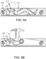
- the transducer 402 may be oriented in a vertical direction (i.e., the Z-direction).
- the present disclosure is not limited in this regard.
- the transducer 402 of the latch state detection system 330 may be oriented in a horizontal direction (e.g., the Y-direction) and still be within the scope of this disclosure.
- 5A and 5B may provide an additional advantage from the latch state detection system 330 in that the notch 313 of the inner pawl 314 cannot be pushed back on from the transducer 402 to transition the pawl assembly 310 to a state that is less than fully deployed in the horizontal configuration ( FIGs. 5A and 5B ) relative to the vertical configuration ( FIGs. 4A and 4B ).
- the latch assembly 600 comprises a transducer 602.
- the transducer 602 is configured to convert mechanical energy to electrical energy in a similar manner to transducer 402. However, the transducer 602 is configured to convert rotary motion to electrical energy as described further herein.
- the latch state detection system 630 further comprises a ratchet 640 including a gear 642 and a pawl 644, a shaft 650, a torsion spring 660, and a link 670.
- the gear 642 is coupled to the shaft 650 of the latch state detection system 630 and configured to rotate with the shaft 650.
- the link 670 is coupled to the shaft 650 and configured to rotate with the shaft 650 about a shaft axis in response to transitioning from an un-restrained state to a restrained state or vice versa as described further herein.
- the link 670 is coupled to the shaft 650 at a proximal end of the link 670 and the link is coupled to a flange 315 of the inner pawl 314 at a distal end of the link 670.
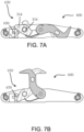
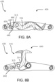
- FIGs. 7A, 7B , 8A, and 8B cross-sectional views of a latch assembly 600 with a latch state detection system 630 with a pawl assembly 310 in an un-restrained state ( FIG. 7A , FIG. 8A ) and a fully restrained state ( FIG. 7B , FIG. 8B ) are illustrated, in accordance with various embodiments.
- the inner pawl 314 is coupled to an inner pawl shaft 316 and configured to rotate with the inner pawl shaft 316 about an axis defined by the inner pawl shaft 316.
- the link 670 In response to the inner pawl 314 rotating in a first direction (e.g., counterclockwise) about the inner pawl axis, the link 670 causes the shaft 650 to rotate in an opposite direction (e.g., clockwise) about the link axis as shown in FIGs. 7A and 7B .
- the torsion spring 660 from FIG. 6 is loaded until a notch 313 of the inner pawl 314 contacts and rotates that pawl 644 of the ratchet 640, which releases gear 642 from the pawl 644 (as shown in FIG. 8B ).
- the shaft 650 rotates back due to the torsion spring 660 being loaded.
- the transducer 602 from FIG. 6 is an electric generator configured to convert the rotary motion of the shaft 650 upon release of the gear 642 from the pawl 644 to electrical energy to power a communications module 404 of the latch state detection system 630.
- latch state detection system 630 is illustrated as loading a torsion spring via rotary motion and converting the rotary motion to electrical energy upon release, the latch state detection system 630 is not limited in this regard.
- latch state detection system 630 could be utilized replacing the torsion spring 660 with a tension or compression spring, loading the tension or compression spring by actuation of a bar which compress or extends the spring, and releasing the tension or compression spring via the notch 313 in accordance with various embodiments.
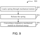
- the same concept as the latch state detection system 630 applies and is illustrated in FIG. 9 .
- the latch state detection system would be configured to load a spring (e.g., torsional, compression, or tension) through mechanical motion (step 902), release the spring in response to a pawl assembly reaching a fully restrained state (e.g., via a notch of an inner pawl) (step 904), and converting a responsive mechanical motion created by the spring (e.g., a responsive rotation or a responsive translation) to electrical energy (e.g., via a transducer) (step 906).
- a spring e.g., torsional, compression, or tension
- electrical energy e.g., via a transducer
- each latch state detection system (e.g., latch state detection systems 330, 430, 630) include a transducer 1014 (e.g., transducer 402, 602) and a transmitter 1012 (e.g., a transmitter disposed in communications module 404).
- a transducer 1014 e.g., transducer 402, 602
- a transmitter 1012 e.g., a transmitter disposed in communications module 404
- control system 1000 comprises a master controller 1002 in operable communication (e.g., wireless) with the latch state detection system 1010 of a latch assembly (e.g., latch assembly 300, 600, or the like).
- controller 1002 may be integrated into a computer system, such as cargo control unit 305 from FIG. 2 .
- controller 1002 may be configured as a central network element or hub to access various systems and components of control system 1000.
- Controller 1002 may comprise a network, computer-based system, and/or software components configured to provide an access point to various systems and components of control system 1000.
- controller 1002 may comprise a processor.
- controller 1002 may be implemented in a single processor.
- controller 1002 may be implemented as and may include one or more processors and/or one or more tangible, non-transitory memories and be capable of implementing logic.
- processors can be a general purpose processor, a digital signal processor (DSP), an application specific integrated circuit (ASIC), a field programmable gate array (FPGA) or other programmable logic device, discrete gate or transistor logic, discrete hardware components, or any combination thereof.
- Controller 1002 may comprise a processor configured to implement various logical operations in response to execution of instructions, for example, instructions stored on a non-transitory, tangible, computer-readable medium configured to communicate with controller 1002.
- System program instructions and/or controller instructions may be loaded onto a non-transitory, tangible computer-readable medium having instructions stored thereon that, in response to execution by a controller, cause the controller to perform various operations.
- non-transitory is to be understood to remove only propagating transitory signals per se from the claim scope and does not relinquish rights to all standard computer-readable media that are not only propagating transitory signals per se.
- the transducer 1014 is configured to convert a mechanical motion that occurs during a process of transitioning a pawl assembly in a latch assembly from an un-restrained state to a fully restrained state to electrical energy to power the transmitter 1012.
- the mechanical motion that triggers the transducer is configured to coincide with the pawl assembly reaching the fully restrained state as described previously herein. In this regard, if the pawl assembly does not reach a fully restrained state, the mechanical motion in its entirety will not occur; thus, not enough electrical energy will provide power to the transmitter 1012 to transmit the signal described previously herein.
- the latch state detection system 1010 is not limited in this regard.
- the transmitter 1012 may be a transceiver, in accordance with various embodiments.
Landscapes
- Engineering & Computer Science (AREA)
- Aviation & Aerospace Engineering (AREA)
- Computer Networks & Wireless Communication (AREA)
- Signal Processing (AREA)
- Arrangements For Transmission Of Measured Signals (AREA)
- Force Measurement Appropriate To Specific Purposes (AREA)
- Measuring Fluid Pressure (AREA)
Claims (5)
- Verriegelungsbaugruppe (300), umfassend:ein Gehäuse (320);eine Sperrklinkenbaugruppe (310), die an das Gehäuse (320) gekoppelt ist, wobei die Sperrklinkenbaugruppe dazu konfiguriert ist, von einem nicht zurückgehaltenen Zustand in einen zurückgehaltenen Zustand überzugehen; undein Verriegelungszustandsdetektionssystem (330), umfassend einen Wandler (402) und ein Kommunikationsmodul (404), wobei der Wandler dazu konfiguriert ist, mechanische Energie von der Sperrklinkenbaugruppe (310), die den zurückgehaltenen Zustand erreicht, in eine elektrische Energie umzuwandeln, die dazu konfiguriert ist, das Kommunikationsmodul (404) mit Strom zu versorgen, wobei das Kommunikationsmodul (404) als Reaktion darauf, dass die elektrische Energie empfangen wird, mit Strom versorgt wird und dazu konfiguriert ist, ein Signal an eine Steuereinheit eines Frachtabfertigungssystems zu übertragen.
- Verriegelungsbaugruppe nach Anspruch 1, wobei die Sperrklinkenbaugruppe eine innere Sperrklinke (314) und eine äußere Sperrklinke (312) umfasst, und vorzugsweise wobei die innere Sperrklinke dazu konfiguriert ist, den Wandler (402) als Reaktion darauf, dass die Sperrklinkenbaugruppe (310) den zurückgehaltenen Zustand erreicht, zu aktivieren.
- Verriegelungsbaugruppe nach Anspruch 1 oder 2, wobei der Wandler (402) eine piezoelektrische Taste umfasst.
- Verriegelungsbaugruppe nach einem der vorhergehenden Ansprüche, wobei der Wandler (402) einen elektrischen Generator umfasst, der dazu konfiguriert ist, eine Linear- oder Drehungsbewegung in die elektrische Energie umzuwandeln.
- Verriegelungsbaugruppe nach einem der vorhergehenden Ansprüche, wobei das Kommunikationsmodul (404) einen Sender umfasst, wobei der Sender dazu konfiguriert ist, ein drahtloses Signal, beinhaltend eine einzigartige Kennung der Verriegelungsbaugruppe, zu übertragen.
Applications Claiming Priority (1)
| Application Number | Priority Date | Filing Date | Title |
|---|---|---|---|
| US17/443,582 US12214900B2 (en) | 2021-07-27 | 2021-07-27 | Latch state detection systems, methods and devices |
Publications (3)
| Publication Number | Publication Date |
|---|---|
| EP4140883A2 EP4140883A2 (de) | 2023-03-01 |
| EP4140883A3 EP4140883A3 (de) | 2023-03-29 |
| EP4140883B1 true EP4140883B1 (de) | 2024-12-18 |
Family
ID=82656324
Family Applications (1)
| Application Number | Title | Priority Date | Filing Date |
|---|---|---|---|
| EP22185709.7A Active EP4140883B1 (de) | 2021-07-27 | 2022-07-19 | Verriegelungszustandsdetektionssystem, verfahren und vorrichtungen |
Country Status (2)
| Country | Link |
|---|---|
| US (1) | US12214900B2 (de) |
| EP (1) | EP4140883B1 (de) |
Family Cites Families (15)
| Publication number | Priority date | Publication date | Assignee | Title |
|---|---|---|---|---|
| US3629726A (en) * | 1969-08-29 | 1971-12-21 | Surgical Design Corp | Oscillator and oscillator control circuit |
| US4177800A (en) * | 1978-04-10 | 1979-12-11 | Enger Carl C | Implantable biotelemetry transmitter and method of using same |
| US4886413A (en) * | 1988-04-29 | 1989-12-12 | Fmc Corporation | Loader platform interface control and stop means |
| DE4136973C2 (de) * | 1991-11-11 | 1996-01-18 | Daimler Benz Aerospace Airbus | Vorrichtung zur Lastverriegelung in Flugzeugen |
| DE10221420A1 (de) * | 2002-05-14 | 2003-12-11 | Enocean Gmbh | Vorrichtung zur Umwandlung mechanischer Energie in elektrische Energie |
| DE102004024591B4 (de) * | 2004-05-18 | 2014-12-11 | Stiebel Eltron Gmbh & Co. Kg | Fernbedienung zur Steuerung der Solltemperatur eines elektrischen Durchlauferhitzers |
| US20070085680A1 (en) | 2005-10-19 | 2007-04-19 | Victor Cohen | Device, system and method for securing cargo items |
| DE102010035099A1 (de) * | 2010-08-23 | 2012-02-23 | Airbus Operations Gmbh | Vollautomatisches Frachtladesystem |
| GB201314481D0 (en) * | 2013-08-13 | 2013-09-25 | Dolphitech As | Imaging apparatus |
| US8936419B1 (en) * | 2013-08-15 | 2015-01-20 | Aar Corp. | Restraint system for restraining a unit load device in an aircraft |
| EP2899124B1 (de) | 2014-01-27 | 2018-07-25 | Airbus Operations GmbH | Fahrzeugladeraum, System, und Fahrzeug |
| US10005564B1 (en) * | 2017-05-05 | 2018-06-26 | Goodrich Corporation | Autonomous cargo handling system and method |
| US10988258B2 (en) | 2018-04-18 | 2021-04-27 | The Boeing Company | Cargo restraint sensor system |
| US10994843B2 (en) * | 2019-07-29 | 2021-05-04 | Embraer S.A. | Aircraft cargo pallet lock assemblies |
| US12145497B2 (en) * | 2020-02-25 | 2024-11-19 | Goodrich Corporation | Cargo restraint actuator assembly |
-
2021
- 2021-07-27 US US17/443,582 patent/US12214900B2/en active Active
-
2022
- 2022-07-19 EP EP22185709.7A patent/EP4140883B1/de active Active
Also Published As
| Publication number | Publication date |
|---|---|
| US12214900B2 (en) | 2025-02-04 |
| US20230036351A1 (en) | 2023-02-02 |
| EP4140883A3 (de) | 2023-03-29 |
| EP4140883A2 (de) | 2023-03-01 |
Similar Documents
| Publication | Publication Date | Title |
|---|---|---|
| US12172772B2 (en) | Method for verifying latch engagement for cargo handling systems | |
| US11667385B2 (en) | Cargo loading system for an aircraft and method of operating same | |
| US10787260B2 (en) | Above-floor wire routing for an aircraft cargo handling system | |
| CN107571999B (zh) | 飞行器中的单轨起重机系统 | |
| US20250033552A1 (en) | Cargo restraint actuator assembly | |
| US11434007B2 (en) | Powered rail mounted cargo tug and cargo platform | |
| US20210237877A1 (en) | Aircraft cargo handling system architecture | |
| CN109969377A (zh) | 飞行器内移动货物的系统、运输车、锁定装置和运行方法 | |
| US20220073292A1 (en) | Efficient braking and anti-tail tip cargo handling systems | |
| EP4140883B1 (de) | Verriegelungszustandsdetektionssystem, verfahren und vorrichtungen | |
| CN110949671B (zh) | 无人机货舱、无人机和装卸货物的方法 | |
| EP4023553B1 (de) | Übersetzungsgetriebevorrichtungen, systeme und verfahren für ein frachtumschlagsystem | |
| US20230264933A1 (en) | Aircraft cargo handling system with distributed antenna system and mobile cargo controller | |
| US12576968B2 (en) | Pallet skew correction | |
| US11673668B2 (en) | Powered rail mounted air cargo cart | |
| US10583988B1 (en) | Aircraft cargo handling system with self-organizing flexibly positioned power drive units | |
| EP3778394B1 (de) | Rückhalteanordnung für frachtsystem | |
| US20250197004A1 (en) | Manual override and position sensor (mops) for automatic latch | |
| EP4570653A1 (de) | Manuelle übersteuerung und positionssensor (mops) für automatische verriegelung | |
| US12415602B2 (en) | Solenoid/magnetic hold brake with power off magnet hold function | |
| US12459645B2 (en) | Toggle lock restraint for aircraft cargo handling systems | |
| EP4134308A1 (de) | Systeme und verfahren zur detektion vom zustand von sperrlinke | |
| CN105502026B (zh) | 一种飞机集装系统的防滑出限动装置 | |
| US20230339692A1 (en) | Eccentric shaft blind spacer assembly | |
| US20260109543A1 (en) | Attenuated braking roller |
Legal Events
| Date | Code | Title | Description |
|---|---|---|---|
| PUAI | Public reference made under article 153(3) epc to a published international application that has entered the european phase |
Free format text: ORIGINAL CODE: 0009012 |
|
| STAA | Information on the status of an ep patent application or granted ep patent |
Free format text: STATUS: THE APPLICATION HAS BEEN PUBLISHED |
|
| PUAL | Search report despatched |
Free format text: ORIGINAL CODE: 0009013 |
|
| AK | Designated contracting states |
Kind code of ref document: A2 Designated state(s): AL AT BE BG CH CY CZ DE DK EE ES FI FR GB GR HR HU IE IS IT LI LT LU LV MC MK MT NL NO PL PT RO RS SE SI SK SM TR |
|
| AK | Designated contracting states |
Kind code of ref document: A3 Designated state(s): AL AT BE BG CH CY CZ DE DK EE ES FI FR GB GR HR HU IE IS IT LI LT LU LV MC MK MT NL NO PL PT RO RS SE SI SK SM TR |
|
| RIC1 | Information provided on ipc code assigned before grant |
Ipc: B64D 9/00 20060101AFI20230217BHEP |
|
| STAA | Information on the status of an ep patent application or granted ep patent |
Free format text: STATUS: REQUEST FOR EXAMINATION WAS MADE |
|
| 17P | Request for examination filed |
Effective date: 20230925 |
|
| P01 | Opt-out of the competence of the unified patent court (upc) registered |
Effective date: 20230922 |
|
| RBV | Designated contracting states (corrected) |
Designated state(s): AL AT BE BG CH CY CZ DE DK EE ES FI FR GB GR HR HU IE IS IT LI LT LU LV MC MK MT NL NO PL PT RO RS SE SI SK SM TR |
|
| GRAP | Despatch of communication of intention to grant a patent |
Free format text: ORIGINAL CODE: EPIDOSNIGR1 |
|
| STAA | Information on the status of an ep patent application or granted ep patent |
Free format text: STATUS: GRANT OF PATENT IS INTENDED |
|
| INTG | Intention to grant announced |
Effective date: 20240722 |
|
| GRAS | Grant fee paid |
Free format text: ORIGINAL CODE: EPIDOSNIGR3 |
|
| GRAA | (expected) grant |
Free format text: ORIGINAL CODE: 0009210 |
|
| STAA | Information on the status of an ep patent application or granted ep patent |
Free format text: STATUS: THE PATENT HAS BEEN GRANTED |
|
| AK | Designated contracting states |
Kind code of ref document: B1 Designated state(s): AL AT BE BG CH CY CZ DE DK EE ES FI FR GB GR HR HU IE IS IT LI LT LU LV MC MK MT NL NO PL PT RO RS SE SI SK SM TR |
|
| REG | Reference to a national code |
Ref country code: CH Ref legal event code: EP |
|
| REG | Reference to a national code |
Ref country code: DE Ref legal event code: R096 Ref document number: 602022008774 Country of ref document: DE |
|
| REG | Reference to a national code |
Ref country code: IE Ref legal event code: FG4D |
|
| REG | Reference to a national code |
Ref country code: LT Ref legal event code: MG9D |
|
| PG25 | Lapsed in a contracting state [announced via postgrant information from national office to epo] |
Ref country code: HR Free format text: LAPSE BECAUSE OF FAILURE TO SUBMIT A TRANSLATION OF THE DESCRIPTION OR TO PAY THE FEE WITHIN THE PRESCRIBED TIME-LIMIT Effective date: 20241218 |
|
| PG25 | Lapsed in a contracting state [announced via postgrant information from national office to epo] |
Ref country code: FI Free format text: LAPSE BECAUSE OF FAILURE TO SUBMIT A TRANSLATION OF THE DESCRIPTION OR TO PAY THE FEE WITHIN THE PRESCRIBED TIME-LIMIT Effective date: 20241218 |
|
| PG25 | Lapsed in a contracting state [announced via postgrant information from national office to epo] |
Ref country code: BG Free format text: LAPSE BECAUSE OF FAILURE TO SUBMIT A TRANSLATION OF THE DESCRIPTION OR TO PAY THE FEE WITHIN THE PRESCRIBED TIME-LIMIT Effective date: 20241218 |
|
| PG25 | Lapsed in a contracting state [announced via postgrant information from national office to epo] |
Ref country code: NO Free format text: LAPSE BECAUSE OF FAILURE TO SUBMIT A TRANSLATION OF THE DESCRIPTION OR TO PAY THE FEE WITHIN THE PRESCRIBED TIME-LIMIT Effective date: 20250318 |
|
| REG | Reference to a national code |
Ref country code: NL Ref legal event code: MP Effective date: 20241218 |
|
| PG25 | Lapsed in a contracting state [announced via postgrant information from national office to epo] |
Ref country code: GR Free format text: LAPSE BECAUSE OF FAILURE TO SUBMIT A TRANSLATION OF THE DESCRIPTION OR TO PAY THE FEE WITHIN THE PRESCRIBED TIME-LIMIT Effective date: 20250319 Ref country code: LV Free format text: LAPSE BECAUSE OF FAILURE TO SUBMIT A TRANSLATION OF THE DESCRIPTION OR TO PAY THE FEE WITHIN THE PRESCRIBED TIME-LIMIT Effective date: 20241218 |
|
| PG25 | Lapsed in a contracting state [announced via postgrant information from national office to epo] |
Ref country code: RS Free format text: LAPSE BECAUSE OF FAILURE TO SUBMIT A TRANSLATION OF THE DESCRIPTION OR TO PAY THE FEE WITHIN THE PRESCRIBED TIME-LIMIT Effective date: 20250318 |
|
| PG25 | Lapsed in a contracting state [announced via postgrant information from national office to epo] |
Ref country code: NL Free format text: LAPSE BECAUSE OF FAILURE TO SUBMIT A TRANSLATION OF THE DESCRIPTION OR TO PAY THE FEE WITHIN THE PRESCRIBED TIME-LIMIT Effective date: 20241218 |
|
| REG | Reference to a national code |
Ref country code: AT Ref legal event code: MK05 Ref document number: 1752064 Country of ref document: AT Kind code of ref document: T Effective date: 20241218 |
|
| PG25 | Lapsed in a contracting state [announced via postgrant information from national office to epo] |
Ref country code: SM Free format text: LAPSE BECAUSE OF FAILURE TO SUBMIT A TRANSLATION OF THE DESCRIPTION OR TO PAY THE FEE WITHIN THE PRESCRIBED TIME-LIMIT Effective date: 20241218 |
|
| PG25 | Lapsed in a contracting state [announced via postgrant information from national office to epo] |
Ref country code: PL Free format text: LAPSE BECAUSE OF FAILURE TO SUBMIT A TRANSLATION OF THE DESCRIPTION OR TO PAY THE FEE WITHIN THE PRESCRIBED TIME-LIMIT Effective date: 20241218 |
|
| PG25 | Lapsed in a contracting state [announced via postgrant information from national office to epo] |
Ref country code: ES Free format text: LAPSE BECAUSE OF FAILURE TO SUBMIT A TRANSLATION OF THE DESCRIPTION OR TO PAY THE FEE WITHIN THE PRESCRIBED TIME-LIMIT Effective date: 20241218 |
|
| PG25 | Lapsed in a contracting state [announced via postgrant information from national office to epo] |
Ref country code: IS Free format text: LAPSE BECAUSE OF FAILURE TO SUBMIT A TRANSLATION OF THE DESCRIPTION OR TO PAY THE FEE WITHIN THE PRESCRIBED TIME-LIMIT Effective date: 20250418 |
|
| PG25 | Lapsed in a contracting state [announced via postgrant information from national office to epo] |
Ref country code: PT Free format text: LAPSE BECAUSE OF FAILURE TO SUBMIT A TRANSLATION OF THE DESCRIPTION OR TO PAY THE FEE WITHIN THE PRESCRIBED TIME-LIMIT Effective date: 20250421 |
|
| PG25 | Lapsed in a contracting state [announced via postgrant information from national office to epo] |
Ref country code: EE Free format text: LAPSE BECAUSE OF FAILURE TO SUBMIT A TRANSLATION OF THE DESCRIPTION OR TO PAY THE FEE WITHIN THE PRESCRIBED TIME-LIMIT Effective date: 20241218 |
|
| PGFP | Annual fee paid to national office [announced via postgrant information from national office to epo] |
Ref country code: FR Payment date: 20250620 Year of fee payment: 4 |
|
| PG25 | Lapsed in a contracting state [announced via postgrant information from national office to epo] |
Ref country code: RO Free format text: LAPSE BECAUSE OF FAILURE TO SUBMIT A TRANSLATION OF THE DESCRIPTION OR TO PAY THE FEE WITHIN THE PRESCRIBED TIME-LIMIT Effective date: 20241218 Ref country code: AT Free format text: LAPSE BECAUSE OF FAILURE TO SUBMIT A TRANSLATION OF THE DESCRIPTION OR TO PAY THE FEE WITHIN THE PRESCRIBED TIME-LIMIT Effective date: 20241218 |
|
| PG25 | Lapsed in a contracting state [announced via postgrant information from national office to epo] |
Ref country code: SK Free format text: LAPSE BECAUSE OF FAILURE TO SUBMIT A TRANSLATION OF THE DESCRIPTION OR TO PAY THE FEE WITHIN THE PRESCRIBED TIME-LIMIT Effective date: 20241218 |
|
| PG25 | Lapsed in a contracting state [announced via postgrant information from national office to epo] |
Ref country code: CZ Free format text: LAPSE BECAUSE OF FAILURE TO SUBMIT A TRANSLATION OF THE DESCRIPTION OR TO PAY THE FEE WITHIN THE PRESCRIBED TIME-LIMIT Effective date: 20241218 |
|
| PG25 | Lapsed in a contracting state [announced via postgrant information from national office to epo] |
Ref country code: IT Free format text: LAPSE BECAUSE OF FAILURE TO SUBMIT A TRANSLATION OF THE DESCRIPTION OR TO PAY THE FEE WITHIN THE PRESCRIBED TIME-LIMIT Effective date: 20241218 |
|
| PG25 | Lapsed in a contracting state [announced via postgrant information from national office to epo] |
Ref country code: SE Free format text: LAPSE BECAUSE OF FAILURE TO SUBMIT A TRANSLATION OF THE DESCRIPTION OR TO PAY THE FEE WITHIN THE PRESCRIBED TIME-LIMIT Effective date: 20241218 |
|
| REG | Reference to a national code |
Ref country code: DE Ref legal event code: R097 Ref document number: 602022008774 Country of ref document: DE |
|
| PG25 | Lapsed in a contracting state [announced via postgrant information from national office to epo] |
Ref country code: DK Free format text: LAPSE BECAUSE OF FAILURE TO SUBMIT A TRANSLATION OF THE DESCRIPTION OR TO PAY THE FEE WITHIN THE PRESCRIBED TIME-LIMIT Effective date: 20241218 |
|
| PGFP | Annual fee paid to national office [announced via postgrant information from national office to epo] |
Ref country code: DE Payment date: 20250620 Year of fee payment: 4 |
|
| PLBE | No opposition filed within time limit |
Free format text: ORIGINAL CODE: 0009261 |
|
| STAA | Information on the status of an ep patent application or granted ep patent |
Free format text: STATUS: NO OPPOSITION FILED WITHIN TIME LIMIT |
|
| REG | Reference to a national code |
Ref country code: CH Ref legal event code: L10 Free format text: ST27 STATUS EVENT CODE: U-0-0-L10-L00 (AS PROVIDED BY THE NATIONAL OFFICE) Effective date: 20251029 |
|
| 26N | No opposition filed |
Effective date: 20250919 |
|
| REG | Reference to a national code |
Ref country code: CH Ref legal event code: H13 Free format text: ST27 STATUS EVENT CODE: U-0-0-H10-H13 (AS PROVIDED BY THE NATIONAL OFFICE) Effective date: 20260224 |
|
| PG25 | Lapsed in a contracting state [announced via postgrant information from national office to epo] |
Ref country code: LU Free format text: LAPSE BECAUSE OF NON-PAYMENT OF DUE FEES Effective date: 20250719 |
|
| REG | Reference to a national code |
Ref country code: BE Ref legal event code: MM Effective date: 20250731 |
|
| PG25 | Lapsed in a contracting state [announced via postgrant information from national office to epo] |
Ref country code: BE Free format text: LAPSE BECAUSE OF NON-PAYMENT OF DUE FEES Effective date: 20250731 |