EP4140828A1 - Vehicle seat armrest coupled airbag modules - Google Patents
Vehicle seat armrest coupled airbag modules Download PDFInfo
- Publication number
- EP4140828A1 EP4140828A1 EP22190319.8A EP22190319A EP4140828A1 EP 4140828 A1 EP4140828 A1 EP 4140828A1 EP 22190319 A EP22190319 A EP 22190319A EP 4140828 A1 EP4140828 A1 EP 4140828A1
- Authority
- EP
- European Patent Office
- Prior art keywords
- airbag
- seat
- cover
- armrest
- cushion
- Prior art date
- Legal status (The legal status is an assumption and is not a legal conclusion. Google has not performed a legal analysis and makes no representation as to the accuracy of the status listed.)
- Granted
Links
Images


Classifications
-
- B—PERFORMING OPERATIONS; TRANSPORTING
- B60—VEHICLES IN GENERAL
- B60R—VEHICLES, VEHICLE FITTINGS, OR VEHICLE PARTS, NOT OTHERWISE PROVIDED FOR
- B60R21/00—Arrangements or fittings on vehicles for protecting or preventing injuries to occupants or pedestrians in case of accidents or other traffic risks
- B60R21/02—Occupant safety arrangements or fittings, e.g. crash pads
- B60R21/16—Inflatable occupant restraints or confinements designed to inflate upon impact or impending impact, e.g. air bags
- B60R21/20—Arrangements for storing inflatable members in their non-use or deflated condition; Arrangement or mounting of air bag modules or components
- B60R21/207—Arrangements for storing inflatable members in their non-use or deflated condition; Arrangement or mounting of air bag modules or components in vehicle seats
-
- B—PERFORMING OPERATIONS; TRANSPORTING
- B60—VEHICLES IN GENERAL
- B60N—SEATS SPECIALLY ADAPTED FOR VEHICLES; VEHICLE PASSENGER ACCOMMODATION NOT OTHERWISE PROVIDED FOR
- B60N2/00—Seats specially adapted for vehicles; Arrangement or mounting of seats in vehicles
- B60N2/24—Seats specially adapted for vehicles; Arrangement or mounting of seats in vehicles for particular purposes or particular vehicles
- B60N2/42—Seats specially adapted for vehicles; Arrangement or mounting of seats in vehicles for particular purposes or particular vehicles the seat constructed to protect the occupant from the effect of abnormal g-forces, e.g. crash or safety seats
-
- B—PERFORMING OPERATIONS; TRANSPORTING
- B60—VEHICLES IN GENERAL
- B60N—SEATS SPECIALLY ADAPTED FOR VEHICLES; VEHICLE PASSENGER ACCOMMODATION NOT OTHERWISE PROVIDED FOR
- B60N2/00—Seats specially adapted for vehicles; Arrangement or mounting of seats in vehicles
- B60N2/75—Arm-rests
- B60N2/753—Arm-rests movable to an inoperative position
-
- B—PERFORMING OPERATIONS; TRANSPORTING
- B60—VEHICLES IN GENERAL
- B60N—SEATS SPECIALLY ADAPTED FOR VEHICLES; VEHICLE PASSENGER ACCOMMODATION NOT OTHERWISE PROVIDED FOR
- B60N2/00—Seats specially adapted for vehicles; Arrangement or mounting of seats in vehicles
- B60N2/75—Arm-rests
- B60N2/79—Adaptations for additional use of the arm-rests
-
- B—PERFORMING OPERATIONS; TRANSPORTING
- B60—VEHICLES IN GENERAL
- B60N—SEATS SPECIALLY ADAPTED FOR VEHICLES; VEHICLE PASSENGER ACCOMMODATION NOT OTHERWISE PROVIDED FOR
- B60N3/00—Arrangements or adaptations of other passenger fittings, not otherwise provided for
- B60N3/001—Arrangements or adaptations of other passenger fittings, not otherwise provided for of tables or trays
- B60N3/002—Arrangements or adaptations of other passenger fittings, not otherwise provided for of tables or trays of trays
-
- B—PERFORMING OPERATIONS; TRANSPORTING
- B60—VEHICLES IN GENERAL
- B60R—VEHICLES, VEHICLE FITTINGS, OR VEHICLE PARTS, NOT OTHERWISE PROVIDED FOR
- B60R21/00—Arrangements or fittings on vehicles for protecting or preventing injuries to occupants or pedestrians in case of accidents or other traffic risks
- B60R21/02—Occupant safety arrangements or fittings, e.g. crash pads
- B60R21/16—Inflatable occupant restraints or confinements designed to inflate upon impact or impending impact, e.g. air bags
- B60R21/20—Arrangements for storing inflatable members in their non-use or deflated condition; Arrangement or mounting of air bag modules or components
- B60R21/215—Arrangements for storing inflatable members in their non-use or deflated condition; Arrangement or mounting of air bag modules or components characterised by the covers for the inflatable member
-
- B—PERFORMING OPERATIONS; TRANSPORTING
- B60—VEHICLES IN GENERAL
- B60R—VEHICLES, VEHICLE FITTINGS, OR VEHICLE PARTS, NOT OTHERWISE PROVIDED FOR
- B60R21/00—Arrangements or fittings on vehicles for protecting or preventing injuries to occupants or pedestrians in case of accidents or other traffic risks
- B60R21/02—Occupant safety arrangements or fittings, e.g. crash pads
- B60R21/16—Inflatable occupant restraints or confinements designed to inflate upon impact or impending impact, e.g. air bags
- B60R21/23—Inflatable members
- B60R21/231—Inflatable members characterised by their shape, construction or spatial configuration
- B60R21/23138—Inflatable members characterised by their shape, construction or spatial configuration specially adapted for side protection
-
- B—PERFORMING OPERATIONS; TRANSPORTING
- B60—VEHICLES IN GENERAL
- B60R—VEHICLES, VEHICLE FITTINGS, OR VEHICLE PARTS, NOT OTHERWISE PROVIDED FOR
- B60R21/00—Arrangements or fittings on vehicles for protecting or preventing injuries to occupants or pedestrians in case of accidents or other traffic risks
- B60R21/02—Occupant safety arrangements or fittings, e.g. crash pads
- B60R21/16—Inflatable occupant restraints or confinements designed to inflate upon impact or impending impact, e.g. air bags
- B60R21/26—Inflatable occupant restraints or confinements designed to inflate upon impact or impending impact, e.g. air bags characterised by the inflation fluid source or means to control inflation fluid flow
-
- B—PERFORMING OPERATIONS; TRANSPORTING
- B60—VEHICLES IN GENERAL
- B60R—VEHICLES, VEHICLE FITTINGS, OR VEHICLE PARTS, NOT OTHERWISE PROVIDED FOR
- B60R21/00—Arrangements or fittings on vehicles for protecting or preventing injuries to occupants or pedestrians in case of accidents or other traffic risks
- B60R21/02—Occupant safety arrangements or fittings, e.g. crash pads
- B60R21/16—Inflatable occupant restraints or confinements designed to inflate upon impact or impending impact, e.g. air bags
- B60R21/23—Inflatable members
- B60R21/231—Inflatable members characterised by their shape, construction or spatial configuration
- B60R21/23138—Inflatable members characterised by their shape, construction or spatial configuration specially adapted for side protection
- B60R2021/23146—Inflatable members characterised by their shape, construction or spatial configuration specially adapted for side protection seat mounted
-
- B—PERFORMING OPERATIONS; TRANSPORTING
- B60—VEHICLES IN GENERAL
- B60R—VEHICLES, VEHICLE FITTINGS, OR VEHICLE PARTS, NOT OTHERWISE PROVIDED FOR
- B60R21/00—Arrangements or fittings on vehicles for protecting or preventing injuries to occupants or pedestrians in case of accidents or other traffic risks
- B60R21/02—Occupant safety arrangements or fittings, e.g. crash pads
- B60R21/16—Inflatable occupant restraints or confinements designed to inflate upon impact or impending impact, e.g. air bags
- B60R21/20—Arrangements for storing inflatable members in their non-use or deflated condition; Arrangement or mounting of air bag modules or components
- B60R21/217—Inflation fluid source retainers, e.g. reaction canisters; Connection of bags, covers, diffusers or inflation fluid sources therewith or together
- B60R21/2176—Inflation fluid source retainers, e.g. reaction canisters; Connection of bags, covers, diffusers or inflation fluid sources therewith or together the air bag components being completely enclosed in a soft or semi-rigid housing or cover
Definitions
- the inventive concepts disclosed herein may therefore provide an airbag module having a cover that receives a vehicle seat structural element therethrough and/or otherwise provides one or more points of contact to transfer deployment forces through the structural element into a larger portion of the seat itself, such as the seat frame.
- the module may comprise an airbag cover configured to be positioned within a seat, of a vehicle, such as within a seat back of a vehicle seat, for example; an inflator positioned within the airbag cover; and an airbag cushion positioned within the airbag cover and configured to deploy from one lateral side of the seat back adjacent to a protruding structural element of the vehicle seat, such as an armrest mount or another portion of an armrest assembly of the vehicle seat.
- the airbag module may be configured to transfer forces from deployment of the airbag cushion to at least a portion of the armrest assembly or another protruding structural element during deployment. In some embodiment, these forces may be transferred via the structural element to the vehicle seat frame.
- the inflator is positioned behind the protruding structural element.
- the airbag cover may comprise an opening configured to receive a portion of the armrest or other structural element therethrough.
- the opening may be configured to receive an armrest mount of the armrest therethrough.
- the airbag cover may be configured to be coupled to the vehicle seat without use of bolts or screws.
- the airbag cover may comprise a clamshell cover, which may comprise a spine; a first cover piece pivotably coupled to the spine; and a second cover piece pivotably coupled to the spine.
- the inflator may be positioned along the spine.
- the module may comprise an airbag cover configured to be positioned within a vehicle seat.
- the airbag cover may comprise an opening that may be configured to receive a structural element of the vehicle seat therethrough.
- the module may further comprise an airbag cushion positioned within the airbag cover and configured to deploy from the airbag cover such that forces from deployment of the airbag cushion are directed applied to the structural element and/or to a frame of the vehicle seat.
- the structural element may comprise a portion of an armrest assembly, such as an armrest mount.
- Some embodiments may further comprise an inflator.
- the airbag cushion may be separately coupled to the inflator on opposing sides of the inflator, such as extending about, or at least substantially about, a perimeter of the opening.
- the airbag cushion may be positioned within the airbag cover such that at least a portion of the airbag cushion extends about a periphery of the opening from a first side of the inflator to a second side of the inflator opposite the first side.
- the airbag cover may comprise a clamshell cover comprising: a spine, a first cover piece pivotably coupled to the spine, and a second cover piece pivotably coupled to the spine.
- the airbag cushion may be configured to deploy from along an edge of the airbag cover positioned opposite from the spine.
- the vehicle seat may comprise a seat base and a seat back extending from the seat base.
- the vehicle seat may further comprise a structural assembly comprising a protruding member extending from at least a portion of the vehicle seat.
- An airbag module may be positioned within the vehicle seat, which airbag module may comprise an airbag cover comprising an opening.
- the protruding member may extend through the opening.
- the protruding member may be fully surrounded by the opening.
- An airbag cushion may be positioned within the airbag cover and may be configured to deploy from the airbag cover along one side of the vehicle seat.
- the protruding member may comprise an armrest.
- the armrest may be adjustable between upright and extended positions.
- the airbag cushion is configured to deploy adjacent to the armrest in either the upright or extended positions.
- the airbag cushion may be configured to deploy adjacent to an inner surface of the armrest in the extended position.
- the airbag module may be positioned and configured to transfer forces from deployment of the airbag cushion to the protruding member during deployment. In some such embodiments, the airbag module may be positioned and configured to transfer reaction forces from an occupant contacting the airbag cushion during deployment to the protruding member and from the protruding member to a frame of the vehicle seat during deployment.
- the airbag module may be positioned within the seat back.
- the airbag cover may be coupled to the seat back without use of bolts or screws.
- the airbag module may further comprise an inflator configured to inflate the airbag cushion.
- the inflator may be coupled to the seat back using one or more inflator studs.
- the term “substantially” refers to the complete or nearly complete extent or degree of an action, characteristic, property, state, structure, item, or result to function as indicated.
- an object that is “substantially” cylindrical or “substantially” perpendicular would mean that the object/feature is either cylindrical/perpendicular or nearly cylindrical/perpendicular so as to result in the same or nearly the same function.
- the exact allowable degree of deviation provided by this term may depend on the specific context.
- the use of “substantially” is equally applicable when used in a negative connotation to refer to the complete or near complete lack of an action, characteristic, property, state, structure, item, or result.
- structure which is "substantially free of" a bottom would either completely lack a bottom or so nearly completely lack a bottom that the effect would be effectively the same as if it completely lacked a bottom.
- the term “about” is used to provide flexibility to a numerical range endpoint by providing that a given value may be “a little above” or “a little below” the endpoint while still accomplishing the function associated with the range.
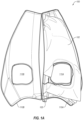
- FIG. 1A depicts an airbag module 100 comprising an airbag cushion 102 positioned within an airbag cover 110 configured to be positioned within or otherwise coupled to a vehicle seat according to some embodiments.
- Airbag cover 110 is defined by first and second airbag cover pieces 110A and 110B, respectively, that are configured to be opened and closed similar to a clamshell with an open side and a closed side or spine having one or more hinged and/or pivotable portions.
- each of cover pieces 110A and 110B comprises a respective opening 115A/115B, respectively, through which a structural element of the seat may extend, as discussed in greater detail below.
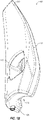
- a portion of an armrest assembly may extend through openings 115A/115B, which, as shown in FIG. 1B , combine to define a single opening 115.
- an inflator 105 may be positioned within an inner chamber of cover 110 defined by pieces 110A and 110B.
- inflator 105 is positioned along the spine region of the cover 110, which may be the pivoting portion of the cover 110 and therefore expected to be relatively stable during deployment.
- Airbag cushion 102 may be wrapped about one or both of openings 115A/115B, as shown in FIG. 1A .
- cushion 102 there may be a negative portion of cushion 102 formed by sewing a portion of the cushion 102 that extends about, or at least substantially about, a perimeter of opening 115, or the cushion 102 may be simply folded or otherwise positioned within cover 110 such that it extends about, or at least substantially about, the perimeter of opening 115.
- a portion of inflator 105 may extend from an opening formed in cover 110 to allow for providing a suitable electrical connection, if desired.
- cover 110 may be defined by a relatively rigid and/or strong material, such as a rigid thermoplastic material, positioning a portion of inflator through the aforementioned opening may further provide stability to the assembly during deployment.
- inflator 105 is preferably positioned in the seat 10 at a location adjacent to and/or at least substantially behind a projecting portion of an armrest assembly or another protruding structural element.
- cushion 102 be coupled to both inflator 105 and to one or more portions of cover 110.
- the inflator 105 itself may serve as one coupling location, in which case the cushion 102 may, in some embodiments, only be coupled directly to an upper portion of cover 110. This may allow deployment forces to be applied initially to the inflator 105 and then from the inflator to a portion of an armrest assembly or another seat structural element, as discussed below.
- a leading edge of cover 110 may comprise a slit 112 that, as discussed below, may be configured to pivot open sufficiently to allow the inflating airbag cushion 102 therein to deploy adjacent to a vehicle occupant.
- some embodiments may comprise one or more shaped features, such as groove 114, to accommodate portions of a vehicle seat.
- groove 114 may be configured to receive a portion of a vehicle seat so that cover 110 can extend about both opposing sides of the vehicle seat and accommodate a suitable portion of the vehicle seat therewithin.
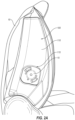
- FIG. 2A and 2B depict a vehicle seat 10 with airbag module 100 positioned therein. More particularly, FIG. 2A depicts cover 110 positioned within a seatback portion of vehicle seat 10 along one side thereof. It should be understood, however, that cover 110 may be positioned along either side, or both sides, of vehicle seat 10, or may be positioned in another portion of the vehicle seat 10, such as the base portion of the seat 10, in contemplated alternative embodiments. It should also be understood that cover 110 may be positioned within a seatback comprising foam encapsulated in a seat cover, or may be positioned in other seatbacks of vehicle seats, such as seats of autonomous vehicles, which may lack these features.
- an armrest mount 15 extends through opening 115, which, again, may be defined by two separate openings formed in pivotable pieces together defining airbag cover 110 in some preferred embodiments.
- armrest mount 15, or another structural element of seat 10 extends through opening 115 so as to engage a portion of cover 110 defining opening 115 about an entire perimeter of opening 115, or at least about opposing sides of cover 110 defining opening 115, with relatively little tolerance.
- the armrest mount 15, or another structural element of seat 10 have a shape and size that is at least substantially identical (slightly smaller, of course, to allow for this element to extend through opening 115) to the size and shape of opening 115.
- opening 115 need not be an opening having a full perimeter, as shown in the figures.
- This may provide a number of benefits. For example, this may allow cover 110 to be positioned within seat 10 without the need for typical bolts or other rigid fasteners because the deployment forces may be transferred from the armrest mount 15 or another structural element to the seat frame.
- some embodiments may use simple clips (not shown) to secure the module 100 to the seat 10.
- fasteners may be used as well, or alternatively.
- some embodiments may comprise typical inflator studs or other fasteners, but in some cases without use of additional fasteners that specifically extend from and/or are directly coupled to the housing 110 itself.
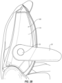
- FIG. 2B illustrates module 100 with armrest 20 coupled to armrest mount 25 in an extended configuration.
- module 100 is preferably configured to deploy adjacent one or both sides of a vehicle seat with an armrest 20 or, in other embodiments, another structural element, extending through at least a portion of the housing 110 in any configuration, such as, for the depicted embodiment, in either a retracted configuration or the extended configuration shown in FIG. 2B .
- the housing 110 may also be configured to replace or otherwise provide support to the seat 10, such as providing or supporting a bolster space to the seat 10.
- FIG. 3A illustrates the airbag module 100 following deployment.
- airbag cushion 102 is shown extending and being deployed from a front leading edge of housing 110 (again, through slit/opening 112 shown in FIG. 1B ).
- the force of the inflating airbag cushion 102 against the inner walls of the housing 110 may result in section 110A pivoting open with respect to portion 110B sufficiently to allow the inflating cushion 102 to exit housing 110.
- cushion 102 may be configured to deploy adjacent to armrest 20 in the depicted, extended configuration without the armrest interfering with desired deployment characteristics.
- FIG. 3B depicts deployment of airbag cushion 102 with armrest 20 in its retracted configuration in which armrest 20 is rotated up against seat 10.
- module 100 is configured to facilitate deployment of airbag cushion 102 in either configuration.
- FIG. 4A depicts an alternative embodiment of an airbag module 200 comprising a housing 210 with an opening 215 through which a tray table mount 25 extends.
- a tray table arm 20 is coupled with a table 22, which may retractably positionable adjacent to a vehicle occupant 30.
- Module 200 may therefore be particularly useful for, for example, autonomous vehicles.
- Housing 210 may therefore comprise, in some embodiments, a rigid, decorative cover that may be configured to both protect the airbag cushion or cushions therein (see cushions 202A and 202B in FIG. 4B ) and may be mounted to or within the seat 10 with or without seat foam or a seat cover extending over the housing 210.
- module 200 comprises a first or outer cushion chamber 202A and a second or inner cushion chamber 202B.
- Chambers 202A and 202B may be fluidly coupled such that a single inflator (not shown) may be used to inflate both cushions/chambers 202A/202B.
- Chamber 202B may be configured to provide specific protection primarily to the head of occupant 30, whereas chamber 202A may be configured to provide protection to the body of occupant 30 and/or to provide a foundation for stabilizing chamber 202B.
- a portion of chamber 202A or, a single cushion in alternative embodiments having only one may be configured to deploy partially within a space in between arm 20 and table 22.
- the cushion(s) may simply be configured to deploy inside of arms 20 and table 22 such that these structural elements do not impede the ability of the cushion(s) to deploy.
- module 200 is configured to transfer forces from deployment of the airbag cushion(s) to at least a portion of the tray table assembly and/or the frame of seat 10 during deployment.
- airbag cover 210 is configured to be coupled to the vehicle seat 10 without use of bolts or screws coupled directly to cover 210 or, in some such embodiments, without the use of bolts or screws altogether.
- cushions may be deployable from both sides of a vehicle seat 10.
- a pair of cushions 202C and 202D is positioned on the opposite side of seat 10 relative to cushions 202A and 202B.
- cushions 202C and 202D may be deployable from a separate cover that may be positioned within or otherwise coupled to their respective side of seat 10.
- this separate cover may, like cover 210, comprise an opening, either full or partial, through which a structural element of seat 10, such as arms 20A and/or 20B, may extend.
- a structural element of seat 10 such as arms 20A and/or 20B
- Other examples of seat structural elements that may extend through housings/covers of contemplated alternative embodiments and be used to transfer airbag deployment forces therethrough to the frame of the seat and/or vehicle include footrests, leg recliners, seat mount bars, a seat belt or a structural element of a seat belt assembly, and the like.
Landscapes
- Engineering & Computer Science (AREA)
- Mechanical Engineering (AREA)
- Transportation (AREA)
- Aviation & Aerospace Engineering (AREA)
- Physics & Mathematics (AREA)
- Fluid Mechanics (AREA)
- Seats For Vehicles (AREA)
- Air Bags (AREA)
Abstract
Description
- Although airbag cushions have been proposed that deploy from a vehicle seat, a variety of problems face such current solutions. For example, it may be difficult to find sufficient space within a vehicle seat for the airbag cover. In addition, deployment may result in forces being applied to portions of the seat that may require the module to be mounted to the seat using studs/bolts, or screws. Moreover, various features of a typical vehicle seat, such as armrests, may interfere with desired deployment kinematics, particularly features that are reconfigurable and may therefore present differing contact surfaces for a deploying airbag cushion.
- The present inventors have therefore determined that it would be desirable to provide apparatus, systems and methods that overcome one or more of the foregoing limitations and/or other limitations of the prior art. In some embodiments, the inventive concepts disclosed herein may therefore provide an airbag module having a cover that receives a vehicle seat structural element therethrough and/or otherwise provides one or more points of contact to transfer deployment forces through the structural element into a larger portion of the seat itself, such as the seat frame.
- In a more particular example of a seat-mounted airbag module according to some embodiments, the module may comprise an airbag cover configured to be positioned within a seat, of a vehicle, such as within a seat back of a vehicle seat, for example; an inflator positioned within the airbag cover; and an airbag cushion positioned within the airbag cover and configured to deploy from one lateral side of the seat back adjacent to a protruding structural element of the vehicle seat, such as an armrest mount or another portion of an armrest assembly of the vehicle seat. The airbag module may be configured to transfer forces from deployment of the airbag cushion to at least a portion of the armrest assembly or another protruding structural element during deployment. In some embodiment, these forces may be transferred via the structural element to the vehicle seat frame. Preferably the inflator is positioned behind the protruding structural element.
- In some embodiments, the airbag cover may comprise an opening configured to receive a portion of the armrest or other structural element therethrough. In some such embodiments, the opening may be configured to receive an armrest mount of the armrest therethrough.
- In some embodiments, the airbag cover may be configured to be coupled to the vehicle seat without use of bolts or screws.
- In some embodiments, the airbag cover may comprise a clamshell cover, which may comprise a spine; a first cover piece pivotably coupled to the spine; and a second cover piece pivotably coupled to the spine. In some such embodiments, the inflator may be positioned along the spine.
- In another example of an airbag module according to some embodiments, the module may comprise an airbag cover configured to be positioned within a vehicle seat. The airbag cover may comprise an opening that may be configured to receive a structural element of the vehicle seat therethrough. The module may further comprise an airbag cushion positioned within the airbag cover and configured to deploy from the airbag cover such that forces from deployment of the airbag cushion are directed applied to the structural element and/or to a frame of the vehicle seat.
- In some embodiments, the structural element may comprise a portion of an armrest assembly, such as an armrest mount.
- Some embodiments may further comprise an inflator. In some such embodiments, the airbag cushion may be separately coupled to the inflator on opposing sides of the inflator, such as extending about, or at least substantially about, a perimeter of the opening.
- In some embodiments, the airbag cushion may be positioned within the airbag cover such that at least a portion of the airbag cushion extends about a periphery of the opening from a first side of the inflator to a second side of the inflator opposite the first side.
- In some embodiments, the airbag cover may comprise a clamshell cover comprising: a spine, a first cover piece pivotably coupled to the spine, and a second cover piece pivotably coupled to the spine. In some such embodiments, the airbag cushion may be configured to deploy from along an edge of the airbag cover positioned opposite from the spine.
- In an example of a vehicle seat according to some embodiments, the vehicle seat may comprise a seat base and a seat back extending from the seat base. The vehicle seat may further comprise a structural assembly comprising a protruding member extending from at least a portion of the vehicle seat. An airbag module may be positioned within the vehicle seat, which airbag module may comprise an airbag cover comprising an opening. The protruding member may extend through the opening. In some embodiments, the protruding member may be fully surrounded by the opening. An airbag cushion may be positioned within the airbag cover and may be configured to deploy from the airbag cover along one side of the vehicle seat.
- In some embodiments, the protruding member may comprise an armrest. In some such embodiments, the armrest may be adjustable between upright and extended positions. Thus, preferably, the airbag cushion is configured to deploy adjacent to the armrest in either the upright or extended positions. In some embodiments, the airbag cushion may be configured to deploy adjacent to an inner surface of the armrest in the extended position.
- In some embodiments, the airbag module may be positioned and configured to transfer forces from deployment of the airbag cushion to the protruding member during deployment. In some such embodiments, the airbag module may be positioned and configured to transfer reaction forces from an occupant contacting the airbag cushion during deployment to the protruding member and from the protruding member to a frame of the vehicle seat during deployment.
- In some embodiments, the airbag module may be positioned within the seat back.
- In some embodiments, the airbag cover may be coupled to the seat back without use of bolts or screws. In some such embodiments, the airbag module may further comprise an inflator configured to inflate the airbag cushion. In some such embodiments, the inflator may be coupled to the seat back using one or more inflator studs.
- The features, structures, steps, or characteristics disclosed herein in connection with one embodiment may be combined in any suitable manner in one or more alternative embodiments.
- Non-limiting and non-exhaustive embodiments of the disclosure are described, including various embodiments of the disclosure with reference to the figures, in which:
-
FIG. 1A depicts an example of a seat-mounted airbag module in an open configuration according to some embodiments; -
FIG. 1B is a perspective view of the seat-mounted airbag module ofFIG. 1A in a closed configuration; -
FIG. 2A depicts a seat having an armrest mount extending through an opening of an airbag module according to some embodiments; -
FIG. 2B depicts the airbag module ofFIG. 2A with an armrest extending from the armrest mount; -
FIG. 3A depicts a seat-mounted and armrest coupled airbag module during deployment with the armrest in an extended configuration; -
FIG. 3B depicts the seat-mounted and armrest coupled airbag module ofFIG. 3A during deployment with the armrest in a retracted configuration; -
FIG. 4A depicts an alternative embodiment configured to deploy adjacent to a seat-mounted tray table; -
FIG. 4B is a front view depicting the embodiment ofFIG. 4A during deployment; and -
FIG. 4C is a front view depicting an alternative embodiment comprising cushions deployable from both sides of a vehicle seat during deployment. - A detailed description of apparatus, systems, and methods consistent with various embodiments of the present disclosure is provided below. While several embodiments are described, it should be understood that the disclosure is not limited to any of the specific embodiments disclosed, but instead encompasses numerous alternatives, modifications, and equivalents. In addition, while numerous specific details are set forth in the following description in order to provide a thorough understanding of the embodiments disclosed herein, some embodiments can be practiced without some or all of these details. Moreover, for the purpose of clarity, certain technical material that is known in the related art has not been described in detail in order to avoid unnecessarily obscuring the disclosure.
- As used herein, the term "substantially" refers to the complete or nearly complete extent or degree of an action, characteristic, property, state, structure, item, or result to function as indicated. For example, an object that is "substantially" cylindrical or "substantially" perpendicular would mean that the object/feature is either cylindrical/perpendicular or nearly cylindrical/perpendicular so as to result in the same or nearly the same function. The exact allowable degree of deviation provided by this term may depend on the specific context. The use of "substantially" is equally applicable when used in a negative connotation to refer to the complete or near complete lack of an action, characteristic, property, state, structure, item, or result. For example, structure which is "substantially free of" a bottom would either completely lack a bottom or so nearly completely lack a bottom that the effect would be effectively the same as if it completely lacked a bottom.
- Similarly, as used herein, the term "about" is used to provide flexibility to a numerical range endpoint by providing that a given value may be "a little above" or "a little below" the endpoint while still accomplishing the function associated with the range.
- The embodiments of the disclosure may be best understood by reference to the drawings, wherein like parts may be designated by like numerals. It will be readily understood that the components of the disclosed embodiments, as generally described and illustrated in the figures herein, could be arranged and designed in a wide variety of different configurations. Thus, the following detailed description of the embodiments of the apparatus and methods of the disclosure is not intended to limit the scope of the disclosure, as claimed, but is merely representative of possible embodiments of the disclosure. In addition, the steps of a method do not necessarily need to be executed in any specific order, or even sequentially, nor need the steps be executed only once, unless otherwise specified. Additional details regarding certain preferred embodiments and implementations will now be described in greater detail with reference to the accompanying drawings.
-
FIG. 1A depicts anairbag module 100 comprising anairbag cushion 102 positioned within anairbag cover 110 configured to be positioned within or otherwise coupled to a vehicle seat according to some embodiments.Airbag cover 110 is defined by first and secondairbag cover pieces - As shown in
FIG. 1A , each ofcover pieces respective opening 115A/115B, respectively, through which a structural element of the seat may extend, as discussed in greater detail below. In preferred embodiments, for example, a portion of an armrest assembly may extend throughopenings 115A/115B, which, as shown inFIG. 1B , combine to define asingle opening 115. - As shown in both
FIGS. 1A and1B , aninflator 105 may be positioned within an inner chamber ofcover 110 defined bypieces inflator 105 is positioned along the spine region of thecover 110, which may be the pivoting portion of thecover 110 and therefore expected to be relatively stable during deployment.Airbag cushion 102 may be wrapped about one or both ofopenings 115A/115B, as shown inFIG. 1A . Thus, there may be a negative portion ofcushion 102 formed by sewing a portion of thecushion 102 that extends about, or at least substantially about, a perimeter ofopening 115, or thecushion 102 may be simply folded or otherwise positioned withincover 110 such that it extends about, or at least substantially about, the perimeter ofopening 115. - As also shown in both
FIGS. 1A and1B , a portion ofinflator 105 may extend from an opening formed incover 110 to allow for providing a suitable electrical connection, if desired. Because in preferred embodiments cover 110 may be defined by a relatively rigid and/or strong material, such as a rigid thermoplastic material, positioning a portion of inflator through the aforementioned opening may further provide stability to the assembly during deployment. - As shown in the drawings,
inflator 105 is preferably positioned in theseat 10 at a location adjacent to and/or at least substantially behind a projecting portion of an armrest assembly or another protruding structural element. - It may also be desired that
cushion 102 be coupled to bothinflator 105 and to one or more portions ofcover 110. For example, in preferred embodiments, there may be clips, fasteners, or other coupling means formed along both an upper and lower portion ofcover 110 to whichcushion 102 may be coupled. In some embodiments, however, the inflator 105 itself may serve as one coupling location, in which case thecushion 102 may, in some embodiments, only be coupled directly to an upper portion ofcover 110. This may allow deployment forces to be applied initially to theinflator 105 and then from the inflator to a portion of an armrest assembly or another seat structural element, as discussed below. - As shown in
FIG. 1B , a leading edge ofcover 110 may comprise aslit 112 that, as discussed below, may be configured to pivot open sufficiently to allow the inflatingairbag cushion 102 therein to deploy adjacent to a vehicle occupant. As also shown inFIG. 1B , some embodiments may comprise one or more shaped features, such asgroove 114, to accommodate portions of a vehicle seat. In the depicted embodiment, as will be more readily apparent in connection with later figures, groove 114 may be configured to receive a portion of a vehicle seat so thatcover 110 can extend about both opposing sides of the vehicle seat and accommodate a suitable portion of the vehicle seat therewithin. -
FIG. 2A and2B depict avehicle seat 10 withairbag module 100 positioned therein. More particularly,FIG. 2A depictscover 110 positioned within a seatback portion ofvehicle seat 10 along one side thereof. It should be understood, however, thatcover 110 may be positioned along either side, or both sides, ofvehicle seat 10, or may be positioned in another portion of thevehicle seat 10, such as the base portion of theseat 10, in contemplated alternative embodiments. It should also be understood thatcover 110 may be positioned within a seatback comprising foam encapsulated in a seat cover, or may be positioned in other seatbacks of vehicle seats, such as seats of autonomous vehicles, which may lack these features. - As shown in
FIG. 2A , anarmrest mount 15 extends throughopening 115, which, again, may be defined by two separate openings formed in pivotable pieces together definingairbag cover 110 in some preferred embodiments. Preferably,armrest mount 15, or another structural element ofseat 10, extends throughopening 115 so as to engage a portion ofcover 110 definingopening 115 about an entire perimeter ofopening 115, or at least about opposing sides ofcover 110 definingopening 115, with relatively little tolerance. In other words, it may be preferred for certain applications that thearmrest mount 15, or another structural element ofseat 10, have a shape and size that is at least substantially identical (slightly smaller, of course, to allow for this element to extend through opening 115) to the size and shape ofopening 115. - In this manner, deployment forces may be transferred to
armrest mount 15 or whichever alternative structural element is extending throughopening 115 or otherwise extends adjacent to cover 110 (in some embodiments, for example, opening 115 need not be an opening having a full perimeter, as shown in the figures). This may provide a number of benefits. For example, this may allowcover 110 to be positioned withinseat 10 without the need for typical bolts or other rigid fasteners because the deployment forces may be transferred from thearmrest mount 15 or another structural element to the seat frame. Thus, some embodiments may use simple clips (not shown) to secure themodule 100 to theseat 10. Of course, in some embodiments, fasteners may be used as well, or alternatively. For example, some embodiments may comprise typical inflator studs or other fasteners, but in some cases without use of additional fasteners that specifically extend from and/or are directly coupled to thehousing 110 itself. -
FIG. 2B illustratesmodule 100 witharmrest 20 coupled toarmrest mount 25 in an extended configuration. As shown in later figures,module 100 is preferably configured to deploy adjacent one or both sides of a vehicle seat with an armrest 20 or, in other embodiments, another structural element, extending through at least a portion of thehousing 110 in any configuration, such as, for the depicted embodiment, in either a retracted configuration or the extended configuration shown inFIG. 2B . In some embodiments, thehousing 110 may also be configured to replace or otherwise provide support to theseat 10, such as providing or supporting a bolster space to theseat 10. -
FIG. 3A illustrates theairbag module 100 following deployment. Thus,airbag cushion 102 is shown extending and being deployed from a front leading edge of housing 110 (again, through slit/opening 112 shown inFIG. 1B ). Given the clamshell configuration previously mentioned and best seen inFIGS. 1A and1B , the force of the inflatingairbag cushion 102 against the inner walls of thehousing 110 may result insection 110A pivoting open with respect toportion 110B sufficiently to allow the inflatingcushion 102 to exithousing 110. As also shown inFIG. 3A , cushion 102 may be configured to deploy adjacent to armrest 20 in the depicted, extended configuration without the armrest interfering with desired deployment characteristics. -
FIG. 3B depicts deployment ofairbag cushion 102 witharmrest 20 in its retracted configuration in which armrest 20 is rotated up againstseat 10. Again,module 100 is configured to facilitate deployment ofairbag cushion 102 in either configuration. -
FIG. 4A depicts an alternative embodiment of anairbag module 200 comprising ahousing 210 with anopening 215 through which atray table mount 25 extends. Atray table arm 20 is coupled with a table 22, which may retractably positionable adjacent to avehicle occupant 30.Module 200 may therefore be particularly useful for, for example, autonomous vehicles.Housing 210 may therefore comprise, in some embodiments, a rigid, decorative cover that may be configured to both protect the airbag cushion or cushions therein (seecushions FIG. 4B ) and may be mounted to or within theseat 10 with or without seat foam or a seat cover extending over thehousing 210. - As shown in
FIG. 4B , in some embodiments, multiple cushions and/or cushion chambers may be provided. Thus,module 200 comprises a first orouter cushion chamber 202A and a second orinner cushion chamber 202B.Chambers chambers 202A/202B.Chamber 202B may be configured to provide specific protection primarily to the head ofoccupant 30, whereaschamber 202A may be configured to provide protection to the body ofoccupant 30 and/or to provide a foundation for stabilizingchamber 202B. - As also shown in
FIG. 4B , a portion ofchamber 202A or, a single cushion in alternative embodiments having only one, may be configured to deploy partially within a space in betweenarm 20 and table 22. Alternatively, however, the cushion(s) may simply be configured to deploy inside ofarms 20 and table 22 such that these structural elements do not impede the ability of the cushion(s) to deploy. In addition, as previously discussed, preferablymodule 200 is configured to transfer forces from deployment of the airbag cushion(s) to at least a portion of the tray table assembly and/or the frame ofseat 10 during deployment. Further, in some embodiments,airbag cover 210 is configured to be coupled to thevehicle seat 10 without use of bolts or screws coupled directly to cover 210 or, in some such embodiments, without the use of bolts or screws altogether. - As shown in
FIG. 4C , in some embodiments, cushions may be deployable from both sides of avehicle seat 10. Thus, in the depicted embodiment, a pair ofcushions seat 10 relative tocushions cushions seat 10. - In addition, in preferred embodiments, this separate cover may, like
cover 210, comprise an opening, either full or partial, through which a structural element ofseat 10, such asarms 20A and/or 20B, may extend. Other examples of seat structural elements that may extend through housings/covers of contemplated alternative embodiments and be used to transfer airbag deployment forces therethrough to the frame of the seat and/or vehicle include footrests, leg recliners, seat mount bars, a seat belt or a structural element of a seat belt assembly, and the like. - The foregoing specification has been described with reference to various embodiments and implementations. However, one of ordinary skill in the art will appreciate that various modifications and changes can be made without departing from the scope of the present disclosure. For example, various operational steps, as well as components for carrying out operational steps, may be implemented in various ways depending upon the particular application or in consideration of any number of cost functions associated with the operation of the system. Accordingly, any one or more of the steps may be deleted, modified, or combined with other steps. Further, this disclosure is to be regarded in an illustrative rather than a restrictive sense, and all such modifications are intended to be included within the scope thereof. Likewise, benefits, other advantages, and solutions to problems have been described above with regard to various embodiments. However, benefits, advantages, solutions to problems, and any element(s) that may cause any benefit, advantage, or solution to occur or become more pronounced, are not to be construed as a critical, a required, or an essential feature or element.
- Those having skill in the art will appreciate that many changes may be made to the details of the above-described embodiments without departing from the underlying principles of the invention. The scope of the present invention should, therefore, be determined only by the following claims.
Claims (9)
- A seat-mounted airbag module [100] comprising an airbag cover [110] configured to be positioned within a seat back of a vehicle seat [10] and an inflator [105] positioned within the airbag cover [110] and an airbag cushion [102] positioned within the airbag cover [110], characterized in that the airbag cushion [102] is configured to deploy from one lateral side of the seat back adjacent to an armrest [20] of the vehicle seat [10], wherein the airbag module [100] is configured to transfer forces from deployment of the airbag cushion [102] to at least a portion o an armrest assembly comprising the armrest [20] during deployment.
- The seat-mounted airbag module [100] of claim 1, wherein the airbag cover [110] comprises an opening [115] configured to receive a portion of the armrest [20] therethrough.
- The seat-mounted airbag module [100] of claim 2, wherein the opening [115] is configured to receive an armrest mount [25] of the armrest [20] therethrough.
- The seat-mounted airbag module [100] of any of claims 1-3, wherein the airbag cover [110] is configured to be coupled to the vehicle seat [10] without use of bolts or screws.
- The seat-mounted airbag module [100] of any of claims 1-4, wherein the airbag cover [110] comprises a clamshell cover comprising:a spine;a first cover piece [110A] pivotably coupled to the spine; anda second cover [110B] piece pivotably coupled to the spine.
- The seat-mounted airbag module [100] of claim 5, wherein the inflator [105] is positioned along the spine.
- The seat-mounted airbag module [100] of any of claims 1 and 4-6, wherein the airbag cover [110] comprises an opening [115], and wherein the airbag cushion [102] is positioned within the airbag cover [110] such that at least a portion of the airbag cushion [102] extends about a periphery of the opening [115] from a first side of the inflator [105] to a second side of the inflator [105] opposite the first side.
- The seat-mounted airbag module [100] of any of claims 1-7, wherein the armrest [20] is adjustable between upright and extended positions, wherein the airbag cushion [102] is configured to deploy adjacent to the armrest [20] in either the upright or extended positions, and wherein the airbag cushion [102] is configured to deploy adjacent to an inner surface of the armrest [20] in the extended position.
- The seat-mounted airbag module [100] of any of claims 1-8, wherein the airbag module [100] is positioned and configured to transfer reaction forces from an occupant contacting the airbag cushion [102] during deployment to the armrest [20] and from the armrest [20] to a frame of the vehicle seat [10] during deployment.
Applications Claiming Priority (1)
| Application Number | Priority Date | Filing Date | Title |
|---|---|---|---|
| US17/412,010 US11608020B1 (en) | 2021-08-25 | 2021-08-25 | Vehicle seat armrest coupled airbag modules |
Publications (2)
| Publication Number | Publication Date |
|---|---|
| EP4140828A1 true EP4140828A1 (en) | 2023-03-01 |
| EP4140828B1 EP4140828B1 (en) | 2025-10-01 |
Family
ID=82932540
Family Applications (1)
| Application Number | Title | Priority Date | Filing Date |
|---|---|---|---|
| EP22190319.8A Active EP4140828B1 (en) | 2021-08-25 | 2022-08-12 | Vehicle seat armrest coupled airbag modules |
Country Status (5)
| Country | Link |
|---|---|
| US (1) | US11608020B1 (en) |
| EP (1) | EP4140828B1 (en) |
| JP (1) | JP7445716B2 (en) |
| KR (1) | KR102742425B1 (en) |
| CN (1) | CN115723700B (en) |
Families Citing this family (4)
| Publication number | Priority date | Publication date | Assignee | Title |
|---|---|---|---|---|
| USD1020601S1 (en) * | 2020-11-30 | 2024-04-02 | Zoox, Inc. | Vehicle airbag system |
| US12441266B2 (en) * | 2023-04-26 | 2025-10-14 | Ford Global Technologies, Llc | Airbag assembly for child-restraint system |
| US12208763B1 (en) * | 2023-07-27 | 2025-01-28 | Ford Global Technologies, Llc | Armrest mounted dual chamber airbag |
| USD1113634S1 (en) * | 2024-02-07 | 2026-02-17 | Hyundai Motor Company | Inflatable head and neck protection device |
Citations (2)
| Publication number | Priority date | Publication date | Assignee | Title |
|---|---|---|---|---|
| JP2018199409A (en) * | 2017-05-26 | 2018-12-20 | トヨタ紡織株式会社 | Vehicle seat |
| DE102020101621A1 (en) * | 2020-01-23 | 2021-07-29 | Autoliv Development Ab | AIRBAG DEVICE OF A VEHICLE |
Family Cites Families (16)
| Publication number | Priority date | Publication date | Assignee | Title |
|---|---|---|---|---|
| US5492361A (en) * | 1995-01-26 | 1996-02-20 | Kim; Ki I. | Side airbag apparatus |
| JP3028498U (en) * | 1995-03-23 | 1996-09-03 | モートン インターナショナル,インコーポレイティド | Vehicles with side impact airbags and armrests for their seats |
| KR970010318A (en) * | 1995-08-18 | 1997-03-27 | 배순훈 | Driver's armrest for car to alleviate side impact |
| JP4083916B2 (en) * | 1999-03-29 | 2008-04-30 | 日本プラスト株式会社 | Side airbag device |
| JP5333728B2 (en) * | 2008-11-06 | 2013-11-06 | マツダ株式会社 | Side structure of front seat for vehicle |
| US8924086B2 (en) * | 2012-02-01 | 2014-12-30 | GM Global Technology Operations LLC | Method for control of seat mounted airbag in a seat with armrest |
| JP6217548B2 (en) * | 2014-07-11 | 2017-10-25 | トヨタ紡織株式会社 | Vehicle seat |
| JP6447432B2 (en) * | 2015-09-11 | 2019-01-09 | トヨタ自動車株式会社 | Far-side airbag device and vehicle seat |
| WO2017068941A1 (en) | 2015-10-23 | 2017-04-27 | オートリブ ディベロップメント エービー | Side airbag device |
| JP2018172004A (en) * | 2017-03-31 | 2018-11-08 | 株式会社Subaru | Armrest |
| JP6537120B2 (en) * | 2017-03-31 | 2019-07-03 | 株式会社Subaru | Armrest |
| US10343644B2 (en) * | 2017-10-09 | 2019-07-09 | Ford Global Technologies, Llc | Seat with restraint system |
| DE102017010794A1 (en) * | 2017-11-22 | 2018-07-19 | Daimler Ag | vehicle seat |
| KR102647195B1 (en) * | 2018-12-12 | 2024-03-12 | 현대자동차주식회사 | Safety device for vehicle |
| FR3102961A1 (en) * | 2019-11-13 | 2021-05-14 | Psa Automobiles Sa | Armrest module for bench backrest incorporating an airbag |
| US11273783B1 (en) * | 2020-09-14 | 2022-03-15 | Ford Global Technologies, Llc | Side airbag assembly |
-
2021
- 2021-08-25 US US17/412,010 patent/US11608020B1/en active Active
-
2022
- 2022-08-10 CN CN202210957561.5A patent/CN115723700B/en active Active
- 2022-08-12 EP EP22190319.8A patent/EP4140828B1/en active Active
- 2022-08-17 JP JP2022129784A patent/JP7445716B2/en active Active
- 2022-08-22 KR KR1020220105078A patent/KR102742425B1/en active Active
Patent Citations (2)
| Publication number | Priority date | Publication date | Assignee | Title |
|---|---|---|---|---|
| JP2018199409A (en) * | 2017-05-26 | 2018-12-20 | トヨタ紡織株式会社 | Vehicle seat |
| DE102020101621A1 (en) * | 2020-01-23 | 2021-07-29 | Autoliv Development Ab | AIRBAG DEVICE OF A VEHICLE |
Also Published As
| Publication number | Publication date |
|---|---|
| CN115723700B (en) | 2025-11-11 |
| US11608020B1 (en) | 2023-03-21 |
| CN115723700A (en) | 2023-03-03 |
| JP7445716B2 (en) | 2024-03-07 |
| EP4140828B1 (en) | 2025-10-01 |
| US20230062306A1 (en) | 2023-03-02 |
| KR20230030540A (en) | 2023-03-06 |
| KR102742425B1 (en) | 2024-12-17 |
| JP2023033171A (en) | 2023-03-09 |
Similar Documents
| Publication | Publication Date | Title |
|---|---|---|
| EP4140828B1 (en) | Vehicle seat armrest coupled airbag modules | |
| US7441797B2 (en) | Vehicle seat assembly | |
| CN1189344C (en) | Child seat device | |
| US8905431B1 (en) | Side airbag assembly for a vehicle seat | |
| US7594675B2 (en) | Airbag system | |
| US11958428B2 (en) | Airbag device and vehicle seat | |
| CN111252028B (en) | Seat assembly comprising an air bag integrated into a tulip armchair | |
| EP3863889B1 (en) | Vehicle seating | |
| BR102016004619A2 (en) | vehicle seat mounting with a side impact airbag deployment mechanism | |
| BR102017020865B1 (en) | VEHICLE SEAT WITH SIDE AIRBAG DEVICE | |
| US5845966A (en) | Vehicle side impact air bag assembly | |
| WO2020080050A1 (en) | Vehicle occupant rerstraining device | |
| JPH07228213A (en) | Airbag device | |
| JP3102238B2 (en) | Airbag device for passenger seat | |
| US20160009239A1 (en) | Side airbag module and assembly | |
| CN117957148A (en) | Vehicle seat provided with installed safety system | |
| JP2007126117A (en) | Vehicle seat | |
| CN107804267B (en) | Seat back with side airbag energy management system | |
| CN220220578U (en) | Storage device for vehicle and vehicle | |
| MX2014003929A (en) | Self-adjusting head restraint. | |
| JPH1159312A (en) | Occupant protection device | |
| JP2021120261A (en) | Seat belt attachment structure | |
| JP2007083997A (en) | Crew restraint system | |
| JP2024084073A (en) | Vehicle seat | |
| JP2024061403A (en) | Vehicle seat |
Legal Events
| Date | Code | Title | Description |
|---|---|---|---|
| PUAI | Public reference made under article 153(3) epc to a published international application that has entered the european phase |
Free format text: ORIGINAL CODE: 0009012 |
|
| STAA | Information on the status of an ep patent application or granted ep patent |
Free format text: STATUS: REQUEST FOR EXAMINATION WAS MADE |
|
| 17P | Request for examination filed |
Effective date: 20220812 |
|
| AK | Designated contracting states |
Kind code of ref document: A1 Designated state(s): AL AT BE BG CH CY CZ DE DK EE ES FI FR GB GR HR HU IE IS IT LI LT LU LV MC MK MT NL NO PL PT RO RS SE SI SK SM TR |
|
| STAA | Information on the status of an ep patent application or granted ep patent |
Free format text: STATUS: EXAMINATION IS IN PROGRESS |
|
| 17Q | First examination report despatched |
Effective date: 20240422 |
|
| GRAP | Despatch of communication of intention to grant a patent |
Free format text: ORIGINAL CODE: EPIDOSNIGR1 |
|
| STAA | Information on the status of an ep patent application or granted ep patent |
Free format text: STATUS: GRANT OF PATENT IS INTENDED |
|
| INTG | Intention to grant announced |
Effective date: 20250313 |
|
| GRAS | Grant fee paid |
Free format text: ORIGINAL CODE: EPIDOSNIGR3 |
|
| GRAA | (expected) grant |
Free format text: ORIGINAL CODE: 0009210 |
|
| STAA | Information on the status of an ep patent application or granted ep patent |
Free format text: STATUS: THE PATENT HAS BEEN GRANTED |
|
| AK | Designated contracting states |
Kind code of ref document: B1 Designated state(s): AL AT BE BG CH CY CZ DE DK EE ES FI FR GB GR HR HU IE IS IT LI LT LU LV MC MK MT NL NO PL PT RO RS SE SI SK SM TR |
|
| REG | Reference to a national code |
Ref country code: GB Ref legal event code: FG4D Ref country code: CH Ref legal event code: F10 Free format text: ST27 STATUS EVENT CODE: U-0-0-F10-F00 (AS PROVIDED BY THE NATIONAL OFFICE) Effective date: 20251001 |
|
| REG | Reference to a national code |
Ref country code: DE Ref legal event code: R096 Ref document number: 602022022171 Country of ref document: DE |
|
| REG | Reference to a national code |
Ref country code: IE Ref legal event code: FG4D |
|
| REG | Reference to a national code |
Ref country code: NL Ref legal event code: MP Effective date: 20251001 |
|
| REG | Reference to a national code |
Ref country code: AT Ref legal event code: MK05 Ref document number: 1842228 Country of ref document: AT Kind code of ref document: T Effective date: 20251001 |
|
| PG25 | Lapsed in a contracting state [announced via postgrant information from national office to epo] |
Ref country code: NL Free format text: LAPSE BECAUSE OF FAILURE TO SUBMIT A TRANSLATION OF THE DESCRIPTION OR TO PAY THE FEE WITHIN THE PRESCRIBED TIME-LIMIT Effective date: 20251001 |
|
| PG25 | Lapsed in a contracting state [announced via postgrant information from national office to epo] |
Ref country code: ES Free format text: LAPSE BECAUSE OF FAILURE TO SUBMIT A TRANSLATION OF THE DESCRIPTION OR TO PAY THE FEE WITHIN THE PRESCRIBED TIME-LIMIT Effective date: 20251001 |
|
| REG | Reference to a national code |
Ref country code: LT Ref legal event code: MG9D |
|
| PG25 | Lapsed in a contracting state [announced via postgrant information from national office to epo] |
Ref country code: NO Free format text: LAPSE BECAUSE OF FAILURE TO SUBMIT A TRANSLATION OF THE DESCRIPTION OR TO PAY THE FEE WITHIN THE PRESCRIBED TIME-LIMIT Effective date: 20260101 |
|
| PG25 | Lapsed in a contracting state [announced via postgrant information from national office to epo] |
Ref country code: FI Free format text: LAPSE BECAUSE OF FAILURE TO SUBMIT A TRANSLATION OF THE DESCRIPTION OR TO PAY THE FEE WITHIN THE PRESCRIBED TIME-LIMIT Effective date: 20251001 Ref country code: AT Free format text: LAPSE BECAUSE OF FAILURE TO SUBMIT A TRANSLATION OF THE DESCRIPTION OR TO PAY THE FEE WITHIN THE PRESCRIBED TIME-LIMIT Effective date: 20251001 Ref country code: HR Free format text: LAPSE BECAUSE OF FAILURE TO SUBMIT A TRANSLATION OF THE DESCRIPTION OR TO PAY THE FEE WITHIN THE PRESCRIBED TIME-LIMIT Effective date: 20251001 |
|
| PG25 | Lapsed in a contracting state [announced via postgrant information from national office to epo] |
Ref country code: RS Free format text: LAPSE BECAUSE OF FAILURE TO SUBMIT A TRANSLATION OF THE DESCRIPTION OR TO PAY THE FEE WITHIN THE PRESCRIBED TIME-LIMIT Effective date: 20260101 |
|
| PG25 | Lapsed in a contracting state [announced via postgrant information from national office to epo] |
Ref country code: IS Free format text: LAPSE BECAUSE OF FAILURE TO SUBMIT A TRANSLATION OF THE DESCRIPTION OR TO PAY THE FEE WITHIN THE PRESCRIBED TIME-LIMIT Effective date: 20260201 |
|
| PG25 | Lapsed in a contracting state [announced via postgrant information from national office to epo] |
Ref country code: PT Free format text: LAPSE BECAUSE OF FAILURE TO SUBMIT A TRANSLATION OF THE DESCRIPTION OR TO PAY THE FEE WITHIN THE PRESCRIBED TIME-LIMIT Effective date: 20260202 Ref country code: CZ Free format text: LAPSE BECAUSE OF FAILURE TO SUBMIT A TRANSLATION OF THE DESCRIPTION OR TO PAY THE FEE WITHIN THE PRESCRIBED TIME-LIMIT Effective date: 20251001 |
|
| PG25 | Lapsed in a contracting state [announced via postgrant information from national office to epo] |
Ref country code: PL Free format text: LAPSE BECAUSE OF FAILURE TO SUBMIT A TRANSLATION OF THE DESCRIPTION OR TO PAY THE FEE WITHIN THE PRESCRIBED TIME-LIMIT Effective date: 20251001 |
|
| PG25 | Lapsed in a contracting state [announced via postgrant information from national office to epo] |
Ref country code: LV Free format text: LAPSE BECAUSE OF FAILURE TO SUBMIT A TRANSLATION OF THE DESCRIPTION OR TO PAY THE FEE WITHIN THE PRESCRIBED TIME-LIMIT Effective date: 20251001 |
|
| PG25 | Lapsed in a contracting state [announced via postgrant information from national office to epo] |
Ref country code: BG Free format text: LAPSE BECAUSE OF FAILURE TO SUBMIT A TRANSLATION OF THE DESCRIPTION OR TO PAY THE FEE WITHIN THE PRESCRIBED TIME-LIMIT Effective date: 20251001 |
|
| PG25 | Lapsed in a contracting state [announced via postgrant information from national office to epo] |
Ref country code: LT Free format text: LAPSE BECAUSE OF FAILURE TO SUBMIT A TRANSLATION OF THE DESCRIPTION OR TO PAY THE FEE WITHIN THE PRESCRIBED TIME-LIMIT Effective date: 20251001 |
|
| PG25 | Lapsed in a contracting state [announced via postgrant information from national office to epo] |
Ref country code: SM Free format text: LAPSE BECAUSE OF FAILURE TO SUBMIT A TRANSLATION OF THE DESCRIPTION OR TO PAY THE FEE WITHIN THE PRESCRIBED TIME-LIMIT Effective date: 20251001 |
|
| PG25 | Lapsed in a contracting state [announced via postgrant information from national office to epo] |
Ref country code: DK Free format text: LAPSE BECAUSE OF FAILURE TO SUBMIT A TRANSLATION OF THE DESCRIPTION OR TO PAY THE FEE WITHIN THE PRESCRIBED TIME-LIMIT Effective date: 20251001 |
|
| PG25 | Lapsed in a contracting state [announced via postgrant information from national office to epo] |
Ref country code: IT Free format text: LAPSE BECAUSE OF FAILURE TO SUBMIT A TRANSLATION OF THE DESCRIPTION OR TO PAY THE FEE WITHIN THE PRESCRIBED TIME-LIMIT Effective date: 20251001 |
|
| PG25 | Lapsed in a contracting state [announced via postgrant information from national office to epo] |
Ref country code: EE Free format text: LAPSE BECAUSE OF FAILURE TO SUBMIT A TRANSLATION OF THE DESCRIPTION OR TO PAY THE FEE WITHIN THE PRESCRIBED TIME-LIMIT Effective date: 20251001 |
|
| PG25 | Lapsed in a contracting state [announced via postgrant information from national office to epo] |
Ref country code: SK Free format text: LAPSE BECAUSE OF FAILURE TO SUBMIT A TRANSLATION OF THE DESCRIPTION OR TO PAY THE FEE WITHIN THE PRESCRIBED TIME-LIMIT Effective date: 20251001 |
|
| PG25 | Lapsed in a contracting state [announced via postgrant information from national office to epo] |
Ref country code: SE Free format text: LAPSE BECAUSE OF FAILURE TO SUBMIT A TRANSLATION OF THE DESCRIPTION OR TO PAY THE FEE WITHIN THE PRESCRIBED TIME-LIMIT Effective date: 20251001 |
|
| PLBE | No opposition filed within time limit |
Free format text: ORIGINAL CODE: 0009261 |
|
| STAA | Information on the status of an ep patent application or granted ep patent |
Free format text: STATUS: NO OPPOSITION FILED WITHIN TIME LIMIT |
|
| REG | Reference to a national code |
Ref country code: CH Ref legal event code: L10 Free format text: ST27 STATUS EVENT CODE: U-0-0-L10-L00 (AS PROVIDED BY THE NATIONAL OFFICE) Effective date: 20260812 |