EP4140647A1 - Profile structure for a component of a machine tool and machine tool with a profile structure - Google Patents
Profile structure for a component of a machine tool and machine tool with a profile structure Download PDFInfo
- Publication number
- EP4140647A1 EP4140647A1 EP21192816.3A EP21192816A EP4140647A1 EP 4140647 A1 EP4140647 A1 EP 4140647A1 EP 21192816 A EP21192816 A EP 21192816A EP 4140647 A1 EP4140647 A1 EP 4140647A1
- Authority
- EP
- European Patent Office
- Prior art keywords
- profile structure
- machine tool
- component
- cutting arm
- beads
- Prior art date
- Legal status (The legal status is an assumption and is not a legal conclusion. Google has not performed a legal analysis and makes no representation as to the accuracy of the status listed.)
- Withdrawn
Links
- 239000011324 bead Substances 0.000 claims abstract description 55
- 239000000463 material Substances 0.000 claims description 10
- 238000013016 damping Methods 0.000 claims description 5
- 239000002184 metal Substances 0.000 claims description 5
- 229910052751 metal Inorganic materials 0.000 claims description 5
- 239000004033 plastic Substances 0.000 claims description 3
- 229920003023 plastic Polymers 0.000 claims description 3
- 238000005452 bending Methods 0.000 abstract description 11
- 230000006378 damage Effects 0.000 description 4
- 230000000694 effects Effects 0.000 description 3
- 238000012360 testing method Methods 0.000 description 3
- 241000264877 Hippospongia communis Species 0.000 description 2
- 230000005540 biological transmission Effects 0.000 description 2
- 239000004918 carbon fiber reinforced polymer Substances 0.000 description 2
- 238000010276 construction Methods 0.000 description 2
- 239000000428 dust Substances 0.000 description 2
- 238000007373 indentation Methods 0.000 description 2
- 238000004519 manufacturing process Methods 0.000 description 2
- 229910045601 alloy Inorganic materials 0.000 description 1
- 239000000956 alloy Substances 0.000 description 1
- 229910052782 aluminium Inorganic materials 0.000 description 1
- XAGFODPZIPBFFR-UHFFFAOYSA-N aluminium Chemical compound [Al] XAGFODPZIPBFFR-UHFFFAOYSA-N 0.000 description 1
- 238000013459 approach Methods 0.000 description 1
- 230000015572 biosynthetic process Effects 0.000 description 1
- 238000002485 combustion reaction Methods 0.000 description 1
- 230000006835 compression Effects 0.000 description 1
- 238000007906 compression Methods 0.000 description 1
- 230000007812 deficiency Effects 0.000 description 1
- 230000006735 deficit Effects 0.000 description 1
- 230000001419 dependent effect Effects 0.000 description 1
- 238000013461 design Methods 0.000 description 1
- 230000005284 excitation Effects 0.000 description 1
- 238000000605 extraction Methods 0.000 description 1
- 230000002349 favourable effect Effects 0.000 description 1
- 238000000227 grinding Methods 0.000 description 1
- 150000002739 metals Chemical class 0.000 description 1
- 238000000034 method Methods 0.000 description 1
- 230000001681 protective effect Effects 0.000 description 1
- 238000004088 simulation Methods 0.000 description 1
- 239000003351 stiffener Substances 0.000 description 1
- 238000012546 transfer Methods 0.000 description 1
- 230000007704 transition Effects 0.000 description 1
Images


Classifications
-
- B—PERFORMING OPERATIONS; TRANSPORTING
- B24—GRINDING; POLISHING
- B24B—MACHINES, DEVICES, OR PROCESSES FOR GRINDING OR POLISHING; DRESSING OR CONDITIONING OF ABRADING SURFACES; FEEDING OF GRINDING, POLISHING, OR LAPPING AGENTS
- B24B41/00—Component parts such as frames, beds, carriages, headstocks
- B24B41/02—Frames; Beds; Carriages
-
- B—PERFORMING OPERATIONS; TRANSPORTING
- B25—HAND TOOLS; PORTABLE POWER-DRIVEN TOOLS; MANIPULATORS
- B25F—COMBINATION OR MULTI-PURPOSE TOOLS NOT OTHERWISE PROVIDED FOR; DETAILS OR COMPONENTS OF PORTABLE POWER-DRIVEN TOOLS NOT PARTICULARLY RELATED TO THE OPERATIONS PERFORMED AND NOT OTHERWISE PROVIDED FOR
- B25F5/00—Details or components of portable power-driven tools not particularly related to the operations performed and not otherwise provided for
- B25F5/006—Vibration damping means
Definitions
- the present invention relates to a profile structure for a component of a machine tool, the profile structure having at least two beads.
- the invention relates to a machine tool with a component that includes a proposed profile structure.
- the machine tool can preferably be a cutting or separating device, in which case the component of the machine tool can be a cutting arm.
- the profile structure is particularly well suited to withstand different loads to which a component of a machine tool can be exposed. The loads can be, for example, bending around a horizontal or vertical axis or torsion.
- the invention relates to a cutting arm for a machine tool, wherein the cutting arm comprises a proposed profile structure and is preferably designed in one piece.
- the invention is located in the technical field of machine tools, in particular in the field of cutting or separating devices.
- gasoline-powered devices are known there, for example cut-off grinders, the grinding wheel of which is driven by an internal combustion engine, with the transmission of a movement from a motor of the cut-off grinder to the cutting wheel often being carried out with a belt drive.
- cutting or separating devices are often provided with a protective hood, on which, for example, an opening for attaching a dust extraction device can be provided.
- power cutters have a cutting arm that connects a first unit of the machine tool made of motor and handle with a second unit made of guard and cutting disc.
- This cutting arm can be subjected to such high loads during operation of the machine tool that, in the worst case, the cutting arm can break. Such a breakage of the cutting arm can lead to undesired injuries and hazards for the user of the machine tool.
- the mechanical loads that can cause the cutting arm to break can be caused, for example, by unbalance excitation of the rapidly rotating cutting blade or by strong vibrations at high engine speeds or motor speeds.
- the cutting arm of a machine tool is also referred to as a boom in the literature.
- the DE 10 2016 013 907 A1 describes a boom for a hand-held implement.
- the boom is according to DE 10 2016 013 907 A1 attached to a motor housing of the working device, so that a two-part configuration is disclosed in the sense that the motor housing and the boom represent separate components of the working device that are separate from one another.
- cantilevers designed in two parts are disadvantageous because an interface is required for their attachment, which often represents a predetermined breaking point on a machine tool due to the vibrations and mechanical loads, such as bending or torsion.
- forces are only transmitted at the screw points and contact surfaces between the individual parts of the boom.
- the basic structure of the boom must have particularly thick walls, which can lead to increased material consumption during production and thus higher material costs.
- the machine tool can have an undesirably increased weight due to such a two-part boom.
- the object on which the present invention is based is to overcome the above-described deficiencies and disadvantages of the prior art and to provide a profile structure for a component of a machine tool, with which, for example, a cutting arm with improved stability and rigidity against various mechanical loads is provided can be.
- a machine tool is to be specified which has a cutting arm with improved stability.
- Another concern of the invention is to keep the overall weight of the machine tool as low as possible, i.e. to specify a particularly light machine tool.
- the invention relates to a profile structure for a component of a machine tool, the profile structure having at least two beads.
- a bead preferably represents a channel-shaped indentation, which is used in the context of the present invention to stiffen the component of the machine tool against deformations or vibrations.
- the inventively proposed profile structure with at least two beads advantageously allows a particularly high mechanical stability against different loads. Tests have shown that the proposed profile structure is surprisingly stable in terms of bending around a horizontal or vertical axis or in terms of torsions. The increased mechanical stability becomes particularly evident when various of these load types interact, so that the component with the corresponding profile structure is subjected to particularly high and inhomogeneous loads. With such a superimposition of different types of loads, the component with the proposed profile structure with at least two beads has advantageously proven to be particularly robust and resistant to any damage or even breakage.
- the at least two beads of the proposed profile structure run in the longitudinal direction of the component.
- the beads can run essentially parallel to the belt drive of the machine tool if the profile structure forms a cutting arm of a machine tool, for example.
- the invention in a second aspect, relates to a cutting arm for a machine tool, the cutting arm comprising a proposed profile structure with at least two beads.
- the cutting arm is preferably designed in one piece. It is preferred within the meaning of the invention that the proposed cutting arm represents a component of the machine tool within the meaning of the invention.
- the invention relates to a cutting arm for a machine tool, the cutting arm having a profile structure with at least two beads and the cutting arm being formed in one piece.
- the concept of one-piece preferably means that a motor housing of the machine tool and the component form a unit. Tests have shown that, for the same weight, one-piece cutting arms usually have greater mechanical stability than two-piece cutting arms of the same weight. In addition, no interfaces are required, which are often complex to integrate and can further reduce the mechanical stability.
- the component can be made particularly light by providing the at least two beads, so that overall a machine tool with a low overall weight can be provided.
- the formation of the at least two beads is preferably visible in a sectional view of the component of the machine tool.
- the component is a cutting arm of a cut-off machine
- a first virtual axis can run inside the cutting arm.
- a vertical sectional plane can run essentially perpendicular to this first virtual axis.
- the cutting arm is cut along this vertical cutting plane and the resulting representation is imaged, figures such as Figures 1 to 3 .
- the shape of this cut through the cutting arm of the machine tool is preferably referred to as a profile structure within the meaning of the invention. This profile structure is according to the invention if it has at least two beads, ie two channel-shaped depressions, as for example in Figures 1 to 3 shown.
- the invention preferably relates to a profile structure for a component of a machine tool, the profile structure having at least two beads in a vertical sectional view.
- this preferably means that the shape and configuration of the profile structure with the at least two beads is particularly visible when a representation of a vertical section through the component is viewed.
- the proposed profile structure can be made visible through a vertical section through the component. It is preferred within the meaning of the invention that the proposed profile structure becomes visible in a vertical section at different points along the component.
- the proposed profile structure is preferably present at more than 50% of the total length of the component, with different profile structures or profiles also being able to occur at individual points or areas of the component. These points or areas of the component with deviating profile structures or profiles preferably make up less than 50%, ie a smaller part, of the component of the machine tool.
- the proposed profile structure preferably represents a slender structure for absorbing loads, which in particular combines various approaches from the theory of strength.
- the proposed profile structure represents, in particular, a non-obvious combination of a standing I-beam profile, a horizontal I-beam profile, i.e. rotated by essentially 90 degrees compared to the standing I-beam profile, and a thin-walled tube, the upright I-beam profile is designed to be particularly stable with respect to bending around the horizontal axis, the horizontal I-beam profile is designed to be particularly stable with regard to bending around the vertical axis and the thin-walled tube is designed to be particularly resistant and robust to torsion.
- the horizontal axis When bending about the horizontal axis, the horizontal axis preferably runs essentially perpendicularly to a surface of the cutting arm, ie essentially perpendicularly to a plane that is spanned by the cutting arm. Preferably, the horizontal axis also runs essentially perpendicularly to a plane that is spanned by the preferably disc-shaped tool of the machine tool.
- the planes mentioned, which are spanned by the surface of the cutting arm and the preferably disk-shaped tool of the machine tool, are preferably designed to be essentially parallel. Bending around a horizontal axis of the cutting arm is exemplified in figure 6 shown.
- the vertical axis When bending about the vertical axis, the vertical axis preferably runs through the plane that is spanned by the cutting arm or the preferably disc-shaped tool of the machine tool. In other words, the vertical axis lies in this plane, in particular in a vertical direction, ie in the sense of the invention preferably from top to bottom or from bottom to top.
- a bend around a vertical axis of the cutting arm is exemplified in figure 5 shown.
- the axis of rotation preferably runs within the plane that is spanned by the cutting arm or the preferably disc-shaped tool of the machine tool, but in a horizontal direction, i.e., in the sense of the invention, preferably from front to back or from back to front, with the tool of the machine tool preferably marks the front area of the machine tool and the main body of the machine tool, which can have a motor or handles, for example, the rear area of the machine tool.
- a torsion around a virtual central axis of the cutting arm is shown as an example in figure 4 shown.
- the delicate structure which preferably forms the proposed profile structure, is preferably a beam-like structure which, through the use of the at least two beads, is designed to optimally transfer or absorb the different types of loads or a superimposition of them.
- the proposed profile structure has a certain elasticity due to its delicate structure and the at least two beads, so that the proposed profile structure is advantageously set up to absorb elastic energy or deformation energy.
- the component which includes a proposed profile structure, is protected against damage in a particularly effective manner.
- the invention advantageously represents a combination of lightweight construction and stiffness theory that has been optimized to this effect, with the inventors having found a particularly balanced combination of ease of manufacture, mechanical stability, low weight and robustness.
- the invention represents a combination of the theoretically optimal cross-sections of a cutting arm which, due to its delicate structure and the at least two beads, is particularly well suited to absorbing or withstanding the loads of the different load types or a possible combination of the different load types particularly well. In this way, the component with the proposed profile structure is protected particularly effectively against breakage and other mechanical damage.
- the profile structure has stiffening ribs. These stiffening ribs can be arranged in particular in the beads.
- the profile structure can be further reinforced by the provision of the stiffening ribs.
- thrusts between the different areas of the component can be transferred particularly well. It is a significant advantage of the invention that, due to these shear fields, the unfavorable “bending” and “torsion” load forms from the point of view of lightweight construction can be redirected to the more favorable “tension” or “compression” load forms because they are easier to withstand. As a result, the component can be made particularly robust and stiff.
- the stiffening ribs enclose an angle alpha with the beads, the angle alpha being in a range of 30 to 60°.
- the stiffening ribs can preferably run offset at an angle of 30 to 60° to the beads.
- the wording that "the stiffening ribs form an angle alpha with the beads" means in the context of the invention in particular that the stiffening ribs form an angle with a virtual central axis of the cutting arm, with this angle being in a range of 30 to 60°.
- the stiffening ribs can run offset at a 45° angle to the beads.
- the stiffening ribs run, in particular, obliquely within the beads, it being possible for a degree for the inclination of the stiffening ribs to be specified by the angle alpha.
- the profile structure forms a sandwich structure.
- the sandwich effect can be achieved, which contributes to the particularly high mechanical stability and robustness of the proposed profile structure or the proposed component.
- the design of the proposed profile structure enables an optimized flow of forces within the component.
- an optimized or ideal flow of forces is characterized in that predominantly tensile or compressive loads occur in relation to the component of the machine tool.
- the profile structure and/or the stiffening ribs are closed over the entire length of the component of the machine tool.
- the profile structure and/or the stiffening ribs are not closed over the entire length of the component of the machine tool.
- they can be, for example, partially open and partially closed over the length of the component.
- the component can include perforated, punched and/or cut out structures or sections, without being limited thereto.
- the profile structure comprises a profile structure wall.
- the profile structure wall can preferably have different thicknesses in different areas. In the context of the invention, this preferably means that the profile structure wall can have different thicknesses in different areas.
- the term "thickness of the profile structure wall” is preferably to be understood in the context of the invention as the material or wall thickness of that material from which the component of the machine tool is made. This is preferably the thickness of the material in the area of the proposed profile structure, as shown in Figures 1 to 3 is shown.
- the profile structure and the stiffening ribs can preferably vary in thickness over the length and/or the width of the component of the machine tool. In the context of the invention, this preferably means that the profile structure wall can have different thicknesses in different areas of the component. In other words, the material of the component can have different material or wall thicknesses in different areas.
- the profile structure wall can preferably have a thickness in a range from 1 to 5 mm, preferably in a range from 2 to 3 mm.
- the profile structure and the stiffening ribs are designed to be planar, level and/or rectilinear. However, within the meaning of the invention, it can also be preferred that, deviating from this, they are not designed to be planar, level and/or rectilinear.
- the profile structure has areas with honeycomb and/or lattice structures. This can be achieved, for example, in that the ribs run obliquely and/or diagonally and in this way form honeycombs and/or grids or other structures. It is particularly preferred within the meaning of the invention that the ribs run obliquely and/or diagonally in the edge and/or outer areas of the profile structure or the cutting arm.
- the profile structure is made of more than one material.
- a basic structure of the profile structure can include a metal, while the stiffening ribs include a plastic.
- the basic structure of the profile structure can include a carbon fiber reinforced plastic (CFRP), while the stiffening ribs are formed from a different plastic or metal.
- CFRP carbon fiber reinforced plastic
- Aluminum can preferably be used as the metal in the context of the present invention due to its low weight. However, other metals or alloys are also possible.
- the proposed profile structure is optimized with regard to possible natural frequencies that occur in the component.
- simulation methods can be used, for example, which are used to further optimize the profile structure of the component and to achieve increased component rigidity.
- the profile structure and/or the component has/have damping means for vibration damping.
- damping means can, for example, be provided locally, i.e. locally limited, or over a large area in a large area of the component of the machine tool.
- the invention relates to a machine tool with a component that includes a profile structure with at least two beads.
- the component is a cutting arm for a machine tool, with the cutting arm being formed in one piece is.
- the machine tool is preferably a cutting or separating device, with the machine tool preferably having a disc-shaped tool.
- the disk-shaped tool can in particular be a cutting disk or a cutting blade, the preferably disk-shaped tool being preferably arranged in a front area of the machine tool or the cutting arm of the machine tool.
- the figures show preferred embodiments of the proposed profile structure 1.
- the figures show vertical sections through a component 20 of a machine tool 10, the profile structure 1 of the component 20 of the machine tool 10 becoming visible through this representation of the vertical section.
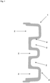
- the profile structure 1 has at least two beads 2, for example the 1 profile structure 1 shown has five beads 2 .
- the beads 2 are formed by channel-shaped depressions, which are preferably formed one above the other and with side walls which are formed essentially parallel.
- This in 1 illustrated embodiment of the invention has, for example, three beads 2, which are open in the direction of the left half of the figure, and two beads 2, which are open in the direction of the right half of the figure. Overall, the in 1 cutting arm shown thus five beads 2 on.
- the profile structure 1 has profile structure walls 4, which can have different thicknesses.
- the profile structure walls 4 can be made thicker in the transition areas between a bead and a profile surface of the profile structure 1 than in the area of the side walls of the beads 2.
- the outwardly facing surfaces of the component 20 of the machine tool 10 are preferably referred to as profile surfaces within the meaning of the invention.
- This in 1 The illustrated embodiment of the invention essentially represents a basic structure 5 of the profile structure 1, wherein the 1 Profile structure 1 shown has no stiffening ribs 3, for example.
- the beads 2 are in the in 1 illustrated embodiment of the invention opened on the left and closed on the right side of the figure.
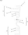
- This in 2 illustrated embodiment of the invention has a total of three beads 2, with two beads 2 are open in the direction of the left half of the figure and a bead 2 is open in the direction of the right half of the figure.
- the beads 2 and their dimensions are represented in the figures by curly brackets.
- stiffening ribs 3 which are preferably present in the beads 2 arranged.
- the stiffening ribs 3 give the profile structure 1 even greater stability and robustness.
- four stiffening ribs 3 can be seen.
- the remaining structure, which does not form a stiffening rib 3, is the basic structure 5 of the profile structure 1.
- the profile structure 1 In 3 an alternative or third embodiment of the profile structure 1 is shown.
- the 3 Profile structure 1 shown has two beads 2 and a row of stiffening ribs 3 .
- This in 3 illustrated embodiment of the invention also has a total of three beads 2, two beads 2 are open in the direction of the left half of the image and a bead 2 is open in the direction of the right half of the image.
- the beads 2 there are a number of stiffening ribs 3 which give the profile structure 1 even greater stability.
- FIG. 5 shows side views of preferred embodiments of the cutting arm 50.
- FIG 4 how the cutting arm 50 performs a torsion about a central axis D of the cutting arm 50 while in FIGS figure 5 and 6 Bends around a vertical ( figure 5 ) or a horizontal ( 6 ) Axis of the cutting arm 50 are shown.
- the central axis, as well as the vertical and horizontal axes of the cutting arm 50 are in the Figures 4 to 6 represented by dashed lines passing through the cutting arm 50 or lying within the cutting arm 50.
- the directions of bending or rotation of the cutting arm 50 for each type of load are shown in FIGS Figures 4 to 6 indicated by the round arrows at the ends of the axes.
- figure 4 12 also shows the three axes A, B and C, which can pass through different points of the cutting arm 50.
- the first axis A represents the motor axis of the machine tool 10.
- the second axis B represents the transmission axis of the machine tool 10 and is connected to one of the two pulleys of the belt drive of the machine tool 10.
- the third axis C represents the tool axis of the machine tool 10 and is connected to the other of the two pulleys of the belt drive of the machine tool 10 .
- the tool 11 of the machine tool 10 can rotate about the third or tool axis C of the proposed cutting arm 50 .
- the tool 11 can preferably be a disk-shaped tool, such as a separating or cutting disk, wherein the tool 11 is set up to rotate about the tool axis C. Furthermore, is in figure 4 the angle alpha is shown, which is preferably enclosed by the stiffening ribs 3 and the beads 2 or the stiffening ribs 3 and the torsion axis of the cutting arm 50 . In particular, the torsion axis of the cutting arm 50 coincides with the virtual central axis D of the cutting arm 50 .
Abstract
Die vorliegende Erfindung betrifft eine Profilstruktur für ein Bauteil einer Werkzeugmaschine, wobei die Profilstruktur mindestens zwei Sicken aufweist. In einem zweiten Aspekt betrifft die Erfindung eine Werkzeugmaschine mit einem Bauteil, das eine vorgeschlagene Profilstruktur umfasst. Bei der Werkzeugmaschine kann es sich vorzugsweise um ein Schneid- oder Trenngerät handeln, wobei das Bauteil der Werkzeugmaschine ein Schneidarm sein kann. Die Profilstruktur ist besonders gut geeignet, um unterschiedliche Belastungen, denen ein Bauteil einer Werkzeugmaschine ausgesetzt sein kann, auszuhalten. Bei den Belastungen kann es sich beispielsweise um Biegungen um eine horizontale oder um eine vertikale Achse handeln oder um Torsionen. In einem weiteren Aspekt betrifft die Erfindung einen Schneidarm für eine Werkzeugmaschine, wobei der Schneidarm eine vorgeschlagene Profilstruktur umfasst. Der Schneidarm kann insbesondere einteilig ausgebildet sein.The present invention relates to a profile structure for a component of a machine tool, the profile structure having at least two beads. In a second aspect, the invention relates to a machine tool with a component that includes a proposed profile structure. The machine tool can preferably be a cutting or separating device, in which case the component of the machine tool can be a cutting arm. The profile structure is particularly well suited to withstand different loads to which a component of a machine tool can be exposed. The loads can be, for example, bending around a horizontal or vertical axis or torsion. In a further aspect, the invention relates to a cutting arm for a machine tool, the cutting arm comprising a proposed profile structure. The cutting arm can in particular be designed in one piece.
Description
Die vorliegende Erfindung betrifft eine Profilstruktur für ein Bauteil einer Werkzeugmaschine, wobei die Profilstruktur mindestens zwei Sicken aufweist. In einem weiteren Aspekt betrifft die Erfindung eine Werkzeugmaschine mit einem Bauteil, das eine vorgeschlagene Profilstruktur umfasst. Bei der Werkzeugmaschine kann es sich vorzugsweise um ein Schneid- oder Trenngerät handeln, wobei das Bauteil der Werkzeugmaschine ein Schneidarm sein kann. Die Profilstruktur ist besonders gut geeignet, um unterschiedliche Belastungen, denen ein Bauteil einer Werkzeugmaschine ausgesetzt sein kann, auszuhalten. Bei den Belastungen kann es sich beispielsweise um Biegungen um eine horizontale oder um eine vertikale Achse handeln oder um Torsionen. In einem weiteren Aspekt betrifft die Erfindung einen Schneidarm für eine Werkzeugmaschine, wobei der Schneidarm eine vorgeschlagene Profilstruktur umfasst und vorzugsweise einteilig ausgebildet ist.The present invention relates to a profile structure for a component of a machine tool, the profile structure having at least two beads. In a further aspect, the invention relates to a machine tool with a component that includes a proposed profile structure. The machine tool can preferably be a cutting or separating device, in which case the component of the machine tool can be a cutting arm. The profile structure is particularly well suited to withstand different loads to which a component of a machine tool can be exposed. The loads can be, for example, bending around a horizontal or vertical axis or torsion. In a further aspect, the invention relates to a cutting arm for a machine tool, wherein the cutting arm comprises a proposed profile structure and is preferably designed in one piece.
Die Erfindung ist auf dem technischen Gebiet der Werkzeugmaschinen angesiedelt, insbesondere im Gebiet der Schneid- oder Trenngerät. Dort sind vor allem benzinbetriebene Geräte bekannt, beispielsweise Trennschleifer, deren Schleifscheibe von einem Verbrennungsmotor angetrieben wird, wobei die Übertragung einer Bewegung von einem Motor des Trennschleifers zur Trennscheibe häufig mit einem Riemenantrieb erfolgt. Um den bei der Arbeit mit der Werkzeugmaschine anfallenden Staub aufzufangen, sind Schneid- oder Trenngeräte oftmals mit einer Schutzhaube versehen, an der beispielsweise eine Öffnung zur Anbringung einer Staubabsaugung vorgesehen sein kann. Für die ausragende Schutzhaubenbefestigung haben Trennschleifer eine Schneidarm, der eine erste Einheit der Werkzeugmaschine aus Motor und Griff mit einer zweiten Einheit aus Schutzhaube und Trennscheibe miteinander verbindet. Dieser Schneidarm kann während des Betriebs der Werkzeugmaschine so hohen Belastungen ausgesetzt sein, dass es im schlimmsten Fall zu einem Bruch des Schneidarms kommen kann. Ein solcher Bruch des Schneidarms kann zu unerwünschten Verletzungen und Gefährdungen für den Nutzer der Werkzeugmaschine führen. Die mechanischen Belastungen, die den Bruch des Schneidarms hervorrufen können, können beispielsweise durch Unwuchtanregungen des schnell rotierenden Schneidblatts entstehen oder durch starke Vibrationen bei hohen Motordrehzahlen bzw. Motorgeschwindigkeiten. Der Schneidarm einer Werkzeugmaschine wird in der Literatur auch als Ausleger bezeichnet.The invention is located in the technical field of machine tools, in particular in the field of cutting or separating devices. Above all, gasoline-powered devices are known there, for example cut-off grinders, the grinding wheel of which is driven by an internal combustion engine, with the transmission of a movement from a motor of the cut-off grinder to the cutting wheel often being carried out with a belt drive. In order to collect the dust that accumulates when working with the machine tool, cutting or separating devices are often provided with a protective hood, on which, for example, an opening for attaching a dust extraction device can be provided. For the protruding guard attachment, power cutters have a cutting arm that connects a first unit of the machine tool made of motor and handle with a second unit made of guard and cutting disc. This cutting arm can be subjected to such high loads during operation of the machine tool that, in the worst case, the cutting arm can break. Such a breakage of the cutting arm can lead to undesired injuries and hazards for the user of the machine tool. The mechanical loads that can cause the cutting arm to break can be caused, for example, by unbalance excitation of the rapidly rotating cutting blade or by strong vibrations at high engine speeds or motor speeds. The cutting arm of a machine tool is also referred to as a boom in the literature.
Beispielsweise wird in der
Die Aufgabe, die der vorliegenden Erfindung zugrunde liegt, besteht darin, die vorstehend beschriebenen Mängel und Nachteile des Standes der Technik zu überwinden und eine Profilstruktur für ein Bauteil einer Werkzeugmaschine anzugeben, mit der beispielsweise ein Schneidarm mit verbesserter Stabilität und Steifigkeit gegenüber verschiedenen mechanischen Belastungen bereitgestellt werden kann. Darüber hinaus soll eine Werkzeugmaschine angegeben werden, die einen Schneidarm mit verbesserter Stabilität aufweist. Ein weiteres Anliegen der Erfindung besteht darin, das Gesamtgewicht der Werkzeugmaschine möglichst gering zu halten, d.h. eine besonders leichte Werkzeugmaschine anzugeben.The object on which the present invention is based is to overcome the above-described deficiencies and disadvantages of the prior art and to provide a profile structure for a component of a machine tool, with which, for example, a cutting arm with improved stability and rigidity against various mechanical loads is provided can be. In addition, a machine tool is to be specified which has a cutting arm with improved stability. Another concern of the invention is to keep the overall weight of the machine tool as low as possible, i.e. to specify a particularly light machine tool.
Die Aufgabe wird gelöst durch den Gegenstand der unabhängigen Ansprüche. Vorteilhafte Ausführungsformen zu dem Gegenstand der unabhängigen Ansprüche finden sich in den abhängigen Ansprüchen.The object is solved by the subject matter of the independent claims. Advantageous embodiments relating to the subject matter of the independent claims can be found in the dependent claims.
In einem ersten Aspekt betrifft die Erfindung eine Profilstruktur für ein Bauteil einer Werkzeugmaschine, wobei die Profilstruktur mindestens zwei Sicken aufweist. Im Sinne der Erfindung stellt eine Sicke bevorzugt eine rinnenförmige Vertiefung dar, die im Kontext der vorliegenden Erfindung zur Versteifung des Bauteils der Werkzeugmaschine gegenüber Verformungen oder Schwingungen verwendet wird. Die erfindungsgemäß vorgeschlagene Profilstruktur mit mindestens zwei Sicken erlaubt vorteilhafterweise eine besonders große mechanischen Stabilität gegenüber verschiedenen Belastungen. Tests haben gezeigt, dass die vorgeschlagene Profilstruktur überraschend stabil in Bezug auf Biegungen um eine horizontale oder um eine vertikale Achse oder in Bezug auf Torsionen ausgebildet ist. Die erhöhte mechanische Stabilität wird insbesondere dann sichtbar, wenn verschiedene dieser Belastungstypen zusammenwirken, so dass das Bauteil mit der entsprechenden Profilstruktur besonders stark und inhomogen beansprucht wird. Bei einer solchen Überlagerung verschiedener Belastungstypen hat sich das Bauteil mit der vorgeschlagenen Profilstruktur mit mindestens zwei Sicken vorteilhafterweise als besonders robust und widerstandsfähig gegenüber etwaigen Beschädigungen oder gar einem Bruch erwiesen.In a first aspect, the invention relates to a profile structure for a component of a machine tool, the profile structure having at least two beads. Within the meaning of the invention, a bead preferably represents a channel-shaped indentation, which is used in the context of the present invention to stiffen the component of the machine tool against deformations or vibrations. The inventively proposed profile structure with at least two beads advantageously allows a particularly high mechanical stability against different loads. Tests have shown that the proposed profile structure is surprisingly stable in terms of bending around a horizontal or vertical axis or in terms of torsions. The increased mechanical stability becomes particularly evident when various of these load types interact, so that the component with the corresponding profile structure is subjected to particularly high and inhomogeneous loads. With such a superimposition of different types of loads, the component with the proposed profile structure with at least two beads has advantageously proven to be particularly robust and resistant to any damage or even breakage.
Es ist im Sinne der Erfindung bevorzugt, dass die mindestens zwei Sicken der vorgeschlagenen Profilstruktur in Längsrichtung des Bauteils verlaufen. Die Sicken können insbesondere im Wesentlichen parallel zum Riemenantrieb der Werkzeugmaschine verlaufen, wenn die Profilstruktur beispielsweise einen Schneidarm einer Werkzeugmaschine bildet.According to the invention, it is preferred that the at least two beads of the proposed profile structure run in the longitudinal direction of the component. In particular, the beads can run essentially parallel to the belt drive of the machine tool if the profile structure forms a cutting arm of a machine tool, for example.
In einem zweiten Aspekt betrifft die Erfindung einen Schneidarm für eine Werkzeugmaschine, wobei der Schneidarm eine vorgeschlagene Profilstruktur mit mindestens zwei Sicken umfasst. Der Schneidarm ist vorzugsweise einteilig ausgebildet. Es ist im Sinne der Erfindung bevorzugt, dass der vorgeschlagene Schneidarm ein Bauteil der Werkzeugmaschine im Sinne der Erfindung darstellt. In einer besonders bevorzugten Ausgestaltung betrifft die Erfindung einen Schneidarm für eine Werkzeugmaschine, wobei der Schneidarm eine Profilstruktur mit mindestens zwei Sicken aufweist und der Schneidarm einteilig ausgebildet ist. Der Begriff der Einteiligkeit bedeutet im Sinne der Erfindung bevorzugt, dass ein Motorgehäuse der Werkzeugmaschine und das Bauteil eine Einheit bilden. Tests haben gezeigt, dass einteilige Schneidarme bei gleichem Gewicht zumeist eine höhere mechanische Stabilität aufweisen als gleichschwere zweiteilig ausgebildete Schneidarme. Außerdem werden keine Schnittstellen benötigt, die oft aufwändig zu integrieren sind und die mechanische Stabilität weiter verringern können.In a second aspect, the invention relates to a cutting arm for a machine tool, the cutting arm comprising a proposed profile structure with at least two beads. The cutting arm is preferably designed in one piece. It is preferred within the meaning of the invention that the proposed cutting arm represents a component of the machine tool within the meaning of the invention. In a particularly preferred embodiment, the invention relates to a cutting arm for a machine tool, the cutting arm having a profile structure with at least two beads and the cutting arm being formed in one piece. In the context of the invention, the concept of one-piece preferably means that a motor housing of the machine tool and the component form a unit. Tests have shown that, for the same weight, one-piece cutting arms usually have greater mechanical stability than two-piece cutting arms of the same weight. In addition, no interfaces are required, which are often complex to integrate and can further reduce the mechanical stability.
Indem das vorgeschlagene Bauteil einteilig ausgebildet ist, wendet es sich gerade von mehrteiligen Schneidarmen oder Auslegern, wie sie aus dem Stand der Technik bekannt sind, ab.Since the proposed component is designed in one piece, it turns away from multi-part cutting arms or extension arms, as are known from the prior art.
Vorteilhafterweise kann das Bauteil durch die Vorsehung der mindestens zwei Sicken besonders leicht ausgestaltet werden, so dass insgesamt eine Werkzeugmaschine mit geringen Gesamtgewicht bereitgestellt werden kann.Advantageously, the component can be made particularly light by providing the at least two beads, so that overall a machine tool with a low overall weight can be provided.
Die Ausbildung der mindestens zwei Sicken wird vorzugsweise in einer Schnittdarstellung des Bauteils der Werkzeugmaschine sichtbar. Wenn es sich bei dem Bauteil um einen Schneidarm eines Trennschleifers handelt, kann eine erste virtuelle Achse innerhalb des Schneidarms verlaufen. Im Wesentlichen senkrecht zu dieser ersten virtuellen Achse kann eine vertikale Schnittebene verlaufen. Wenn der Schneidarm entlang dieser vertikalen Schnittebene geschnitten und die resultierende Darstellung abgebildet wird, ergeben sich Figuren, wie
Die vorgeschlagene Profilstruktur stellt vorzugsweise eine feingliedrige Struktur zur Lastaufnahme dar, die insbesondere verschiedene Ansätze aus der Festigkeitslehre in sich vereint. Die vorgeschlagene Profilstruktur stellt insbesondere eine nicht-naheliegende Kombination aus einem stehenden Doppel-T-Trägerprofil, einem liegenden, d.h. im Vergleich zum stehenden Doppel-T-Trägerprofil um im Wesentlichen 90 Grad gedrehten, Doppel-T-Trägerprofil und einem dünnwandigen Rohr dar, wobei das stehende Doppel-T-Trägerprofil besonders stabil gegenüber Biegungen um die horizontale Achse ausgebildet ist, das liegende Doppel-T-Trägerprofil besonders stabil gegenüber Biegungen um die vertikale Achse ausgebildet ist und das dünnwandige Rohr besonders widerstandkräftig und robust gegenüber Torsionen ausgebildet ist. Die Kombination dieser bekannten Profile war für den Fachmann nicht naheliegend, weil keines der genannten Profile zwei oder mehr Sicken aufweist. Vielmehr zeigt das Profil, welches als dünnwandiges Rohr ausgebildet ist, gerade von dem erfindungsgemäßen Profil mit den zwei Sicken weg, denn offensichtlich weist ein dünnwandiges Rohr überhaupt gar keine Vertiefungen oder Ähnliches auf. Stattdessen ist die Oberfläche eines dünnwandigen Rohres in der Regel homogen ohne Dellen oder hervorstehende Elemente ausgebildet. Insofern wendet sich die vorgeschlagene Profilstruktur durch die Vorsehung der mindestens zwei Sicken gerade vom Stand der Technik ab.The proposed profile structure preferably represents a slender structure for absorbing loads, which in particular combines various approaches from the theory of strength. The proposed profile structure represents, in particular, a non-obvious combination of a standing I-beam profile, a horizontal I-beam profile, i.e. rotated by essentially 90 degrees compared to the standing I-beam profile, and a thin-walled tube, the upright I-beam profile is designed to be particularly stable with respect to bending around the horizontal axis, the horizontal I-beam profile is designed to be particularly stable with regard to bending around the vertical axis and the thin-walled tube is designed to be particularly resistant and robust to torsion. The combination of these known profiles was not obvious to the person skilled in the art because none of the profiles mentioned has two or more beads. Rather, the profile, which is designed as a thin-walled tube, shows precisely the profile according to the invention with the two beads away, because obviously a thin-walled pipe has no indentations or the like at all. Instead, the surface of a thin-walled tube is usually homogeneous without dents or protruding elements. In this respect, the proposed profile structure differs from the prior art by the provision of the at least two beads.
Bei der Biegung um die horizontale Achse verläuft die die horizontale Achse vorzugsweise im Wesentlichen senkrecht zu einer Fläche des Schneidarms, d.h. im Wesentlichen senkrecht zu einer Ebene, die von dem Schneidarm aufgespannt wird. Vorzugsweise verläuft die die horizontale Achse auch im Wesentlichen senkrecht zu einer Ebene, die von dem bevorzugt scheibenförmigen Werkzeug der Werkzeugmaschine aufgespannt wird. Die genannten Ebenen, die von der Fläche des Schneidarms und dem bevorzugt scheibenförmigen Werkzeug der Werkzeugmaschine aufgespannt werden, sind vorzugsweise im Wesentlichen parallel ausgebildet. Eine Biegung um eine horizontale Achse des Schneidarms ist exemplarisch in
Bei der Biegung um die vertikale Achse verläuft die vertikale Achse vorzugsweise durch die Ebene, die von dem Schneidarm oder dem bevorzugt scheibenförmigen Werkzeug der Werkzeugmaschine aufgespannt wird. Mit anderen Worten liegt die die vertikale Achse in dieser Ebene, insbesondere in einer vertikalen Richtung, d.h. im Sinne der Erfindung bevorzugt von oben nach unten oder von unten nach oben. Eine Biegung um eine vertikale Achse des Schneidarms ist exemplarisch in
Bei der Torsion verläuft die Drehachse vorzugsweise innerhalb der Ebene, die von dem Schneidarm oder dem bevorzugt scheibenförmigen Werkzeug der Werkzeugmaschine aufgespannt wird, allerdings in einer horizontalen Richtung, d.h. im Sinne der Erfindung bevorzugt von vorne nach hinten oder von hinten nach vorne, wobei das Werkzeug der Werkzeugmaschine vorzugsweise den vorderen Bereich der Werkzeugmaschine markiert und der Hauptkörper der Werkzeugmaschine, der beispielsweise einen Motor oder Griffe aufweisen kann, den hinteren Bereich der Werkzeugmaschine. Eine Torsion um eine virtuelle Zentralachse des Schneidarms ist exemplarisch in
Bei der feingliedrigen Struktur, die die vorgeschlagene Profilstruktur vorzugsweise bildet, handelt es sich bevorzugt um eine balkenähnliches Struktur, die durch den Einsatz der mindestens zwei Sicken dazu eingerichtet ist, die unterschiedlichen Belastungstypen oder eine Überlagerung von ihnen optimal zu übertragen bzw. aufzunehmen. Die vorgeschlagene Profilstruktur weist aufgrund ihrer feingliedrigen Struktur und der mindestens zwei Sicken eine gewisse Elastizität auf, so dass die vorgeschlagene Profilstruktur vorteilhafterweise dazu eingerichtet ist, eine elastische Energie bzw. eine Verformungsenergie aufzunehmen. Dadurch wird das Bauteil, das eine vorgeschlagene Profilstruktur umfasst, besonders wirksam vor Beschädigungen geschützt. Die Erfindung stellt vorteilhafterweise ein dahingehend optimiertes Zusammenspiel aus Leichtbauweise und Steifigkeitslehre dar, wobei die Erfinder eine besonders ausgewogene Kombination aus leichter Herstellbarkeit, mechanischer Stabilität, geringem Gewicht und Robustheit gefunden haben. Insbesondere stellt die Erfindung eine Kombination der theoretisch optimalen Querschnitte eines Schnittarms dar, die aufgrund ihrer feingliedrigen Struktur und der mindestens zwei Sicken besonders gut geeignet ist, die Lasten der unterschiedlichen Belastungstypen bzw. einer möglichen Kombination der verschiedenen Belastungstypen besonders gut aufzunehmen bzw. auszuhalten. Auf diese Weise wird das Bauteil mit der vorgeschlagenen Profilstruktur besonders wirksam gegen Bruch und anderen mechanische Beeinträchtigungen geschützt.The delicate structure, which preferably forms the proposed profile structure, is preferably a beam-like structure which, through the use of the at least two beads, is designed to optimally transfer or absorb the different types of loads or a superimposition of them. The proposed profile structure has a certain elasticity due to its delicate structure and the at least two beads, so that the proposed profile structure is advantageously set up to absorb elastic energy or deformation energy. As a result, the component, which includes a proposed profile structure, is protected against damage in a particularly effective manner. The invention advantageously represents a combination of lightweight construction and stiffness theory that has been optimized to this effect, with the inventors having found a particularly balanced combination of ease of manufacture, mechanical stability, low weight and robustness. In particular, the invention represents a combination of the theoretically optimal cross-sections of a cutting arm which, due to its delicate structure and the at least two beads, is particularly well suited to absorbing or withstanding the loads of the different load types or a possible combination of the different load types particularly well. In this way, the component with the proposed profile structure is protected particularly effectively against breakage and other mechanical damage.
Es ist im Sinne der Erfindung bevorzugt, dass die Profilstruktur Versteifungsrippen aufweist. Diese Versteifungsrippen können insbesondere in den Sicken angeordnet vorliegen. Durch die Vorsehung der Versteifungsrippen kann die Profilstruktur weiter verstärkt werden. Außerdem können Schübe zwischen den unterschiedlichen Bereichen des Bauteils besonders gut übertragen werden. Es stellt einen wesentlichen Vorteil der Erfindung dar, dass aufgrund dieser Schubfelder die aus Leichtbau-Gesichtspunkten ungünstigen Belastungsformen «Biegung» und «Torsion» in die günstigeren, weil besser auszuhaltenden Belastungsformen «Zug» oder «Druck» umgelenkt werden können. Dadurch kann das Bauteil besonders robust und steif ausgebildet werden.According to the invention, it is preferred that the profile structure has stiffening ribs. These stiffening ribs can be arranged in particular in the beads. The profile structure can be further reinforced by the provision of the stiffening ribs. In addition, thrusts between the different areas of the component can be transferred particularly well. It is a significant advantage of the invention that, due to these shear fields, the unfavorable “bending” and “torsion” load forms from the point of view of lightweight construction can be redirected to the more favorable “tension” or “compression” load forms because they are easier to withstand. As a result, the component can be made particularly robust and stiff.
Es ist im Sinne der Erfindung bevorzugt, dass die Versteifungsrippen mit den Sicken einen Winkel alpha einschließen, wobei der Winkel alpha in einem Bereich von 30 bis 60 ° liegt. Vorzugsweise können die Versteifungsrippen in einem 30 bis 60°-Winkel zu den Sicken versetzt verlaufen. Die Formulierung, dass «die Versteifungsrippen mit den Sicken einen Winkel alpha einschließen» bedeutet im Sinne der Erfindung insbesondere, dass ein die Versteifungsrippen einen Winkel mit einer virtuellen Zentralachse des Schneidarms einschließen, wobei dieser Winkel in einem Bereich von 30 bis 60 ° liegen kann. Beispielsweise können die Versteifungsrippen in einem 45° Winkel zu den Sicken versetzt verlaufen. Die Versteifungsrippen verlaufen insbesondere schräg innerhalb der Sicken, wobei ein Grad für die Geneigtheit der Versteifungsrippen von dem Winkel alpha angegeben werden kann.According to the invention, it is preferred that the stiffening ribs enclose an angle alpha with the beads, the angle alpha being in a range of 30 to 60°. The stiffening ribs can preferably run offset at an angle of 30 to 60° to the beads. The wording that "the stiffening ribs form an angle alpha with the beads" means in the context of the invention in particular that the stiffening ribs form an angle with a virtual central axis of the cutting arm, with this angle being in a range of 30 to 60°. For example, the stiffening ribs can run offset at a 45° angle to the beads. The stiffening ribs run, in particular, obliquely within the beads, it being possible for a degree for the inclination of the stiffening ribs to be specified by the angle alpha.
Es ist im Sinne der Erfindung bevorzugt, dass die Profilstruktur eine Sandwich-Struktur bildet. Insbesondere durch die vorzugsweise feingliedrige, tragende Profilstruktur, die mindestens zwei Sicken aufweist, und die bevorzugt dünnwandigen Versteifungsrippen bzw. Versteifungen kann der Sandwich-Effekt erreicht werden, der zu der besonders hohen mechanischen Stabilität und Robustheit der vorgeschlagenen Profilstruktur bzw. des vorgeschlagenen Bauteils beiträgt. Insbesondere ermöglicht die Ausgestaltung der vorgeschlagenen Profilstruktur einen optimierten Kraftfluss innerhalb des Bauteils. Ein optimierter oder idealer Kraftfluss ist im Sinne der Erfindung dadurch gekennzeichnet, dass überwiegend Zug- oder Druckbelastungen in Bezug auf das Bauteil der Werkzeugmaschine auftreten. Tests haben gezeigt, dass die auftretenden Lasten und/oder Belastungen durch die Erfindung, insbesondere die Vorsehung der mindestens zwei Sicken, besonders gleichmäßig in dem Bauteil der Werkzeugmaschine, welches die vorgeschlagene Profilstruktur aufweist, verteilt wird. Mit anderen Worten wird mit der Erfindung eine besonders homogene Materialbelastung ermöglicht, die wirksam gegenüber etwaigen, ungewünschten Brüchen oder mechanischen Beeinträchtigungen des Bauteils vorbeugt.According to the invention, it is preferred that the profile structure forms a sandwich structure. In particular, by the preferably slender, supporting profile structure, which has at least two Has beads, and the preferably thin-walled stiffening ribs or stiffeners, the sandwich effect can be achieved, which contributes to the particularly high mechanical stability and robustness of the proposed profile structure or the proposed component. In particular, the design of the proposed profile structure enables an optimized flow of forces within the component. According to the invention, an optimized or ideal flow of forces is characterized in that predominantly tensile or compressive loads occur in relation to the component of the machine tool. Tests have shown that the loads and/or stresses that occur are distributed particularly evenly in the component of the machine tool that has the proposed profile structure as a result of the invention, in particular the provision of the at least two beads. In other words, a particularly homogeneous material load is made possible with the invention, which effectively prevents any undesired fractures or mechanical impairments of the component.
Es ist im Sinne der Erfindung bevorzugt, dass die Profilstruktur und/oder die Versteifungsrippen über die gesamte Länge des Bauteils der Werkzeugmaschine geschlossen vorliegen. Es kann allerdings im Sinne der Erfindung auch bevorzugt sein, dass die Profilstruktur und/oder die Versteifungsrippen nicht über die gesamte Länge des Bauteils der Werkzeugmaschine geschlossen vorliegen. In diesem letzten Fall können sie beispielsweise teilweise offen und teilweise geschlossen vorliegen über die Länge des Bauteils. Beispielsweise kann das Bauteil perforierte, gelochte und/oder ausgeschnittene Strukturen oder Teilbereiche umfassen, ohne darauf beschränkt zu sein.According to the invention, it is preferred that the profile structure and/or the stiffening ribs are closed over the entire length of the component of the machine tool. However, within the meaning of the invention, it can also be preferred that the profile structure and/or the stiffening ribs are not closed over the entire length of the component of the machine tool. In this last case they can be, for example, partially open and partially closed over the length of the component. For example, the component can include perforated, punched and/or cut out structures or sections, without being limited thereto.
Es ist im Sinne der Erfindung bevorzugt, dass die Profilstruktur eine Profilstrukturwand umfasst. Vorzugsweise kann die Profilstrukturwand in unterschiedlichen Bereichen unterschiedliche Dicken aufweisen. Das bedeutet im Sinne der Erfindung bevorzugt, dass die Profilstrukturwand in unterschiedlichen Bereichen unterschiedlich dick ausgebildet sein kann. Der Begriff «Dicke der Profilstrukturwand» ist im Sinne der Erfindung vorzugsweise als Material- oder Wandungsstärke desjenigen Materials zu verstehen, aus dem das Bauteil der Werkzeugmaschine hergestellt ist. Es handelt sich hierbei vorzugsweise um die Dicke des Materials im Bereich der vorgeschlagenen Profilstruktur, wie sie in den
Vorzugsweise kann die Profilstrukturwand eine Dicke in einem Bereich von 1 bis 5 mm aufweisen, bevorzugt in einem Bereich von 2 bis 3 mm.The profile structure wall can preferably have a thickness in a range from 1 to 5 mm, preferably in a range from 2 to 3 mm.
Es ist im Sinne der Erfindung bevorzugt, dass die Profilstruktur und die Versteifungsrippen planar, eben und/oder geradlinig ausgebildet sind. Es kann allerdings im Sinne der Erfindung auch bevorzugt sein, dass sie davon abweichend gerade nicht planar, eben und/oder geradlinig ausgebildet sind.It is preferred within the meaning of the invention that the profile structure and the stiffening ribs are designed to be planar, level and/or rectilinear. However, within the meaning of the invention, it can also be preferred that, deviating from this, they are not designed to be planar, level and/or rectilinear.
Es ist im Sinne der Erfindung bevorzugt, dass die Profilstruktur Bereiche mit Waben- und/oder Gitterstrukturen aufweist. Das kann beispielsweise dadurch erreicht werden, dass die Rippen schräg und/oder diagonal verlaufen und auf diese Weise Waben und/oder Gitter oder andere Strukturen bilden. Es ist im Sinne der Erfindung besonders bevorzugt, dass die Rippen in den Rand- und/oder Außenbereichen der Profilstruktur bzw. des Schneidarms schräg und/oder diagonal verlaufen.It is preferred within the meaning of the invention that the profile structure has areas with honeycomb and/or lattice structures. This can be achieved, for example, in that the ribs run obliquely and/or diagonally and in this way form honeycombs and/or grids or other structures. It is particularly preferred within the meaning of the invention that the ribs run obliquely and/or diagonally in the edge and/or outer areas of the profile structure or the cutting arm.
Es ist im Sinne der Erfindung bevorzugt, dass die Profilstruktur aus mehr als einem Material gefertigt wird. Beispielsweise kann eine Grundstruktur der Profilstruktur ein Metall umfassen, während die Versteifungsrippen einen Kunststoff umfassen. Alternativ kann die Grundstruktur der Profilstruktur einen kohlenstofffaserverstärkten Kunststoff (CFK) umfassen, während die Versteifungsrippen aus einem anderen Kunststoff oder Metall gebildet sind. Als Metall kann im Kontext der vorliegenden Erfindung aufgrund seines geringen Gewichts vorzugsweise Aluminium verwendet werden. Es sind allerdings auch andere Metalle oder Legierungen möglich.It is preferred within the meaning of the invention that the profile structure is made of more than one material. For example, a basic structure of the profile structure can include a metal, while the stiffening ribs include a plastic. Alternatively, the basic structure of the profile structure can include a carbon fiber reinforced plastic (CFRP), while the stiffening ribs are formed from a different plastic or metal. Aluminum can preferably be used as the metal in the context of the present invention due to its low weight. However, other metals or alloys are also possible.
Es ist im Sinne der Erfindung ganz besonders bevorzugt, dass die vorgeschlagene Profilstruktur in Bezug auf mögliche, auftretende Eigenfrequenzen des Bauteils optimiert wird. Dazu können beispielsweise Simulationsmethoden verwendet werden, die eingesetzt werden, um die Profilstruktur des Bauteils weiter zu optimieren und eine erhöhte Steifigkeit des Bauteils zu erreichen.Within the meaning of the invention, it is particularly preferred that the proposed profile structure is optimized with regard to possible natural frequencies that occur in the component. For this purpose, simulation methods can be used, for example, which are used to further optimize the profile structure of the component and to achieve increased component rigidity.
Es ist im Sinne der Erfindung bevorzugt, dass die Profilstruktur und/oder das Bauteil Dämpfungsmittel zur Schwingungsdämpfung aufweist/aufweisen. Diese Dämpfungsmittel können beispielsweise lokal, d.h. örtlich begrenzt, vorgesehen sein oder großflächig in einem großen Bereich des Bauteils der Werkzeugmaschine.It is preferred within the meaning of the invention that the profile structure and/or the component has/have damping means for vibration damping. These damping means can, for example, be provided locally, i.e. locally limited, or over a large area in a large area of the component of the machine tool.
In einem weiteren Aspekt betrifft die Erfindung eine Werkzeugmaschine mit einem Bauteil, das eine Profilstruktur mit mindestens zwei Sicken umfasst. Die Definitionen, technischen Wirkungen und Vorteile, die für die Profilstruktur und das Bauteil beschrieben wurden, gelten für die vorgeschlagene Werkzeugmaschine analog. Es ist im Sinne der Erfindung bevorzugt, dass das Bauteil ein Schneidarm für eine Werkzeugmaschine ist, wobei der Schneidarm einteilig ausgebildet ist. Vorzugsweise ist die Werkzeugmaschine ein Schneid- oder Trenngerät, wobei die Werkzeugmaschine bevorzugt ein scheibenförmiges Werkzeug aufweist. Das scheibenförmige Werkzeug kann insbesondere eine Trennscheibe oder ein Schneidblatt sein, wobei das bevorzugt scheibenförmige Werkzeug vorzugsweise in einem vorderen Bereich der Werkzeugmaschine bzw. des Schneidarms der Werkzeugmaschine angeordnet vorliegt.In a further aspect, the invention relates to a machine tool with a component that includes a profile structure with at least two beads. The definitions, technical effects and advantages that have been described for the profile structure and the component apply analogously to the proposed machine tool. It is preferred within the meaning of the invention that the component is a cutting arm for a machine tool, with the cutting arm being formed in one piece is. The machine tool is preferably a cutting or separating device, with the machine tool preferably having a disc-shaped tool. The disk-shaped tool can in particular be a cutting disk or a cutting blade, the preferably disk-shaped tool being preferably arranged in a front area of the machine tool or the cutting arm of the machine tool.
Weitere Vorteile ergeben sich aus der folgenden Figurenbeschreibung. Die Figuren, die Beschreibung und die Ansprüche enthalten zahlreiche Merkmale in Kombination. Der Fachmann wird die Merkmale zweckmäßigerweise auch einzeln betrachten und zu sinnvollen weiteren Kombinationen zusammenfassen.Further advantages result from the following description of the figures. The figures, the description and the claims contain numerous features in combination. The person skilled in the art will expediently also consider the features individually and combine them into further meaningful combinations.
In den Figuren sind gleiche und gleichartige Komponenten mit gleichen Bezugszeichen beziffert. Es zeigen:
- Fig. 1
- Darstellung eines vertikalen Schnitts durch ein Bauteil einer Werkzeugmaschine, wobei durch den vertikalen Schnitt eine bevorzugte Ausgestaltung der Profilstruktur sichtbar wird.
- Fig. 2
- Darstellung eines vertikalen Schnitts durch ein Bauteil einer Werkzeugmaschine, wobei durch den vertikalen Schnitt eine zweite bevorzugte Ausgestaltung der Profilstruktur sichtbar wird.
- Fig. 3
- Darstellung eines vertikalen Schnitts durch ein Bauteil einer Werkzeugmaschine, wobei durch den vertikalen Schnitt eine zweite bevorzugte Ausgestaltung der Profilstruktur sichtbar wird.
- Fig. 4
- Seitenansicht einer bevorzugten Ausführungsform des Schneidarms, wobei der Schneidarm eine Torsion um eine Zentralachse durchführt
- Fig. 5
- Seitenansicht einer bevorzugten Ausführungsform des Schneidarms, wobei der Schneidarm eine Biegung um eine vertikale Achse durchführt
- Fig. 6
- Seitenansicht einer bevorzugten Ausführungsform des Schneidarms, wobei der Schneidarm eine Biegung um eine horizontale Achse durchführt
- 1
- Representation of a vertical section through a component of a machine tool, whereby a preferred configuration of the profile structure becomes visible through the vertical section.
- 2
- Representation of a vertical section through a component of a machine tool, a second preferred embodiment of the profile structure becoming visible through the vertical section.
- 3
- Representation of a vertical section through a component of a machine tool, a second preferred embodiment of the profile structure becoming visible through the vertical section.
- 4
- Side view of a preferred embodiment of the cutting arm, wherein the cutting arm performs torsion about a central axis
- figure 5
- Side view of a preferred embodiment of the cutting arm, wherein the cutting arm performs a flexion about a vertical axis
- 6
- Side view of a preferred embodiment of the cutting arm, wherein the cutting arm performs a flexion about a horizontal axis
Die Figuren zeigen bevorzugte Ausführungsformen der vorgeschlagenen Profilstruktur 1. Insbesondere sind in den Figuren vertikale Schnitte durch ein Bauteil 20 einer Werkzeugmaschine 10 dargestellt, wobei durch diese Darstellung des vertikalen Schnitts die Profilstruktur 1 des Bauteils 20 der Werkzeugmaschine 10 sichtbar wird. Die Profilstruktur 1 weist mindestens zwei Sicken 2 auf, wobei beispielsweise die in
In
Darüber hinaus umfasst die in
In
Die
- 11
- Profilstrukturprofile structure
- 22
- Sickebead
- 33
- Versteifungsrippestiffening rib
- 44
- Profilstrukturwandprofile structure wall
- 55
- Grundstrukturbasic structure
- 1010
- Werkzeugmaschinemachine tool
- 1111
- WerkzeugTool
- 2020
- Bauteilcomponent
- 5050
- Schneidarmcutting arm
- AA
- erste Achse, Motorachsefirst axis, motor axis
- BB
- zweite Achse, Getriebeachsesecond axis, gear axis
- CC
- dritte Achse, Werkzeugachsethird axis, tool axis
- DD
- virtuelle Zentralachse des Schneidarms alpha Winkel zwischen Versteifungsrippen und Sicken bzw. virtueller Zentralachsevirtual central axis of the cutting arm alpha angle between stiffening ribs and beads or virtual central axis
Claims (15)
Priority Applications (2)
| Application Number | Priority Date | Filing Date | Title |
|---|---|---|---|
| EP21192816.3A EP4140647A1 (en) | 2021-08-24 | 2021-08-24 | Profile structure for a component of a machine tool and machine tool with a profile structure |
| PCT/EP2022/072173 WO2023025577A1 (en) | 2021-08-24 | 2022-08-08 | Profiled structure for a component of a power tool, and power tool having a profiled structure |
Applications Claiming Priority (1)
| Application Number | Priority Date | Filing Date | Title |
|---|---|---|---|
| EP21192816.3A EP4140647A1 (en) | 2021-08-24 | 2021-08-24 | Profile structure for a component of a machine tool and machine tool with a profile structure |
Publications (1)
| Publication Number | Publication Date |
|---|---|
| EP4140647A1 true EP4140647A1 (en) | 2023-03-01 |
Family
ID=77465898
Family Applications (1)
| Application Number | Title | Priority Date | Filing Date |
|---|---|---|---|
| EP21192816.3A Withdrawn EP4140647A1 (en) | 2021-08-24 | 2021-08-24 | Profile structure for a component of a machine tool and machine tool with a profile structure |
Country Status (2)
| Country | Link |
|---|---|
| EP (1) | EP4140647A1 (en) |
| WO (1) | WO2023025577A1 (en) |
Citations (4)
| Publication number | Priority date | Publication date | Assignee | Title |
|---|---|---|---|---|
| US7137877B2 (en) * | 2003-06-06 | 2006-11-21 | Andreas Stihl Ag & Co Kg | Manually operated tool |
| DE102016013907A1 (en) | 2016-11-22 | 2018-05-24 | Andreas Stihl Ag & Co. Kg | Hand-held implement |
| EP3620262A1 (en) * | 2018-09-10 | 2020-03-11 | Hilti Aktiengesellschaft | Hand-held abrasive cut-off machine |
| EP3670078A1 (en) * | 2018-12-21 | 2020-06-24 | Hilti Aktiengesellschaft | Hand-held abrasive cut-off machine |
Family Cites Families (1)
| Publication number | Priority date | Publication date | Assignee | Title |
|---|---|---|---|---|
| US8413645B2 (en) * | 2005-03-23 | 2013-04-09 | Husqvarna Ab | Cutting or sawing machine |
-
2021
- 2021-08-24 EP EP21192816.3A patent/EP4140647A1/en not_active Withdrawn
-
2022
- 2022-08-08 WO PCT/EP2022/072173 patent/WO2023025577A1/en active Application Filing
Patent Citations (4)
| Publication number | Priority date | Publication date | Assignee | Title |
|---|---|---|---|---|
| US7137877B2 (en) * | 2003-06-06 | 2006-11-21 | Andreas Stihl Ag & Co Kg | Manually operated tool |
| DE102016013907A1 (en) | 2016-11-22 | 2018-05-24 | Andreas Stihl Ag & Co. Kg | Hand-held implement |
| EP3620262A1 (en) * | 2018-09-10 | 2020-03-11 | Hilti Aktiengesellschaft | Hand-held abrasive cut-off machine |
| EP3670078A1 (en) * | 2018-12-21 | 2020-06-24 | Hilti Aktiengesellschaft | Hand-held abrasive cut-off machine |
Also Published As
| Publication number | Publication date |
|---|---|
| WO2023025577A1 (en) | 2023-03-02 |
Similar Documents
| Publication | Publication Date | Title |
|---|---|---|
| EP0453773B1 (en) | Wrecking device | |
| DE102010015404B4 (en) | Method for repairing a rotor assembly of a turbomachine, ring element for a rotor assembly of a turbomachine and rotor assembly for a turbomachine | |
| EP3356073B1 (en) | Band saw blade having a chip-splitting tooth | |
| EP1894655A1 (en) | Milling tool for chip removing machining of workpieces | |
| DE102009035232B4 (en) | Cutting set for hair clippers | |
| DE102011016662A1 (en) | Tool with predetermined breaking point | |
| CH651236A5 (en) | DEVICE FOR CUTTING SAW TEETH IN LONGITUDE OR BAND SAW BLADES. | |
| DE102016112748A1 (en) | Large manipulator with weight-optimized articulated mast | |
| EP4140647A1 (en) | Profile structure for a component of a machine tool and machine tool with a profile structure | |
| EP3637978B1 (en) | Double knife cutting system | |
| EP2574226B1 (en) | Mowing finger assembly | |
| EP3664593B1 (en) | Knife blade for a cutting knife of an agricultural harvesting machine | |
| DE202020101673U1 (en) | Chainsaw with high efficiency | |
| DE3906351C2 (en) | Knife blade for mower blades of harvesting machines | |
| EP1745689B1 (en) | Apparatus preferably for lawn, garden respectively yard care, damping device and damping element | |
| DE3410368A1 (en) | TOOL FOR CULTIVATORS | |
| DE102009007187A1 (en) | Saw chain and chain saw equipped therewith | |
| DE102010017656B4 (en) | Device for cutting and cutting cuttings | |
| DE102007050385B4 (en) | Hair removal device | |
| EP2166158B1 (en) | Intake screen for water removal structures, for example hydro-electric plants | |
| DE102010002935B4 (en) | bar screen | |
| DE102020115814A1 (en) | Backhoe bucket with reinforcement | |
| DE3050788C2 (en) | Single toggle jaw crusher | |
| DE102012111842A1 (en) | Tooth for a bucket, in particular for a bucket wheel excavator | |
| DE202024100908U1 (en) | Reciprocating saw blade |
Legal Events
| Date | Code | Title | Description |
|---|---|---|---|
| PUAI | Public reference made under article 153(3) epc to a published international application that has entered the european phase |
Free format text: ORIGINAL CODE: 0009012 |
|
| STAA | Information on the status of an ep patent application or granted ep patent |
Free format text: STATUS: THE APPLICATION HAS BEEN PUBLISHED |
|
| AK | Designated contracting states |
Kind code of ref document: A1 Designated state(s): AL AT BE BG CH CY CZ DE DK EE ES FI FR GB GR HR HU IE IS IT LI LT LU LV MC MK MT NL NO PL PT RO RS SE SI SK SM TR |
|
| STAA | Information on the status of an ep patent application or granted ep patent |
Free format text: STATUS: THE APPLICATION IS DEEMED TO BE WITHDRAWN |
|
| 18D | Application deemed to be withdrawn |
Effective date: 20230902 |