EP4140606A1 - Spray containment systems and welding gun nozzle cleaning systems including spray containment systems - Google Patents
Spray containment systems and welding gun nozzle cleaning systems including spray containment systems Download PDFInfo
- Publication number
- EP4140606A1 EP4140606A1 EP22191440.1A EP22191440A EP4140606A1 EP 4140606 A1 EP4140606 A1 EP 4140606A1 EP 22191440 A EP22191440 A EP 22191440A EP 4140606 A1 EP4140606 A1 EP 4140606A1
- Authority
- EP
- European Patent Office
- Prior art keywords
- nozzle
- enclosure
- baffle
- spray
- fluid
- Prior art date
- Legal status (The legal status is an assumption and is not a legal conclusion. Google has not performed a legal analysis and makes no representation as to the accuracy of the status listed.)
- Pending
Links
Images


Classifications
-
- B—PERFORMING OPERATIONS; TRANSPORTING
- B23—MACHINE TOOLS; METAL-WORKING NOT OTHERWISE PROVIDED FOR
- B23K—SOLDERING OR UNSOLDERING; WELDING; CLADDING OR PLATING BY SOLDERING OR WELDING; CUTTING BY APPLYING HEAT LOCALLY, e.g. FLAME CUTTING; WORKING BY LASER BEAM
- B23K9/00—Arc welding or cutting
- B23K9/32—Accessories
- B23K9/328—Cleaning of weld torches, i.e. removing weld-spatter; Preventing weld-spatter, e.g. applying anti-adhesives
-
- B—PERFORMING OPERATIONS; TRANSPORTING
- B05—SPRAYING OR ATOMISING IN GENERAL; APPLYING FLUENT MATERIALS TO SURFACES, IN GENERAL
- B05B—SPRAYING APPARATUS; ATOMISING APPARATUS; NOZZLES
- B05B1/00—Nozzles, spray heads or other outlets, with or without auxiliary devices such as valves, heating means
- B05B1/28—Nozzles, spray heads or other outlets, with or without auxiliary devices such as valves, heating means with integral means for shielding the discharged liquid or other fluent material, e.g. to limit area of spray; with integral means for catching drips or collecting surplus liquid or other fluent material
-
- B—PERFORMING OPERATIONS; TRANSPORTING
- B05—SPRAYING OR ATOMISING IN GENERAL; APPLYING FLUENT MATERIALS TO SURFACES, IN GENERAL
- B05B—SPRAYING APPARATUS; ATOMISING APPARATUS; NOZZLES
- B05B12/00—Arrangements for controlling delivery; Arrangements for controlling the spray area
- B05B12/16—Arrangements for controlling delivery; Arrangements for controlling the spray area for controlling the spray area
- B05B12/32—Shielding elements, i.e. elements preventing overspray from reaching areas other than the object to be sprayed
-
- B—PERFORMING OPERATIONS; TRANSPORTING
- B05—SPRAYING OR ATOMISING IN GENERAL; APPLYING FLUENT MATERIALS TO SURFACES, IN GENERAL
- B05B—SPRAYING APPARATUS; ATOMISING APPARATUS; NOZZLES
- B05B13/00—Machines or plants for applying liquids or other fluent materials to surfaces of objects or other work by spraying, not covered by groups B05B1/00 - B05B11/00
- B05B13/02—Means for supporting work; Arrangement or mounting of spray heads; Adaptation or arrangement of means for feeding work
- B05B13/0278—Arrangement or mounting of spray heads
-
- B—PERFORMING OPERATIONS; TRANSPORTING
- B05—SPRAYING OR ATOMISING IN GENERAL; APPLYING FLUENT MATERIALS TO SURFACES, IN GENERAL
- B05B—SPRAYING APPARATUS; ATOMISING APPARATUS; NOZZLES
- B05B15/00—Details of spraying plant or spraying apparatus not otherwise provided for; Accessories
- B05B15/50—Arrangements for cleaning; Arrangements for preventing deposits, drying-out or blockage; Arrangements for detecting improper discharge caused by the presence of foreign matter
- B05B15/55—Arrangements for cleaning; Arrangements for preventing deposits, drying-out or blockage; Arrangements for detecting improper discharge caused by the presence of foreign matter using cleaning fluids
- B05B15/555—Arrangements for cleaning; Arrangements for preventing deposits, drying-out or blockage; Arrangements for detecting improper discharge caused by the presence of foreign matter using cleaning fluids discharged by cleaning nozzles
-
- B—PERFORMING OPERATIONS; TRANSPORTING
- B08—CLEANING
- B08B—CLEANING IN GENERAL; PREVENTION OF FOULING IN GENERAL
- B08B1/00—Cleaning by methods involving the use of tools
- B08B1/10—Cleaning by methods involving the use of tools characterised by the type of cleaning tool
- B08B1/16—Rigid blades, e.g. scrapers; Flexible blades, e.g. wipers
- B08B1/165—Scrapers
-
- B—PERFORMING OPERATIONS; TRANSPORTING
- B08—CLEANING
- B08B—CLEANING IN GENERAL; PREVENTION OF FOULING IN GENERAL
- B08B17/00—Methods preventing fouling
- B08B17/02—Preventing deposition of fouling or of dust
-
- B—PERFORMING OPERATIONS; TRANSPORTING
- B08—CLEANING
- B08B—CLEANING IN GENERAL; PREVENTION OF FOULING IN GENERAL
- B08B3/00—Cleaning by methods involving the use or presence of liquid or steam
- B08B3/02—Cleaning by the force of jets or sprays
-
- B—PERFORMING OPERATIONS; TRANSPORTING
- B23—MACHINE TOOLS; METAL-WORKING NOT OTHERWISE PROVIDED FOR
- B23D—PLANING; SLOTTING; SHEARING; BROACHING; SAWING; FILING; SCRAPING; LIKE OPERATIONS FOR WORKING METAL BY REMOVING MATERIAL, NOT OTHERWISE PROVIDED FOR
- B23D77/00—Reaming tools
- B23D77/14—Reamers for special use, e.g. for working cylinder ridges
-
- B—PERFORMING OPERATIONS; TRANSPORTING
- B08—CLEANING
- B08B—CLEANING IN GENERAL; PREVENTION OF FOULING IN GENERAL
- B08B17/00—Methods preventing fouling
- B08B17/02—Preventing deposition of fouling or of dust
- B08B17/06—Preventing deposition of fouling or of dust by giving articles subject to fouling a special shape or arrangement
Definitions
- This disclosure relates generally to robotic welding and, more particularly, to spray containment systems and welding gun nozzle cleaning systems including spray containment systems.
- Welding guns may accumulate spatter or other contamination during welding operations.
- Welding gun nozzle cleaning systems may include reamers, anti-spatter sprayers, and/or lubricators, to improve the operational life of the welding gun nozzle.
- Spray containment systems and welding gun nozzle cleaning systems including spray containment systems are disclosed, substantially as illustrated by and described in connection with at least one of the figures, as set forth more completely in the claims.
- Conventional anti-spatter fluid sprayers and spray containment systems sprayed anti-spatter fluid onto welding gun nozzles to slow the accumulation of spatter on the nozzle while reducing contamination of the weld cell by the sprayed anti-spatter fluid.
- Conventional sprayers and spray containment systems involved maintenance such as regular cleaning of the spray containment system to ensure performance of the spray system. Additionally, conventional spray containment systems may involve substantial manufacturing time and complexity to build.
- Example anti-spatter fluid sprayers and spray containment systems reduce the maintenance involved in using anti-spatter fluid on welding nozzle cleaning systems, reduce the complexity of the spray containment systems, and/or improve the effectiveness or performance of the spray containment system.
- Example anti-spatter fluid sprayers and spray containment systems include an enclosure, into which a welding gun nozzle may be inserted to be sprayed with anti-spatter fluid.
- Some disclosed example anti-spatter fluid sprayers and spray containment systems reduce overspray, or sprayed fluid escaping the spray containment system, by including both a top plate of an enclosure and an internal baffle positioned parallel with the top plate.
- Each of the top plate and the internal baffle have a concentric nozzle insertion orifice configured to permit insertion of the welding gun nozzle into the enclosure, but block all or nearly all anti-spatter fluid from escaping the enclosure through the top plate or nozzle insertion orifice. Anti-spatter fluid that is not deposited onto the welding gun nozzle is funneled toward a drain port opposite the top plate.
- Disclosed example anti-spatter fluid sprayers and spray containment systems provide a very low-maintenance solution to containing the overspray of anti-spatter spray, such as by substantially increasing the interval between maintenance compared with conventional spray containment devices.
- Disclosed example anti-spatter fluid sprayers and spray containment systems are also more robust and/or durable than conventional spray containment devices, such as by eliminating the use of o-rings at the point of nozzle insertion into the sprayer.
- Disclosed example anti-spatter fluid sprayers and spray containment systems may also be used with more types and/or sizes of welding nozzles than conventional spray containment devices (e.g., without having to change the size of the nozzle insertion orifice).
- Disclosed example anti-spatter coating systems include: an enclosure having a nozzle insertion orifice on a first side and a drain orifice on a second side of the enclosure; a spray nozzle configured to spray fluid toward a nozzle inserted into the nozzle insertion orifice, wherein the enclosure is configured to funnel the fluid in a direction toward the second side; and a baffle configured to block at least a first portion of sprayed fluid from the spray nozzle from exiting the enclosure via the nozzle insertion orifice, the first side configured to block at least a second portion of the sprayed fluid from the spray nozzle that is not blocked by the baffle.
- the first side of the enclosure faces upward.
- the baffle is positioned parallel to the first side.
- the baffle includes a second nozzle insertion orifice aligned with the nozzle insertion orifice of the enclosure.
- the baffle is internal to the enclosure.
- the spray nozzle is positioned between the first side and the second side of the enclosure.
- the enclosure includes a removable cover having the nozzle insertion orifice, in which the removable cover is removable from and replaceable onto the enclosure.
- the nozzle insertion orifice does not include a seal or o-ring.
- the baffle is positioned within the enclosure such that all direct trajectories of the fluid from the spray nozzle are blocked by at least one of the baffle, an inserted nozzle, or the enclosure.
- Disclosed example welding gun nozzle cleaning systems include: a reamer configured to remove spatter from a welding gun nozzle; and an anti-spatter coating system, including: an enclosure having a nozzle insertion orifice on a first side and a drain orifice on a second side of the enclosure, the nozzle insertion orifice configured to permit insertion of the welding gun nozzle through the nozzle insertion orifice; a spray nozzle configured to spray fluid toward a nozzle inserted into the nozzle insertion orifice, wherein the enclosure is configured to funnel the fluid in a direction toward the second side; and a baffle configured to block at least a first portion of sprayed fluid from the spray nozzle from exiting the enclosure via the nozzle insertion orifice, the first side configured to block at least a second portion of the sprayed fluid from the spray nozzle that is not blocked by the baffle.
- an anti-spatter coating system including: an enclosure having a nozzle insertion orifice on a first side and a drain
- the first side of the enclosure faces upward.
- the baffle is positioned parallel to the first side.
- the baffle includes a second nozzle insertion orifice aligned with the nozzle insertion orifice of the enclosure.
- the baffle is internal to the enclosure.
- the spray nozzle is positioned between the first side and the second side of the enclosure.
- the enclosure includes a removable cover having the nozzle insertion orifice, the removable cover being removable from and replaceable onto the enclosure.
- the nozzle insertion orifice does not include a seal or o-ring.
- the baffle is positioned within the enclosure such that all direct trajectories of the fluid from the spray nozzle are blocked by at least one of the baffle, an inserted nozzle, or the enclosure.
- the word "exemplary” means “serving as an example, instance, or illustration.”
- the examples described herein are not limiting, but rather are exemplary only. It should be understood that the described examples are not necessarily to be construed as preferred or advantageous over other examples.
- the terms “examples of the invention,” “examples,” or “invention” do not require that all examples of the invention include the discussed feature, advantage, or mode of operation.
- Disclosed example anti-spatter spray containment systems include: an enclosure having a nozzle insertion orifice on a first side and a drain orifice on a second side of the enclosure; a spray nozzle configured to spray fluid toward a nozzle inserted into the nozzle insertion orifice, wherein the enclosure is configured to funnel the fluid in a direction toward the second side; and a baffle configured to block at least a first portion of sprayed fluid from the spray nozzle from exiting the enclosure via the nozzle insertion orifice, the first side configured to block at least a second portion of the sprayed fluid from the spray nozzle that is not blocked by the baffle.
- the first side of the enclosure faces upward.
- the baffle is positioned parallel to the first side.
- the baffle includes a second nozzle insertion orifice aligned with the nozzle insertion orifice of the enclosure.
- the baffle is internal to the enclosure.
- the spray nozzle is positioned between the first side and the second side of the enclosure.
- the enclosure includes a removable cover having the nozzle insertion orifice, the removable cover being removable from and replaceable onto the enclosure.
- the nozzle insertion orifice does not include a seal or o-ring.
- the baffle is positioned within the enclosure such that all trajectories of the fluid from the spray nozzle are blocked by at least one of the baffle, an inserted nozzle, or the enclosure.
- Disclosed example welding gun nozzle cleaning systems include: a reamer having a nozzle cleaning bit configured to remove spatter from a welding gun nozzle; and an anti-spatter coating system having: an enclosure having a nozzle insertion orifice on a first side and a drain orifice on a second side of the enclosure, the nozzle insertion orifice configured to permit insertion of the welding gun nozzle through the nozzle insertion orifice; a spray nozzle configured to spray fluid toward a nozzle inserted into the nozzle insertion orifice, wherein the enclosure is configured to funnel the fluid in a direction toward the second side; and a baffle configured to block at least a first portion of sprayed fluid from the spray nozzle from exiting the enclosure via the nozzle insertion orifice, the first side configured to block at least a second portion of the sprayed fluid from the spray nozzle that is not blocked by the baffle.
- FIG. 1 is a block diagram of an example welding gun cleaning system 100 configured to clean a welding gun 102.
- the welding gun 102 may be manipulated by, for example, a robotic manipulator, a collaborative robot manipulator, or manually by a welding operator.
- the example welding gun 102 includes a nozzle 104 which is generally subjected to spatter during welding operations, which can freeze and build up onto the nozzle 104, thereby reducing welding quality over time.
- the example welding gun may be cleaned and/or conditioned by the welding gun cleaning system 100.
- the example welding gun cleaning system 100 includes a nozzle reamer 106, an anti-spatter fluid sprayer 108 coupled to a sprayer reservoir 110, and a wire cutter 112.
- the example welding gun cleaning system 100 may include additional accessories such as a motor lubricator, an air filter, an air regulator, and/or any other features.
- the welding gun 102 may be sequentially moved to positions to perform the configured gun cleaning operations.
- the example nozzle reamer 106 includes a motor and a bit (e.g., a blade or other cutting device), which mechanically removes spatter and/or other contaminants from the surface of the nozzle 104 and/or a contact tip or gas diffuser on the welding gun 102.
- a motor and a bit e.g., a blade or other cutting device
- the example anti-spatter fluid sprayer 108 sprays or otherwise deposits an anti-spatter fluid onto the interior and/or exterior of the nozzle 104 and/or other portions of the welding gun 102 that may be adversely affected by the buildup of spatter.
- the sprayer 108 receives anti-spatter fluid stored in the sprayer reservoir 110.
- the anti-spatter fluid sprayer 108 is configured to reduce or prevent overspray, or the escape of anti-spatter fluid into the welding environment surrounding the welding gun cleaning system 100.
- the wire cutter 112 is configured to cut an electrode wire sticking out from the welding gun 102 to a consistent length and/or to have a consistent tip shape, which can improve arc starting.
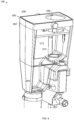
- FIG. 2 is an elevation view of an example implementation of the sprayer 108 of FIG. 1 including a spray containment system 200.
- FIG. 3 is a cross-sectional elevation view of the sprayer 108 and spray containment system 200 of FIG. 2 .
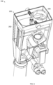
- FIG. 4 is a perspective view of the sprayer 108 and spray containment system 200 of FIG. 2 .
- FIG. 5 is another perspective view of the sprayer 108 and spray containment system 200 of FIG. 2 .
- the example spray containment system 200 of FIGS. 2-5 includes an enclosure 202.
- the enclosure 202 may be generally funnel-shaped, in that the enclosure 202 is configured to direct fluid toward a drain orifice 204 when in the upright position as illustrated in FIG. 2 .
- the drain orifice 204 may be connected to a drain pipe or other drainage conduit, or may be permitted to drain to a container or surface positioned below the drain orifice 204.
- the spray containment system 200 may be positioned such that the drain orifice 204 does not drain onto other components of the welding gun cleaning system 100.
- the drain orifice 204 is on a bottom side of the enclosure 202, which his opposite the top cover 206 of the enclosure 202.
- the top cover 206 may be a removable cover that blocks (e.g., obstructs, deflects, impedes) escape of anti-spatter fluid through a top side of the enclosure 202.
- the top cover 206 of the enclosure 202 includes a nozzle insertion orifice 208.
- the nozzle insertion orifice 208 enables insertion of the nozzle 104 of the welding gun 102 into the interior of the enclosure 202.
- the example enclosure 202 is dimensioned to receive at least the portion of the nozzle 104 that is to be sprayed with the anti-spatter fluid.
- a spray nozzle 210 of the anti-spatter fluid sprayer 108 is positioned within the enclosure 202 to spray the anti-spatter fluid toward a nozzle inserted into the nozzle insertion orifice 208.
- the nozzle 210 is positioned at a height between the top cover 206 and the bottom (e.g., the drain orifice 204) of the enclosure 202, and the enclosure 202 funnels or otherwise directs fluid from the location of the nozzle 210 toward the drain orifice 204.
- the example spray containment system 200 of FIGS. 2-5 further includes a baffle 212 positioned within an interior of the enclosure 202.
- the baffle 212 is configured to block at least a portion of the anti-spatter fluid sprayed from the spray nozzle 210 from exiting the enclosure 202 via the nozzle insertion orifice 208 in the top cover 206.
- the top cover 206 is blocks additional anti-spatter fluid that is not blocked by the baffle 212.
- the example baffle 212 is a plate that rests on ridges or other features within the enclosure 202, which may prevent movement of the baffle 212 upwards.
- the baffle 212 is positioned parallel to the top cover 206, and is secured with a dowel pressed into the bottom side of the top cover 206.
- the top cover 206 and the baffle 212 are easily removed for servicing or cleaning of the spray containment system 200.
- the baffle 212 has a nozzle insertion orifice 214 that is aligned with the nozzle insertion orifice of the top cover 206.
- the nozzle insertion orifices 208, 214 are not equipped or fitted with o-rings or seals.
- the baffle 212 is positioned within the enclosure 202 such that all, or substantially all, trajectories of the fluid from the spray nozzle 210 are blocked by the baffle 212, an inserted nozzle 104, or the enclosure 202 (including the top cover 206).
- any small amounts of escaping fluid have a low velocity and have a high likelihood of settling close to or on the spray containment system (e.g., instead of other equipment in the weld cell).
- the top cover 206 and/or the baffle 212 may be configured to have drain holes and/or gaps between the top cover 206 and/or the baffle 212 to promote drainage of anti-spatter fluid that settles on top of the baffle 212 or the top cover 206 to the drain orifice 204.
- spray containment system 200 may include multiple baffles.
- a second, third, and/or more baffles may be added in parallel to the baffle 212 (e.g., above or below the baffle 212) to further block anti-spatter fluid sprayed from the spray nozzle 210 from exiting the enclosure.
- "and/or” means any one or more of the items in the list joined by “and/or”.
- "x and/or y” means any element of the three-element set ⁇ (x), (y), (x, y) ⁇ . In other words, “x and/or y” means “one or both of x and y.”
- "x, y, and/or z” means any element of the seven-element set ⁇ (x), (y), (z), (x, y), (x, z), (y, z), (x, y, z) ⁇ . In other words, "x, y, and/or z” means “one or more of x, y and z”.
- circuitry is "operable" to perform a function whenever the circuitry comprises the necessary hardware and code (if any is necessary) to perform the function, regardless of whether performance of the function is disabled or not enabled (e.g., by an operator-configurable setting, factory trim, etc.).
Landscapes
- Engineering & Computer Science (AREA)
- Mechanical Engineering (AREA)
- Physics & Mathematics (AREA)
- Plasma & Fusion (AREA)
- Details Or Accessories Of Spraying Plant Or Apparatus (AREA)
Abstract
Description
- This disclosure relates generally to robotic welding and, more particularly, to spray containment systems and welding gun nozzle cleaning systems including spray containment systems.
- Welding guns may accumulate spatter or other contamination during welding operations. Welding gun nozzle cleaning systems may include reamers, anti-spatter sprayers, and/or lubricators, to improve the operational life of the welding gun nozzle.
- Spray containment systems and welding gun nozzle cleaning systems including spray containment systems are disclosed, substantially as illustrated by and described in connection with at least one of the figures, as set forth more completely in the claims.
-
-
FIG. 1 is a block diagram of an example welding gun cleaning system configured to clean a welding gun, in accordance with aspects of this disclosure. -
FIG. 2 is an elevation view of an example implementation of the sprayer ofFIG. 1 including a spray containment system. -
FIG. 3 is a cross-sectional elevation view of the sprayer and spray containment system ofFIG. 2 . -
FIG. 4 is a perspective view of the sprayer and spray containment system ofFIG. 2 . -
FIG. 5 is another perspective view of the sprayer and spray containment system ofFIG. 2 . - The figures are not necessarily to scale. Where appropriate, similar or identical reference numbers are used to refer to similar or identical components.
- For the purpose of promoting an understanding of the principles of this disclosure, reference will be now made to the examples illustrated in the drawings and specific language will be used to describe the same. It will nevertheless be understood that no limitation of the scope of the claims is intended by this disclosure. Modifications in the illustrated examples and such further applications of the principles of this disclosure as illustrated therein are contemplated as would typically occur to one skilled in the art to which this disclosure relates.
- Conventional anti-spatter fluid sprayers and spray containment systems sprayed anti-spatter fluid onto welding gun nozzles to slow the accumulation of spatter on the nozzle while reducing contamination of the weld cell by the sprayed anti-spatter fluid. Conventional sprayers and spray containment systems involved maintenance such as regular cleaning of the spray containment system to ensure performance of the spray system. Additionally, conventional spray containment systems may involve substantial manufacturing time and complexity to build.
- Disclosed example anti-spatter fluid sprayers and spray containment systems reduce the maintenance involved in using anti-spatter fluid on welding nozzle cleaning systems, reduce the complexity of the spray containment systems, and/or improve the effectiveness or performance of the spray containment system. Example anti-spatter fluid sprayers and spray containment systems include an enclosure, into which a welding gun nozzle may be inserted to be sprayed with anti-spatter fluid. Some disclosed example anti-spatter fluid sprayers and spray containment systems reduce overspray, or sprayed fluid escaping the spray containment system, by including both a top plate of an enclosure and an internal baffle positioned parallel with the top plate. Each of the top plate and the internal baffle have a concentric nozzle insertion orifice configured to permit insertion of the welding gun nozzle into the enclosure, but block all or nearly all anti-spatter fluid from escaping the enclosure through the top plate or nozzle insertion orifice. Anti-spatter fluid that is not deposited onto the welding gun nozzle is funneled toward a drain port opposite the top plate.
- Disclosed example anti-spatter fluid sprayers and spray containment systems provide a very low-maintenance solution to containing the overspray of anti-spatter spray, such as by substantially increasing the interval between maintenance compared with conventional spray containment devices. Disclosed example anti-spatter fluid sprayers and spray containment systems are also more robust and/or durable than conventional spray containment devices, such as by eliminating the use of o-rings at the point of nozzle insertion into the sprayer. Disclosed example anti-spatter fluid sprayers and spray containment systems may also be used with more types and/or sizes of welding nozzles than conventional spray containment devices (e.g., without having to change the size of the nozzle insertion orifice).
- Disclosed example anti-spatter coating systems include: an enclosure having a nozzle insertion orifice on a first side and a drain orifice on a second side of the enclosure; a spray nozzle configured to spray fluid toward a nozzle inserted into the nozzle insertion orifice, wherein the enclosure is configured to funnel the fluid in a direction toward the second side; and a baffle configured to block at least a first portion of sprayed fluid from the spray nozzle from exiting the enclosure via the nozzle insertion orifice, the first side configured to block at least a second portion of the sprayed fluid from the spray nozzle that is not blocked by the baffle.
- In some example anti-spatter coating systems, the first side of the enclosure faces upward. In some example anti-spatter coating systems, the baffle is positioned parallel to the first side. In some example anti-spatter coating systems, the baffle includes a second nozzle insertion orifice aligned with the nozzle insertion orifice of the enclosure.
- In some example anti-spatter coating systems, the baffle is internal to the enclosure. In some example anti-spatter coating systems, the spray nozzle is positioned between the first side and the second side of the enclosure. In some example anti-spatter coating systems, the enclosure includes a removable cover having the nozzle insertion orifice, in which the removable cover is removable from and replaceable onto the enclosure.
- In some example anti-spatter coating systems, the nozzle insertion orifice does not include a seal or o-ring. In some example anti-spatter coating systems, the baffle is positioned within the enclosure such that all direct trajectories of the fluid from the spray nozzle are blocked by at least one of the baffle, an inserted nozzle, or the enclosure.
- Disclosed example welding gun nozzle cleaning systems include: a reamer configured to remove spatter from a welding gun nozzle; and an anti-spatter coating system, including: an enclosure having a nozzle insertion orifice on a first side and a drain orifice on a second side of the enclosure, the nozzle insertion orifice configured to permit insertion of the welding gun nozzle through the nozzle insertion orifice; a spray nozzle configured to spray fluid toward a nozzle inserted into the nozzle insertion orifice, wherein the enclosure is configured to funnel the fluid in a direction toward the second side; and a baffle configured to block at least a first portion of sprayed fluid from the spray nozzle from exiting the enclosure via the nozzle insertion orifice, the first side configured to block at least a second portion of the sprayed fluid from the spray nozzle that is not blocked by the baffle.
- In some example welding gun nozzle cleaning systems, the first side of the enclosure faces upward. In some example welding gun nozzle cleaning systems, the baffle is positioned parallel to the first side. In some example welding gun nozzle cleaning systems, the baffle includes a second nozzle insertion orifice aligned with the nozzle insertion orifice of the enclosure.
- In some example welding gun nozzle cleaning systems, the baffle is internal to the enclosure. In some example welding gun nozzle cleaning systems, the spray nozzle is positioned between the first side and the second side of the enclosure. In some example welding gun nozzle cleaning systems, the enclosure includes a removable cover having the nozzle insertion orifice, the removable cover being removable from and replaceable onto the enclosure.
- In some example welding gun nozzle cleaning systems, the nozzle insertion orifice does not include a seal or o-ring. In some example welding gun nozzle cleaning systems, the baffle is positioned within the enclosure such that all direct trajectories of the fluid from the spray nozzle are blocked by at least one of the baffle, an inserted nozzle, or the enclosure.
- As used herein, the word "exemplary" means "serving as an example, instance, or illustration." The examples described herein are not limiting, but rather are exemplary only. It should be understood that the described examples are not necessarily to be construed as preferred or advantageous over other examples. Moreover, the terms "examples of the invention," "examples," or "invention" do not require that all examples of the invention include the discussed feature, advantage, or mode of operation.
- Disclosed example anti-spatter spray containment systems include: an enclosure having a nozzle insertion orifice on a first side and a drain orifice on a second side of the enclosure; a spray nozzle configured to spray fluid toward a nozzle inserted into the nozzle insertion orifice, wherein the enclosure is configured to funnel the fluid in a direction toward the second side; and a baffle configured to block at least a first portion of sprayed fluid from the spray nozzle from exiting the enclosure via the nozzle insertion orifice, the first side configured to block at least a second portion of the sprayed fluid from the spray nozzle that is not blocked by the baffle.
- In some examples, the first side of the enclosure faces upward. In some such examples, the baffle is positioned parallel to the first side. In some examples, the baffle includes a second nozzle insertion orifice aligned with the nozzle insertion orifice of the enclosure.
- In some example anti-spatter spray containment systems, the baffle is internal to the enclosure. In some example anti-spatter spray containment systems, the spray nozzle is positioned between the first side and the second side of the enclosure. In some example anti-spatter spray containment systems, the enclosure includes a removable cover having the nozzle insertion orifice, the removable cover being removable from and replaceable onto the enclosure.
- In some example anti-spatter spray containment systems, the nozzle insertion orifice does not include a seal or o-ring. In some example anti-spatter spray containment systems, the baffle is positioned within the enclosure such that all trajectories of the fluid from the spray nozzle are blocked by at least one of the baffle, an inserted nozzle, or the enclosure.
- Disclosed example welding gun nozzle cleaning systems include: a reamer having a nozzle cleaning bit configured to remove spatter from a welding gun nozzle; and an anti-spatter coating system having: an enclosure having a nozzle insertion orifice on a first side and a drain orifice on a second side of the enclosure, the nozzle insertion orifice configured to permit insertion of the welding gun nozzle through the nozzle insertion orifice; a spray nozzle configured to spray fluid toward a nozzle inserted into the nozzle insertion orifice, wherein the enclosure is configured to funnel the fluid in a direction toward the second side; and a baffle configured to block at least a first portion of sprayed fluid from the spray nozzle from exiting the enclosure via the nozzle insertion orifice, the first side configured to block at least a second portion of the sprayed fluid from the spray nozzle that is not blocked by the baffle.
-
FIG. 1 is a block diagram of an example weldinggun cleaning system 100 configured to clean awelding gun 102. Thewelding gun 102 may be manipulated by, for example, a robotic manipulator, a collaborative robot manipulator, or manually by a welding operator. Theexample welding gun 102 includes anozzle 104 which is generally subjected to spatter during welding operations, which can freeze and build up onto thenozzle 104, thereby reducing welding quality over time. - To remove spatter and/or reduce the adhesion of spatter on the welding nozzle, the example welding gun may be cleaned and/or conditioned by the welding
gun cleaning system 100. The example weldinggun cleaning system 100 includes anozzle reamer 106, an anti-spatterfluid sprayer 108 coupled to asprayer reservoir 110, and awire cutter 112. The example weldinggun cleaning system 100 may include additional accessories such as a motor lubricator, an air filter, an air regulator, and/or any other features. Thewelding gun 102 may be sequentially moved to positions to perform the configured gun cleaning operations. - The
example nozzle reamer 106 includes a motor and a bit (e.g., a blade or other cutting device), which mechanically removes spatter and/or other contaminants from the surface of thenozzle 104 and/or a contact tip or gas diffuser on thewelding gun 102. - The example anti-spatter
fluid sprayer 108 sprays or otherwise deposits an anti-spatter fluid onto the interior and/or exterior of thenozzle 104 and/or other portions of thewelding gun 102 that may be adversely affected by the buildup of spatter. Thesprayer 108 receives anti-spatter fluid stored in thesprayer reservoir 110. As discussed in more detail below, the anti-spatterfluid sprayer 108 is configured to reduce or prevent overspray, or the escape of anti-spatter fluid into the welding environment surrounding the weldinggun cleaning system 100. - The
wire cutter 112 is configured to cut an electrode wire sticking out from thewelding gun 102 to a consistent length and/or to have a consistent tip shape, which can improve arc starting. -
FIG. 2 is an elevation view of an example implementation of thesprayer 108 ofFIG. 1 including aspray containment system 200.FIG. 3 is a cross-sectional elevation view of thesprayer 108 andspray containment system 200 ofFIG. 2 .FIG. 4 is a perspective view of thesprayer 108 andspray containment system 200 ofFIG. 2 .FIG. 5 is another perspective view of thesprayer 108 andspray containment system 200 ofFIG. 2 . - The example
spray containment system 200 ofFIGS. 2-5 includes anenclosure 202. Theenclosure 202 may be generally funnel-shaped, in that theenclosure 202 is configured to direct fluid toward adrain orifice 204 when in the upright position as illustrated inFIG. 2 . Thedrain orifice 204 may be connected to a drain pipe or other drainage conduit, or may be permitted to drain to a container or surface positioned below thedrain orifice 204. In this regard, thespray containment system 200 may be positioned such that thedrain orifice 204 does not drain onto other components of the weldinggun cleaning system 100. - The
drain orifice 204 is on a bottom side of theenclosure 202, which his opposite thetop cover 206 of theenclosure 202. - The
top cover 206 may be a removable cover that blocks (e.g., obstructs, deflects, impedes) escape of anti-spatter fluid through a top side of theenclosure 202. Thetop cover 206 of theenclosure 202 includes anozzle insertion orifice 208. Thenozzle insertion orifice 208 enables insertion of thenozzle 104 of thewelding gun 102 into the interior of theenclosure 202. Theexample enclosure 202 is dimensioned to receive at least the portion of thenozzle 104 that is to be sprayed with the anti-spatter fluid. - A
spray nozzle 210 of the anti-spatterfluid sprayer 108 is positioned within theenclosure 202 to spray the anti-spatter fluid toward a nozzle inserted into thenozzle insertion orifice 208. In the example ofFIGS. 2-5 , thenozzle 210 is positioned at a height between thetop cover 206 and the bottom (e.g., the drain orifice 204) of theenclosure 202, and theenclosure 202 funnels or otherwise directs fluid from the location of thenozzle 210 toward thedrain orifice 204. - The example
spray containment system 200 ofFIGS. 2-5 further includes abaffle 212 positioned within an interior of theenclosure 202. Thebaffle 212 is configured to block at least a portion of the anti-spatter fluid sprayed from thespray nozzle 210 from exiting theenclosure 202 via thenozzle insertion orifice 208 in thetop cover 206. Thetop cover 206 is blocks additional anti-spatter fluid that is not blocked by thebaffle 212. - The
example baffle 212 is a plate that rests on ridges or other features within theenclosure 202, which may prevent movement of thebaffle 212 upwards. In the illustrated example, thebaffle 212 is positioned parallel to thetop cover 206, and is secured with a dowel pressed into the bottom side of thetop cover 206. Thetop cover 206 and thebaffle 212 are easily removed for servicing or cleaning of thespray containment system 200. Thebaffle 212 has anozzle insertion orifice 214 that is aligned with the nozzle insertion orifice of thetop cover 206. In the illustrated example, thenozzle insertion orifices baffle 212 is positioned within theenclosure 202 such that all, or substantially all, trajectories of the fluid from thespray nozzle 210 are blocked by thebaffle 212, an insertednozzle 104, or the enclosure 202 (including the top cover 206). While in some cases, small amounts of anti-spatter fluid (e.g., aerosolized particles or droplets entrained in airflow) manage to escape thespray containment system 200, thebaffle 212, thetop cover 206, and thespray nozzle 210 are positioned to consistently block or impede trajectories (e.g., direct, line-of-sight trajectories and/or bouncing trajectories) from thespray nozzle 210 to the exterior of thespray containment system 200. As a result, any small amounts of escaping fluid have a low velocity and have a high likelihood of settling close to or on the spray containment system (e.g., instead of other equipment in the weld cell). - In some examples, the
top cover 206 and/or thebaffle 212 may be configured to have drain holes and/or gaps between thetop cover 206 and/or thebaffle 212 to promote drainage of anti-spatter fluid that settles on top of thebaffle 212 or thetop cover 206 to thedrain orifice 204. - In some examples,
spray containment system 200 may include multiple baffles. For example, a second, third, and/or more baffles may be added in parallel to the baffle 212 (e.g., above or below the baffle 212) to further block anti-spatter fluid sprayed from thespray nozzle 210 from exiting the enclosure. - As utilized herein, "and/or" means any one or more of the items in the list joined by "and/or". As an example, "x and/or y" means any element of the three-element set {(x), (y), (x, y)}. In other words, "x and/or y" means "one or both of x and y." As another example, "x, y, and/or z" means any element of the seven-element set {(x), (y), (z), (x, y), (x, z), (y, z), (x, y, z)}. In other words, "x, y, and/or z" means "one or more of x, y and z". As utilized herein, the term "exemplary" means serving as a non-limiting example, instance, or illustration. As utilized herein, the terms "e.g." and "for example" set off lists of one or more non-limiting examples, instances, or illustrations. As utilized herein, circuitry is "operable" to perform a function whenever the circuitry comprises the necessary hardware and code (if any is necessary) to perform the function, regardless of whether performance of the function is disabled or not enabled (e.g., by an operator-configurable setting, factory trim, etc.).
- Certain embodiments of the invention are described in the following numbered clauses.
- Clause 1. An anti-spatter coating system, comprising:
- an enclosure having a nozzle insertion orifice on a first side and a drain orifice on a second side of the enclosure;
- a spray nozzle configured to spray fluid toward a nozzle inserted into the nozzle insertion orifice, wherein the enclosure is configured to funnel the fluid in a direction toward the second side; and
- a baffle configured to block at least a first portion of sprayed fluid from the spray nozzle from exiting the enclosure via the nozzle insertion orifice, the first side configured to block at least a second portion of the sprayed fluid from the spray nozzle that is not blocked by the baffle.
- Clause 2. The anti-spatter coating system as defined in clause 1, wherein the first side of the enclosure faces upward.
- Clause 3. The anti-spatter coating system as defined in clause 2, wherein the baffle is positioned parallel to the first side.
- Clause 4. The anti-spatter coating system as defined in clause 3, wherein the baffle comprises a second nozzle insertion orifice aligned with the nozzle insertion orifice of the enclosure.
- Clause 5. The anti-spatter coating system as defined in clause 1, wherein the baffle is internal to the enclosure.
- Clause 6. The anti-spatter coating system as defined in clause 1, wherein the spray nozzle is positioned between the first side and the second side of the enclosure.
- Clause 7. The anti-spatter coating system as defined in clause 1, wherein the enclosure comprises a removable cover having the nozzle insertion orifice, the removable cover being removable from and replaceable onto the enclosure.
- Clause 8. The anti-spatter coating system as defined in clause 1, wherein the nozzle insertion orifice does not include a seal or o-ring.
- Clause 9. The anti-spatter coating system as defined in clause 1, wherein the baffle is positioned within the enclosure such that all direct trajectories of the fluid from the spray nozzle are blocked by at least one of the baffle, an inserted nozzle, or the enclosure.
- Clause 10. A welding gun nozzle cleaning system, comprising:
- a reamer configured to remove spatter from a welding gun nozzle; and
- an anti-spatter coating system comprising:
- an enclosure having a nozzle insertion orifice on a first side and a drain orifice on a second side of the enclosure, the nozzle insertion orifice configured to permit insertion of the welding gun nozzle through the nozzle insertion orifice;
- a spray nozzle configured to spray fluid toward a nozzle inserted into the nozzle insertion orifice, wherein the enclosure is configured to funnel the fluid in a direction toward the second side; and
- a baffle configured to block at least a first portion of sprayed fluid from the spray nozzle from exiting the enclosure via the nozzle insertion orifice, the first side configured to block at least a second portion of the sprayed fluid from the spray nozzle that is not blocked by the baffle.
- Clause 11. The welding gun nozzle cleaning system as defined in clause 10, wherein the first side of the enclosure faces upward.
- Clause 12. The welding gun nozzle cleaning system as defined in clause 11, wherein the baffle is positioned parallel to the first side.
- Clause 13. The welding gun nozzle cleaning system as defined in clause 12, wherein the baffle comprises a second nozzle insertion orifice aligned with the nozzle insertion orifice of the enclosure.
- Clause 14. The welding gun nozzle cleaning system as defined in clause 10, wherein the baffle is internal to the enclosure.
- Clause 15. The welding gun nozzle cleaning system as defined in clause 10, wherein the spray nozzle is positioned between the first side and the second side of the enclosure.
- Clause 16. The welding gun nozzle cleaning system as defined in clause 10, wherein the enclosure comprises a removable cover having the nozzle insertion orifice, the removable cover being removable from and replaceable onto the enclosure.
- Clause 17. The welding gun nozzle cleaning system as defined in clause 10, wherein the nozzle insertion orifice does not include a seal or o-ring.
- Clause 18. The welding gun nozzle cleaning system as defined in clause 10, wherein the baffle is positioned within the enclosure such that all direct trajectories of the fluid from the spray nozzle are blocked by at least one of the baffle, an inserted nozzle, or the enclosure.
- While the present method and/or system has been described with reference to certain implementations, it will be understood by those skilled in the art that various changes may be made and equivalents may be substituted without departing from the scope of the present method and/or system. In addition, many modifications may be made to adapt a particular situation or material to the teachings of the present disclosure without departing from its scope. For example, block and/or components of disclosed examples may be combined, divided, re-arranged, and/or otherwise modified. Therefore, the present method and/or system are not limited to the particular implementations disclosed. Instead, the present method and/or system will include all implementations falling within the scope of the appended claims, both literally and under the doctrine of equivalents.
Claims (14)
- An anti-spatter coating system, comprising:an enclosure having a nozzle insertion orifice on a first side and a drain orifice on a second side of the enclosure;a spray nozzle configured to spray fluid toward a nozzle inserted into the nozzle insertion orifice, wherein the enclosure is configured to funnel the fluid in a direction toward the second side; anda baffle configured to block at least a first portion of sprayed fluid from the spray nozzle from exiting the enclosure via the nozzle insertion orifice, the first side configured to block at least a second portion of the sprayed fluid from the spray nozzle that is not blocked by the baffle.
- The anti-spatter coating system as defined in claim 1, wherein the first side of the enclosure faces upward and optionallywherein the baffle is positioned parallel to the first side and optionallywherein the baffle comprises a second nozzle insertion orifice aligned with the nozzle insertion orifice of the enclosure.
- The anti-spatter coating system as defined in claim 1, wherein the baffle is internal to the enclosure.
- The anti-spatter coating system as defined in claim 1, wherein the spray nozzle is positioned between the first side and the second side of the enclosure.
- The anti-spatter coating system as defined in claim 1, wherein the enclosure comprises a removable cover having the nozzle insertion orifice, the removable cover being removable from and replaceable onto the enclosure.
- The anti-spatter coating system as defined in claim 1, wherein the nozzle insertion orifice does not include a seal or o-ring.
- The anti-spatter coating system as defined in claim 1, wherein the baffle is positioned within the enclosure such that all direct trajectories of the fluid from the spray nozzle are blocked by at least one of the baffle, an inserted nozzle, or the enclosure.
- A welding gun nozzle cleaning system, comprising:a reamer configured to remove spatter from a welding gun nozzle; andan anti-spatter coating system comprising:an enclosure having a nozzle insertion orifice on a first side and a drain orifice on a second side of the enclosure, the nozzle insertion orifice configured to permit insertion of the welding gun nozzle through the nozzle insertion orifice;a spray nozzle configured to spray fluid toward a nozzle inserted into the nozzle insertion orifice, wherein the enclosure is configured to funnel the fluid in a direction toward the second side; anda baffle configured to block at least a first portion of sprayed fluid from the spray nozzle from exiting the enclosure via the nozzle insertion orifice, the first side configured to block at least a second portion of the sprayed fluid from the spray nozzle that is not blocked by the baffle.
- The welding gun nozzle cleaning system as defined in claim 8, wherein the first side of the enclosure faces upward and optionallywherein the baffle is positioned parallel to the first side and optionallywherein the baffle comprises a second nozzle insertion orifice aligned with the nozzle insertion orifice of the enclosure.
- The welding gun nozzle cleaning system as defined in claim 8, wherein the baffle is internal to the enclosure.
- The welding gun nozzle cleaning system as defined in claim 8, wherein the spray nozzle is positioned between the first side and the second side of the enclosure.
- The welding gun nozzle cleaning system as defined in claim 8, wherein the enclosure comprises a removable cover having the nozzle insertion orifice, the removable cover being removable from and replaceable onto the enclosure.
- The welding gun nozzle cleaning system as defined in claim 8, wherein the nozzle insertion orifice does not include a seal or o-ring.
- The welding gun nozzle cleaning system as defined in claim 8, wherein the baffle is positioned within the enclosure such that all direct trajectories of the fluid from the spray nozzle are blocked by at least one of the baffle, an inserted nozzle, or the enclosure.
Applications Claiming Priority (2)
| Application Number | Priority Date | Filing Date | Title |
|---|---|---|---|
| US202163237724P | 2021-08-27 | 2021-08-27 | |
| US17/889,915 US12162105B2 (en) | 2021-08-27 | 2022-08-17 | Spray containment systems and welding gun nozzle cleaning systems including spray containment systems |
Publications (1)
| Publication Number | Publication Date |
|---|---|
| EP4140606A1 true EP4140606A1 (en) | 2023-03-01 |
Family
ID=83006026
Family Applications (1)
| Application Number | Title | Priority Date | Filing Date |
|---|---|---|---|
| EP22191440.1A Pending EP4140606A1 (en) | 2021-08-27 | 2022-08-22 | Spray containment systems and welding gun nozzle cleaning systems including spray containment systems |
Country Status (4)
| Country | Link |
|---|---|
| US (1) | US12162105B2 (en) |
| EP (1) | EP4140606A1 (en) |
| CN (1) | CN115722496A (en) |
| CA (1) | CA3170788A1 (en) |
Citations (5)
| Publication number | Priority date | Publication date | Assignee | Title |
|---|---|---|---|---|
| US5387376A (en) * | 1991-01-17 | 1995-02-07 | Galipag | Process and apparatus for mass transfer between liquid and gaseous media |
| JPH07314142A (en) * | 1994-05-25 | 1995-12-05 | Chiyoda Kogyo Kk | Nozzle cleaning method of arc welding torch |
| US6578590B2 (en) * | 2001-03-21 | 2003-06-17 | Danny Leblond | Rotative cleaning and sanitizing device |
| US20060249498A1 (en) * | 2003-04-28 | 2006-11-09 | Ralf Schaefer | Device for cleaning the gas nozzle of a welding torch |
| JP2013180337A (en) * | 2012-03-02 | 2013-09-12 | Tipman Co Ltd | Device for applying sputter adhesion preventing fluid |
Family Cites Families (9)
| Publication number | Priority date | Publication date | Assignee | Title |
|---|---|---|---|---|
| DE3421885C2 (en) * | 1984-06-13 | 1986-10-23 | Thielmann, Friedolin | Process for cleaning the gas nozzle of a welding torch and device for carrying out the process |
| US6418944B1 (en) * | 1996-11-18 | 2002-07-16 | Kevin R. White | Method and apparatus for cleaning spray guns |
| US6034351A (en) * | 1998-06-24 | 2000-03-07 | Sato; Katsuhiro | Cleaning apparatus for welding torch nozzle and method of cleaning the same |
| CA2391149A1 (en) | 2001-06-21 | 2002-12-21 | Intertech Systems, Inc. | A cleaning system for welding torches which effects cleaning by means of cold temperature |
| DE20216788U1 (en) * | 2002-10-31 | 2003-03-13 | Fronius International Gmbh, Pettenbach | Device for cleaning welding torches |
| CN103949760B (en) * | 2014-05-14 | 2016-04-06 | 泰佰亿(山东)工业有限公司 | Sensing welding spray device |
| DE102015001246B3 (en) * | 2015-01-31 | 2016-06-16 | Audi Ag | Cleaning device for a mechanical cleaning of a gas nozzle of a protective gas welding torch |
| CN209664634U (en) * | 2019-01-03 | 2019-11-22 | 广州李尔汽车部件有限公司 | Welding gun automatic oil removing device |
| CN212790657U (en) * | 2020-07-07 | 2021-03-26 | 广州市采奴化妆品有限公司 | Prevent shampoo agitating unit that splashes |
-
2022
- 2022-08-17 US US17/889,915 patent/US12162105B2/en active Active
- 2022-08-19 CA CA3170788A patent/CA3170788A1/en active Pending
- 2022-08-22 EP EP22191440.1A patent/EP4140606A1/en active Pending
- 2022-08-25 CN CN202211027129.2A patent/CN115722496A/en active Pending
Patent Citations (5)
| Publication number | Priority date | Publication date | Assignee | Title |
|---|---|---|---|---|
| US5387376A (en) * | 1991-01-17 | 1995-02-07 | Galipag | Process and apparatus for mass transfer between liquid and gaseous media |
| JPH07314142A (en) * | 1994-05-25 | 1995-12-05 | Chiyoda Kogyo Kk | Nozzle cleaning method of arc welding torch |
| US6578590B2 (en) * | 2001-03-21 | 2003-06-17 | Danny Leblond | Rotative cleaning and sanitizing device |
| US20060249498A1 (en) * | 2003-04-28 | 2006-11-09 | Ralf Schaefer | Device for cleaning the gas nozzle of a welding torch |
| JP2013180337A (en) * | 2012-03-02 | 2013-09-12 | Tipman Co Ltd | Device for applying sputter adhesion preventing fluid |
Also Published As
| Publication number | Publication date |
|---|---|
| US12162105B2 (en) | 2024-12-10 |
| CN115722496A (en) | 2023-03-03 |
| US20230061447A1 (en) | 2023-03-02 |
| CA3170788A1 (en) | 2023-02-27 |
Similar Documents
| Publication | Publication Date | Title |
|---|---|---|
| US5487695A (en) | Blast nozzle combined with multiple tip water atomizer | |
| EP0578426B1 (en) | Improvements in and relating to powder coating | |
| CN103464328B (en) | Coating cloud segregation apparatuss | |
| CN100528375C (en) | Paint spraying equipment with air purification device | |
| US7321104B2 (en) | Cooling duct of a laser processing machine | |
| CN105562383A (en) | Cleaning process and cleaning device for one or more parts of an application system | |
| US12162105B2 (en) | Spray containment systems and welding gun nozzle cleaning systems including spray containment systems | |
| US7334742B2 (en) | Spraying device with droplet hold-back | |
| DE102015016674A1 (en) | Device and method for protecting a laser optics | |
| DK157289B (en) | METHOD AND APPARATUS FOR POLLUTING AIR POLLUTION | |
| US4344381A (en) | Apparatus for continuously electrostatically coating an elongated object | |
| US4768533A (en) | Paint and varnish stripping system | |
| US4089295A (en) | Spray coater device | |
| CN108067700B (en) | Iron tip cleaner for soldering iron | |
| CN117943233A (en) | Painting robot with paint mist recovery and working method thereof | |
| JP2818648B2 (en) | Weld fume recovery equipment | |
| JP3438080B2 (en) | Method and apparatus for preventing contamination of deflection distribution nozzle device | |
| JP2898821B2 (en) | Weld fume recovery equipment | |
| EP1469948B1 (en) | Device for removing and sucking powders externally of one or more powder-drawing pipes | |
| JPH0494875A (en) | Device for cleaning spatter and applying spatter sticking preventive for welding nozzle | |
| KR200270975Y1 (en) | Laser Welding Gas Purification Apparatus of Metal Parts | |
| US20240424741A1 (en) | Cleaning apparatus | |
| JP4537185B2 (en) | Painting system | |
| KR20260018784A (en) | Systems and methods for coating surfaces | |
| CN121794091A (en) | Splash adhesion suppressing device for laser processing machine, laser processing machine and laser processing method |
Legal Events
| Date | Code | Title | Description |
|---|---|---|---|
| PUAI | Public reference made under article 153(3) epc to a published international application that has entered the european phase |
Free format text: ORIGINAL CODE: 0009012 |
|
| STAA | Information on the status of an ep patent application or granted ep patent |
Free format text: STATUS: THE APPLICATION HAS BEEN PUBLISHED |
|
| AK | Designated contracting states |
Kind code of ref document: A1 Designated state(s): AL AT BE BG CH CY CZ DE DK EE ES FI FR GB GR HR HU IE IS IT LI LT LU LV MC MK MT NL NO PL PT RO RS SE SI SK SM TR |
|
| STAA | Information on the status of an ep patent application or granted ep patent |
Free format text: STATUS: REQUEST FOR EXAMINATION WAS MADE |
|
| 17P | Request for examination filed |
Effective date: 20230808 |
|
| RBV | Designated contracting states (corrected) |
Designated state(s): AL AT BE BG CH CY CZ DE DK EE ES FI FR GB GR HR HU IE IS IT LI LT LU LV MC MK MT NL NO PL PT RO RS SE SI SK SM TR |
|
| STAA | Information on the status of an ep patent application or granted ep patent |
Free format text: STATUS: EXAMINATION IS IN PROGRESS |
|
| 17Q | First examination report despatched |
Effective date: 20231220 |
|
| RIC1 | Information provided on ipc code assigned before grant |
Ipc: B23K 9/32 20060101ALI20250515BHEP Ipc: B08B 17/06 20060101ALI20250515BHEP Ipc: B08B 17/02 20060101ALI20250515BHEP Ipc: B08B 3/02 20060101ALI20250515BHEP Ipc: B08B 1/16 20240101ALI20250515BHEP Ipc: B08B 1/00 20060101AFI20250515BHEP |