EP4140519B1 - Anschluss eines intravenösen schlauches, system und ladeverfahren - Google Patents
Anschluss eines intravenösen schlauches, system und ladeverfahren Download PDFInfo
- Publication number
- EP4140519B1 EP4140519B1 EP22193186.8A EP22193186A EP4140519B1 EP 4140519 B1 EP4140519 B1 EP 4140519B1 EP 22193186 A EP22193186 A EP 22193186A EP 4140519 B1 EP4140519 B1 EP 4140519B1
- Authority
- EP
- European Patent Office
- Prior art keywords
- tubing
- mating recess
- delivery device
- fluid delivery
- fitment
- Prior art date
- Legal status (The legal status is an assumption and is not a legal conclusion. Google has not performed a legal analysis and makes no representation as to the accuracy of the status listed.)
- Active
Links
Images






Classifications
-
- A—HUMAN NECESSITIES
- A61—MEDICAL OR VETERINARY SCIENCE; HYGIENE
- A61M—DEVICES FOR INTRODUCING MEDIA INTO, OR ONTO, THE BODY; DEVICES FOR TRANSDUCING BODY MEDIA OR FOR TAKING MEDIA FROM THE BODY; DEVICES FOR PRODUCING OR ENDING SLEEP OR STUPOR
- A61M39/00—Tubes, tube connectors, tube couplings, valves, access sites or the like, specially adapted for medical use
- A61M39/08—Tubes; Storage means specially adapted therefor
-
- A—HUMAN NECESSITIES
- A61—MEDICAL OR VETERINARY SCIENCE; HYGIENE
- A61M—DEVICES FOR INTRODUCING MEDIA INTO, OR ONTO, THE BODY; DEVICES FOR TRANSDUCING BODY MEDIA OR FOR TAKING MEDIA FROM THE BODY; DEVICES FOR PRODUCING OR ENDING SLEEP OR STUPOR
- A61M39/00—Tubes, tube connectors, tube couplings, valves, access sites or the like, specially adapted for medical use
- A61M39/10—Tube connectors; Tube couplings
-
- A—HUMAN NECESSITIES
- A61—MEDICAL OR VETERINARY SCIENCE; HYGIENE
- A61M—DEVICES FOR INTRODUCING MEDIA INTO, OR ONTO, THE BODY; DEVICES FOR TRANSDUCING BODY MEDIA OR FOR TAKING MEDIA FROM THE BODY; DEVICES FOR PRODUCING OR ENDING SLEEP OR STUPOR
- A61M5/00—Devices for bringing media into the body in a subcutaneous, intra-vascular or intramuscular way; Accessories therefor, e.g. filling or cleaning devices, arm-rests
- A61M5/14—Infusion devices, e.g. infusing by gravity; Blood infusion; Accessories therefor
- A61M5/1413—Modular systems comprising interconnecting elements
-
- A—HUMAN NECESSITIES
- A61—MEDICAL OR VETERINARY SCIENCE; HYGIENE
- A61M—DEVICES FOR INTRODUCING MEDIA INTO, OR ONTO, THE BODY; DEVICES FOR TRANSDUCING BODY MEDIA OR FOR TAKING MEDIA FROM THE BODY; DEVICES FOR PRODUCING OR ENDING SLEEP OR STUPOR
- A61M5/00—Devices for bringing media into the body in a subcutaneous, intra-vascular or intramuscular way; Accessories therefor, e.g. filling or cleaning devices, arm-rests
- A61M5/14—Infusion devices, e.g. infusing by gravity; Blood infusion; Accessories therefor
- A61M5/142—Pressure infusion, e.g. using pumps
- A61M5/14212—Pumping with an aspiration and an expulsion action
- A61M5/14228—Pumping with an aspiration and an expulsion action with linear peristaltic action, i.e. comprising at least three pressurising members or a helical member
-
- A—HUMAN NECESSITIES
- A61—MEDICAL OR VETERINARY SCIENCE; HYGIENE
- A61M—DEVICES FOR INTRODUCING MEDIA INTO, OR ONTO, THE BODY; DEVICES FOR TRANSDUCING BODY MEDIA OR FOR TAKING MEDIA FROM THE BODY; DEVICES FOR PRODUCING OR ENDING SLEEP OR STUPOR
- A61M39/00—Tubes, tube connectors, tube couplings, valves, access sites or the like, specially adapted for medical use
- A61M39/08—Tubes; Storage means specially adapted therefor
- A61M2039/087—Tools for handling tubes, e.g. crimping tool for connecting tubes to a connector
-
- A—HUMAN NECESSITIES
- A61—MEDICAL OR VETERINARY SCIENCE; HYGIENE
- A61M—DEVICES FOR INTRODUCING MEDIA INTO, OR ONTO, THE BODY; DEVICES FOR TRANSDUCING BODY MEDIA OR FOR TAKING MEDIA FROM THE BODY; DEVICES FOR PRODUCING OR ENDING SLEEP OR STUPOR
- A61M2205/00—General characteristics of the apparatus
- A61M2205/33—Controlling, regulating or measuring
- A61M2205/3331—Pressure; Flow
- A61M2205/3355—Controlling downstream pump pressure
-
- A—HUMAN NECESSITIES
- A61—MEDICAL OR VETERINARY SCIENCE; HYGIENE
- A61M—DEVICES FOR INTRODUCING MEDIA INTO, OR ONTO, THE BODY; DEVICES FOR TRANSDUCING BODY MEDIA OR FOR TAKING MEDIA FROM THE BODY; DEVICES FOR PRODUCING OR ENDING SLEEP OR STUPOR
- A61M2205/00—General characteristics of the apparatus
- A61M2205/60—General characteristics of the apparatus with identification means
- A61M2205/6045—General characteristics of the apparatus with identification means having complementary physical shapes for indexing or registration purposes
-
- A—HUMAN NECESSITIES
- A61—MEDICAL OR VETERINARY SCIENCE; HYGIENE
- A61M—DEVICES FOR INTRODUCING MEDIA INTO, OR ONTO, THE BODY; DEVICES FOR TRANSDUCING BODY MEDIA OR FOR TAKING MEDIA FROM THE BODY; DEVICES FOR PRODUCING OR ENDING SLEEP OR STUPOR
- A61M2205/00—General characteristics of the apparatus
- A61M2205/60—General characteristics of the apparatus with identification means
- A61M2205/6063—Optical identification systems
-
- A—HUMAN NECESSITIES
- A61—MEDICAL OR VETERINARY SCIENCE; HYGIENE
- A61M—DEVICES FOR INTRODUCING MEDIA INTO, OR ONTO, THE BODY; DEVICES FOR TRANSDUCING BODY MEDIA OR FOR TAKING MEDIA FROM THE BODY; DEVICES FOR PRODUCING OR ENDING SLEEP OR STUPOR
- A61M2205/00—General characteristics of the apparatus
- A61M2205/60—General characteristics of the apparatus with identification means
- A61M2205/6063—Optical identification systems
- A61M2205/6081—Colour codes
Definitions
- the present disclosure generally relates to an intravenous (IV) set or infusion pump flow control, and in particular an IV tubing fitment for securing an IV tube to a fluid delivery device.
- IV intravenous
- US 11 045 599 B2 relates to connectors which are intended for use in the medical field such as in perfusion devices for intravenous or arterial catheters, and discloses a an intravenous, IV, tubing fitment, comprising: a fluid delivery device including a body forming, in part, a mating recess and a door, wherein the door forms part of the mating recess, and an intravenous, IV, tubing fitment, comprising a unitary body configured to couple with the mating recess of the fluid delivery device.
- IV sets are loaded into a medical device, such as an infusion pump, that controls the flow rate through the tubing. Due to the designs of existing IV sets, the IV sets can be unintentionally misloaded causing the tubing of the IV sets to be pulled, twisted, entangled, or otherwise interfered with. IV sets that are misloaded result in portions of the tubing to be reshaped, which in turn causes a change or occludes a flow rate produced by the medical device. For example, IV set that are misloaded can be pulled causing the tubing to stretch and narrow a diameter of the tubing. Misloaded IV sets can result in inaccurate flow rates, uncontrolled flow rates, over infusion, under infusion, and/or a number of other issues.
- the invention is related to an intravenous tubing fitment, a system and a method for loading an intravenous set to a fluid delivery device as set out in the appended set of claims.
- Various implementations of systems, methods, and devices within the scope of the appended claims each have several aspects, no single one of which is solely responsible for the attributes described herein. Without limiting the scope of the appended claims, after considering this disclosure, and particularly after considering the section entitled “Detailed Description" one will understand how the aspects of some implementations are used to prevent an IV set from being misloaded to provide accurate and consistent flow rates.
- One or more implementations provide an IV tubing fitment including a unitary body that is configured to be received by a pocket of a fluid delivery device in a single configuration.
- the IV tubing fitment is configured such that the fluid delivery device is unable to use the IV tubing fitment if misloaded. More specifically, the IV tubing fitment is designed such that a fluid delivery device cannot be forced closed if the IV tubing fitment is misloaded. By not allowing itself to be misloaded, the IV tubing fitment prevents a tubing of the IV set from being excessively pulled, stretched, entangled, kinked, etc. by securely holding the IV set in place within the fluid delivery device. Thus, the IV tubing fitment prevents the diameter, wall thickness, or length of the tubing of the IV set from being altered. The IV tubing fitment further allows the tubing of the IV set to rotate about a longitudinal axis while held in place within the fluid delivery device.
- an intravenous (IV) tubing fitment includes a unitary body.
- the unitary body includes a first end configured to couple to a first portion of a tubing, a substantially hemispherical surface adjacent to the first end, and a cylindrical body adjacent to the substantially hemispherical surface.
- the cylindrical body including a plurality of wings and is configured to receive a second portion of the tubing.
- the unitary body is configured to be received into a mating recess of a fluid delivery device such that the substantially hemispherical surface is uniformly mated with a substantially identical surface of the mating recess, and the cylindrical body is positioned outside of the mating recess.
- the unitary body is molded.
- the fluid delivery device is an infusion pump.
- the unitary body when received by the mating recess, rotates about a longitudinal axis at least 270 degrees in a clockwise and counterclockwise direction. In some implementations, the unitary body rotates about the longitudinal axis a full 360 degrees in each direction.
- the substantially hemispherical surface includes an outer rim that is configured to engage with a door of the fluid delivery device.
- the outer rim when engaged with the door of the fluid delivery device, restricts movement of the unitary body, in at least one of a longitudinal and a latitudinal directions.
- the substantially hemispherical surface is uniformly mated with the substantially identical surface of the mating recess only when the first end of the unitary body is received within a pocket of the mating recess preventing the IV tubing fitment from being misloaded. In some implementations, when the first end of the unitary body is received within the pocket of the mating recess, the first portion of the tubing coupled with the first end of the unitary body is aligned along a center of the mating recess.
- the substantially hemispherical surface has a diameter that is substantially equal to a diameter of the mating recess, the diameter of the substantially hemispherical surface preventing the fluid delivery device from closing when the substantially hemispherical surface is not uniformly mated with the substantially identical surface of the mating recess.
- a system for loading an intravenous (IV) set includes an IV tubing fitment and a fluid delivery device.
- the fluid delivery device includes a body forming, in part, a mating recess and a door forming another part of the mating recess. While the door is in an open position, the mating recess is configured to receive the IV tubing fitment such that the mating recess is uniformly mated with a substantially hemispherical surface of the IV tubing fitment, and a portion of the IV tubing fitment is positioned outside of the body of the fluid delivery device.
- the door When the door is moved to a closed position while the IV tubing fitment is mated with the mating recess, the door is configured to couple with the body of the fluid delivery device enclosing the IV tubing fitment in a pocket.
- the door includes one or more coupling members configured to couple to a portion of the IV tubing fitment (e.g., an outer rim of the uniform body).
- the door is prevented from coupling with the body of the fluid delivery device while at least a portion of the IV tubing fitment is misloaded.
- a method for loading an intravenous (IV) set to a fluid delivery device is provided.
- the method is performed at a fluid delivery device including a body forming, in part, a mating recess and a door forming another part of the mating recess.
- the method includes while the door is in an open position, receiving an IV tubing fitment at the mating recess such that a substantially hemispherical surface of the IV tubing fitment is uniformly mated with a substantially identical surface of the mating recess.
- the method further includes closing the door such that the door couples with the body of the fluid delivery device and forms an enclosure that is configured to surround at least a portion of the IV tubing fitment.
- the disclosed IV tubing fitment secures an IV set to fluid delivery device such that a tubing of the IV set cannot be damaged or altered by misloading of the IV set.
- the IV tubing fitment includes an intuitive design that allows users to readily recognize an orientation in which the IV tubing fitment should be placed within a fluid delivery device to ensure that the IV set is properly loaded. Further, the IV tubing fitment is designed such that the fluid delivery device is unable to close while the IV tubing fitment is misloaded.
- the IV tubing fitment reduces the chances of the IV set being damaged by being forced into a fluid delivery device thereby improving the accuracy and consistency of the flow rate generated by the fluid delivery device.
- the detailed description set forth below is intended as a description of various configurations of the subject technology and is not intended to represent the only configurations in which the subject technology may be practiced. The detailed description includes specific details for the purpose of providing a thorough understanding of the subject technology. However, it will be apparent to those skilled in the art that the subject technology may be practiced without these specific details. In some instances, well-known structures and components are shown in block diagram form in order to avoid obscuring the concepts of the subject technology. Like components are labeled with identical element numbers for ease of understanding. Reference numbers may have letter suffixes appended to indicate separate instances of a common element while being referred to generically by the same number without a suffix letter.
- the disclosed IV tubing fitment overcome several challenges discovered with respect to certain conventional IV sets.
- One challenge with certain conventional IV sets is the misloading of IV sets that can cause damage to a tube of the IV sets resulting in inaccurate, inconsistent, and uncontrollable flow rates. Because of the inaccuracies or the inconsistencies of caused by misloaded IV sets, thereby potentially harming the patient or decreasing the efficacy of a treatment, the use of conventional IV sets afford limited protection from adverse conditions due to misloading.
- an IV tubing fitment as described herein that eliminates or substantially reduces the possibility of misloading IV sets.
- the disclosed IV tubing fitment securely holds an IV set in place and also prevents a fluid delivery device from receiving an IV set if misloaded thereby improving the accuracy and consistency of a generated flow rate.
- FIG. 1 shows a patient care system, in accordance with various aspects of the present disclosure.
- the patient care system 20 includes four infusion pumps 22, 24, 26, and 28 each of which is fluidly connected with an upstream fluid line 30, 32, 34, and 36, respectively.
- Each fluid line 30, 32, 34, and 36 is held in place at a respective infusion pumps 22, 24, 26, and 28 via a respective IV tubing fitment (e.g., IV tubing fitment 54; Figure 2 ).
- Each of the four infusion pumps 22, 24, 26, and 28 is also fluidly connected with a downstream fluid line 31, 33, 35, and 37, respectively.
- the fluid lines can be any type of fluid conduit, such as an IV administration set, through which fluid can flow through. It should be appreciated that any of a variety of pump mechanisms can be used including syringe pumps.
- Fluid supplies 38, 40, 42, and 44 which may take various forms but in this case are shown as bottles, are inverted and suspended above the pumps. Fluid supplies may also take the form of bags or other types of containers including syringes. Both the patient care system 20 and the fluid supplies 38, 40, 42, and 44 are mounted to a roller stand, IV pole 46, tabletop, etc.
- a separate infusion pump 22, 24, 26, and 28 is used to infuse each of the fluids of the fluid supplies into the patient.
- the infusion pumps are flow control devices that will act on the respective fluid line to move the fluid from the fluid supply through the fluid line to the patient 48. Because individual pumps are used, each can be individually set to the pumping or operating parameters required for infusing the particular medical fluid from the respective fluid supply into the patient at the particular rate prescribed for that fluid by the physician. Such medical fluids may include drugs or nutrients or other fluids.
- the infusion pumps 22, 24, 26, and 28 are controlled by a controller 60. In some implementations, the controller 60 is communicatively coupled to memory storing one or more instructions for operating the infusion pumps 22, 24, 26, and 28 and/or other collected data as described below.
- Fluid supplies 38, 40, 42, and 44 are each coupled to an electronic data tag 81, 83, 85, and 87, respectively, or to an electronic transmitter. Any device or component associated with the infusion system may be equipped with an electronic data tag, reader, or transmitter.
- an infusion pump 22 having a body 27 is shown in perspective view, in accordance with various aspects of the present disclosure.
- the infusion pump 22 is shown with the front door 50 open, showing the upstream fluid line 30 and downstream fluid line 31 in operative engagement with the infusion pump 22. More specifically, the fluid line 30 is coupled to (or received by) an IV tubing fitment 54 that is held in place within a pocket and/or mating recess of the infusion pump 22.
- the IV tubing fitment 54 is a unitary body including a first end configured to couple to a first portion of a tubing (e.g., tube 66) and a second end opposite the first end coupled to (or configured to receive) a second portion of the tubing (e.g., fluid line 30).
- the IV tubing fitment 54 includes a substantially hemispherical surface that, when received by the infusion pump 22, is uniformly mated with a substantially identical surface of the mating recess of the infusion pump 22. Additional information on the placement of the IV tubing fitment 54 is provided below in reference to Figures 6A-6D .
- the IV tubing fitment 54 reduces the chances of an IV set (e.g., at least the upstream fluid line 30, the tube 66, and the downstream fluid line 31) from being misloaded by preventing the door 50 of the infusion pump 22 from closing if the substantially hemispherical surface of the IV tubing fitment 54 is not mated to the mating recess of the infusion pump 22.
- a diameter of the substantially hemispherical surface of the IV tubing fitment 54 is such that the door 50 cannot be closed unless the IV tubing fitment 54 is in the correct position (i.e., the substantially hemispherical surface of the IV tubing fitment 54 is mated to the mating recess).
- the substantially hemispherical surface of the IV tubing fitment 54 has a diameter that is substantially equal to a diameter of the mating recess of the infusion pump 22.
- the diameter of the substantially hemispherical surface of the IV tubing fitment 54 prevents the infusion pump 22 from closing when the substantially hemispherical surface of the IV tubing fitment 54 is not uniformly mated with the substantially identical surface of the mating recess of the infusion pump 22.
- a hook on the door 50 latching arm 52 will not engage the latch hook unless the IV tubing fitment 54 is in the correct position.
- the IV tubing fitment 54 prevents a user from forcing the latch to close the door 50 and applying a forced leverage, which can cause damage to the IV set, the door hinges, or breakage of the platen.
- the IV tubing fitment 54 allows the IV set to rotate about its longitudinal axis (e.g., center line of the upstream fluid line 30) while preventing the IV set from twisting, kinking, and/or entangling.
- the IV tubing fitment 54 rotates about a longitudinal axis at least 270 degrees in a clockwise and counterclockwise direction.
- the IV tubing fitment 54 rotates about the longitudinal axis a full 360 degrees in a clockwise and counterclockwise direction.
- the IV tubing fitment 54 improves the accuracy and consistency of the flow rate be eliminating or reducing any accidental or unintentional occlusion caused by movement of the IV set, as well as potential damage to the IV set. Further, the IV tubing fitment 54 is further configured to center the tubing 66 when the substantially hemispherical surface of the IV tubing fitment 54 is mated to the mating recess of the infusion pump 22.
- the infusion pump 22 directly acts on the tube 66 that connects the upstream fluid line 30 to the downstream fluid line 31 to form a continuous fluid conduit, extending from the respective fluid supply 38 ( Figure 1 ) to the patient 48, through which fluid is acted upon by the pump to move fluid downstream to the patient.
- a pumping mechanism 70 acts as the flow control device of the pump to move fluid though the conduit.
- the upstream and downstream fluid lines and/or tube 66 may be coupled to a pump cassette or cartridge that is configured to be coupled to the pump 22.
- the type of pumping mechanism may vary and may be for example, a multiple finger pumping mechanism.
- the pumping mechanism may be of the "four finger” type and includes an upstream occluding finger 72, a primary pumping finger 74, a downstream occluding finger 76, and a secondary pumping finger 78.
- the "four finger” pumping mechanism and mechanisms used in other linear peristaltic pumps operate by sequentially pressing on a segment of the fluid conduit by means of the cam-following pumping fingers and valve fingers 72, 74, 76, and 78. The pressure is applied in sequential locations of the conduit, beginning at the upstream end of the pumping mechanism and working toward the downstream end. At least one finger is always pressing hard enough to occlude the conduit.
- peristaltic pumps including four finger pumps is well known to those skilled in the art and no further operational details are provided here.
- Figure 2 further shows a downstream pressure sensor 82 included in the pump 22 at a downstream location with respect to the pumping mechanism.
- the downstream pressure sensor 82 is mounted to the flow control device 70 and is located adjacent and downstream in relation to the flow control device.
- the downstream pressure sensor is located downstream from the flow control device, that is, at a location between the patient 48 ( Figure 1 ) and the flow control device, so that the connection of the correct fluid supply with the correct pump may be verified before any fluid is pumped to the patient.
- an upstream pressure sensor 80 may also be included in the pump 22.
- the upstream pressure sensor is assigned to the flow control device or pumping mechanism 70 and, in this implementation, is further provided as an integral part of the pump 22. It is mounted to the flow control device 70 and is located adjacent and upstream in relation to the flow control device.
- the upstream pressure sensor is located upstream from the flow control device, that is, at a location between the fluid supply 38 ( Figure 1 ) and the flow control device, so that the connection of the correct fluid supply with the correct pump may be verified before any fluid is pumped to the patient.
- the pump 22 or a portion of the pump 22 may also be equipped with an electronic data tag or data transmitter.
- pump 22 may be equipped with a data tag 89 or a reader device 90 for providing or receiving infusion data.
- the data reader devices may include RFID readers (or receivers) or other wireless devices that are compatible with the data tags associated with the fluid containers.
- a data transmitter may transmit interrogation signals to the electronic data tags 81, 83, 85, 87 associated with the fluid containers for obtaining infusion data from those tags.
- data transmitting devices may also receive or read data and may also be writable.
- medical tubing is a disposable product that is used once and then discarded.
- the medical tubing may be formed from any suitable material, e.g., soft PVC, silicone, thermoplastic vulcanizate (TPV) (ethylene propylene diene monomer (EPDM) + polypropylene (PP)), thermoplastic polyurethane (TPU), thermoplastic styrenic elastomer (TPS) (styrene-butadienestyrene (SBS) /styrene-ethylene-butylene-styrene (SEBS) /styrene-isoprene-rubber (SIS) /styrene-ethylene-propylene-styrene (SEPS)) and its blending with polyolefin , thermoplastic polyester elastomer (TPEE) (polyether ester) rubber).
- TPV thermoplastic vulcanizate
- EPDM ethylene propylene diene monomer
- PP polypropylene
- TPU thermoplastic polyurethane
- TPS thermoplastic st
- medical tubing 66 may be inserted into or otherwise engaged by pump 22.
- Infusion pump 22 may include any of large volume (e.g., at least 100 milliliter of fluid from a single container), patient-controlled analgesia (PCA), ambulatory pump or insulin pump that drive tubing segment(s) to deliver medication or nutrients into a patient's body in controlled amounts.
- PCA patient-controlled analgesia
- the medical tubing 66 is compressed when the pump door 50 is closed. With the pump door 50 closed, the medical tubing 66 is constrained within the infusion pump 22 mating recess (by using the IV tubing fitment 54) and directly contacted by the upstream force sensor 80. As discussed above, there are many sources of variation in measuring the force on the medical tubing 66 by the sensor 80.
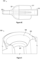
- FIG 3 illustrates an IV tubing fitment, in accordance with some implementations.
- the IV tubing fitment 310 is an example of the IV tubing fitment 54 described above in reference to Figure 2 .
- the IV tubing fitment 310 includes a unitary body 305.
- the unitary body 305 is molded.
- the unitary body 305 includes a first end 323 configured to couple to a first portion of a tubing (e.g., tube 66; Figure 2 ), a substantially hemispherical surface 321 adjacent to the first end 323, and a cylindrical body 315 adjacent to the substantially hemispherical surface 321 and configured to receive a second portion of the tubing (e.g., upstream fluid line 30; Figure 2 ).
- a tubing e.g., tube 66; Figure 2
- a substantially hemispherical surface 321 adjacent to the first end 323
- a cylindrical body 315 adjacent to the substantially hemispherical surface 321 and configured to receive
- the substantially hemispherical surface 321 is positioned between the first end 323 and the cylindrical body 315.
- the cylindrical body 315 further includes a plurality of wings 317 extending from the cylindrical body 315 towards outer rim 319.
- the plurality of wings 317 provide a user an intuitive means of determining the portion of the IV tubing fitment 310 that should be placed within a fluid delivery device (e.g., infusion pump 22; Figure 2 ).
- the plurality of wings 317 do not reach the outer rim 319 allowing the IV tubing fitment 310 to couple with the fluid delivery device restricting the IV tubing fitment 310 movement in the longitudinal and latitudinal directions while also allowing the IV tubing fitment 310 to rotate about the longitudinal axis (i.e., the plurality of wings 317 do not engage or make contact the fluid delivery device).
- the outer rim 319 is configured to engage with a door of the fluid delivery device such that when the outer rim 319 is engaged with the door of the fluid delivery device, movement of the unitary body 305 is restricted in at least one of a longitudinal and a latitudinal directions as described below in reference to Figure 8 .
- the unitary body 305 is configured to be received into a mating recess of a fluid delivery device such that the substantially hemispherical surface 321 is uniformly mated with a substantially identical surface of the mating recess of the fluid delivery device.
- the substantially hemispherical surface 321 is uniformly mated with the substantially identical surface of a mating recess 505 ( Figure 5 ) only when the first end 323 of the IV tubing fitment 310 is received within a pocket 507 of the mating recess 505 preventing the IV tubing fitment 310 from being misloaded.
- FIGS 4A-4C illustrate different views of the IV tubing fitment 310 ( Figure 3 ) in accordance with some implementations.
- a first view 410 provides a front view of the IV tubing fitment 310.
- the first view 410 shows the unitary body 305 ( Figure 3 ) including a first end 323, a substantially hemispherical surface 321 adjacent to the first end 323, and a cylindrical body 315 adjacent to the substantially hemispherical surface 321.
- the first end 323 is a nozzle configured to be fitted inside a tube 66 ( Figure 2 ).
- the tube 66 and the first end 323 are coupled such that they cannot be separated accidentally unless excessive force is applied.
- the first end 323 is molded within a portion of the tube 66 (when the unitary body 305 is molded).
- the cylindrical body 315 includes a plurality of wings 317 that extend from the center of the cylindrical body 315 towards an outer rim 319 ( Figure 3 ).
- a second view 430 provides a rear view of the IV tubing fitment 310. The second view 430 shows the unitary body 305 including the first end 323, the cylindrical body 315, and the plurality of wings 317 coupled to the cylindrical body 315.
- the cylindrical body 315 includes an opening configured to receive an upstream fluid line 30 ( Figure 2 ). In some implementations, the cylindrical body 315 receives the upstream fluid line 30 with a sufficient amount of force to prevent the cylindrical body 315 from being separated from the upstream fluid line 30 accidentally unless excessive force is applied. In some implementations, the cylindrical body 315 is molded over a portion of the upstream fluid line 30 (when the unitary body 305 is molded). By molding the cylindrical body 315 over a portion of the upstream fluid line 30, the portion of the upstream fluid line 30 is prevented from accidentally being pulled out unless excessive force is applied.
- a third view 450 provides a side view of the IV tubing fitment 310.
- the third view 450 shows the unitary body 305 including the first end 323, the substantially hemispherical surface 321 adjacent to the first end 323, the cylindrical body 315 adjacent to the substantially hemispherical surface 321, and the plurality of wings 317.
- the first, second, and third views 410, 430, and 450 illustrate that the unitary body 305 includes a constant wall thickness, draft angles, and drafts to promote easy and efficient moldability.
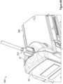
- FIG. 5 illustrates an enclosure of a fluid delivery device, in accordance with some implementations.
- Fluid delivery device 500 is an instance of any infusion pump described above in reference to Figures 1 and 2 .
- the fluid delivery device 500 includes a bezel housing 503 including a mating recess 505, and a pocket 507 on a portion of the fluid delivery device body (e.g., body 27; Figure 2 ).
- the pocket 507 is positioned at a center of the mating recess 505.
- the mating recess 505 of a fluid delivery device includes a hemispherical surface substantially identical to a substantially hemispherical surface 321 of the IV tubing fitment 310 ( Figures 3-4C ) and configured to mate with the IV tubing fitment 310.
- the mating recess 505 has a concave surface that is configured to mate with a convex surface of the IV tubing fitment 310.
- the mating recess 505 does not include any edges or steps on its mating surface, thus preventing IV tubing fitment 310 from being misloaded.
- the substantially hemispherical surface 321 of the uniform body 305 is uniformly mated with the (substantially identical) surface of the mating recess 505 only when the first end 323 of the unitary body 505 is received within the pocket 507 of the mating recess 505, which prevents the IV tubing fitment from being misloaded.
- the first portion of the tubing e.g., tube 66; Figure 2
- the first portion of the tubing coupled with the first end 323 of the unitary body is aligned along a center of the mating recess 505.
- portions of the mating recess 505 and pocket 507 are formed by the body of the fluid delivery device 500 and additional portions of the mating recess and the pocket (e.g., additional mating recess 805 and additional pocket 806; Figure 8 ) are formed by a fluid delivery device door (e.g., door 50; Figure 2 ). Additional detail on the additional mating recess 805 and the additional pocket 806 is provided below in reference to Figure 8 .
- Figures 6A-6D illustrate the loading of an IV tubing fitment into a fluid delivery device, in accordance with some implementations.
- the IV tubing fitment and fluid delivery device described in reference to Figures 6A-6D can be any IV tubing fitment and fluid delivery device described above in reference to Figures 1-5 .
- a first operational view 610 shows an IV tubing fitment 310 being positioned within a mating recess 505 and a pocket 507 (at the center of the mating recess 505) of a fluid delivery device 500 ( Figure 5 ).
- the mating recess 505 of the fluid delivery device 500 is configured to receive the IV tubing fitment 310.
- the IV tubing fitment 310 is configured such that the fluid delivery device 500 can only receive the IV tubing fitment 310 in a single configuration.
- the substantially hemispherical surface of the IV tubing fitment 310 is uniformly mated with the substantially identical surface of the mating recess 505 only when the first end 323 of the IV tubing fitment 310 is received within the pocket 507 of the mating recess 505 preventing the IV tubing fitment 310 from being misloaded.
- the substantially hemispherical surface of the IV tubing fitment 310 with the substantially identical surface 321 of the mating recess 505 without positioning the first end 323 of the IV tubing fitment 310 within the pocket 507, the substantially hemispherical surface 321 and the mating recess 505 would not be mated (which would not allow for the door 50 of the fluid delivery device 500 to close). Further, if the user does not place the first end 323 of the IV tubing fitment 310 within the pocket 507 of the mating recess 505, the door 50 of the fluid delivery device 500 would not be able to close.
- the plurality of wings 317 is further configured to operate as an intuitive indicator of the appropriate placement of the IV tubing fitment 310.
- the mating recess 505 has no edges or steps that allow the IV tubing fitment 310 to be misloaded (e.g., via the plurality of wings 317 or other surface of the IV tubing fitment 310).
- the substantially hemispherical surface 321 of the IV tubing fitment 310 and the substantially identical surface of the mating recess 505 include visual indicators of how the IV tubing fitment 310 should be placed in the fluid delivery device 500.
- the substantially hemispherical surface 321 of the IV tubing fitment 310 and the substantially identical surface of the mating recess 505 can be the same color (e.g., green) indicating to users to match the colors.
- the hemispherical surfaces on the IV tubing fitment 310 and the mating recess 505 allow easier cleaning of the IV tubing fitment 310, the mating recess 505 of fluid delivery device 500, and the door 50 of the fluid delivery device 500.
- a second operational view 620 shows the placement of the IV tubing fitment 310 within the mating recess 505 of the fluid delivery device 500.
- the IV tubing fitment 310 is received by the mating recess 505 such that the mating recess 505 is uniformly mated with the substantially hemispherical surface 321.
- a portion of the IV tubing fitment 310 is positioned outside of the body 27 ( Figure 2 ) of the fluid delivery device 500.
- a third operational view 630 provides another view of the placement of the IV tubing fitment 310 within the mating recess 505 of the fluid delivery device 500.
- the third view 630 illustrates that the substantially hemispherical surface 321 of the IV tubing fitment 310 is configured to self-center a tube 66 ( Figure 2 ).
- the first portion of the tubing i.e., tube 66
- the first portion of the tubing is aligned along a center of the mating recess 505.
- a fourth operational view 640 show the fluid delivery device 500 with its door 50 closed.
- the door 50 of the fluid delivery device 500 is closed an enclosure for the IV tubing fitment 310 is formed.
- the door 50 engages and couples with the body 27 of the fluid delivery device 500 enclosing a portion the IV tubing fitment 310 (e.g., at least the substantially hemispherical surface 321 and the first end 323 of the IV tubing fitment 310).
- the IV tubing fitment 310 While the portion of the IV tubing fitment 310 is enclosed by the fluid delivery device 500 , the IV tubing fitment 310 is unable to be moved in longitudinal and latitudinal directions (i.e., the IV tubing fitment 310 cannot be moved to the left or right, or pulled upward or pushed downwards from its position in the mating recess 505.
- the IV tubing fitment 310 is free to rotate about a longitudinal axis while keeping the IV set from kinking, twisting, and/or entangling.
- the portion of the IV tubing fitment 310 can rotate a full 360 degrees while enclosed by the fluid delivery device 500.
- Figure 7 provides a cross-sectional view 700 of an IV tubing fitment mated with at mating recess of a fluid delivery device, in accordance with some implementations.
- the IV tubing fitment and fluid delivery device shown in cross-sectional view 700 can be any IV tubing fitment the fluid delivery device described above in reference to Figures 1-6D .
- the cross-sectional view 700 includes IV tubing fitment 310 mated with the mating recess 505 of the fluid delivery device 500.
- an IV set e.g., at least an upstream fluid line 30, an tube 66, and a downstream fluid line 31; Figure 2
- an IV set is centered along a longitudinal axis such that the IV set cannot twist, entangle, or kink.
- the positioning of the IV tubing fitment 310 within the mating recess 505 of the fluid delivery device 500 and its ability to rotate about the longitudinal axis reduces the number of unintentional pulls or forces experienced by the IV set.
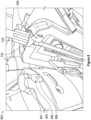
- Figure 8 illustrates a view of a door of a fluid delivery device, in accordance with some implementations.
- View 800 shows a fluid delivery device (e.g., infusion pump 22; Figure 2 ) including a door 803, a mating recess 505, a pocket 507, and an IV tubing fitment 310 mated to the mating recess 505 of the fluid delivery device 500 as described above in reference to Figures 1-7 .
- the door 803 is an example of the door 50 described above in reference to Figure 2 .
- the door 503 forms another portion of the mating recess and pocket of the fluid delivery device (e.g., additional mating recess 805 and additional pocket portion 806).
- additional mating recess 805 when the door 803 is closed while the IV tubing fitment 310 ( Figure 3 ) is mated with the mating recess 505 ( Figure 5 ), the additional mating recess 805 also mates with the IV tubing fitment 310.
- the additional mating recess 805 must also be mated with the IV tubing fitment 310.
- the door 803 is prevented from closing as described above.
- the door 803 is also prevented from closing. In this way, the IV tubing fitment 310 is not misloaded.
- the door 803 includes one or more coupling members 807 configured to engage with a portion of the IV tubing fitment 310.
- the coupling members 807 include teeth, hooks, clasps, levers, etc.
- the one or more coupling members 807 of the door 803 are configured to engage with an outer rim 319 of the IV tubing fitment 310. In some implementations, if one or more coupling members 807 of the door 803 are unable to engage with the outer rim 319 of the IV tubing fitment 310, the door 50 is prevented from closing.
- the one or more coupling members 807 engage with the outer rim 319 of the IV tubing fitment 310 such that a portion of the IV tubing fitment 310 (e.g., at least the substantially hemispherical surface 321 and the first end of the IV tubing fitment 310) is enclosed by fluid delivery device 500 ( Figure 5 ). More specifically, the one or more coupling members 807 form a lid or an enclosure with narrower diameter (with respect to a diameter of the substantially hemispherical surface 321) such that the IV tubing fitment 310 cannot be pulled from the fluid delivery device 500 while still allowing an IV set ( Figure 2 ) to rotate about a longitudinal axis.
- Figure 9 illustrates a flow diagram of a method for loading an IV set to a fluid delivery device, in accordance with some implementations.
- Method 900 can be performed using any IV tubing fitment and fluid delivery device described above in reference to Figures 1-8 .
- the method 900 includes while a door of a fluid delivery device is in an open position, receiving (902) an IV tubing fitment at a mating recess of the fluid delivery device such that a substantially hemispherical surface of an IV tubing fitment is uniformly mated with a substantially identical surface of the mating recess.
- the method 900 further includes closing (904) the door such that the door couples with the body of the fluid delivery device and forms an enclosure that configured to surrounds at least a portion of the IV tubing fitment.
- the enclosure restricts the lateral and longitudinal movement of an IV tubing fitment within the fluid delivery device while also allowing the IV tubing fitment to rotate about the longitudinal axis.
- the subject technology may be implemented without utilizing some of the components, elements, functions or operations described herein. In one aspect, the subject technology may be implemented utilizing additional components, elements, functions or operations.
- a phrase such as an "aspect” does not imply that such aspect is essential to the subject technology or that such aspect applies to all configurations of the subject technology.
- a disclosure relating to an aspect may apply to all configurations, or one or more configurations.
- An aspect may provide one or more examples.
- a phrase such as an aspect may refer to one or more aspects and vice versa.
- a phrase such as an "implementation” does not imply that such implementation is essential to the subject technology or that such implementation applies to all configurations of the subject technology.
- a disclosure relating to an implementation may apply to all implementations, or one or more implementations.
- An implementation may provide one or more examples.
- a phrase such an implementation may refer to one or more implementations and vice versa.
- a phrase such as a "configuration” does not imply that such configuration is essential to the subject technology or that such configuration applies to all configurations of the subject technology.
- a disclosure relating to a configuration may apply to all configurations, or one or more configurations.
- a configuration may provide one or more examples.
- a phrase such a configuration may refer to one or more configurations and vice versa.
- Coupled may refer to being directly coupled. In another aspect, the term “coupled,” or the like may refer to being indirectly coupled.
- top should be understood as referring to an arbitrary frame of reference, rather than to the ordinary gravitational frame of reference.
- a top surface, a bottom surface, a front surface, and a rear surface may extend upwardly, downwardly, diagonally, or horizontally in a gravitational frame of reference.
Landscapes
- Health & Medical Sciences (AREA)
- Heart & Thoracic Surgery (AREA)
- Hematology (AREA)
- Engineering & Computer Science (AREA)
- Anesthesiology (AREA)
- Biomedical Technology (AREA)
- Life Sciences & Earth Sciences (AREA)
- Animal Behavior & Ethology (AREA)
- General Health & Medical Sciences (AREA)
- Public Health (AREA)
- Veterinary Medicine (AREA)
- Pulmonology (AREA)
- Vascular Medicine (AREA)
- Infusion, Injection, And Reservoir Apparatuses (AREA)
Claims (14)
- Intravenöse, IV, Schlauchbefestigung (54, 310), umfassend:einen einheitlichen Körper (305), der so konfiguriert ist, dass er mit einer Flüssigkeitsabgabevorrichtung (22, 24, 26, 28) koppelbar ist, die einen Körper (27), der teilweise eine passende Aussparung (505) bildet, und eine Tür (50, 803) umfasst, wobei die Tür (50, 803) einen Teil der passenden Aussparung (505) bildet, wobei der einheitliche Körper (305) umfasst:ein erstes Ende (323), das so konfiguriert ist, dass es mit einem ersten Abschnitt (66) eines Rohrs verbindbar ist,eine im Wesentlichen halbkugelförmige Oberfläche (321), die an das erste Ende (323) angrenzt, undeinen zylindrischen Körper (315), der an die im Wesentlichen halbkugelförmige Oberfläche (321) angrenzt, wobei der zylindrische Körper (315) eine Vielzahl von Flügeln (317) umfasst und so konfiguriert ist, dass er einen zweiten Abschnitt (30) des Rohrs aufnimmt; undwobei der einheitliche Körper (305) so konfiguriert ist, dass er in der passenden Aussparung (505) der Fluidabgabevorrichtung (22, 24, 26, 28) aufnehmbar ist, so dass:die im Wesentlichen halbkugelförmige Oberfläche (321) so konfiguriert ist, dass sie gleichmäßig mit einer im Wesentlichen identischen Oberfläche der passenden Ausnehmung (505) zusammenpasst,der zylindrische Körper (315) so gestaltet ist, dass er außerhalb der passenden Aussparung (505) positioniert ist,wenn die Tür von einer offenen Position in eine geschlossene Position bewegt wird, während der einheitliche Körper nicht mit der passenden Aussparung in Eingriff steht, die Tür daran gehindert wird, mit dem Körper der Fluidabgabevorrichtung zu koppeln, undwenn die Tür (50, 803) von der offenen Position in die geschlossene Position bewegt wird, während der einheitliche Körper (305) mit der passenden Aussparung (505) zusammengefügt ist, der einheitliche Körper (305) so konfiguriert ist, dass er in einer Tasche (507) der Fluidabgabevorrichtung (22, 24, 26, 28) eingeschlossen ist.
- IV-Schlauchbefestigung (54, 310) nach Anspruch 1, wobei der einheitliche Körper (305), wenn er von der passenden Aussparung (505) aufgenommen ist, so konfiguriert ist, dass er sich um eine Längsachse um mindestens 270 Grad im und gegen den Uhrzeigersinn dreht.
- IV-Schlauchbefestigung (54, 310) nach Anspruch 1 oder Anspruch 2, wobei die im Wesentlichen halbkugelförmige Oberfläche (321) einen Außenrand (319) aufweist, der so konfiguriert ist, dass er mit der Tür (50, 803) der Flüssigkeitsabgabevorrichtung (22, 24, 26, 28) in Eingriff kommt.
- IV-Schlauchbefestigung (54, 310) nach Anspruch 3, wobei der äußere Rand (319), wenn er mit der Tür (50, 803) der Flüssigkeitsabgabevorrichtung (22, 24, 26, 28) in Eingriff steht, so konfiguriert ist, dass er die Bewegung des einheitlichen Körpers (305) in mindestens einer von einer Längs- und einer Querrichtung beschränkt.
- IV-Schlauchbefestigung (54, 310) nach einem der Ansprüche 1 bis 4, wobei die im Wesentlichen halbkugelförmige Oberfläche (321) so konfiguriert ist, dass sie nur dann gleichmäßig mit der im Wesentlichen identischen Oberfläche der passenden Aussparung (505) zusammenpasst, wenn das erste Ende (323) des einheitlichen Körpers (305) in der Tasche (507) der passenden Aussparung (505) aufgenommen ist, sodass verhindert wird, dass die IV-Schlauchbefestigung (54, 310) falsch belastet wird.
- IV-Schlauchbefestigung (54, 310) nach Anspruch 5, wobei, wenn das erste Ende (323) des einheitlichen Körpers (305) in der Tasche (507) der passenden Aussparung (505) aufgenommen ist, der erste Abschnitt (66) des mit dem ersten Ende (323) des einheitlichen Körpers (305) gekoppelten Schlauches entlang einer Mitte der passenden Aussparung (505) ausgerichtet ist.
- IV-Schlauchbefestigung (54, 310) nach einem der Ansprüche 1 bis 6, wobei die im Wesentlichen halbkugelförmige Oberfläche (321) einen Durchmesser aufweist, der im Wesentlichen gleich einem Durchmesser der Gegenaussparung (505) ist, wobei der Durchmesser der im Wesentlichen halbkugelförmigen Oberfläche (321) so konfiguriert ist, dass er verhindert, dass sich die Flüssigkeitsabgabevorrichtung (22, 24, 26, 28) schließt, wenn die im Wesentlichen halbkugelförmige Oberfläche (321) nicht gleichmäßig mit der im Wesentlichen identischen Oberfläche der Gegenaussparung (505) zusammenpasst.
- IV-Schlauchbefestigung (54, 310) nach einem der Ansprüche 1 bis 7, wobei die Flüssigkeitsabgabevorrichtung (22, 24, 26, 28) eine Infusionspumpe ist.
- IV-Schlauchbefestigung (54, 310) nach einem der Ansprüche 1 bis 8, wobei der einheitliche Körper (305) geformt ist.
- System (20), umfassend:eine intravenöse, IV, Schlauchbefestigung (54, 310) nach einem der Ansprüche 1 bis 6; undeine Flüssigkeitsabgabevorrichtung (22, 24, 26, 28), die einen Körper (27) umfasst, der zum Teil eine passende Aussparung (505) bildet, und eine Tür (50, 803), die einen anderen Teil der passenden Aussparung (505) bildet, wobei:während sich die Tür (50, 803) in einer offenen Position befindet, die Passungsaussparung (505) so konfiguriert ist, dass sie die IV-Schlauchbefestigung (54, 310) aufnimmt, sodass die Passungsaussparung (505) gleichmäßig mit einer im Wesentlichen halbkugelförmigen Oberfläche (321) der IV-Schlauchbefestigung (54, 310) gepaart ist, und ein Abschnitt der IV-Schlauchbefestigung (54, 310) außerhalb des Körpers (27) der Flüssigkeitsabgabevorrichtung (22, 24, 26, 28) positioniert ist;wenn die Tür in eine geschlossene Position bewegt wird, während die IV-Schlauchbefestigung nicht gleichmäßig mit der passenden Aussparung zusammenpasst, die Tür daran gehindert wird, sich mit dem Körper der Flüssigkeitsabgabevorrichtung zu verbinden; undwenn die Tür (50, 803) in die geschlossene Position bewegt wird, während das IV-Schlauchbefestigung (54, 310) mit der passenden Aussparung (505) in Eingriff steht, ist die Tür (50, 803) so konfiguriert, dass sie mit dem Körper (27) der Flüssigkeitsabgabevorrichtung (22, 24, 26, 28) gekoppelt ist und die IV-Schlauchbefestigung (54, 310) in einer Tasche (507) einschließt.
- System nach Anspruch 10, wobei die Tür (50, 803) ein oder mehrere Kopplungselemente (807) enthält, die so konfiguriert sind, dass sie mit einem Abschnitt der IV-Schlauchbefestigung (54, 310) verbunden werden können.
- System nach Anspruch 10, wobei die Tür (50, 803) so konfiguriert ist, dass sie daran gehindert wird, sich mit dem Körper (27) der Flüssigkeitsabgabevorrichtung (22, 24, 26, 28) zu koppeln, während mindestens ein Abschnitt der IV-Schlauchbefestigung (54, 310) falsch geladen ist.
- Verfahren zum Laden eines intravenösen (IV) Sets in eine Flüssigkeitsabgabevorrichtung (22, 24, 26, 28), wobei das Verfahren umfasst:bei einer Flüssigkeitsabgabevorrichtung (22, 24, 26, 28) mit einem Körper (27), der zum Teil eine Eingriffsausnehmung (505) bildet, und einer Tür (50, 803), die einen anderen Teil der Eingriffsausnehmung (505) bildet:während sich die Tür (50, 803) in einer offenen Position befindet, Aufnahme eines IV-Schlauchbefestigung (54, 310) an der passenden Aussparung (505), so dass eine im Wesentlichen halbkugelförmige Oberfläche (321) des IV-Schlauchbefestigung (54, 310) gleichmäßig mit einer im Wesentlichen identischen Oberfläche der passenden Aussparung (505) zusammenpasst;während der einheitliche Körper nicht gleichmäßig mit der passenden Ausnehmung in Eingriff gebracht wird, wodurch verhindert wird, dass die Tür mit dem Körper der Flüssigkeitsabgabevorrichtung gekoppelt wird; undSchließen der Tür (50, 803), sodass die Tür (50, 803) mit dem Körper (27) der Flüssigkeitsabgabevorrichtung (22, 24, 26, 28) gekoppelt wird und eine Umhüllung bildet, die so konfiguriert ist, dass sie mindestens einen Abschnitt der IV-Schlauchbefestigung (54, 310) umgibt,wobei die IV-Schlauchbefestigung (54, 310) umfasst:
einen einheitlichen Körper (305) mit einem ersten Ende (323), das so konfiguriert ist, dass es mit einem ersten Abschnitt (66) eines Schlauchs verbunden werden kann, wobei die im Wesentlichen halbkugelförmige Oberfläche (321) an das erste Ende (323) angrenzt, und einen zylindrischen Körper (315), der an die im Wesentlichen halbkugelförmige Oberfläche (321) angrenzt, wobei der zylindrische Körper (315) eine Vielzahl von Flügeln (317) aufweist und so konfiguriert ist, dass er einen zweiten Abschnitt (30) des Schlauchs aufnimmt,wobei das Aufnehmen der IV-Schlauchbefestigung (54, 310) an der passenden Aussparung (505) umfasst:
Aufnehmen der IV-Schlauchbefestigung (54, 310) in der passenden Aussparung (505) der Flüssigkeitsabgabevorrichtung (22, 24, 26, 28), sodass der zylindrische Körper (315) außerhalb der passenden Aussparung (505) positioniert ist, während die im Wesentlichen halbkugelförmige Oberfläche (321) gleichmäßig mit der im Wesentlichen identischen Oberfläche der passenden Aussparung (505) in Eingriff gebracht wird. - Verfahren nach Anspruch 13, ferner umfassend:gleichmäßiges Zusammenpassen der im Wesentlichen halbkugelförmigen Oberfläche (321) mit der im Wesentlichen identischen Oberfläche der passenden Aussparung (505) nur dann, wenn das erste Ende (323) des einheitlichen Körpers (305) in einer Tasche (507) der passenden Aussparung (505) aufgenommen ist, wodurch verhindert wird, dass das IV-Schlauchbefestigung (54, 310) falsch belastet wird, undAufnehmen der IV-Schlauchbefestigung (54, 310) in der Tasche (507) der passenden Aussparung (505), so dass der erste Abschnitt (66) des mit dem ersten Ende (323) des einheitlichen Körpers (305) gekoppelten Schlauchs entlang einer Mitte der passenden Aussparung (505) ausgerichtet ist.
Applications Claiming Priority (1)
| Application Number | Priority Date | Filing Date | Title |
|---|---|---|---|
| US202163239327P | 2021-08-31 | 2021-08-31 |
Publications (3)
| Publication Number | Publication Date |
|---|---|
| EP4140519A1 EP4140519A1 (de) | 2023-03-01 |
| EP4140519B1 true EP4140519B1 (de) | 2025-05-07 |
| EP4140519C0 EP4140519C0 (de) | 2025-05-07 |
Family
ID=83151548
Family Applications (1)
| Application Number | Title | Priority Date | Filing Date |
|---|---|---|---|
| EP22193186.8A Active EP4140519B1 (de) | 2021-08-31 | 2022-08-31 | Anschluss eines intravenösen schlauches, system und ladeverfahren |
Country Status (4)
| Country | Link |
|---|---|
| US (1) | US20230067977A1 (de) |
| EP (1) | EP4140519B1 (de) |
| CN (2) | CN115721807A (de) |
| CA (1) | CA3171739A1 (de) |
Families Citing this family (2)
| Publication number | Priority date | Publication date | Assignee | Title |
|---|---|---|---|---|
| CN117462800A (zh) * | 2023-12-27 | 2024-01-30 | 广州君霖医疗科技有限公司 | 加压雾化设备用导管、蠕动泵及加压雾化设备 |
| CN119818763B (zh) * | 2025-03-18 | 2025-06-17 | 四川省肿瘤医院 | 一种可定量控制的输液导管装置 |
Family Cites Families (6)
| Publication number | Priority date | Publication date | Assignee | Title |
|---|---|---|---|---|
| US4875718A (en) * | 1988-12-02 | 1989-10-24 | Marken Robert E | Swivel connector for preventing kinking of flexible medical hoses |
| GB2379253B (en) * | 2001-09-04 | 2005-09-14 | Clinical Product Dev Ltd | Couplings for medical fluid delivery systems |
| FR2863162B1 (fr) * | 2003-12-05 | 2006-12-08 | Vygon | Raccords males et raccords femelles pour realiser des connexions de transmission de liquide, notamment pour des lignes de nutrition enterale |
| FR2901481B1 (fr) * | 2006-05-24 | 2009-01-23 | Ace Dev Solution Soc A Respons | Connecteur luer lock male |
| US9220883B2 (en) * | 2010-09-14 | 2015-12-29 | Cedic S.R.L. | Medical connector |
| US11045599B2 (en) * | 2015-12-14 | 2021-06-29 | Carefusion 303, Inc. | Self-compensating chucking device for infusion pump systems |
-
2022
- 2022-08-30 US US17/899,031 patent/US20230067977A1/en active Pending
- 2022-08-30 CA CA3171739A patent/CA3171739A1/en active Pending
- 2022-08-31 EP EP22193186.8A patent/EP4140519B1/de active Active
- 2022-08-31 CN CN202211071366.9A patent/CN115721807A/zh active Pending
- 2022-08-31 CN CN202222303662.9U patent/CN219814892U/zh active Active
Also Published As
| Publication number | Publication date |
|---|---|
| CN115721807A (zh) | 2023-03-03 |
| EP4140519A1 (de) | 2023-03-01 |
| CA3171739A1 (en) | 2023-02-28 |
| US20230067977A1 (en) | 2023-03-02 |
| CN219814892U (zh) | 2023-10-13 |
| EP4140519C0 (de) | 2025-05-07 |
Similar Documents
| Publication | Publication Date | Title |
|---|---|---|
| US10226571B2 (en) | Pump segment placement | |
| AU2019253887B2 (en) | Single-use disposable set connector | |
| JP5805669B2 (ja) | 流体供給システムを位置付けるためのシステムと方法 | |
| CN103402481B (zh) | 用于输液的插件和小瓶 | |
| US9598210B2 (en) | Reservoir pressure equalization systems and methods | |
| JP2021164646A (ja) | 多数の薬剤の誤送出を防止するための注入システム | |
| US8016790B2 (en) | Infusion status indicator | |
| US20100022988A1 (en) | Infusion set with a data storage device | |
| CA2840198C (en) | Medicament infusion systems and fitting therefor | |
| US9468714B2 (en) | Memory and identification associated with IV set | |
| EP4140519B1 (de) | Anschluss eines intravenösen schlauches, system und ladeverfahren | |
| WO2023244922A2 (en) | Systems and methods for substantially continuous intravenous infusion of the same or substantially the same medical fluid with fluid source replacements | |
| US20140271247A1 (en) | Infusion pump configured to engage a sensor with tubing | |
| US9114206B2 (en) | Device for infusion of prescription medicines or treatments | |
| US20140271246A1 (en) | Cooperation of platen and pump cassette for pump device | |
| US9968739B2 (en) | Rotary valve for a disposable infusion set | |
| US12427295B2 (en) | Catheter flush device, system, and methods | |
| CA3230748A1 (en) | Male luer connector | |
| WO2014159466A1 (en) | Disposable infusion set | |
| WO2023129403A1 (en) | Intravenous pressure assembly | |
| CN105771020A (zh) | 自动换袋输液器 |
Legal Events
| Date | Code | Title | Description |
|---|---|---|---|
| PUAI | Public reference made under article 153(3) epc to a published international application that has entered the european phase |
Free format text: ORIGINAL CODE: 0009012 |
|
| STAA | Information on the status of an ep patent application or granted ep patent |
Free format text: STATUS: THE APPLICATION HAS BEEN PUBLISHED |
|
| AK | Designated contracting states |
Kind code of ref document: A1 Designated state(s): AL AT BE BG CH CY CZ DE DK EE ES FI FR GB GR HR HU IE IS IT LI LT LU LV MC MK MT NL NO PL PT RO RS SE SI SK SM TR |
|
| STAA | Information on the status of an ep patent application or granted ep patent |
Free format text: STATUS: REQUEST FOR EXAMINATION WAS MADE |
|
| 17P | Request for examination filed |
Effective date: 20230901 |
|
| RBV | Designated contracting states (corrected) |
Designated state(s): AL AT BE BG CH CY CZ DE DK EE ES FI FR GB GR HR HU IE IS IT LI LT LU LV MC MK MT NL NO PL PT RO RS SE SI SK SM TR |
|
| STAA | Information on the status of an ep patent application or granted ep patent |
Free format text: STATUS: EXAMINATION IS IN PROGRESS |
|
| 17Q | First examination report despatched |
Effective date: 20240214 |
|
| GRAP | Despatch of communication of intention to grant a patent |
Free format text: ORIGINAL CODE: EPIDOSNIGR1 |
|
| STAA | Information on the status of an ep patent application or granted ep patent |
Free format text: STATUS: GRANT OF PATENT IS INTENDED |
|
| INTG | Intention to grant announced |
Effective date: 20241202 |
|
| GRAS | Grant fee paid |
Free format text: ORIGINAL CODE: EPIDOSNIGR3 |
|
| GRAA | (expected) grant |
Free format text: ORIGINAL CODE: 0009210 |
|
| STAA | Information on the status of an ep patent application or granted ep patent |
Free format text: STATUS: THE PATENT HAS BEEN GRANTED |
|
| AK | Designated contracting states |
Kind code of ref document: B1 Designated state(s): AL AT BE BG CH CY CZ DE DK EE ES FI FR GB GR HR HU IE IS IT LI LT LU LV MC MK MT NL NO PL PT RO RS SE SI SK SM TR |
|
| REG | Reference to a national code |
Ref country code: GB Ref legal event code: FG4D |
|
| REG | Reference to a national code |
Ref country code: CH Ref legal event code: EP |
|
| REG | Reference to a national code |
Ref country code: DE Ref legal event code: R096 Ref document number: 602022014158 Country of ref document: DE |
|
| REG | Reference to a national code |
Ref country code: IE Ref legal event code: FG4D |
|
| U01 | Request for unitary effect filed |
Effective date: 20250603 |
|
| U07 | Unitary effect registered |
Designated state(s): AT BE BG DE DK EE FI FR IT LT LU LV MT NL PT RO SE SI Effective date: 20250610 |
|
| U20 | Renewal fee for the european patent with unitary effect paid |
Year of fee payment: 4 Effective date: 20250723 |
|
| PG25 | Lapsed in a contracting state [announced via postgrant information from national office to epo] |
Ref country code: ES Free format text: LAPSE BECAUSE OF FAILURE TO SUBMIT A TRANSLATION OF THE DESCRIPTION OR TO PAY THE FEE WITHIN THE PRESCRIBED TIME-LIMIT Effective date: 20250507 |
|
| PG25 | Lapsed in a contracting state [announced via postgrant information from national office to epo] |
Ref country code: GR Free format text: LAPSE BECAUSE OF FAILURE TO SUBMIT A TRANSLATION OF THE DESCRIPTION OR TO PAY THE FEE WITHIN THE PRESCRIBED TIME-LIMIT Effective date: 20250808 Ref country code: NO Free format text: LAPSE BECAUSE OF FAILURE TO SUBMIT A TRANSLATION OF THE DESCRIPTION OR TO PAY THE FEE WITHIN THE PRESCRIBED TIME-LIMIT Effective date: 20250807 |
|
| PG25 | Lapsed in a contracting state [announced via postgrant information from national office to epo] |
Ref country code: PL Free format text: LAPSE BECAUSE OF FAILURE TO SUBMIT A TRANSLATION OF THE DESCRIPTION OR TO PAY THE FEE WITHIN THE PRESCRIBED TIME-LIMIT Effective date: 20250507 |
|
| PG25 | Lapsed in a contracting state [announced via postgrant information from national office to epo] |
Ref country code: HR Free format text: LAPSE BECAUSE OF FAILURE TO SUBMIT A TRANSLATION OF THE DESCRIPTION OR TO PAY THE FEE WITHIN THE PRESCRIBED TIME-LIMIT Effective date: 20250507 |
|
| PG25 | Lapsed in a contracting state [announced via postgrant information from national office to epo] |
Ref country code: RS Free format text: LAPSE BECAUSE OF FAILURE TO SUBMIT A TRANSLATION OF THE DESCRIPTION OR TO PAY THE FEE WITHIN THE PRESCRIBED TIME-LIMIT Effective date: 20250807 |
|
| PG25 | Lapsed in a contracting state [announced via postgrant information from national office to epo] |
Ref country code: IS Free format text: LAPSE BECAUSE OF FAILURE TO SUBMIT A TRANSLATION OF THE DESCRIPTION OR TO PAY THE FEE WITHIN THE PRESCRIBED TIME-LIMIT Effective date: 20250907 |
|
| PG25 | Lapsed in a contracting state [announced via postgrant information from national office to epo] |
Ref country code: SM Free format text: LAPSE BECAUSE OF FAILURE TO SUBMIT A TRANSLATION OF THE DESCRIPTION OR TO PAY THE FEE WITHIN THE PRESCRIBED TIME-LIMIT Effective date: 20250507 |
|
| PG25 | Lapsed in a contracting state [announced via postgrant information from national office to epo] |
Ref country code: CZ Free format text: LAPSE BECAUSE OF FAILURE TO SUBMIT A TRANSLATION OF THE DESCRIPTION OR TO PAY THE FEE WITHIN THE PRESCRIBED TIME-LIMIT Effective date: 20250507 |
|
| PG25 | Lapsed in a contracting state [announced via postgrant information from national office to epo] |
Ref country code: SK Free format text: LAPSE BECAUSE OF FAILURE TO SUBMIT A TRANSLATION OF THE DESCRIPTION OR TO PAY THE FEE WITHIN THE PRESCRIBED TIME-LIMIT Effective date: 20250507 |
|
| PLBE | No opposition filed within time limit |
Free format text: ORIGINAL CODE: 0009261 |
|
| STAA | Information on the status of an ep patent application or granted ep patent |
Free format text: STATUS: NO OPPOSITION FILED WITHIN TIME LIMIT |
|
| REG | Reference to a national code |
Ref country code: CH Ref legal event code: L10 Free format text: ST27 STATUS EVENT CODE: U-0-0-L10-L00 (AS PROVIDED BY THE NATIONAL OFFICE) Effective date: 20260318 |
|
| REG | Reference to a national code |
Ref country code: CH Ref legal event code: H13 Free format text: ST27 STATUS EVENT CODE: U-0-0-H10-H13 (AS PROVIDED BY THE NATIONAL OFFICE) Effective date: 20260324 |
|
| PG25 | Lapsed in a contracting state [announced via postgrant information from national office to epo] |
Ref country code: MC Free format text: LAPSE BECAUSE OF FAILURE TO SUBMIT A TRANSLATION OF THE DESCRIPTION OR TO PAY THE FEE WITHIN THE PRESCRIBED TIME-LIMIT Effective date: 20250507 |
|
| 26N | No opposition filed |
Effective date: 20260210 |
|
| PG25 | Lapsed in a contracting state [announced via postgrant information from national office to epo] |
Ref country code: CH Free format text: LAPSE BECAUSE OF NON-PAYMENT OF DUE FEES Effective date: 20250831 |