EP4140446A1 - Leaflet suturing to commissure points for prosthetic heart valve - Google Patents
Leaflet suturing to commissure points for prosthetic heart valve Download PDFInfo
- Publication number
- EP4140446A1 EP4140446A1 EP22184311.3A EP22184311A EP4140446A1 EP 4140446 A1 EP4140446 A1 EP 4140446A1 EP 22184311 A EP22184311 A EP 22184311A EP 4140446 A1 EP4140446 A1 EP 4140446A1
- Authority
- EP
- European Patent Office
- Prior art keywords
- leaflet
- prosthetic heart
- heart valve
- stent
- edge
- Prior art date
- Legal status (The legal status is an assumption and is not a legal conclusion. Google has not performed a legal analysis and makes no representation as to the accuracy of the status listed.)
- Granted
Links
Images




Classifications
-
- A—HUMAN NECESSITIES
- A61—MEDICAL OR VETERINARY SCIENCE; HYGIENE
- A61F—FILTERS IMPLANTABLE INTO BLOOD VESSELS; PROSTHESES; DEVICES PROVIDING PATENCY TO, OR PREVENTING COLLAPSING OF, TUBULAR STRUCTURES OF THE BODY, e.g. STENTS; ORTHOPAEDIC, NURSING OR CONTRACEPTIVE DEVICES; FOMENTATION; TREATMENT OR PROTECTION OF EYES OR EARS; BANDAGES, DRESSINGS OR ABSORBENT PADS; FIRST-AID KITS
- A61F2/00—Filters implantable into blood vessels; Prostheses, i.e. artificial substitutes or replacements for parts of the body; Appliances for connecting them with the body; Devices providing patency to, or preventing collapsing of, tubular structures of the body, e.g. stents
- A61F2/02—Prostheses implantable into the body
- A61F2/24—Heart valves ; Vascular valves, e.g. venous valves; Heart implants, e.g. passive devices for improving the function of the native valve or the heart muscle; Transmyocardial revascularisation [TMR] devices; Valves implantable in the body
- A61F2/2412—Heart valves ; Vascular valves, e.g. venous valves; Heart implants, e.g. passive devices for improving the function of the native valve or the heart muscle; Transmyocardial revascularisation [TMR] devices; Valves implantable in the body with soft flexible valve members, e.g. tissue valves shaped like natural valves
- A61F2/2418—Scaffolds therefor, e.g. support stents
-
- A—HUMAN NECESSITIES
- A61—MEDICAL OR VETERINARY SCIENCE; HYGIENE
- A61F—FILTERS IMPLANTABLE INTO BLOOD VESSELS; PROSTHESES; DEVICES PROVIDING PATENCY TO, OR PREVENTING COLLAPSING OF, TUBULAR STRUCTURES OF THE BODY, e.g. STENTS; ORTHOPAEDIC, NURSING OR CONTRACEPTIVE DEVICES; FOMENTATION; TREATMENT OR PROTECTION OF EYES OR EARS; BANDAGES, DRESSINGS OR ABSORBENT PADS; FIRST-AID KITS
- A61F2/00—Filters implantable into blood vessels; Prostheses, i.e. artificial substitutes or replacements for parts of the body; Appliances for connecting them with the body; Devices providing patency to, or preventing collapsing of, tubular structures of the body, e.g. stents
- A61F2/02—Prostheses implantable into the body
- A61F2/24—Heart valves ; Vascular valves, e.g. venous valves; Heart implants, e.g. passive devices for improving the function of the native valve or the heart muscle; Transmyocardial revascularisation [TMR] devices; Valves implantable in the body
- A61F2/2412—Heart valves ; Vascular valves, e.g. venous valves; Heart implants, e.g. passive devices for improving the function of the native valve or the heart muscle; Transmyocardial revascularisation [TMR] devices; Valves implantable in the body with soft flexible valve members, e.g. tissue valves shaped like natural valves
-
- A—HUMAN NECESSITIES
- A61—MEDICAL OR VETERINARY SCIENCE; HYGIENE
- A61F—FILTERS IMPLANTABLE INTO BLOOD VESSELS; PROSTHESES; DEVICES PROVIDING PATENCY TO, OR PREVENTING COLLAPSING OF, TUBULAR STRUCTURES OF THE BODY, e.g. STENTS; ORTHOPAEDIC, NURSING OR CONTRACEPTIVE DEVICES; FOMENTATION; TREATMENT OR PROTECTION OF EYES OR EARS; BANDAGES, DRESSINGS OR ABSORBENT PADS; FIRST-AID KITS
- A61F2/00—Filters implantable into blood vessels; Prostheses, i.e. artificial substitutes or replacements for parts of the body; Appliances for connecting them with the body; Devices providing patency to, or preventing collapsing of, tubular structures of the body, e.g. stents
- A61F2/02—Prostheses implantable into the body
- A61F2/24—Heart valves ; Vascular valves, e.g. venous valves; Heart implants, e.g. passive devices for improving the function of the native valve or the heart muscle; Transmyocardial revascularisation [TMR] devices; Valves implantable in the body
- A61F2/2427—Devices for manipulating or deploying heart valves during implantation
-
- A—HUMAN NECESSITIES
- A61—MEDICAL OR VETERINARY SCIENCE; HYGIENE
- A61F—FILTERS IMPLANTABLE INTO BLOOD VESSELS; PROSTHESES; DEVICES PROVIDING PATENCY TO, OR PREVENTING COLLAPSING OF, TUBULAR STRUCTURES OF THE BODY, e.g. STENTS; ORTHOPAEDIC, NURSING OR CONTRACEPTIVE DEVICES; FOMENTATION; TREATMENT OR PROTECTION OF EYES OR EARS; BANDAGES, DRESSINGS OR ABSORBENT PADS; FIRST-AID KITS
- A61F2/00—Filters implantable into blood vessels; Prostheses, i.e. artificial substitutes or replacements for parts of the body; Appliances for connecting them with the body; Devices providing patency to, or preventing collapsing of, tubular structures of the body, e.g. stents
- A61F2/02—Prostheses implantable into the body
- A61F2/24—Heart valves ; Vascular valves, e.g. venous valves; Heart implants, e.g. passive devices for improving the function of the native valve or the heart muscle; Transmyocardial revascularisation [TMR] devices; Valves implantable in the body
- A61F2/2427—Devices for manipulating or deploying heart valves during implantation
- A61F2/2436—Deployment by retracting a sheath
-
- A—HUMAN NECESSITIES
- A61—MEDICAL OR VETERINARY SCIENCE; HYGIENE
- A61F—FILTERS IMPLANTABLE INTO BLOOD VESSELS; PROSTHESES; DEVICES PROVIDING PATENCY TO, OR PREVENTING COLLAPSING OF, TUBULAR STRUCTURES OF THE BODY, e.g. STENTS; ORTHOPAEDIC, NURSING OR CONTRACEPTIVE DEVICES; FOMENTATION; TREATMENT OR PROTECTION OF EYES OR EARS; BANDAGES, DRESSINGS OR ABSORBENT PADS; FIRST-AID KITS
- A61F2/00—Filters implantable into blood vessels; Prostheses, i.e. artificial substitutes or replacements for parts of the body; Appliances for connecting them with the body; Devices providing patency to, or preventing collapsing of, tubular structures of the body, e.g. stents
- A61F2/95—Instruments specially adapted for placement or removal of stents or stent-grafts
-
- A—HUMAN NECESSITIES
- A61—MEDICAL OR VETERINARY SCIENCE; HYGIENE
- A61F—FILTERS IMPLANTABLE INTO BLOOD VESSELS; PROSTHESES; DEVICES PROVIDING PATENCY TO, OR PREVENTING COLLAPSING OF, TUBULAR STRUCTURES OF THE BODY, e.g. STENTS; ORTHOPAEDIC, NURSING OR CONTRACEPTIVE DEVICES; FOMENTATION; TREATMENT OR PROTECTION OF EYES OR EARS; BANDAGES, DRESSINGS OR ABSORBENT PADS; FIRST-AID KITS
- A61F2/00—Filters implantable into blood vessels; Prostheses, i.e. artificial substitutes or replacements for parts of the body; Appliances for connecting them with the body; Devices providing patency to, or preventing collapsing of, tubular structures of the body, e.g. stents
- A61F2/95—Instruments specially adapted for placement or removal of stents or stent-grafts
- A61F2/9517—Instruments specially adapted for placement or removal of stents or stent-grafts handle assemblies therefor
-
- A—HUMAN NECESSITIES
- A61—MEDICAL OR VETERINARY SCIENCE; HYGIENE
- A61F—FILTERS IMPLANTABLE INTO BLOOD VESSELS; PROSTHESES; DEVICES PROVIDING PATENCY TO, OR PREVENTING COLLAPSING OF, TUBULAR STRUCTURES OF THE BODY, e.g. STENTS; ORTHOPAEDIC, NURSING OR CONTRACEPTIVE DEVICES; FOMENTATION; TREATMENT OR PROTECTION OF EYES OR EARS; BANDAGES, DRESSINGS OR ABSORBENT PADS; FIRST-AID KITS
- A61F2/00—Filters implantable into blood vessels; Prostheses, i.e. artificial substitutes or replacements for parts of the body; Appliances for connecting them with the body; Devices providing patency to, or preventing collapsing of, tubular structures of the body, e.g. stents
- A61F2/95—Instruments specially adapted for placement or removal of stents or stent-grafts
- A61F2002/9534—Instruments specially adapted for placement or removal of stents or stent-grafts for repositioning of stents
-
- A—HUMAN NECESSITIES
- A61—MEDICAL OR VETERINARY SCIENCE; HYGIENE
- A61F—FILTERS IMPLANTABLE INTO BLOOD VESSELS; PROSTHESES; DEVICES PROVIDING PATENCY TO, OR PREVENTING COLLAPSING OF, TUBULAR STRUCTURES OF THE BODY, e.g. STENTS; ORTHOPAEDIC, NURSING OR CONTRACEPTIVE DEVICES; FOMENTATION; TREATMENT OR PROTECTION OF EYES OR EARS; BANDAGES, DRESSINGS OR ABSORBENT PADS; FIRST-AID KITS
- A61F2220/00—Fixations or connections for prostheses classified in groups A61F2/00 - A61F2/26 or A61F2/82 or A61F9/00 or A61F11/00 or subgroups thereof
- A61F2220/0025—Connections or couplings between prosthetic parts, e.g. between modular parts; Connecting elements
- A61F2220/0075—Connections or couplings between prosthetic parts, e.g. between modular parts; Connecting elements sutured, ligatured or stitched, retained or tied with a rope, string, thread, wire or cable
-
- A—HUMAN NECESSITIES
- A61—MEDICAL OR VETERINARY SCIENCE; HYGIENE
- A61F—FILTERS IMPLANTABLE INTO BLOOD VESSELS; PROSTHESES; DEVICES PROVIDING PATENCY TO, OR PREVENTING COLLAPSING OF, TUBULAR STRUCTURES OF THE BODY, e.g. STENTS; ORTHOPAEDIC, NURSING OR CONTRACEPTIVE DEVICES; FOMENTATION; TREATMENT OR PROTECTION OF EYES OR EARS; BANDAGES, DRESSINGS OR ABSORBENT PADS; FIRST-AID KITS
- A61F2230/00—Geometry of prostheses classified in groups A61F2/00 - A61F2/26 or A61F2/82 or A61F9/00 or A61F11/00 or subgroups thereof
- A61F2230/0002—Two-dimensional shapes, e.g. cross-sections
- A61F2230/0004—Rounded shapes, e.g. with rounded corners
- A61F2230/0013—Horseshoe-shaped, e.g. crescent-shaped, C-shaped, U-shaped
-
- A—HUMAN NECESSITIES
- A61—MEDICAL OR VETERINARY SCIENCE; HYGIENE
- A61F—FILTERS IMPLANTABLE INTO BLOOD VESSELS; PROSTHESES; DEVICES PROVIDING PATENCY TO, OR PREVENTING COLLAPSING OF, TUBULAR STRUCTURES OF THE BODY, e.g. STENTS; ORTHOPAEDIC, NURSING OR CONTRACEPTIVE DEVICES; FOMENTATION; TREATMENT OR PROTECTION OF EYES OR EARS; BANDAGES, DRESSINGS OR ABSORBENT PADS; FIRST-AID KITS
- A61F2250/00—Special features of prostheses classified in groups A61F2/00 - A61F2/26 or A61F2/82 or A61F9/00 or A61F11/00 or subgroups thereof
- A61F2250/0014—Special features of prostheses classified in groups A61F2/00 - A61F2/26 or A61F2/82 or A61F9/00 or A61F11/00 or subgroups thereof having different values of a given property or geometrical feature, e.g. mechanical property or material property, at different locations within the same prosthesis
- A61F2250/0039—Special features of prostheses classified in groups A61F2/00 - A61F2/26 or A61F2/82 or A61F9/00 or A61F11/00 or subgroups thereof having different values of a given property or geometrical feature, e.g. mechanical property or material property, at different locations within the same prosthesis differing in diameter
Definitions
- the present invention relates to heart valve replacement and, in particular, to collapsible prosthetic heart valves. More particularly, the present invention relates to collapsible prosthetic heart valves.
- Prosthetic heart valves that are collapsible to a relatively small circumferential size can be delivered into a patient less invasively than valves that are not collapsible.
- a collapsible valve may be delivered into a patient via a tube-like delivery apparatus such as a catheter, a trocar, a laparoscopic instrument, or the like. This collapsibility can avoid the need for a more invasive procedure such as full open-chest, open-heart surgery.
- Collapsible prosthetic heart valves typically take the form of a valve assembly or structure mounted on a stent.
- stents There are many types of stents that may be used.
- two types of stents on which the valve structures are ordinarily mounted include: a self-expanding stent and a balloon-expandable stent. To place such valves into a delivery apparatus and ultimately into a patient, the valve must first be collapsed or crimped to reduce its circumferential size.
- the prosthetic valve When a collapsed prosthetic valve has reached the desired implantation site in the patient (e.g., at or near the annulus of the patient's heart valve that is to be replaced by the prosthetic valve), the prosthetic valve can be deployed or released from the delivery apparatus and expanded to the full operating size.
- the desired implantation site in the patient e.g., at or near the annulus of the patient's heart valve that is to be replaced by the prosthetic valve
- the prosthetic valve can be deployed or released from the delivery apparatus and expanded to the full operating size.
- this generally involves releasing the entire valve, assuring its proper location, and then expanding a balloon positioned within the stent.
- self-expanding stents on the other hand, the stent automatically expands as the sheath covering the valve is withdrawn.
- the prosthetic heart valve includes a stent and a valve assembly.
- the stent has a collapsed condition and an expanded condition and includes a plurality of commissure points disposed thereon.
- the valve assembly is secured to the stent and includes a plurality of leaflets. Each leaflet includes a free edge. An end portion of the free edge of the leaflet is folded and sutured to a corresponding one of the plurality of the commissure points.
- the end portions of the free edges of first and second adjacent leaflets are sutured to one another.
- the prosthetic heart valve further includes a reinforcement layer disposed between the folded end portions of the free edge of the leaflet.
- the folded end portion of the free edge of the leaflet is generally parallel to the immediately adjacent portions of the leaflet and/or generally perpendicular to the commissure point. In other embodiments, the folded end portion of the free edge of the leaflet is generally perpendicular to the immediately adjacent portions of the leaflet and/or generally parallel to the commissure point.
- the free end of the folded end portion of the free edge of the leaflet may extend beyond the suture toward the immediately adjacent portion of the leaflet.
- the end portion of the free edge of the leaflet may be rolled into a generally spiral configuration.
- the folded end portion of the free edge of the leaflet may include two or more folds.
- the end portion of the free edge of the leaflet may wrap at least partially around the commissure point.
- a web overlying the end portion of the free edge of the leaflet may substantially wrap around the commissure point and may be sutured to be end portion and the commissure point.
- the leaflet may include "tabs" or ends which are attached to the commissure points or a portion of the attached edge may be sutured thereto.
- a prosthetic heart valve includes a stent and a valve assembly disposed within the stent.
- Each of the stent and the valve assembly has a collapsed condition and an expanded condition.
- the stent has a proximal end and a distal end.
- a plurality of commissure points is disposed on the stent.
- the valve assembly includes a plurality of leaflets, each of which has a free edge. An end portion of the free edge of the leaflet is folded and sutured to a corresponding one of the commissure points. The end portion is folded in a configuration selected from the group consisting of a U-shaped pleat, an S-shaped pleat, a generally spiral roll and a U-shaped pleat enveloped by an external web.
- proximal when used in connection with a prosthetic heart valve, refers to the end of the heart valve closest to the heart when the heart valve is implanted in a patient
- distal when used in connection with a prosthetic heart valve, refers to the end of the heart valve farthest from the heart when the heart valve is implanted in a patient.
- a collapsible prosthetic heart valve 100 typically includes a stent or frame 102 supporting a valve assembly 104.
- Examples of collapsible prosthetic heart valves are described in International Patent Application Publication No. WO/2009/042196 ; United States Patent No. 7,018,406 ; United States Patent No. 7,329,278 , United States Patent Application Publication Nos. 2005/0113910 and 2009/0030511 , the disclosures of all of which are hereby incorporated herein by reference.
- the prosthetic heart valve 100 is designed to replace the function of a native aortic valve of a patient. As discussed in detail below, the prosthetic heart valve has an expanded condition and a collapsed condition. Although the invention is described herein as applied to a prosthetic heart valve for replacing a native aortic valve, the invention is not so limited, and may be applied to prosthetic valves for replacing other types of cardiac valves.
- the prosthetic heart valve 100 includes a stent or frame 102, which may be wholly or partly formed of any biocompatible material, such as metals, synthetic polymers, or biopolymers capable of functioning as a stent.
- Suitable biopolymers include, but are not limited to, elastin, and mixtures or composites thereof.
- Suitable metals include, but are not limited to, cobalt, titanium, nickel, chromium, stainless steel, and alloys thereof, including nitinol.
- Suitable synthetic polymers for use as a stent include, but are not limited to, thermoplastics, such as polyolefins, polyesters, polyamides, polysulfones, acrylics, polyacrylonitriles, polyetheretherketone (PEEK), and polyaramides.
- the stent 102 may have an annulus section 110 and an aortic section (not shown). Each of the annulus section 110 and the aortic section of the stent 102 includes a plurality of cells 112 connected to one another around the stent.
- the annulus section 110 and the aortic section of the stent 102 may include one or more annular rows of cells 112 connected to one another. For instance, the annulus section 110 may have two annular rows of cells 112.
- each cell 112 When the prosthetic heart valve 100 is in the expanded condition, each cell 112 may be substantially diamond shaped. Regardless of its shape, each cell 112 is formed by a plurality of struts 114. For example, a cell 112 may be formed by four struts 114.
- the stent 102 may include commissure points 116 connecting at least two cells 112 in the longitudinal direction of the stent 102.
- the commissure points 116 may include eyelets for facilitating the suturing of a valve assembly 104 to the stent 102.
- the prosthetic heart valve 100 also includes a valve assembly 104 attached inside the annulus section 110 of the stent 102.
- a valve assembly 104 may be wholly or partly formed of any suitable biological material or polymer materials in the forms of sheets, non-woven and woven fabrics and the like. Examples of biological materials suitable for the valve assembly 104 include, but are not limited to, porcine or bovine pericardial tissue. Examples of polymers suitable for the valve assembly 104 include, but are not limited to, polyurethane and polyester.
- the valve assembly 104 may include a cuff 106 disposed on the lumenal surface of annulus section 110, on the ablumenal surface of annulus section 110, or on both surfaces, and the cuff may cover all or part of either or both of the lumenal and ablumenal surfaces of the annulus section.
- FIG. 1 shows cuff 106 disposed on the lumenal surface of annulus section 110 so as to cover part of the annulus section while leaving another part thereof uncovered.
- the valve assembly 104 may further include a plurality of leaflets 108 which collectively function as a one-way valve.
- a first edge 122 of each leaflet 108 may be attached to the stent 102 by any suitable attachment means, such as suturing, stapling, adhesives or the like.
- a second or free edge 124 of each leaflet 108 may coapt with the corresponding free edges of the other leaflets, thereby enabling the leaflets to function collectively as a one-way valve.
- the leaflets 108 may be attached to the stent 102 along at least some struts 114 of the stent 102 to enhance the structural integrity of the valve assembly 104.
- the struts 114 help support the leaflets 108 of the valve assembly 104 and may therefore reduce the strain in the leaflets.
- At least one leaflet 108 may be attached to the stent 102 so that its first edge 122 is disposed substantially along specific struts 114a, 114b, 114c, 114d, 114e and 114f located in the annulus section 110 of the stent. That is, the edge 122 is positioned in substantial alignment with struts 114a, 114b, 114c, 114d, 114e, and 114f. Also as shown, the edge 122 can be roughly parallel to the edge of the cuff 106. However, of course, the cuff 106 need not be cut to follow the slope or pattern of the struts.
- Struts 114a, 114b, and 114c may be connected to one another in substantially end-to-end fashion diagonally along three cells 112, beginning with an end of the strut 114a connected to a commissure point 116 and ending with an end of strut 114c connected to an end of strut 114d.
- Struts 114c and 114d are part of the same cell 112 and may collectively define a substantially right angle between them.
- Struts 114d, 114e, and 114f may be connected to one another in substantially end-to-end fashion diagonally along three cells 112, beginning with an end of the strut 114f connected to a commissure point 116 and ending with the connection between an end of strut 114c and an end of strut 114d.
- the leaflets 108 may be attached directly to and supported by the struts 114a, 114b, 114c, 114d, 114e, and 114f, such as by suturing.
- the cuff 106 may perform little or no supportive function for the leaflets 108, and the thickness of the cuff 106 may, therefore, be reduced. Reducing the thickness of the cuff 106 results in a decrease in the volume of the valve assembly 104 in the collapsed condition. This decreased volume is desirable as it enables the prosthetic heart valve 100 to be implanted in a patient using a delivery device that is smaller than conventional delivery devices.
- the stent since the material forming the stent 114 is stronger than the material forming the cuff 106, the stent may perform the supportive function for the leaflets 108 better than the cuff.
- the volume of the valve assembly 104 may be further reduced by having the cuff 106 cover only a portion of the surface of annulus section 110.
- the first or proximal end 118 of the cuff 106 may substantially follow the contour of the first or proximal end 119 of the stent 102.
- the proximal end of the cuff 106 may have a generally sinusoidal or zigzag shape.
- the second or distal end 120 of the cuff 106 may be disposed substantially along at least some struts 114, but not necessarily the struts in a single annular row of cells 112.
- the distal end 120 of the cuff 106 may follow the stent struts 114 up to the commissure points 116, such that the cuff 106 covers all of the cells 112 in the bottom annular row 113 of cells 112 and in a second annular row 115 of cells located between the commissure points and the proximal end 119 of the stent 102, but covers a lesser area of cells in the annular regions between the commissure points.
- the distal end 120 of the cuff 106 may be disposed substantially along struts 114a, 114b, 114e, 114f, 114g and 114h, as shown in FIG. 1 .
- Strut 114g may be connected at one end to strut 114h, and at the other end to the intersection of struts 114b and 114c.
- Strut 114h may be connected at one end to strut 114g, and at the other end to the intersection of struts 114d and 114e.
- Struts 114c, 114d, 114g, and 114h collectively form a single cell 112.
- all of the cells 112 in the bottom annular row 113 of cells 112 may be entirely covered by the cuff 106.
- the cuff 106 may also entirely cover those cells 112 in the second annular row 115 that are located directly below the commissure points 116. All of the other cells 112 in the stent 102 may be open or not covered by the cuff 106. Hence, there may be no cells 112 which are only partially covered by the cuff 106.
- a prosthetic heart valve 300 includes a stent or frame 302, which may be similar to stent 102.
- the stent 302 may include an aortic section 340 and an annulus section 310.
- Each of the aortic section 340 and the annulus section 310 may include a plurality of cells 312 connected to one another in one or more annular rows.
- the cells 312 of the aortic section 340 may be larger than the cells of the annulus section 310.
- Each cell 312 is formed by a plurality of struts 314.
- each cell 312 may be formed by four struts 314 and may be substantially diamond-shaped when the stent 302 is in an expanded condition.
- the stent 302 may further include one or more commissure points 316 for facilitating suturing of a valve assembly 304 to the stent.
- Each commissure point 316 may interconnect two cells 312 in the same annular row and two cells in different annular rows.
- the valve assembly 304 may be attached inside the stent 302, and may include a cuff 306 and a plurality of leaflets 308 which collectively function as a one-way valve.
- the cuff 306 may be located on the inside surface of the stent 302, on the outside surface of the stent, or on both the inside surface and the outside surface.
- Each leaflet 308 includes an edge 322 attached to the stent 302 and a second free edge 324. An upper portion 328 of the edge 322 may be attached to the stent 302 so as to be disposed substantially along the path of certain struts 314 that lead to the commissure points 316.
- an upper portion 328 of the edge 322 of at least one leaflet 308 may be attached to, and disposed substantially along, struts 314a and 314b, and an upper portion 328 of the edge 322 of an adjacent leaflet 308 may be attached to, and disposed substantially along, struts 314c and 314d.
- struts 314a, 314b, 314c, and 314d help support these adjacent leaflets 308.
- the upper portions 328 of the edges 322 of adjacent leaflets 308 may be attached to the commissure point 316 and struts 314a, 314b, 314c, and 314d using sutures 350.
- Struts 314b and 314c may each have one end attached to a commissure point 316 and each may be part of the same cell 312.
- struts 314b and 314c may be attached directly to one another.
- Struts 314a and 314b may be connected in an end-to-end fashion, and may be part of different cells 312 that are adjacent to one another.
- struts 314c and 314d may be connected in an end-to-end fashion, and may be part of different cells 312 that are adjacent to one another.
- a collapsible prosthetic heart valve 400 includes a stent 402, which may be similar to stent 102.
- the stent 402 has collapsed and expanded conditions and includes a plurality of cells 412 connected to one another in annular rows around the stent 402.
- Each cell 412 is formed by a plurality of struts 414 and may be substantially diamond shaped when the stent 402 is in the expanded condition.
- one cell 412 may be formed by four interconnected struts 414.
- the stent 402 may further include one or more commissure points 416 that interconnect two adjacent cells 412 located in one annular row and two other cells 412 located in the next adjacent rows above and below the one row.
- the commissure points 416 may facilitate the suturing of a valve assembly 404 to the stent 402.
- the valve assembly 404 may include a cuff 406 attached to the interior and/or exterior of the stent 402.
- the valve assembly 404 includes a plurality of leaflets 408 attached to the stent 402 and collectively defining a one-way valve.
- Each leaflet 408 includes a first edge 422 attached to the stent 402 and a second free edge 424. At least one leaflet 408 may be attached to the stent 402 so that the upper portions 428 of its edge 422 are substantially disposed along the path of certain struts 414.
- one upper portion 428 of the edge 422 of one leaflet 408 may be connected to a commissure point 416 and may be disposed along and connected to a strut 414b spaced from the commissure point.
- a section A of the upper portion 428 of the edge 422 may follow a substantially direct path between the commissure point 416 and an end of stent strut 414b.
- one upper portion 428 of the edge 422 of another leaflet 408 may be connected to the commissure point 416 and may be disposed along and connected to a strut 414d spaced from the commissure point.
- a section A of the upper portion 428 of the edge 422 of this second leaflet 408 may follow a substantially direct path between the commissure point 416 and an end of stent strut 414d.
- the edges 422 of the leaflets 408 may be connected to the commissure point 416 and to the struts 414b and 414d using sutures.
- any of the embodiments of the prosthetic heart valve described above may be used to replace a native heart valve, such as the aortic valve.
- the prosthetic heart valve may be delivered to the desired site (e.g., near a native valve annulus) using any suitable delivery device known in the art.
- the prosthetic heart valve is disposed inside the delivery device in the collapsed condition.
- the delivery device may be introduced into a patient using the transfemoral, transapical or transseptal approach.
- the user may deploy any of the prosthetic heart valves described above.
- the prosthetic heart valve expands into secure engagement within the native valve annulus.
- the prosthetic heart valve When the prosthetic heart valve is properly positioned inside the heart, it works as a one-way valve, allowing blood to flow in one direction and preventing blood from flowing in the opposite direction.
- the valve assembly preferably is spaced from the distal or aortic end of the stent by a distance that enables deployment of the heart valve by an amount sufficient for the valve leaflets of the prosthetic valve to operate as intended, while the distal end of the stent remains captured by the delivery device. More particularly, the annulus end of the prosthetic heart valve may be deployed first while the aortic end of the prosthetic heart valve remains at least partially covered by the distal sheath of the delivery device. The annulus portion of the prosthetic heart valve may be deployed so that the entirety of the valve leaflets, up to and including the commissures, is deployed and fully operational. By deploying the prosthetic heart valve in this manner, the user can determine whether the valve leaflets are properly positioned relative to the native valve annulus, and whether the valve is functioning properly.
- the prosthetic heart valve of the present invention can be delivered by deploying the aortic or distal end first as well.
- Anatomical irregularities at the implantation site can create issues with respect to the proper functioning and wear of the prosthetic heart valve.
- Another aspect of the invention is the achievement of a better functioning valve in the various shapes, such as elliptical, round, irregular, etc., that the valve may assume upon implantation and use. This may depend, in some instances, not only on leaflet positioning, commissure positioning, and valve geometry, as previously described, but also can relate to the manner in which the leaflets are attached to the valve assembly, the stent, and in particular, the commissure attachment points. As the stent is deformed by implantation and use, if leaflet positioning and geometry are not correct, undesirable load forces at the leaflet edges, particularly at the commissure attachment points, can be created. This can lead to tearing of the leaflets and/or cuff and eventually valve failure.
- FIGS. 4A-4I show various arrangements for attaching the leaflets to the commissure points 116 in order to promote better and longer valve function. Which particular arrangement is used may depend, inter alia, on the type of valve material used, the thickness of the stent, the dimensions of the commissure points, the type, thickness and placement of the cuff, if any, the overall shape of the valve and valve assembly, and the like.
- FIG. 4A portions of two adjacent leaflets 108a and 108b are illustrated. Note that the leaflets 108a and 108b are illustrated as generally parallel to each other only for the sake of simplicity. In actuality, the adjacent leaflets 108a, 108b will generally diverge from one another as they extend away from the commissure point 116. In the illustrated embodiment, an end portion 722a of leaflet 108a is folded in a generally "U-shaped" pleat 737a. Likewise, an end portion 722b of leaflet 108b is folded in a generally "U-shaped" pleat 737b.
- the folded end portions 722a, 722b may be generally parallel to the immediate adjacent portions 735a, 735b, respectively, of the leaflets 108a, 108b and generally perpendicular to the commissure point 116.
- the folded end portions 722a, 722b may be sutured to one another by one or more sutures 710 (a pair of sutures illustrated).
- end portion 722a may be sutured to commissure point 116 via one or more sutures 720a
- end portion 722b may be sutured to commissure point 116 via one or more sutures 720b (a single suture illustrated).
- the sutures 710a, 710b pass through the U-shaped pleats 737a, 737b, respectively, the stresses induced in the leaflet 108a, 108b due to the sutures at the sites of the sutures may be more widely distributed, thereby minimizing the likelihood of a tear in the leaflets due to suturing.
- FIG. 4B illustrates the suturing of the leaflets to the commissure point 116 according to another embodiment of the invention.
- Each of the end portions 722a, 722b of the respective leaflets 108a, 108b is folded in a generally "U-shaped" pleat 737a, 737b, respectively, as in the embodiment of FIG. 4A , and the U-shaped pleats 737a, 737b are then bent outwardly so as to lie substantially perpendicular to the immediate adjacent portions 735a, 735b of the leaflets 108a, 108b and generally parallel to the commissure point 116.
- the U-shaped pleat 737a may be sutured to the commissure point 116 via one or more sutures 730a.
- the U-shaped pleat 737b may be sutured to the commissure point 116 via one or more sutures 730b.
- less than or more than two sutures may be employed to suture each folded end portion 722a, 722b to the commissure point 116. Since sutures 730a, 730b pass through the U-shaped pleats 737a, 737b, respectively, the stresses induced in the leaflets 108a, 108b at the sites of the sutures may be more widely distributed, thereby minimizing the likelihood of a tear in the leaflets due to suturing.
- FIG. 4C illustrates a variant of the embodiment of FIG. 4B .
- the end portions 722a, 722b have much larger unsutured free edges 724a, 724b, respectively, which extend toward the immediate adjacent portions 735a, 735b of the leaflets 108a, 108b, respectively, and then curl back toward the U-shaped pleats 737a, 737b, respectively.
- This configuration reduces the possibility of tearing the free edges 724a, 724b of end portions 722a, 722b due to the stress induced by the suturing.
- the embodiment illustrated is generally similar to the embodiments of FIGS. 4B and 4C .
- the end portions 722a, 722b of the leaflets 108a, 108b have a single fold in the form of U-shaped pleats 737a, 737b, respectively
- the end portions 722a, 722b in the embodiment of FIG. 4D include multiple folds in a generally compressed "S-shaped" pleat or a Heintz pleat 747a, 747b, respectively. While two such folds are shown in FIG.
- pleats 747a, 747b may include more than two such folds.
- the additional folds in the embodiment of FIG. 4D further distribute the stresses due to suturing and reduce the likelihood of tearing the leaflets 108a and 108b.
- leaflets 108a, 108b are sutured to the commissure point 116 according to another embodiment of the invention.
- the end portion 722a of leaflet 108a is wrapped around one side of commissure point 116 such that a U-shaped pleat 735a is formed, which generally envelopes one side of the commissure point.
- the end portion 722b of leaflet 108b is wrapped around the other side of commissure point 116 such that a U-shaped pleat 735b is formed, which generally envelopes the other side of the commissure point.
- the commissure point 116 may be enveloped on opposing sides by the end portions 722a and 722b, respectively.
- One or more sutures 730a attach the end portion 722a to the commissure point 116
- one or more sutures 730b attach the end portion 722b to the commissure point 116.
- the suturing sites on the end portions 724a and 724b are situated further apart due to the presence of the commissure point 116, thereby reducing the stress due to suturing in the leaflets 108a and 108b. Note that this type of arrangement might necessitate some change in how and where the cuff 106 is attached. It could be attached on the ablumenal surface over the free ends 724a, 724b. In other configurations, the cuff 106 could also be split in the proximity of the commissure point 116 so that either end may be attached over the top of the inner portion of the folds.
- the cuff 106 could also be attached to the lumenal surface but disposed between and under the commissure points and the proximal end of the stent. These types of cuff arrangements may also be used in connection with, for example, the embodiments illustrated in FIGS. 4F and 4G .
- FIG. 4F illustrates an embodiment which generally includes the features of the embodiment illustrated in FIG. 4E .
- the end portion 722a of the leaflet 108a is wrapped around one side of commissure point 116 such that a U-shaped pleat 735a is formed which envelopes one side of the commissure point 116.
- the end portion 722b of the leaflet 108b is wrapped around the other side of the commissure point such that a U-shaped pleat 735b is formed which envelopes the other side of the commissure point 116.
- a tissue or fabric web 750 is then wrapped around the end portions 722a, 722b and the commissure point 116 from the outside surface (the bottom as seen in FIG. 4F ) so as to cover any gap between the free ends 724a and 724b.
- One or more sutures 730a, 730b may attach the web 750 and the end portions 722a, 722b to the commissure point 116.
- the web 750 may be formed from any suitable biological material or polymer.
- biological materials suitable for the web 750 include, but are not limited to, porcine or bovine pericardial tissue.
- polymers suitable for the web 750 include, but are not limited to, polyurethane and polyester.
- the web 750 provides reinforcement to the end portions 722a, 722b and reduces the stress induced therein due to the suturing.
- FIG. 4G which is a variation of the embodiment illustrated in FIG. 4F
- the end portions 722a, 722b of the respective leaflets 108a, 108b generally overlie the commissure point 116 in an L-shaped fold, but do not wrap around the same.
- a fabric or tissue web 751 is then wrapped around the commissure point 116 so as to overlie the end portions 722a, 722b of the leaflets 108a, 108b.
- the web 751 may be formed from the same materials as may be used for forming the web 750.
- One or more sutures 730a may attach the web 751 and the end portion 722a to the commissure point 116.
- one or more sutures 730b may attach the web 751 and the end portion 722b to the commissure point 116.
- the web 751 provides reinforcement to the end portions 722a, 722b and reduces the stress induced therein due to the suturing.
- leaflets 108a, 108b are sutured to the commissure point 116 according to yet another embodiment of the invention.
- the end portions 722a, 722b of the respective leaflets 108a, 108b are rolled into a generally spiral configuration 757a, 757b, respectively.
- the rolled end portions 722a, 722b may be sutured to the commissure point 116 via one or more sutures 730a, 730b, respectively.
- An advantage of the rolled end portions 722a, 722b is that the stresses caused by the sutures 730a, 730b are evenly distributed over the end portions 722a, 722b.
- FIG. 41 illustrates another exemplary embodiment of the invention.
- Each of the end portions 722a, 722b of the respective leaflets 108a, 108b is folded into a generally "U-shaped" pleat 737a, 737b, respectively.
- a cuff 706 is interposed between the U-shaped pleats 737a, 737b and the commissure point 116.
- the free ends 724a, 724b of the respective end portions 722a, 722b are attached to respective remainder portions of the leaflets 108a, 108b.
- Reinforcement tissue or fabric webs 760a, 760b are disposed, respectively, between the folds of each of the end portions 722a, 722b.
- the webs 760a, 760b may be formed from the same biological or polymeric materials as may be used for forming the web 750.
- One or more sutures 730a attach the folded end portion 722a along with the web 760a and the cuff 706 to the commissure point 116, while one or more sutures 730b attach the folded end portion 722b along with the web 760b and the cuff 706 to the commissure point.
- the webs 760a, 760b reinforce the folded portions 722a, 722b.
- FIG. 5A schematically illustrates the leaflet 108, which may be sutured to the commissure point 116 of the stent 102 using any of the configurations described above.
- Leaflet 108 has a free edge 505 and an arcuate edge 507 attached, for example, to one or more struts 114 of the stent 102 as described above.
- Leaflet 108 may include a generally rectangular tab 510 at one end of the free edge 505 and another generally rectangular tab 520 at the other end of the free edge 505.
- the tab 510 may be defined by a substantially straight outside edge 511, a substantially straight inside edge 512, that is substantially parallel to the edge 511, a substantially straight top edge 513, and a substantially straight bottom edge 514, that is substantially parallel to the top edge 513 and substantially orthogonal to the edges 511 and 512.
- the tab 510 may include a further projection 530 projecting laterally from the outside edge 511.
- the tab 520 may be substantially the same the tab 510, but may omit the further projection 530.
- the leaflet 108 may be attached to the commissure point 116 of the stent 102 using any of the configurations previously described. The following will describe the attachment of the leaflet 108 to the commissure point 116 using the configuration of FIG. 41.
- the tab 510 may include an imaginary fold line 532, which is generally aligned with the arcuate edge 507 of the leaftlet 108, and is substantially parallel to the edges 511 and 512, dividing the tab 510 into a first portion 542 and a second portion 544.
- the tab 510 may be folded along the fold line 532 to form, for example, the generally "U-shaped" pleat 737a shown in FIG. 41.
- FIGS. 5B and 5C illustrate yet another embodiment of the leaflet 108 and the suturing of the leaflet to the commissure point 116.
- the leaflet 108 may be generally similar to the leaflet 108 of FIG. 5A , except for the differences set forth below.
- the leaflet 108 may include a generally rectangular tab 610, similar in configuration to the tab 510 of FIG. 5A , extending from one end of the free edge 505, and a similar generally rectangular tab 640 extending from the other end of the free edge 505. Rather than having a further projection extending from the outside edge as with tab 510, however the tab 610 may optionally have a further projection 630 extending from the top edge 613.
- a similar further projection 650 may extend from the top edge of the tab 640.
- the leaflet 108 may be attached to the commissure point 116 of the stent 102 using any of the configurations previously described. Yet another configuration for attaching the leaflet 108 to the commissure point 116 is shown in FIG. 5C .
- the tab 610 may include an imaginary fold line 632, which is generally aligned with the arcuate edge 507 of the leaflet 108 and one edge of further projection 630, and is substantially parallel to the outside edge 611 and the insdie edge 612 of tab 610, dividing the tab 610 into a first portion 642 and a second portion 644.
- a generally vertical slit 620 as seen in FIG. 5B , is defined in the first portion 642 of the tab 610 and is substantially parallel to the edges 611 and 612.
- the tab 610 may be folded along the fold line 632 to form a generally "U-shaped" pleat 637 which extends across leaflets 108a, 108b.
- the slit 620 accommodates portions of the free edges of the leaflets 108a, 108b.
- One or more sutures 730a attach the folded second portion 644 of the leaflet 108b and the free end 722a of the leaflet 108a to the commissure point 116.
- One or more sutures 730b attach the U-shaped pleat 637 to the commissure point 116.
- the tab 610 includes further projection 630, the further projection may be tacked to the stent and then later removed.
- the present invention enjoys wide industrial applicability including, but not limited to, medical devices and methods for heart valve replacement, and in particular, to collapsible prosthetic heart valves.
- a prosthetic heart valve comprising a collapsible and expandable stent having a proximal end and a distal end, a plurality of commissure points disposed on the stent; and a collapsible and expandable valve assembly disposed within the stent, the valve assembly including a plurality of leaflets, each leaflet having a free edge, wherein an end portion of the free edge of one leaflet includes a folded portion, the folded portion being sutured to one of the plurality of commissure points.
- Paragraph B the end portions of the free edges of first and second adjacent leaflets are sutured to one another.
- Paragraph C The end portion of the free edge of an adjacent leaflet includes a folded portion, the folded portion of the adjacent leaflet being sutured to the one commissure point.
- the prosthetic heart valve further comprises a reinforcement web disposed between the folded portions of the one leaflet and the adjacent leaflet.
- Paragraph E The folded portion of the one leaflet and the folded portion of the adjacent leaflet each wrap at least partially around the one commissure point, the prosthetic heart valve further comprising a web of material overlying the folded portions of the leaflets, the web of material being sutured to both the folded portions of the leaflets and the one commissure point.
- Paragraph F The folded portion is generally parallel to a remainder of the end portion of the one leaflet.
- Paragraph G The folded portion is generally perpendicular to a remainder of the end portion of the one leaflet.
- Paragraph H The free end of the folded portion extends beyond the suture toward a remainder of the end portion of the one leaflet.
- the folded portion includes at least two layers of the end portion of the one leaflet.
- Paragraph J The folded portion is in the form of a spiral.
- Paragraph K The folded portion wraps at least partially around the one commissure point.
- the prosthetic heart further comprises a web of material overlying the folded portion, the web of material being sutured to the folded portion and the one commissure point.
- a prosthetic heart valve comprising: a collapsible and expandable stent having a proximal end and a distal end, a plurality of commissure points disposed on the stent and a collapsible and expandable valve assembly disposed within the stent, the valve assembly including a plurality of leaflets, each leaflet having a free edge, wherein an end portion of the free edge of one leaflet includes a folded portion, the folded portion being sutured to one of the plurality of commissure points, the folded portion having a configuration selected from the group consisting of a U-shaped pleat, an S-shaped pleat, a generally spiral roll and an L-shaped fold.
Landscapes
- Health & Medical Sciences (AREA)
- Cardiology (AREA)
- Engineering & Computer Science (AREA)
- Biomedical Technology (AREA)
- Heart & Thoracic Surgery (AREA)
- Transplantation (AREA)
- Oral & Maxillofacial Surgery (AREA)
- Vascular Medicine (AREA)
- Life Sciences & Earth Sciences (AREA)
- Animal Behavior & Ethology (AREA)
- General Health & Medical Sciences (AREA)
- Public Health (AREA)
- Veterinary Medicine (AREA)
- Prostheses (AREA)
Abstract
Description
- This application claims the benefit of the filing date of
United States Patent Application No. 13/216,124, filed August 23, 2011 United States Provisional Patent Application No. 61/438,451, filed February 1, 2011 - The present invention relates to heart valve replacement and, in particular, to collapsible prosthetic heart valves. More particularly, the present invention relates to collapsible prosthetic heart valves.
- Prosthetic heart valves that are collapsible to a relatively small circumferential size can be delivered into a patient less invasively than valves that are not collapsible. For example, a collapsible valve may be delivered into a patient via a tube-like delivery apparatus such as a catheter, a trocar, a laparoscopic instrument, or the like. This collapsibility can avoid the need for a more invasive procedure such as full open-chest, open-heart surgery.
- Collapsible prosthetic heart valves typically take the form of a valve assembly or structure mounted on a stent. There are many types of stents that may be used. However, two types of stents on which the valve structures are ordinarily mounted include: a self-expanding stent and a balloon-expandable stent. To place such valves into a delivery apparatus and ultimately into a patient, the valve must first be collapsed or crimped to reduce its circumferential size.
- When a collapsed prosthetic valve has reached the desired implantation site in the patient (e.g., at or near the annulus of the patient's heart valve that is to be replaced by the prosthetic valve), the prosthetic valve can be deployed or released from the delivery apparatus and expanded to the full operating size. For balloon-expandable stents, this generally involves releasing the entire valve, assuring its proper location, and then expanding a balloon positioned within the stent. For self-expanding stents, on the other hand, the stent automatically expands as the sheath covering the valve is withdrawn.
- The leaflets in a collapsible prosthetic heart valve, over their useful life, must open and close millions of times. This repeated movement can cause various stresses on the leaflets and, in particular, where they are secured to the rest of the valve. Improper or inadequate attachment can lead to tearing of pulling away from the stent and failure of the valve. And valve failure, in the circulatory system, can have significant consequences for the patient. Accordingly, there remains a need for improved methods of producing heart valves and securing valve leaflets in collapsible prosthetic heart valves.
- The present disclosure relates to prosthetic heart valves. In one embodiment, the prosthetic heart valve includes a stent and a valve assembly. The stent has a collapsed condition and an expanded condition and includes a plurality of commissure points disposed thereon. The valve assembly is secured to the stent and includes a plurality of leaflets. Each leaflet includes a free edge. An end portion of the free edge of the leaflet is folded and sutured to a corresponding one of the plurality of the commissure points.
- In an embodiment of the present invention, the end portions of the free edges of first and second adjacent leaflets are sutured to one another. In another embodiment, the prosthetic heart valve further includes a reinforcement layer disposed between the folded end portions of the free edge of the leaflet.
- In certain embodiments of the present invention, the folded end portion of the free edge of the leaflet is generally parallel to the immediately adjacent portions of the leaflet and/or generally perpendicular to the commissure point. In other embodiments, the folded end portion of the free edge of the leaflet is generally perpendicular to the immediately adjacent portions of the leaflet and/or generally parallel to the commissure point.
- The free end of the folded end portion of the free edge of the leaflet may extend beyond the suture toward the immediately adjacent portion of the leaflet. In yet another embodiment, the end portion of the free edge of the leaflet may be rolled into a generally spiral configuration. In still another embodiment, the folded end portion of the free edge of the leaflet may include two or more folds.
- The end portion of the free edge of the leaflet may wrap at least partially around the commissure point. A web overlying the end portion of the free edge of the leaflet may substantially wrap around the commissure point and may be sutured to be end portion and the commissure point.
- Moreover, the leaflet may include "tabs" or ends which are attached to the commissure points or a portion of the attached edge may be sutured thereto.
- According to yet another embodiment of the present invention, a prosthetic heart valve includes a stent and a valve assembly disposed within the stent. Each of the stent and the valve assembly has a collapsed condition and an expanded condition. The stent has a proximal end and a distal end. A plurality of commissure points is disposed on the stent. The valve assembly includes a plurality of leaflets, each of which has a free edge. An end portion of the free edge of the leaflet is folded and sutured to a corresponding one of the commissure points. The end portion is folded in a configuration selected from the group consisting of a U-shaped pleat, an S-shaped pleat, a generally spiral roll and a U-shaped pleat enveloped by an external web.
- Various embodiments of the present inventions are disclosed herein with reference to the drawings, wherein:
-
FIG. 1 is a partial side elevational view of a collapsible prosthetic heart valve according to an embodiment of the present invention; -
FIG. 2 is a developed view of a portion of a collapsible prosthetic heart valve according to a further embodiment of the present invention in which an edge of the leaflets is disposed substantially along several stent struts; -
FIG. 3 is a developed view of a portion of a collapsible prosthetic heart valve according to yet another embodiment of the present invention in which some portions of the leaflets of the valve assembly are attached to the stent and disposed substantially along certain stent struts; -
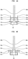
FIGS. 4A-4I are highly schematic end views showing various embodiments of leaflet suturing to a commissure point of the stent according to aspects of the present invention; -
FIGS. 5A-5B are highly schematic front elevational views of two embodiments of the leaflets according to aspects of the present invention; and -
FIG. 5C is a highly schematic end view showing an embodiment of leaflet suturing to a commissure point according to an aspect of the present invention. - As used herein, the term "proximal," when used in connection with a prosthetic heart valve, refers to the end of the heart valve closest to the heart when the heart valve is implanted in a patient, whereas the term "distal," when used in connection with a prosthetic heart valve, refers to the end of the heart valve farthest from the heart when the heart valve is implanted in a patient.
- As seen in
FIG. 1 , a collapsibleprosthetic heart valve 100 typically includes a stent orframe 102 supporting avalve assembly 104. Examples of collapsible prosthetic heart valves are described inInternational Patent Application Publication No. WO/2009/042196 ;United States Patent No. 7,018,406 ;United States Patent No. 7,329,278 ,United States Patent Application Publication Nos. 2005/0113910 and2009/0030511 , the disclosures of all of which are hereby incorporated herein by reference. - The
prosthetic heart valve 100 is designed to replace the function of a native aortic valve of a patient. As discussed in detail below, the prosthetic heart valve has an expanded condition and a collapsed condition. Although the invention is described herein as applied to a prosthetic heart valve for replacing a native aortic valve, the invention is not so limited, and may be applied to prosthetic valves for replacing other types of cardiac valves. - The
prosthetic heart valve 100 includes a stent orframe 102, which may be wholly or partly formed of any biocompatible material, such as metals, synthetic polymers, or biopolymers capable of functioning as a stent. Suitable biopolymers include, but are not limited to, elastin, and mixtures or composites thereof. Suitable metals include, but are not limited to, cobalt, titanium, nickel, chromium, stainless steel, and alloys thereof, including nitinol. Suitable synthetic polymers for use as a stent include, but are not limited to, thermoplastics, such as polyolefins, polyesters, polyamides, polysulfones, acrylics, polyacrylonitriles, polyetheretherketone (PEEK), and polyaramides. Thestent 102 may have anannulus section 110 and an aortic section (not shown). Each of theannulus section 110 and the aortic section of thestent 102 includes a plurality ofcells 112 connected to one another around the stent. Theannulus section 110 and the aortic section of thestent 102 may include one or more annular rows ofcells 112 connected to one another. For instance, theannulus section 110 may have two annular rows ofcells 112. When theprosthetic heart valve 100 is in the expanded condition, eachcell 112 may be substantially diamond shaped. Regardless of its shape, eachcell 112 is formed by a plurality ofstruts 114. For example, acell 112 may be formed by fourstruts 114. - The
stent 102 may include commissure points 116 connecting at least twocells 112 in the longitudinal direction of thestent 102. The commissure points 116 may include eyelets for facilitating the suturing of avalve assembly 104 to thestent 102. - The
prosthetic heart valve 100 also includes avalve assembly 104 attached inside theannulus section 110 of thestent 102.United States Patent Application Publication Nos. 2008/0228264, filed March 12, 2007 ;2008/0147179, filed December 19, 2007 ;2005/0113910, filed July 10, 2004 ; and2009/0030511, filed January 29, 2009 , the entire disclosures of all of which are hereby incorporated herein by reference, describe suitable valve assemblies. Thevalve assembly 104 may be wholly or partly formed of any suitable biological material or polymer materials in the forms of sheets, non-woven and woven fabrics and the like. Examples of biological materials suitable for thevalve assembly 104 include, but are not limited to, porcine or bovine pericardial tissue. Examples of polymers suitable for thevalve assembly 104 include, but are not limited to, polyurethane and polyester. - The
valve assembly 104 may include acuff 106 disposed on the lumenal surface ofannulus section 110, on the ablumenal surface ofannulus section 110, or on both surfaces, and the cuff may cover all or part of either or both of the lumenal and ablumenal surfaces of the annulus section.FIG. 1 showscuff 106 disposed on the lumenal surface ofannulus section 110 so as to cover part of the annulus section while leaving another part thereof uncovered. Thevalve assembly 104 may further include a plurality ofleaflets 108 which collectively function as a one-way valve. Afirst edge 122 of eachleaflet 108 may be attached to thestent 102 by any suitable attachment means, such as suturing, stapling, adhesives or the like. A second orfree edge 124 of eachleaflet 108 may coapt with the corresponding free edges of the other leaflets, thereby enabling the leaflets to function collectively as a one-way valve. - Irrespective of the attachment means employed, the
leaflets 108 may be attached to thestent 102 along at least somestruts 114 of thestent 102 to enhance the structural integrity of thevalve assembly 104. As a consequence of this attachment, thestruts 114 help support theleaflets 108 of thevalve assembly 104 and may therefore reduce the strain in the leaflets. - As shown in
FIG. 1 , at least oneleaflet 108 may be attached to thestent 102 so that itsfirst edge 122 is disposed substantially alongspecific struts annulus section 110 of the stent. That is, theedge 122 is positioned in substantial alignment withstruts edge 122 can be roughly parallel to the edge of thecuff 106. However, of course, thecuff 106 need not be cut to follow the slope or pattern of the struts.Struts cells 112, beginning with an end of thestrut 114a connected to acommissure point 116 and ending with an end ofstrut 114c connected to an end ofstrut 114d.Struts same cell 112 and may collectively define a substantially right angle between them.Struts cells 112, beginning with an end of thestrut 114f connected to acommissure point 116 and ending with the connection between an end ofstrut 114c and an end ofstrut 114d. - As discussed above, the
leaflets 108 may be attached directly to and supported by thestruts cuff 106 may perform little or no supportive function for theleaflets 108, and the thickness of thecuff 106 may, therefore, be reduced. Reducing the thickness of thecuff 106 results in a decrease in the volume of thevalve assembly 104 in the collapsed condition. This decreased volume is desirable as it enables theprosthetic heart valve 100 to be implanted in a patient using a delivery device that is smaller than conventional delivery devices. In addition, since the material forming thestent 114 is stronger than the material forming thecuff 106, the stent may perform the supportive function for theleaflets 108 better than the cuff. - The volume of the
valve assembly 104 may be further reduced by having thecuff 106 cover only a portion of the surface ofannulus section 110. With continued reference toFIG. 3 , the first orproximal end 118 of thecuff 106 may substantially follow the contour of the first orproximal end 119 of thestent 102. As such, the proximal end of thecuff 106 may have a generally sinusoidal or zigzag shape. This eliminates any free edge of thecuff 106, which otherwise might extend directly between the cusps of thecells 112 at theproximal end 119 of thestent 102, and enables the entire length of theproximal end 118 of thecuff 106 to be secured to thestent 102. The second ordistal end 120 of thecuff 106, on the other hand, may be disposed substantially along at least somestruts 114, but not necessarily the struts in a single annular row ofcells 112. - More particularly, the
distal end 120 of thecuff 106 may follow the stent struts 114 up to the commissure points 116, such that thecuff 106 covers all of thecells 112 in the bottomannular row 113 ofcells 112 and in a secondannular row 115 of cells located between the commissure points and theproximal end 119 of thestent 102, but covers a lesser area of cells in the annular regions between the commissure points. In other words, thedistal end 120 of thecuff 106 may be disposed substantially along struts 114a, 114b, 114e, 114f, 114g and 114h, as shown inFIG. 1 .Strut 114g may be connected at one end to strut 114h, and at the other end to the intersection ofstruts Strut 114h may be connected at one end to strut 114g, and at the other end to the intersection ofstruts Struts single cell 112. - As a result of the foregoing configuration, all of the
cells 112 in the bottomannular row 113 ofcells 112 may be entirely covered by thecuff 106. Thecuff 106 may also entirely cover thosecells 112 in the secondannular row 115 that are located directly below the commissure points 116. All of theother cells 112 in thestent 102 may be open or not covered by thecuff 106. Hence, there may be nocells 112 which are only partially covered by thecuff 106. - Since the edges of the
valve leaflets 108 extend up to the secondannular row 115 ofcells 112 only in the regions of the commissure points 116, there is little to no likelihood of leakage in the area of the cells between the commissure points in the second annular row of cells, and therefore no need for thecuff 106 to cover this area. This reduction in the area of thecuff 106, both at theproximal end 118 and at thedistal end 120 thereof, reduces the amount of material in thevalve assembly 104, thereby enabling theprosthetic valve 100 to achieve a smaller cross-section in the collapsed condition. - With reference to
FIG. 2 , aprosthetic heart valve 300 according to another embodiment of the present invention includes a stent orframe 302, which may be similar tostent 102. Thestent 302 may include anaortic section 340 and anannulus section 310. Each of theaortic section 340 and theannulus section 310 may include a plurality ofcells 312 connected to one another in one or more annular rows. Thecells 312 of theaortic section 340 may be larger than the cells of theannulus section 310. Eachcell 312 is formed by a plurality ofstruts 314. For example, eachcell 312 may be formed by fourstruts 314 and may be substantially diamond-shaped when thestent 302 is in an expanded condition. Thestent 302 may further include one or more commissure points 316 for facilitating suturing of avalve assembly 304 to the stent. Eachcommissure point 316 may interconnect twocells 312 in the same annular row and two cells in different annular rows. - The
valve assembly 304 may be attached inside thestent 302, and may include acuff 306 and a plurality ofleaflets 308 which collectively function as a one-way valve. Thecuff 306 may be located on the inside surface of thestent 302, on the outside surface of the stent, or on both the inside surface and the outside surface. Eachleaflet 308 includes anedge 322 attached to thestent 302 and a second free edge 324. Anupper portion 328 of theedge 322 may be attached to thestent 302 so as to be disposed substantially along the path ofcertain struts 314 that lead to the commissure points 316. For example, anupper portion 328 of theedge 322 of at least oneleaflet 308 may be attached to, and disposed substantially along, struts 314a and 314b, and anupper portion 328 of theedge 322 of anadjacent leaflet 308 may be attached to, and disposed substantially along, struts 314c and 314d. As such, struts 314a, 314b, 314c, and 314d help support theseadjacent leaflets 308. Theupper portions 328 of theedges 322 ofadjacent leaflets 308 may be attached to thecommissure point 316 andstruts 314d using sutures 350.Struts commissure point 316 and each may be part of thesame cell 312. - Alternatively, struts 314b and 314c may be attached directly to one another.
Struts different cells 312 that are adjacent to one another. Similarly, struts 314c and 314d may be connected in an end-to-end fashion, and may be part ofdifferent cells 312 that are adjacent to one another. - With reference to
FIG. 3 , a collapsibleprosthetic heart valve 400 according to an embodiment of the present invention includes astent 402, which may be similar tostent 102. Thestent 402 has collapsed and expanded conditions and includes a plurality ofcells 412 connected to one another in annular rows around thestent 402. Eachcell 412 is formed by a plurality ofstruts 414 and may be substantially diamond shaped when thestent 402 is in the expanded condition. For example, onecell 412 may be formed by fourinterconnected struts 414. - The
stent 402 may further include one or more commissure points 416 that interconnect twoadjacent cells 412 located in one annular row and twoother cells 412 located in the next adjacent rows above and below the one row. The commissure points 416 may facilitate the suturing of avalve assembly 404 to thestent 402. - The
valve assembly 404 may include acuff 406 attached to the interior and/or exterior of thestent 402. In addition to thecuff 406, thevalve assembly 404 includes a plurality ofleaflets 408 attached to thestent 402 and collectively defining a one-way valve. Eachleaflet 408 includes afirst edge 422 attached to thestent 402 and a second free edge 424. At least oneleaflet 408 may be attached to thestent 402 so that theupper portions 428 of itsedge 422 are substantially disposed along the path ofcertain struts 414. - As shown in
FIGS. 3 , oneupper portion 428 of theedge 422 of oneleaflet 408 may be connected to acommissure point 416 and may be disposed along and connected to astrut 414b spaced from the commissure point. A section A of theupper portion 428 of theedge 422 may follow a substantially direct path between thecommissure point 416 and an end ofstent strut 414b. Similarly, oneupper portion 428 of theedge 422 of anotherleaflet 408 may be connected to thecommissure point 416 and may be disposed along and connected to astrut 414d spaced from the commissure point. A section A of theupper portion 428 of theedge 422 of thissecond leaflet 408 may follow a substantially direct path between thecommissure point 416 and an end ofstent strut 414d. Theedges 422 of theleaflets 408 may be connected to thecommissure point 416 and to thestruts - In operation, any of the embodiments of the prosthetic heart valve described above may be used to replace a native heart valve, such as the aortic valve. The prosthetic heart valve may be delivered to the desired site (e.g., near a native valve annulus) using any suitable delivery device known in the art. During delivery, the prosthetic heart valve is disposed inside the delivery device in the collapsed condition. The delivery device may be introduced into a patient using the transfemoral, transapical or transseptal approach. Once the delivery device has reached the target site, the user may deploy any of the prosthetic heart valves described above. Upon deployment, the prosthetic heart valve expands into secure engagement within the native valve annulus. When the prosthetic heart valve is properly positioned inside the heart, it works as a one-way valve, allowing blood to flow in one direction and preventing blood from flowing in the opposite direction.
- In each of the prosthetic heart valve embodiments described above, the valve assembly preferably is spaced from the distal or aortic end of the stent by a distance that enables deployment of the heart valve by an amount sufficient for the valve leaflets of the prosthetic valve to operate as intended, while the distal end of the stent remains captured by the delivery device. More particularly, the annulus end of the prosthetic heart valve may be deployed first while the aortic end of the prosthetic heart valve remains at least partially covered by the distal sheath of the delivery device. The annulus portion of the prosthetic heart valve may be deployed so that the entirety of the valve leaflets, up to and including the commissures, is deployed and fully operational. By deploying the prosthetic heart valve in this manner, the user can determine whether the valve leaflets are properly positioned relative to the native valve annulus, and whether the valve is functioning properly.
- If the user determines that the positioning and operation of the valve are acceptable, the remainder of the valve may be deployed. However, if it is determined that the leaflet position is improper or that the valve is not functioning properly, the user may resheath the valve and either reposition it for redeployment, or remove it entirely from the patient. This can be particularly important in very high risk patients who would typically be recipients of these types of valves, because of the nature of their condition and the impact that may have on the shape and/or condition of the native valve and valve annulus. Of course, the prosthetic heart valve of the present invention can be delivered by deploying the aortic or distal end first as well.
- Anatomical irregularities at the implantation site can create issues with respect to the proper functioning and wear of the prosthetic heart valve. Another aspect of the invention is the achievement of a better functioning valve in the various shapes, such as elliptical, round, irregular, etc., that the valve may assume upon implantation and use. This may depend, in some instances, not only on leaflet positioning, commissure positioning, and valve geometry, as previously described, but also can relate to the manner in which the leaflets are attached to the valve assembly, the stent, and in particular, the commissure attachment points. As the stent is deformed by implantation and use, if leaflet positioning and geometry are not correct, undesirable load forces at the leaflet edges, particularly at the commissure attachment points, can be created. This can lead to tearing of the leaflets and/or cuff and eventually valve failure.
- Some arrangements that are intended to minimize valve failure and promote better valve function are illustrated in
FIGS. 4A-4I. FIGS. 4A-4I show various arrangements for attaching the leaflets to the commissure points 116 in order to promote better and longer valve function. Which particular arrangement is used may depend, inter alia, on the type of valve material used, the thickness of the stent, the dimensions of the commissure points, the type, thickness and placement of the cuff, if any, the overall shape of the valve and valve assembly, and the like. Note that in the various illustrations which represent the end views, as seen from the distal end of the stent along the longitudinal axis of the stent toward the proximal end of the stent, of a commissure point and the attachment of the leaflets thereto (in which the dashed lines represent suture lines), the cuff is not illustrated for purposes of clarity. - Referring to
FIG. 4A , portions of twoadjacent leaflets leaflets adjacent leaflets commissure point 116. In the illustrated embodiment, anend portion 722a ofleaflet 108a is folded in a generally "U-shaped"pleat 737a. Likewise, anend portion 722b ofleaflet 108b is folded in a generally "U-shaped"pleat 737b. The foldedend portions adjacent portions leaflets commissure point 116. The foldedend portions end portion 722a may be sutured tocommissure point 116 via one ormore sutures 720a andend portion 722b may be sutured tocommissure point 116 via one ormore sutures 720b (a single suture illustrated). Since thesutures U-shaped pleats leaflet -
FIG. 4B illustrates the suturing of the leaflets to thecommissure point 116 according to another embodiment of the invention. Each of theend portions respective leaflets pleat FIG. 4A , and theU-shaped pleats adjacent portions leaflets commissure point 116. TheU-shaped pleat 737a may be sutured to thecommissure point 116 via one ormore sutures 730a. Similarly, theU-shaped pleat 737b may be sutured to thecommissure point 116 via one ormore sutures 730b. In variants hereof, less than or more than two sutures may be employed to suture each foldedend portion commissure point 116. Sincesutures U-shaped pleats leaflets -
FIG. 4C illustrates a variant of the embodiment ofFIG. 4B . In the embodiment ofFIG. 4C , theend portions free edges adjacent portions leaflets U-shaped pleats free edges end portions - Referring to
FIG. 4D , the embodiment illustrated is generally similar to the embodiments ofFIGS. 4B and4C . Whereas in the embodiments ofFIGS. 4B and4C , theend portions leaflets U-shaped pleats end portions FIG. 4D include multiple folds in a generally compressed "S-shaped" pleat or aHeintz pleat FIG. 4D for thepleats FIG. 4D further distribute the stresses due to suturing and reduce the likelihood of tearing theleaflets - Now referring to
FIG. 4E ,leaflets commissure point 116 according to another embodiment of the invention. Theend portion 722a ofleaflet 108a is wrapped around one side ofcommissure point 116 such that aU-shaped pleat 735a is formed, which generally envelopes one side of the commissure point. Likewise, theend portion 722b ofleaflet 108b is wrapped around the other side ofcommissure point 116 such that aU-shaped pleat 735b is formed, which generally envelopes the other side of the commissure point. Thus, thecommissure point 116 may be enveloped on opposing sides by theend portions more sutures 730a (one pair of suture illustrated) attach theend portion 722a to thecommissure point 116, and one ormore sutures 730b (one pair of suture illustrated) attach theend portion 722b to thecommissure point 116. The suturing sites on theend portions commissure point 116, thereby reducing the stress due to suturing in theleaflets cuff 106 is attached. It could be attached on the ablumenal surface over the free ends 724a, 724b. In other configurations, thecuff 106 could also be split in the proximity of thecommissure point 116 so that either end may be attached over the top of the inner portion of the folds. - The
cuff 106 could also be attached to the lumenal surface but disposed between and under the commissure points and the proximal end of the stent. These types of cuff arrangements may also be used in connection with, for example, the embodiments illustrated inFIGS. 4F and4G . -
FIG. 4F illustrates an embodiment which generally includes the features of the embodiment illustrated inFIG. 4E . In particular, theend portion 722a of theleaflet 108a is wrapped around one side ofcommissure point 116 such that aU-shaped pleat 735a is formed which envelopes one side of thecommissure point 116. Theend portion 722b of theleaflet 108b is wrapped around the other side of the commissure point such that aU-shaped pleat 735b is formed which envelopes the other side of thecommissure point 116. A tissue orfabric web 750 is then wrapped around theend portions commissure point 116 from the outside surface (the bottom as seen inFIG. 4F ) so as to cover any gap between the free ends 724a and 724b. One ormore sutures leaflet web 750 and theend portions commissure point 116. In an exemplary configuration, theweb 750 may be formed from any suitable biological material or polymer. Examples of biological materials suitable for theweb 750 include, but are not limited to, porcine or bovine pericardial tissue. Examples of polymers suitable for theweb 750 include, but are not limited to, polyurethane and polyester. Theweb 750 provides reinforcement to theend portions - In yet another embodiment illustrated in
FIG. 4G , which is a variation of the embodiment illustrated inFIG. 4F , theend portions respective leaflets commissure point 116 in an L-shaped fold, but do not wrap around the same. A fabric ortissue web 751 is then wrapped around thecommissure point 116 so as to overlie theend portions leaflets web 751 may be formed from the same materials as may be used for forming theweb 750. One ormore sutures 730a (one pair of sutures illustrated) may attach theweb 751 and theend portion 722a to thecommissure point 116. Likewise, one ormore sutures 730b (one pair of sutures illustrated) may attach theweb 751 and theend portion 722b to thecommissure point 116. Theweb 751 provides reinforcement to theend portions - Referring now to
FIG. 4H ,leaflets commissure point 116 according to yet another embodiment of the invention. Theend portions respective leaflets spiral configuration rolled end portions commissure point 116 via one ormore sutures rolled end portions sutures end portions - FIG. 41 illustrates another exemplary embodiment of the invention. Each of the
end portions respective leaflets pleat cuff 706 is interposed between theU-shaped pleats commissure point 116. The free ends 724a, 724b of therespective end portions leaflets fabric webs end portions webs web 750. One ormore sutures 730a attach the foldedend portion 722a along with theweb 760a and thecuff 706 to thecommissure point 116, while one ormore sutures 730b attach the foldedend portion 722b along with theweb 760b and thecuff 706 to the commissure point. Thewebs portions -
FIG. 5A schematically illustrates theleaflet 108, which may be sutured to thecommissure point 116 of thestent 102 using any of the configurations described above.Leaflet 108 has afree edge 505 and anarcuate edge 507 attached, for example, to one ormore struts 114 of thestent 102 as described above. Leaflet 108 may include a generallyrectangular tab 510 at one end of thefree edge 505 and another generallyrectangular tab 520 at the other end of thefree edge 505. Thetab 510 may be defined by a substantially straightoutside edge 511, a substantially straightinside edge 512, that is substantially parallel to theedge 511, a substantially straighttop edge 513, and a substantially straightbottom edge 514, that is substantially parallel to thetop edge 513 and substantially orthogonal to theedges tab 510 may include afurther projection 530 projecting laterally from theoutside edge 511. Thetab 520 may be substantially the same thetab 510, but may omit thefurther projection 530. - As noted, the
leaflet 108 may be attached to thecommissure point 116 of thestent 102 using any of the configurations previously described. The following will describe the attachment of theleaflet 108 to thecommissure point 116 using the configuration of FIG. 41. Thetab 510 may include animaginary fold line 532, which is generally aligned with thearcuate edge 507 of theleaftlet 108, and is substantially parallel to theedges tab 510 into afirst portion 542 and asecond portion 544. Thetab 510 may be folded along thefold line 532 to form, for example, the generally "U-shaped"pleat 737a shown in FIG. 41. -
FIGS. 5B and5C illustrate yet another embodiment of theleaflet 108 and the suturing of the leaflet to thecommissure point 116. Theleaflet 108 may be generally similar to theleaflet 108 ofFIG. 5A , except for the differences set forth below. Theleaflet 108 may include a generallyrectangular tab 610, similar in configuration to thetab 510 ofFIG. 5A , extending from one end of thefree edge 505, and a similar generallyrectangular tab 640 extending from the other end of thefree edge 505. Rather than having a further projection extending from the outside edge as withtab 510, however thetab 610 may optionally have afurther projection 630 extending from the top edge 613. A similarfurther projection 650 may extend from the top edge of thetab 640. - As noted, the
leaflet 108 may be attached to thecommissure point 116 of thestent 102 using any of the configurations previously described. Yet another configuration for attaching theleaflet 108 to thecommissure point 116 is shown inFIG. 5C . Thetab 610 may include animaginary fold line 632, which is generally aligned with thearcuate edge 507 of theleaflet 108 and one edge offurther projection 630, and is substantially parallel to theoutside edge 611 and theinsdie edge 612 oftab 610, dividing thetab 610 into afirst portion 642 and asecond portion 644. A generallyvertical slit 620, as seen inFIG. 5B , is defined in thefirst portion 642 of thetab 610 and is substantially parallel to theedges tab 610 may be folded along thefold line 632 to form a generally "U-shaped"pleat 637 which extends acrossleaflets slit 620 accommodates portions of the free edges of theleaflets more sutures 730a attach the foldedsecond portion 644 of theleaflet 108b and thefree end 722a of theleaflet 108a to thecommissure point 116. One ormore sutures 730b attach theU-shaped pleat 637 to thecommissure point 116. Where thetab 610 includesfurther projection 630, the further projection may be tacked to the stent and then later removed. - Although the invention herein has been described with reference to particular embodiments, it is to be understood that these embodiments are merely illustrative of the principles and applications of the present invention. It is therefore to be understood that numerous modifications may be made to the illustrative embodiments and that other arrangements may be devised without departing from the spirit and scope of the present invention as defined by the appended claims.
- It will be appreciated that the various dependent claims and the features set forth therein can be combined in different ways than presented in the initial claims. It will also be appreciated that the features described in connection with individual embodiments may be shared with others of the described embodiments.
- The present invention enjoys wide industrial applicability including, but not limited to, medical devices and methods for heart valve replacement, and in particular, to collapsible prosthetic heart valves.
- The following Paragraphs summarize certain aspects of the disclosure.
- Paragraph A: A prosthetic heart valve, comprising a collapsible and expandable stent having a proximal end and a distal end, a plurality of commissure points disposed on the stent; and a collapsible and expandable valve assembly disposed within the stent, the valve assembly including a plurality of leaflets, each leaflet having a free edge, wherein an end portion of the free edge of one leaflet includes a folded portion, the folded portion being sutured to one of the plurality of commissure points.
- Paragraph B: the end portions of the free edges of first and second adjacent leaflets are sutured to one another.
- Paragraph C: The end portion of the free edge of an adjacent leaflet includes a folded portion, the folded portion of the adjacent leaflet being sutured to the one commissure point.
- Paragraph D: The prosthetic heart valve further comprises a reinforcement web disposed between the folded portions of the one leaflet and the adjacent leaflet.
- Paragraph E: The folded portion of the one leaflet and the folded portion of the adjacent leaflet each wrap at least partially around the one commissure point, the prosthetic heart valve further comprising a web of material overlying the folded portions of the leaflets, the web of material being sutured to both the folded portions of the leaflets and the one commissure point.
- Paragraph F: The folded portion is generally parallel to a remainder of the end portion of the one leaflet.
- Paragraph G: The folded portion is generally perpendicular to a remainder of the end portion of the one leaflet.
- Paragraph H: The free end of the folded portion extends beyond the suture toward a remainder of the end portion of the one leaflet.
- Paragraph I: The folded portion includes at least two layers of the end portion of the one leaflet.
- Paragraph J: The folded portion is in the form of a spiral.
- Paragraph K: The folded portion wraps at least partially around the one commissure point.
- Paragraph L: The prosthetic heart further comprises a web of material overlying the folded portion, the web of material being sutured to the folded portion and the one commissure point.
- Paragraph M: A prosthetic heart valve, comprising: a collapsible and expandable stent having a proximal end and a distal end, a plurality of commissure points disposed on the stent and a collapsible and expandable valve assembly disposed within the stent, the valve assembly including a plurality of leaflets, each leaflet having a free edge, wherein an end portion of the free edge of one leaflet includes a folded portion, the folded portion being sutured to one of the plurality of commissure points, the folded portion having a configuration selected from the group consisting of a U-shaped pleat, an S-shaped pleat, a generally spiral roll and an L-shaped fold.
Claims (12)
- A prosthetic heart valve, comprising:a collapsible and expandable stent (102) having a proximal end and a distal end and comprising a plurality of struts (114) and a plurality of cells (112) defined by the plurality of struts (114);a plurality of commissure points (116) disposed on the stent; anda valve assembly (104) disposed within the stent, the valve assembly including a plurality of leaflets (108), a first edge (122) of each leaflet (108) being attached to the stent (102), and a second or free edge (124) of each leaflet (108) configured to coapt with corresponding free edges (124) of the other leaflets (108) to function collectively as a one-way valve, an adjacent pair of the leaflets (108a, 108b) having ends portion (722a, 722b) with free edges (724a, 724b);characterised in that each of the end portions (722a, 722b) is folded in a generally U-shaped pleat (737a, 737b) that is bent outwardly so as to lie substantially perpendicular to immediate adjacent portions (735a, 735b) of the leaflets (108a, 108b) and generally parallel to a corresponding one of the commissure points (116), each U-shaped pleat (737a, 737b) being sutured to the corresponding one of the commissure points (116) via one or more sutures (730a).
- The prosthetic heart valve of claim 1, wherein each U-shaped pleat (737a, 737b) is sutured to the corresponding one of the commissure points (116) via two sutures (730a).
- The prosthetic heart valve of claim 1 or 2, wherein the free edge (724a, 724b) of each end portion (722a, 722b) are unsutured.
- The prosthetic heart valve of claim 3, wherein the free edge (724a, 724b) of each end portion (722a, 722b) extends toward the immediate adjacent portions (735a, 735b).
- The prosthetic heart valve of claim 4, wherein the free edge (724a, 724b) of each end portion (722a, 722b) curls back toward the U-shaped pleat (737a, 737b).
- The prosthetic heart valve of any of claims 1-3, further comprising a cuff (706) interposed between the U-shaped pleats (737a, 737b) and the commissure point (116).
- The prosthetic heart valve of any of claims 1-3, wherein the free edge (724a, 724b) of each end portion (722a, 722b) is attached to the immediate adjacent portion (735a, 735b) of the leaflets (108a, 108b).
- The prosthetic heart valve of any of claims 1-3, further comprising reinforcement tissue or fabric webs (760a, 760b) disposed between folds of each of the end portions (722a, 722b).
- The prosthetic heart valve of any of the preceding claims, wherein prior to assembly of the prosthetic heart valve, each leaflet (108) includes a generally rectangular tab (510) at one end of the free edge (124, 505) of the leaflet (108) and another generally rectangular tab (520) at the other end of the free edge (124, 505) of the leaflet (108).
- The prosthetic heart valve of claim 9, wherein the generally rectangular tab (510) at the one end of the free edge (124, 505) of the leaflet (108) is defined by a substantially straight outside edge (511), a substantially straight inside edge (512) that is substantially parallel to the outside edge (511), a substantially straight top edge (513), and a substantially straight bottom edge (514) that is substantially parallel to the top edge (513) and substantially orthogonal to the outside edge (511) and the inside edge (512).
- The prosthetic heart valve of claim 10, wherein the generally rectangular tab (510) at the one end of the free edge (124, 505) of the leaflet (108) includes a projection (530) projecting laterally from the outside edge (511).
- The prosthetic heart valve of claim 11, wherein the generally rectangular tab (520) at the other end of the free edge (124, 505) of the leaflet (108) is substantially the same as the generally rectangular tab (510) at the one end of the free edge (124, 505) except that it omits the projection (530).
Applications Claiming Priority (4)
| Application Number | Priority Date | Filing Date | Title |
|---|---|---|---|
| US201161438451P | 2011-02-01 | 2011-02-01 | |
| US13/216,124 US9717593B2 (en) | 2011-02-01 | 2011-08-23 | Leaflet suturing to commissure points for prosthetic heart valve |
| PCT/US2011/048967 WO2012106011A1 (en) | 2011-02-01 | 2011-08-24 | Leaflet suturing to commissure point for prosthetic heart valve |
| EP11857681.8A EP2670351B2 (en) | 2011-02-01 | 2011-08-24 | Leaflet suturing to commissure points for prosthetic heart valve |
Related Parent Applications (2)
| Application Number | Title | Priority Date | Filing Date |
|---|---|---|---|
| EP11857681.8A Division EP2670351B2 (en) | 2011-02-01 | 2011-08-24 | Leaflet suturing to commissure points for prosthetic heart valve |
| EP11857681.8A Division-Into EP2670351B2 (en) | 2011-02-01 | 2011-08-24 | Leaflet suturing to commissure points for prosthetic heart valve |
Publications (2)
| Publication Number | Publication Date |
|---|---|
| EP4140446A1 true EP4140446A1 (en) | 2023-03-01 |
| EP4140446B1 EP4140446B1 (en) | 2026-03-11 |
Family
ID=52574864
Family Applications (2)
| Application Number | Title | Priority Date | Filing Date |
|---|---|---|---|
| EP11857681.8A Active EP2670351B2 (en) | 2011-02-01 | 2011-08-24 | Leaflet suturing to commissure points for prosthetic heart valve |
| EP22184311.3A Active EP4140446B1 (en) | 2011-02-01 | 2011-08-24 | Leaflet suturing to commissure points for prosthetic heart valve |
Family Applications Before (1)
| Application Number | Title | Priority Date | Filing Date |
|---|---|---|---|
| EP11857681.8A Active EP2670351B2 (en) | 2011-02-01 | 2011-08-24 | Leaflet suturing to commissure points for prosthetic heart valve |
Country Status (8)
| Country | Link |
|---|---|
| US (5) | US9717593B2 (en) |
| EP (2) | EP2670351B2 (en) |
| JP (1) | JP6276994B2 (en) |
| AU (2) | AU2011357688B2 (en) |
| BR (1) | BR112013019558A2 (en) |
| CR (1) | CR20130396A (en) |
| ES (1) | ES2928491T5 (en) |
| WO (1) | WO2012106011A1 (en) |
Families Citing this family (90)
| Publication number | Priority date | Publication date | Assignee | Title |
|---|---|---|---|---|
| DE102005003632A1 (en) | 2005-01-20 | 2006-08-17 | Fraunhofer-Gesellschaft zur Förderung der angewandten Forschung e.V. | Catheter for the transvascular implantation of heart valve prostheses |
| US7896915B2 (en) | 2007-04-13 | 2011-03-01 | Jenavalve Technology, Inc. | Medical device for treating a heart valve insufficiency |
| WO2011104269A1 (en) | 2008-02-26 | 2011-09-01 | Jenavalve Technology Inc. | Stent for the positioning and anchoring of a valvular prosthesis in an implantation site in the heart of a patient |
| US9044318B2 (en) | 2008-02-26 | 2015-06-02 | Jenavalve Technology Gmbh | Stent for the positioning and anchoring of a valvular prosthesis |
| US8579964B2 (en) | 2010-05-05 | 2013-11-12 | Neovasc Inc. | Transcatheter mitral valve prosthesis |
| US10856978B2 (en) | 2010-05-20 | 2020-12-08 | Jenavalve Technology, Inc. | Catheter system |
| CA2799459A1 (en) | 2010-05-25 | 2011-12-01 | Jenavalve Technology Inc. | Prosthetic heart valve and transcatheter delivered endoprosthesis comprising a prosthetic heart valve and a stent |
| WO2012026965A2 (en) | 2010-08-24 | 2012-03-01 | St. Jude Medical, Inc. | Staged deployment devices and methods for transcatheter heart valve delivery systems |
| US9039759B2 (en) | 2010-08-24 | 2015-05-26 | St. Jude Medical, Cardiology Division, Inc. | Repositioning of prosthetic heart valve and deployment |
| WO2012036741A2 (en) | 2010-09-17 | 2012-03-22 | St. Jude Medical, Cardiology Division, Inc. | Staged deployment devices and methods for transcatheter heart valve delivery |
| AU2011306028B2 (en) | 2010-09-20 | 2014-07-17 | St. Jude Medical, Cardiology Division, Inc. | Valve leaflet attachment in collapsible prosthetic valves |
| RS61073B1 (en) | 2010-10-05 | 2020-12-31 | Edwards Lifesciences Corp | Prosthetic heart valve |
| US9717593B2 (en) | 2011-02-01 | 2017-08-01 | St. Jude Medical, Cardiology Division, Inc. | Leaflet suturing to commissure points for prosthetic heart valve |
| US8932343B2 (en) * | 2011-02-01 | 2015-01-13 | St. Jude Medical, Cardiology Division, Inc. | Blunt ended stent for prosthetic heart valve |
| WO2012127309A1 (en) | 2011-03-21 | 2012-09-27 | Ontorfano Matteo | Disk-based valve apparatus and method for the treatment of valve dysfunction |
| US9308087B2 (en) | 2011-04-28 | 2016-04-12 | Neovasc Tiara Inc. | Sequentially deployed transcatheter mitral valve prosthesis |
| US9554897B2 (en) | 2011-04-28 | 2017-01-31 | Neovasc Tiara Inc. | Methods and apparatus for engaging a valve prosthesis with tissue |
| US9060860B2 (en) | 2011-08-18 | 2015-06-23 | St. Jude Medical, Cardiology Division, Inc. | Devices and methods for transcatheter heart valve delivery |
| US9345573B2 (en) | 2012-05-30 | 2016-05-24 | Neovasc Tiara Inc. | Methods and apparatus for loading a prosthesis onto a delivery system |
| US9615920B2 (en) | 2012-06-29 | 2017-04-11 | St. Jude Medical, Cardiology Divisions, Inc. | Commissure attachment feature for prosthetic heart valve |
| US20140005776A1 (en) * | 2012-06-29 | 2014-01-02 | St. Jude Medical, Cardiology Division, Inc. | Leaflet attachment for function in various shapes and sizes |
| US9681951B2 (en) | 2013-03-14 | 2017-06-20 | Edwards Lifesciences Cardiaq Llc | Prosthesis with outer skirt and anchors |
| US9326856B2 (en) | 2013-03-14 | 2016-05-03 | St. Jude Medical, Cardiology Division, Inc. | Cuff configurations for prosthetic heart valve |
| US8870948B1 (en) | 2013-07-17 | 2014-10-28 | Cephea Valve Technologies, Inc. | System and method for cardiac valve repair and replacement |
| CN105491978A (en) * | 2013-08-30 | 2016-04-13 | 耶拿阀门科技股份有限公司 | Radially collapsible frame for a prosthetic valve and method for manufacturing such a frame |
| CN111419472B (en) * | 2013-11-11 | 2023-01-10 | 爱德华兹生命科学卡迪尔克有限责任公司 | System and method for manufacturing stent frames |
| US9549818B2 (en) | 2013-11-12 | 2017-01-24 | St. Jude Medical, Cardiology Division, Inc. | Pneumatically power-assisted tavi delivery system |
| EP4527350A3 (en) | 2013-12-19 | 2025-06-18 | St. Jude Medical, Cardiology Division, Inc. | Leaflet-cuff attachments for prosthetic heart valve |
| EP4091581B1 (en) * | 2014-02-18 | 2023-12-27 | Edwards Lifesciences Corporation | Flexible commissure frame |
| EP2918247A1 (en) * | 2014-03-11 | 2015-09-16 | Epygon Sasu | A prosthetic valve and a delivery device |
| JP6411043B2 (en) * | 2014-03-20 | 2018-10-24 | 学校法人東邦大学 | Leaflet template |
| US9610157B2 (en) | 2014-03-21 | 2017-04-04 | St. Jude Medical, Cardiology Division, Inc. | Leaflet abrasion mitigation |
| EP2954875B1 (en) * | 2014-06-10 | 2017-11-15 | St. Jude Medical, Cardiology Division, Inc. | Stent cell bridge for cuff attachment |
| WO2016007652A1 (en) | 2014-07-08 | 2016-01-14 | Avinger, Inc. | High speed chronic total occlusion crossing devices |
| US20160095701A1 (en) * | 2014-10-07 | 2016-04-07 | St. Jude Medical, Cardiology Division, Inc. | Bi-Leaflet Mitral Valve Design |
| EP4306080A3 (en) | 2014-12-09 | 2024-04-10 | Cephea Valve Technologies, Inc. | Replacement cardiac valves and method of manufacture |
| EP3270825B1 (en) | 2015-03-20 | 2020-04-22 | JenaValve Technology, Inc. | Heart valve prosthesis delivery system |
| EP3632378B1 (en) | 2015-05-01 | 2024-05-29 | JenaValve Technology, Inc. | Device with reduced pacemaker rate in heart valve replacement |
| WO2016183523A1 (en) | 2015-05-14 | 2016-11-17 | Cephea Valve Technologies, Inc. | Cardiac valve delivery devices and systems |
| EP3294221B1 (en) | 2015-05-14 | 2024-03-06 | Cephea Valve Technologies, Inc. | Replacement mitral valves |
| US9974650B2 (en) * | 2015-07-14 | 2018-05-22 | Edwards Lifesciences Corporation | Prosthetic heart valve |
| DE202016008737U1 (en) | 2015-12-15 | 2019-04-05 | Neovasc Tiara Inc. | Transseptal delivery system |
| CN108882981B (en) | 2016-01-29 | 2021-08-10 | 内奥瓦斯克迪亚拉公司 | Prosthetic valve for preventing outflow obstruction |
| US11065138B2 (en) | 2016-05-13 | 2021-07-20 | Jenavalve Technology, Inc. | Heart valve prosthesis delivery system and method for delivery of heart valve prosthesis with introducer sheath and loading system |
| EP3471665B1 (en) | 2016-06-17 | 2023-10-11 | Cephea Valve Technologies, Inc. | Cardiac valve delivery devices |
| US11096781B2 (en) | 2016-08-01 | 2021-08-24 | Edwards Lifesciences Corporation | Prosthetic heart valve |
| US10575944B2 (en) * | 2016-09-22 | 2020-03-03 | Edwards Lifesciences Corporation | Prosthetic heart valve with reduced stitching |
| CN109996581B (en) | 2016-11-21 | 2021-10-15 | 内奥瓦斯克迪亚拉公司 | Methods and systems for rapid retrieval of transcatheter heart valve delivery systems |
| EP3547964A1 (en) | 2016-12-02 | 2019-10-09 | St. Jude Medical, Cardiology Division, Inc. | Transcatheter delivery system with transverse wheel actuation |
| US10758352B2 (en) | 2016-12-02 | 2020-09-01 | St. Jude Medical, Cardiology Division, Inc. | Transcatheter delivery system with two modes of actuation |
| US10653523B2 (en) | 2017-01-19 | 2020-05-19 | 4C Medical Technologies, Inc. | Systems, methods and devices for delivery systems, methods and devices for implanting prosthetic heart valves |
| CA3051272C (en) | 2017-01-23 | 2023-08-22 | Cephea Valve Technologies, Inc. | Replacement mitral valves |
| AU2018203053B2 (en) | 2017-01-23 | 2020-03-05 | Cephea Valve Technologies, Inc. | Replacement mitral valves |
| US10561495B2 (en) | 2017-01-24 | 2020-02-18 | 4C Medical Technologies, Inc. | Systems, methods and devices for two-step delivery and implantation of prosthetic heart valve |
| CN110392557A (en) | 2017-01-27 | 2019-10-29 | 耶拿阀门科技股份有限公司 | Heart valve simulation |
| US12029647B2 (en) | 2017-03-07 | 2024-07-09 | 4C Medical Technologies, Inc. | Systems, methods and devices for prosthetic heart valve with single valve leaflet |
| EP3624739A1 (en) | 2017-05-15 | 2020-03-25 | St. Jude Medical, Cardiology Division, Inc. | Transcatheter delivery system with wheel actuation |
| US12036113B2 (en) | 2017-06-14 | 2024-07-16 | 4C Medical Technologies, Inc. | Delivery of heart chamber prosthetic valve implant |
| US10898319B2 (en) * | 2017-08-17 | 2021-01-26 | Edwards Lifesciences Corporation | Sealing member for prosthetic heart valve |
| CA3073834A1 (en) | 2017-08-25 | 2019-02-28 | Neovasc Tiara Inc. | Sequentially deployed transcatheter mitral valve prosthesis |
| CA3078607C (en) | 2017-10-31 | 2022-07-26 | W.L. Gore & Associates, Inc. | Valved conduit |
| WO2019147846A2 (en) | 2018-01-25 | 2019-08-01 | Edwards Lifesciences Corporation | Delivery system for aided replacement valve recapture and repositioning post- deployment |
| US11857441B2 (en) | 2018-09-04 | 2024-01-02 | 4C Medical Technologies, Inc. | Stent loading device |
| WO2020093172A1 (en) | 2018-11-08 | 2020-05-14 | Neovasc Tiara Inc. | Ventricular deployment of a transcatheter mitral valve prosthesis |
| US12544226B2 (en) | 2019-02-14 | 2026-02-10 | 4C Medical Technologies, Inc. | Hydrophilic skirt for paravalvular leak mitigation and fit and apposition optimization for prosthetic heart valve implants |
| WO2020185597A1 (en) | 2019-03-08 | 2020-09-17 | Neovasc Tiara Inc. | Retrievable prosthesis delivery system |
| US11045301B2 (en) | 2019-03-12 | 2021-06-29 | Cook Medical Technologies Llc | Implantable medical device with compound stitching connection of framework to fabric |
| US11602429B2 (en) | 2019-04-01 | 2023-03-14 | Neovasc Tiara Inc. | Controllably deployable prosthetic valve |
| CN110123490B (en) * | 2019-04-08 | 2024-07-02 | 北京佰仁医疗科技股份有限公司 | Connecting structure of stent and valve leaflet and interventional pulmonary valve and interventional aortic valve applying connecting structure |
| EP3952792A4 (en) | 2019-04-10 | 2023-01-04 | Neovasc Tiara Inc. | PROSTHETIC VALVE WITH NATURAL BLOOD FLOW |
| US11452628B2 (en) | 2019-04-15 | 2022-09-27 | 4C Medical Technologies, Inc. | Loading systems for collapsible prosthetic heart valve devices and methods thereof |
| EP3972673B1 (en) | 2019-05-20 | 2026-01-28 | Neovasc Tiara Inc. | Introducer with hemostasis mechanism |
| CN114144144B (en) | 2019-06-20 | 2026-01-13 | 内奥瓦斯克迪亚拉公司 | Low-profile prosthetic mitral valve |
| WO2021068788A1 (en) * | 2019-10-08 | 2021-04-15 | 杭州启明医疗器械股份有限公司 | Improved leaflet of cardiac valve, and cardiac valve preform, cardiac valve, and processing method therefor |
| CA3143549A1 (en) * | 2019-10-31 | 2021-05-06 | Edwards Lifesciences Corporation | Prosthetic heart valve leaflet assemblies and methods of assembling |
| EP4065049B1 (en) * | 2020-01-14 | 2024-10-30 | Edwards Lifesciences Corporation | Prosthetic heart valve leaflet assemblies and methods |
| CN113133852A (en) * | 2020-01-17 | 2021-07-20 | 徐冠彪 | Prosthetic valve and method of making same |
| US11931253B2 (en) | 2020-01-31 | 2024-03-19 | 4C Medical Technologies, Inc. | Prosthetic heart valve delivery system: ball-slide attachment |
| US12133797B2 (en) | 2020-01-31 | 2024-11-05 | 4C Medical Technologies, Inc. | Prosthetic heart valve delivery system: paddle attachment feature |
| EP4609835A3 (en) * | 2020-02-06 | 2025-11-19 | Edwards Lifesciences Corporation | Prosthetic heart valve leaflet commissure assemblies and methods |
| US12053375B2 (en) | 2020-03-05 | 2024-08-06 | 4C Medical Technologies, Inc. | Prosthetic mitral valve with improved atrial and/or annular apposition and paravalvular leakage mitigation |
| US11992403B2 (en) | 2020-03-06 | 2024-05-28 | 4C Medical Technologies, Inc. | Devices, systems and methods for improving recapture of prosthetic heart valve device with stent frame having valve support with inwardly stent cells |
| CN113662712B (en) * | 2020-05-14 | 2025-11-28 | 爱德华兹生命科学公司 | Prosthetic heart valve small She Gefeng assembly and method |
| EP4494604A3 (en) * | 2020-07-17 | 2025-04-09 | Edwards Lifesciences Corporation | Commissure assemblies formed from tabs of asymmetric leaflets |
| US12310848B2 (en) * | 2021-02-24 | 2025-05-27 | St. Jude Medical, Cardiology Division, Inc. | Leaflet attachment to prosthetic heart valve |
| US12588998B1 (en) | 2022-09-01 | 2026-03-31 | 4C Medical Technologies, Inc. | Prosthetic heart valve for natural blood flow |
| US12171658B2 (en) | 2022-11-09 | 2024-12-24 | Jenavalve Technology, Inc. | Catheter system for sequential deployment of an expandable implant |
| US20240252312A1 (en) * | 2023-01-27 | 2024-08-01 | Medtronic, Inc. | Reinforced commissure for prosthetic heart valve |
| US20240366366A1 (en) | 2023-03-24 | 2024-11-07 | 4C Medical Technologies, Inc. | Implant delivery |
| CN121041074A (en) * | 2025-10-30 | 2025-12-02 | 成都赛拉诺医疗科技股份有限公司 | A positive torque self-locking mitral valve replacement stent |
Citations (9)
| Publication number | Priority date | Publication date | Assignee | Title |
|---|---|---|---|---|
| US20040186563A1 (en) * | 2003-03-18 | 2004-09-23 | Lobbi Mario M. | Minimally-invasive heart valve with cusp positioners |
| US20050113910A1 (en) | 2002-01-04 | 2005-05-26 | David Paniagua | Percutaneously implantable replacement heart valve device and method of making same |
| US7018406B2 (en) | 1999-11-17 | 2006-03-28 | Corevalve Sa | Prosthetic valve for transluminal delivery |
| US20080147179A1 (en) | 2006-12-19 | 2008-06-19 | St. Jude Medical, Inc. | Prosthetic heart valve including stent structure and tissue leaflets, and related methods |
| US20080228264A1 (en) | 2007-03-12 | 2008-09-18 | St. Jude Medical, Inc. | Prosthetic heart valves with flexible leaflets |
| WO2009042196A2 (en) | 2007-09-26 | 2009-04-02 | St. Jude Medical, Inc. | Collapsible prosthetic heart valves |
| US20090157175A1 (en) * | 2007-12-14 | 2009-06-18 | Edwards Lifesciences Corporation | Leaflet attachment frame for a prosthetic valve |
| US20090240320A1 (en) * | 2008-03-18 | 2009-09-24 | Yosi Tuval | Valve suturing and implantation procedures |
| US20100262231A1 (en) * | 2006-09-19 | 2010-10-14 | Yossi Tuval | Sinus-Engaging Valve Fixation Member |
Family Cites Families (269)
| Publication number | Priority date | Publication date | Assignee | Title |
|---|---|---|---|---|
| US3657744A (en) | 1970-05-08 | 1972-04-25 | Univ Minnesota | Method for fixing prosthetic implants in a living body |
| US4491986A (en) | 1976-05-12 | 1985-01-08 | Shlomo Gabbay | Heart valve |
| US4275469A (en) | 1979-12-13 | 1981-06-30 | Shelhigh Inc. | Prosthetic heart valve |
| US4388735A (en) | 1980-11-03 | 1983-06-21 | Shiley Inc. | Low profile prosthetic xenograft heart valve |
| US4423730A (en) | 1982-03-01 | 1984-01-03 | Shelhigh Inc. | Atriotomy button and implantation device |
| US5190546A (en) | 1983-10-14 | 1993-03-02 | Raychem Corporation | Medical devices incorporating SIM alloy elements |
| US4580568A (en) | 1984-10-01 | 1986-04-08 | Cook, Incorporated | Percutaneous endovascular stent and method for insertion thereof |
| US4759758A (en) | 1984-12-07 | 1988-07-26 | Shlomo Gabbay | Prosthetic heart valve |
| DE3640745A1 (en) | 1985-11-30 | 1987-06-04 | Ernst Peter Prof Dr M Strecker | Catheter for producing or extending connections to or between body cavities |
| US4878906A (en) | 1986-03-25 | 1989-11-07 | Servetus Partnership | Endoprosthesis for repairing a damaged vessel |
| US4994077A (en) | 1989-04-21 | 1991-02-19 | Dobben Richard L | Artificial heart valve for implantation in a blood vessel |
| US5078720A (en) | 1990-05-02 | 1992-01-07 | American Medical Systems, Inc. | Stent placement instrument and method |
| DK124690D0 (en) | 1990-05-18 | 1990-05-18 | Henning Rud Andersen | FAT PROTECTION FOR IMPLEMENTATION IN THE BODY FOR REPLACEMENT OF NATURAL FLEET AND CATS FOR USE IN IMPLEMENTING A SUCH FAT PROTECTION |
| US5411552A (en) | 1990-05-18 | 1995-05-02 | Andersen; Henning R. | Valve prothesis for implantation in the body and a catheter for implanting such valve prothesis |
| ATE137656T1 (en) | 1992-10-31 | 1996-05-15 | Schneider Europ Ag | ARRANGEMENT FOR IMPLANTING SELF-EXPANDING ENDPROSTHESES |
| US5797960A (en) | 1993-02-22 | 1998-08-25 | Stevens; John H. | Method and apparatus for thoracoscopic intracardiac procedures |
| US5843167A (en) | 1993-04-22 | 1998-12-01 | C. R. Bard, Inc. | Method and apparatus for recapture of hooked endoprosthesis |
| US5456667A (en) | 1993-05-20 | 1995-10-10 | Advanced Cardiovascular Systems, Inc. | Temporary stenting catheter with one-piece expandable segment |
| US5480423A (en) | 1993-05-20 | 1996-01-02 | Boston Scientific Corporation | Prosthesis delivery |
| US5391172A (en) | 1993-05-24 | 1995-02-21 | Advanced Cardiovascular Systems, Inc. | Stent delivery system with coaxial catheter handle |
| US5480424A (en) | 1993-11-01 | 1996-01-02 | Cox; James L. | Heart valve replacement using flexible tubes |
| US5713950A (en) | 1993-11-01 | 1998-02-03 | Cox; James L. | Method of replacing heart valves using flexible tubes |
| EP0657147B1 (en) | 1993-11-04 | 1999-08-04 | C.R. Bard, Inc. | Non-migrating vascular prosthesis |
| AU691854B2 (en) | 1993-12-03 | 1998-05-28 | Edwards Lifesciences Ag | Cardiopulmonary bypass system for closed-chest intervention |
| US5415664A (en) | 1994-03-30 | 1995-05-16 | Corvita Corporation | Method and apparatus for introducing a stent or a stent-graft |
| US5824041A (en) | 1994-06-08 | 1998-10-20 | Medtronic, Inc. | Apparatus and methods for placement and repositioning of intraluminal prostheses |
| US5702418A (en) | 1995-09-12 | 1997-12-30 | Boston Scientific Corporation | Stent delivery system |
| GB9522332D0 (en) | 1995-11-01 | 1996-01-03 | Biocompatibles Ltd | Braided stent |
| DE69526857T2 (en) | 1995-11-27 | 2003-01-02 | Schneider (Europe) Gmbh, Buelach | Stent for use in one pass |
| US7238197B2 (en) | 2000-05-30 | 2007-07-03 | Devax, Inc. | Endoprosthesis deployment system for treating vascular bifurcations |
| US5855601A (en) | 1996-06-21 | 1999-01-05 | The Trustees Of Columbia University In The City Of New York | Artificial heart valve and method and device for implanting the same |
| US5968068A (en) | 1996-09-12 | 1999-10-19 | Baxter International Inc. | Endovascular delivery system |
| JP2001504717A (en) | 1996-09-18 | 2001-04-10 | マイクロ・セラピューティクス・インコーポレイテッド | Intracranial stent and method of use |
| NL1004827C2 (en) | 1996-12-18 | 1998-06-19 | Surgical Innovations Vof | Device for regulating blood circulation. |
| EP0850607A1 (en) | 1996-12-31 | 1998-07-01 | Cordis Corporation | Valve prosthesis for implantation in body channels |
| US6488702B1 (en) | 1997-01-24 | 2002-12-03 | Jomed Gmbh | Bistable spring construction for a stent and other medical apparatus |
| US5961549A (en) | 1997-04-03 | 1999-10-05 | Baxter International Inc. | Multi-leaflet bioprosthetic heart valve |
| EP2133030A1 (en) | 1997-06-27 | 2009-12-16 | The Trustees of Columbia University of the City of New York | Method and apparatus for circulatory valve repair |
| US5954766A (en) | 1997-09-16 | 1999-09-21 | Zadno-Azizi; Gholam-Reza | Body fluid flow control device |
| US5910170A (en) | 1997-12-17 | 1999-06-08 | St. Jude Medical, Inc. | Prosthetic heart valve stent utilizing mounting clips |
| US5938697A (en) | 1998-03-04 | 1999-08-17 | Scimed Life Systems, Inc. | Stent having variable properties |
| US5935163A (en) | 1998-03-31 | 1999-08-10 | Shelhigh, Inc. | Natural tissue heart valve prosthesis |
| US7452371B2 (en) | 1999-06-02 | 2008-11-18 | Cook Incorporated | Implantable vascular device |
| US5980533A (en) | 1998-06-09 | 1999-11-09 | Scimed Life Systems, Inc. | Stent delivery system |
| US6254564B1 (en) | 1998-09-10 | 2001-07-03 | Percardia, Inc. | Left ventricular conduit with blood vessel graft |
| WO2000018330A1 (en) | 1998-09-30 | 2000-04-06 | Impra, Inc. | Delivery mechanism for implantable stent |
| US6214036B1 (en) | 1998-11-09 | 2001-04-10 | Cordis Corporation | Stent which is easily recaptured and repositioned within the body |
| DE19857887B4 (en) | 1998-12-15 | 2005-05-04 | Fraunhofer-Gesellschaft zur Förderung der angewandten Forschung e.V. | Anchoring support for a heart valve prosthesis |
| US6736845B2 (en) | 1999-01-26 | 2004-05-18 | Edwards Lifesciences Corporation | Holder for flexible heart valve |
| ATE465693T1 (en) | 1999-01-27 | 2010-05-15 | Medtronic Inc | DEVICE FOR HEART VALVE PROCEDURES |
| US6558414B2 (en) | 1999-02-02 | 2003-05-06 | Impra, Inc. | Partial encapsulation of stents using strips and bands |
| US6090140A (en) | 1999-02-17 | 2000-07-18 | Shelhigh, Inc. | Extra-anatomic heart valve apparatus |
| US6666885B2 (en) | 1999-04-16 | 2003-12-23 | Carbomedics Inc. | Heart valve leaflet |
| US6264691B1 (en) | 1999-04-23 | 2001-07-24 | Shlomo Gabbay | Apparatus and method for supporting a heart valve |
| US6375676B1 (en) | 1999-05-17 | 2002-04-23 | Advanced Cardiovascular Systems, Inc. | Self-expanding stent with enhanced delivery precision and stent delivery system |
| HK1050470A1 (en) | 1999-09-10 | 2003-06-27 | E. Thorpe Patricia | Endovascular treatment for chronic venous insufficiency |
| US6440164B1 (en) | 1999-10-21 | 2002-08-27 | Scimed Life Systems, Inc. | Implantable prosthetic valve |
| FR2815844B1 (en) | 2000-10-31 | 2003-01-17 | Jacques Seguin | TUBULAR SUPPORT FOR THE PERCUTANEOUS POSITIONING OF A REPLACEMENT HEART VALVE |
| US8579966B2 (en) | 1999-11-17 | 2013-11-12 | Medtronic Corevalve Llc | Prosthetic valve for transluminal delivery |
| FR2800984B1 (en) | 1999-11-17 | 2001-12-14 | Jacques Seguin | DEVICE FOR REPLACING A HEART VALVE PERCUTANEOUSLY |
| US8016877B2 (en) | 1999-11-17 | 2011-09-13 | Medtronic Corevalve Llc | Prosthetic valve for transluminal delivery |
| US20070043435A1 (en) | 1999-11-17 | 2007-02-22 | Jacques Seguin | Non-cylindrical prosthetic valve system for transluminal delivery |
| US6458153B1 (en) | 1999-12-31 | 2002-10-01 | Abps Venture One, Ltd. | Endoluminal cardiac and venous valve prostheses and methods of manufacture and delivery thereof |
| US7195641B2 (en) | 1999-11-19 | 2007-03-27 | Advanced Bio Prosthetic Surfaces, Ltd. | Valvular prostheses having metal or pseudometallic construction and methods of manufacture |
| DE20000659U1 (en) | 2000-01-14 | 2001-05-23 | pfm Produkte für die Medizin AG, 50996 Köln | Device for the targeted and controlled placement of an implant in a body cavity |
| DE60134625D1 (en) * | 2000-01-27 | 2008-08-14 | 3F Therapeutics Inc | HEART VALVE PROSTHESIS |
| CA2398640C (en) | 2000-01-31 | 2011-06-14 | Cook Biotech Incorporated | Stent valves and uses of same |
| KR100786028B1 (en) | 2000-02-03 | 2007-12-17 | 쿡 인코포레이티드 | Implantable Vascular Device |
| GB0003387D0 (en) | 2000-02-14 | 2000-04-05 | Angiomed Ag | Stent matrix |
| US6391050B1 (en) | 2000-02-29 | 2002-05-21 | Scimed Life Systems, Inc. | Self-expanding stent delivery system |
| US6264683B1 (en) | 2000-03-17 | 2001-07-24 | Advanced Cardiovascular Systems, Inc. | Stent delivery catheter with bumpers for improved retention of balloon expandable stents |
| US6454799B1 (en) | 2000-04-06 | 2002-09-24 | Edwards Lifesciences Corporation | Minimally-invasive heart valves and methods of use |
| US6610088B1 (en) | 2000-05-03 | 2003-08-26 | Shlomo Gabbay | Biologically covered heart valve prosthesis |
| US6368348B1 (en) | 2000-05-15 | 2002-04-09 | Shlomo Gabbay | Annuloplasty prosthesis for supporting an annulus of a heart valve |
| US6869444B2 (en) | 2000-05-22 | 2005-03-22 | Shlomo Gabbay | Low invasive implantable cardiac prosthesis and method for helping improve operation of a heart valve |
| US6419695B1 (en) | 2000-05-22 | 2002-07-16 | Shlomo Gabbay | Cardiac prosthesis for helping improve operation of a heart valve |
| DE10026307A1 (en) | 2000-05-26 | 2001-11-29 | Variomed Ag Balzers | Stent, positioning element and insertion catheter |
| US7510572B2 (en) | 2000-09-12 | 2009-03-31 | Shlomo Gabbay | Implantation system for delivery of a heart valve prosthesis |
| WO2002022054A1 (en) | 2000-09-12 | 2002-03-21 | Gabbay S | Valvular prosthesis and method of using same |
| US20060142848A1 (en) | 2000-09-12 | 2006-06-29 | Shlomo Gabbay | Extra-anatomic aortic valve placement |
| US6685625B2 (en) | 2000-09-26 | 2004-02-03 | Shlomo Gabbay | Curved implantable sheath and method of making same |
| US20020036220A1 (en) | 2000-09-26 | 2002-03-28 | Shlomo Gabbay | Curved implantable sheath and method of making same |
| US6783556B1 (en) | 2000-09-26 | 2004-08-31 | Shlomo Gabbay | System and method for making a calotte-shaped implantable sheath |
| US6517576B2 (en) | 2000-12-11 | 2003-02-11 | Shlomo Gabbay | Implantable patch prosthesis having one or more cusps for improved competency |
| ES2253325T3 (en) | 2000-12-15 | 2006-06-01 | ANGIOMED GMBH & CO. MEDIZINTECHNIK KG | ENDOVASCULAR PROTESIS WITH VALVE. |
| US6468660B2 (en) | 2000-12-29 | 2002-10-22 | St. Jude Medical, Inc. | Biocompatible adhesives |
| WO2002067782A2 (en) | 2001-02-26 | 2002-09-06 | Ev3 Peripheral, Inc. | Implant delivery system with interlock |
| US6623518B2 (en) | 2001-02-26 | 2003-09-23 | Ev3 Peripheral, Inc. | Implant delivery system with interlock |
| US7556646B2 (en) | 2001-09-13 | 2009-07-07 | Edwards Lifesciences Corporation | Methods and apparatuses for deploying minimally-invasive heart valves |
| DE10121210B4 (en) | 2001-04-30 | 2005-11-17 | Universitätsklinikum Freiburg | Anchoring element for the intraluminal anchoring of a heart valve replacement and method for its production |
| EP1385455A1 (en) | 2001-05-01 | 2004-02-04 | Imperial Medical Devices Limited | Valve prosthesis |
| US6926732B2 (en) | 2001-06-01 | 2005-08-09 | Ams Research Corporation | Stent delivery device and method |
| US7377938B2 (en) | 2001-07-19 | 2008-05-27 | The Cleveland Clinic Foundation | Prosthetic cardiac value and method for making same |
| FR2828091B1 (en) | 2001-07-31 | 2003-11-21 | Seguin Jacques | ASSEMBLY ALLOWING THE PLACEMENT OF A PROTHETIC VALVE IN A BODY DUCT |
| US20060106415A1 (en) | 2004-11-12 | 2006-05-18 | Shlomo Gabbay | Apparatus to facilitate implantation |
| US20080021552A1 (en) | 2001-10-09 | 2008-01-24 | Shlomo Gabbay | Apparatus To Facilitate Implantation |
| US6893460B2 (en) | 2001-10-11 | 2005-05-17 | Percutaneous Valve Technologies Inc. | Implantable prosthetic valve |
| US6866669B2 (en) | 2001-10-12 | 2005-03-15 | Cordis Corporation | Locking handle deployment mechanism for medical device and method |
| US7105016B2 (en) | 2002-04-23 | 2006-09-12 | Medtronic Vascular, Inc. | Integrated mechanical handle with quick slide mechanism |
| US6911039B2 (en) | 2002-04-23 | 2005-06-28 | Medtronic Vascular, Inc. | Integrated mechanical handle with quick slide mechanism |
| DE10221076A1 (en) | 2002-05-11 | 2003-11-27 | Ruesch Willy Gmbh | stent |
| US7137184B2 (en) | 2002-09-20 | 2006-11-21 | Edwards Lifesciences Corporation | Continuous heart valve support frame and method of manufacture |
| US6814746B2 (en) | 2002-11-01 | 2004-11-09 | Ev3 Peripheral, Inc. | Implant delivery system with marker interlock |
| FR2847800B1 (en) | 2002-11-28 | 2005-10-14 | Perouse Laboratoires | INTERCHANGEABLE PROTHETIC VALVE |
| FR2850008A1 (en) | 2003-01-17 | 2004-07-23 | Daniel Roux | Vascular prosthesis has tube and collar for adapting to blood vessel ends of different diameters |
| ATE401843T1 (en) | 2003-03-20 | 2008-08-15 | Aortech Internat Plc | VALVE |
| US7717952B2 (en) | 2003-04-24 | 2010-05-18 | Cook Incorporated | Artificial prostheses with preferred geometries |
| CA2523262C (en) | 2003-04-24 | 2012-01-24 | Cook Incorporated | Artificial valve prosthesis with improved flow dynamics |
| US7201772B2 (en) | 2003-07-08 | 2007-04-10 | Ventor Technologies, Ltd. | Fluid flow prosthetic device |
| US7160322B2 (en) | 2003-08-13 | 2007-01-09 | Shlomo Gabbay | Implantable cardiac prosthesis for mitigating prolapse of a heart valve |
| US7763063B2 (en) | 2003-09-03 | 2010-07-27 | Bolton Medical, Inc. | Self-aligning stent graft delivery system, kit, and method |
| US7993384B2 (en) | 2003-09-12 | 2011-08-09 | Abbott Cardiovascular Systems Inc. | Delivery system for medical devices |
| US10219899B2 (en) | 2004-04-23 | 2019-03-05 | Medtronic 3F Therapeutics, Inc. | Cardiac valve replacement systems |
| US20060259137A1 (en) * | 2003-10-06 | 2006-11-16 | Jason Artof | Minimally invasive valve replacement system |
| US7967829B2 (en) | 2003-10-09 | 2011-06-28 | Boston Scientific Scimed, Inc. | Medical device delivery system |
| US8840663B2 (en) | 2003-12-23 | 2014-09-23 | Sadra Medical, Inc. | Repositionable heart valve method |
| US8343213B2 (en) | 2003-12-23 | 2013-01-01 | Sadra Medical, Inc. | Leaflet engagement elements and methods for use thereof |
| US9005273B2 (en) | 2003-12-23 | 2015-04-14 | Sadra Medical, Inc. | Assessing the location and performance of replacement heart valves |
| US20070156225A1 (en) | 2003-12-23 | 2007-07-05 | Xtent, Inc. | Automated control mechanisms and methods for custom length stent apparatus |
| US8828078B2 (en) | 2003-12-23 | 2014-09-09 | Sadra Medical, Inc. | Methods and apparatus for endovascular heart valve replacement comprising tissue grasping elements |
| US20050137686A1 (en) | 2003-12-23 | 2005-06-23 | Sadra Medical, A Delaware Corporation | Externally expandable heart valve anchor and method |
| US8182528B2 (en) | 2003-12-23 | 2012-05-22 | Sadra Medical, Inc. | Locking heart valve anchor |
| US20050137691A1 (en) | 2003-12-23 | 2005-06-23 | Sadra Medical | Two piece heart valve and anchor |
| US7326236B2 (en) | 2003-12-23 | 2008-02-05 | Xtent, Inc. | Devices and methods for controlling and indicating the length of an interventional element |
| DE10394350B4 (en) | 2003-12-23 | 2018-05-17 | Cormove | To be implanted in a lumen to be implanted parts set and prosthesis the same |
| US20050137687A1 (en) | 2003-12-23 | 2005-06-23 | Sadra Medical | Heart valve anchor and method |
| US20090054975A1 (en) | 2004-02-06 | 2009-02-26 | Children's Medical Center Corporation | Deployment device for cardiac surgery |
| US7311730B2 (en) | 2004-02-13 | 2007-12-25 | Shlomo Gabbay | Support apparatus and heart valve prosthesis for sutureless implantation |
| US7247167B2 (en) | 2004-02-19 | 2007-07-24 | Shlomo Gabbay | Low profile heart valve prosthesis |
| ITTO20040135A1 (en) | 2004-03-03 | 2004-06-03 | Sorin Biomedica Cardio Spa | CARDIAC VALVE PROSTHESIS |
| EP2308425B2 (en) | 2004-03-11 | 2023-10-18 | Percutaneous Cardiovascular Solutions Pty Limited | Percutaneous Heart Valve Prosthesis |
| EP1753374A4 (en) * | 2004-04-23 | 2010-02-10 | 3F Therapeutics Inc | Implantable prosthetic valve |
| US7285130B2 (en) | 2004-04-27 | 2007-10-23 | Boston Scientific Scimed, Inc. | Stent delivery system |
| US20050256566A1 (en) | 2004-05-03 | 2005-11-17 | Shlomo Gabbay | Apparatus and method for improving ventricular function |
| US7374573B2 (en) | 2004-05-03 | 2008-05-20 | Shlomo Gabbay | System and method for improving ventricular function |
| US20060122692A1 (en) | 2004-05-10 | 2006-06-08 | Ran Gilad | Stent valve and method of using same |
| US20060008497A1 (en) | 2004-07-09 | 2006-01-12 | Shlomo Gabbay | Implantable apparatus having improved biocompatibility and process of making the same |
| FR2874812B1 (en) | 2004-09-07 | 2007-06-15 | Perouse Soc Par Actions Simpli | INTERCHANGEABLE PROTHETIC VALVE |
| CA3050938C (en) | 2004-10-02 | 2021-10-19 | Edwards Lifesciences Cardiaq Llc | Methods and devices for repair or replacement of heart valves or adjacent tissue without the need for full cardiopulmonary support |
| US20060167468A1 (en) | 2004-11-12 | 2006-07-27 | Shlomo Gabbay | Implantation system and method for loading an implanter with a prosthesis |
| US20070162100A1 (en) | 2006-01-10 | 2007-07-12 | Shlomo Gabbay | System and method for loading implanter with prosthesis |
| US8562672B2 (en) | 2004-11-19 | 2013-10-22 | Medtronic, Inc. | Apparatus for treatment of cardiac valves and method of its manufacture |
| US7544205B2 (en) | 2004-12-20 | 2009-06-09 | Cook Incorporated | Intraluminal support frame and medical devices including the support frame |
| BRPI0519298A2 (en) | 2005-01-05 | 2009-01-06 | Cleveland Clinic Foundation | Method of preparing a biological tissue fixed |
| DE102005003632A1 (en) | 2005-01-20 | 2006-08-17 | Fraunhofer-Gesellschaft zur Förderung der angewandten Forschung e.V. | Catheter for the transvascular implantation of heart valve prostheses |
| ITTO20050074A1 (en) | 2005-02-10 | 2006-08-11 | Sorin Biomedica Cardio Srl | CARDIAC VALVE PROSTHESIS |
| US7331991B2 (en) | 2005-02-25 | 2008-02-19 | California Institute Of Technology | Implantable small percutaneous valve and methods of delivery |
| SE531468C2 (en) | 2005-04-21 | 2009-04-14 | Edwards Lifesciences Ag | An apparatus for controlling blood flow |
| DE102005020785A1 (en) | 2005-05-04 | 2006-11-09 | Jotec Gmbh | Delivery system with a self-expanding braid stent |
| EP3266414B1 (en) | 2005-05-12 | 2024-07-17 | Covidien LP | Implant delivery system with interlocked rx port orientation |
| US7914569B2 (en) | 2005-05-13 | 2011-03-29 | Medtronics Corevalve Llc | Heart valve prosthesis and methods of manufacture and use |
| WO2006127412A1 (en) | 2005-05-20 | 2006-11-30 | The Cleveland Clinic Foundation | Apparatus and methods for repairing the function of a diseased valve and method for making same |
| EP1883375B1 (en) | 2005-05-24 | 2016-12-07 | Edwards Lifesciences Corporation | Rapid deployment prosthetic heart valve |
| US7938851B2 (en) | 2005-06-08 | 2011-05-10 | Xtent, Inc. | Devices and methods for operating and controlling interventional apparatus |
| US8012198B2 (en) | 2005-06-10 | 2011-09-06 | Boston Scientific Scimed, Inc. | Venous valve, system, and method |
| WO2007013999A2 (en) | 2005-07-21 | 2007-02-01 | Florida International University | Collapsible heart valve with polymer leaflets |
| US20080269879A1 (en) | 2005-07-27 | 2008-10-30 | Rahul Dilip Sathe | Implantable Prosthetic Vascular Valve |
| US8790396B2 (en) | 2005-07-27 | 2014-07-29 | Medtronic 3F Therapeutics, Inc. | Methods and systems for cardiac valve delivery |
| US8702777B2 (en) | 2005-08-22 | 2014-04-22 | Incept, Llc | Steep-taper flared stents and apparatus and methods for delivering them |
| US20070067029A1 (en) | 2005-09-16 | 2007-03-22 | Shlomo Gabbay | Support apparatus to facilitate implantation of cardiac prosthesis |
| US20070073391A1 (en) | 2005-09-28 | 2007-03-29 | Henry Bourang | System and method for delivering a mitral valve repair device |
| US8167932B2 (en) | 2005-10-18 | 2012-05-01 | Edwards Lifesciences Corporation | Heart valve delivery system with valve catheter |
| US8092525B2 (en) | 2005-10-26 | 2012-01-10 | Cardiosolutions, Inc. | Heart valve implant |
| US8764820B2 (en) | 2005-11-16 | 2014-07-01 | Edwards Lifesciences Corporation | Transapical heart valve delivery system and method |
| US20070118210A1 (en) | 2005-11-18 | 2007-05-24 | Leonard Pinchuk | Trileaflet Heart Valve |
| US20070213813A1 (en) | 2005-12-22 | 2007-09-13 | Symetis Sa | Stent-valves for valve replacement and associated methods and systems for surgery |
| MX2008008068A (en) | 2005-12-22 | 2008-09-10 | Symetis Sa | Stent-valves for valve replacement and associated methods and systems for surgery. |
| US20070168013A1 (en) | 2006-01-19 | 2007-07-19 | Myles Douglas | Vascular graft and deployment system |
| US8147541B2 (en) | 2006-02-27 | 2012-04-03 | Aortx, Inc. | Methods and devices for delivery of prosthetic heart valves and other prosthetics |
| US20110224678A1 (en) | 2006-03-23 | 2011-09-15 | Shlomo Gabbay | Method and implantation system for implanting a cardiovascular prosthesis |
| US8075615B2 (en) | 2006-03-28 | 2011-12-13 | Medtronic, Inc. | Prosthetic cardiac valve formed from pericardium material and methods of making same |
| US7524331B2 (en) | 2006-04-06 | 2009-04-28 | Medtronic Vascular, Inc. | Catheter delivered valve having a barrier to provide an enhanced seal |
| US20070239271A1 (en) | 2006-04-10 | 2007-10-11 | Than Nguyen | Systems and methods for loading a prosthesis onto a minimally invasive delivery system |
| US20070244545A1 (en) | 2006-04-14 | 2007-10-18 | Medtronic Vascular, Inc. | Prosthetic Conduit With Radiopaque Symmetry Indicators |
| EP2366363B1 (en) | 2006-04-27 | 2015-01-14 | Cook Medical Technologies LLC | Deploying Medical Implants |
| EP3400908B2 (en) | 2006-05-30 | 2026-04-22 | Cook Medical Technologies LLC | Artificial valve prosthesis |
| US20080004696A1 (en) | 2006-06-29 | 2008-01-03 | Valvexchange Inc. | Cardiovascular valve assembly with resizable docking station |
| KR100856326B1 (en) | 2006-07-19 | 2008-09-03 | 삼성전기주식회사 | Method of manufacturing a printed circuit board with a thin film capacitor having a dielectric thin film using a laser lift-off, and a printed circuit board with a thin film capacitor manufactured therefrom |
| US20080097595A1 (en) | 2006-08-22 | 2008-04-24 | Shlomo Gabbay | Intraventricular cardiac prosthesis |
| US8876895B2 (en) | 2006-09-19 | 2014-11-04 | Medtronic Ventor Technologies Ltd. | Valve fixation member having engagement arms |
| WO2008042266A2 (en) | 2006-09-28 | 2008-04-10 | Cook Incorporated | Thoracic aortic aneurysm repair apparatus and method |
| US7534261B2 (en) | 2006-10-02 | 2009-05-19 | Edwards Lifesciences Corporation | Sutureless heart valve attachment |
| US8747459B2 (en) | 2006-12-06 | 2014-06-10 | Medtronic Corevalve Llc | System and method for transapical delivery of an annulus anchored self-expanding valve |
| FR2909857B1 (en) | 2006-12-14 | 2009-03-06 | Perouse Soc Par Actions Simpli | Endovalve. |
| US8070799B2 (en) | 2006-12-19 | 2011-12-06 | Sorin Biomedica Cardio S.R.L. | Instrument and method for in situ deployment of cardiac valve prostheses |
| US8236045B2 (en) † | 2006-12-22 | 2012-08-07 | Edwards Lifesciences Corporation | Implantable prosthetic valve assembly and method of making the same |
| US20100087907A1 (en) | 2007-02-16 | 2010-04-08 | Emory University | Apparatus And Methods For Treating The Aorta |
| AU2007351026B2 (en) | 2007-04-13 | 2012-04-05 | Jenavalve Technology Inc. | Medical device for treating a heart valve insufficiency or stenosis |
| JP5220101B2 (en) | 2007-05-15 | 2013-06-26 | イエナバルブ テクノロジー インク | Handle for manipulating the catheter tip, catheter system and medical insertion system to insert a self-expanding heart valve stent |
| JP5367700B2 (en) | 2007-06-04 | 2013-12-11 | セント ジュード メディカル インコーポレイテッド | Prosthetic heart valve |
| JP2010528760A (en) | 2007-06-08 | 2010-08-26 | セント ジュード メディカル インコーポレイテッド | Device for transcatheter prosthetic heart valve implantation and access closure |
| FR2917601B1 (en) | 2007-06-25 | 2010-03-19 | Stentys S A S | DEVICE FOR CONTROLLING A CATHETER |
| ES2475144T3 (en) | 2007-06-26 | 2014-07-10 | St. Jude Medical, Inc. | Apparatus for implanting prosthetic heart valves folding / expandable |
| ITMI20071315A1 (en) | 2007-07-03 | 2009-01-04 | Ilme Spa | INTERLOCKED SOCKET |
| GB0713497D0 (en) | 2007-07-11 | 2007-08-22 | Angiomed Ag | Device for catheter sheath retraction |
| US9119742B2 (en) | 2007-07-16 | 2015-09-01 | Cook Medical Technologies Llc | Prosthesis delivery and deployment device |
| JP5419875B2 (en) | 2007-08-24 | 2014-02-19 | セント ジュード メディカル インコーポレイテッド | Artificial aortic heart valve |
| US8454686B2 (en) | 2007-09-28 | 2013-06-04 | St. Jude Medical, Inc. | Two-stage collapsible/expandable prosthetic heart valves and anchoring systems |
| US9532868B2 (en) | 2007-09-28 | 2017-01-03 | St. Jude Medical, Inc. | Collapsible-expandable prosthetic heart valves with structures for clamping native tissue |
| WO2009045334A1 (en) | 2007-09-28 | 2009-04-09 | St. Jude Medical, Inc. | Collapsible/expandable prosthetic heart valves with native calcified leaflet retention features |
| US20090138079A1 (en) | 2007-10-10 | 2009-05-28 | Vector Technologies Ltd. | Prosthetic heart valve for transfemoral delivery |
| US20090105798A1 (en) | 2007-10-17 | 2009-04-23 | Abbott Laboratories Vascular Enterprises Limited | Handle for stepwise deployment |
| ES2380555T3 (en) | 2007-11-05 | 2012-05-16 | St. Jude Medical, Inc. | Foldable / expandable prosthetic heart valves with non-expandable stent brackets and recovery features |
| US20080114452A1 (en) | 2007-11-14 | 2008-05-15 | Shlomo Gabbay | Prosthesis exhibiting post-implantation size change |
| AU2009205739B2 (en) | 2008-01-16 | 2014-09-25 | St. Jude Medical, Inc. | Delivery and retrieval systems for collapsible/expandable prosthetic heart valves |
| EP3572045B1 (en) | 2008-01-24 | 2022-12-21 | Medtronic, Inc. | Stents for prosthetic heart valves |
| US8157853B2 (en) | 2008-01-24 | 2012-04-17 | Medtronic, Inc. | Delivery systems and methods of implantation for prosthetic heart valves |
| CA2715448C (en) | 2008-02-25 | 2017-06-13 | Medtronic Vascular Inc. | Infundibular reducer devices |
| JP5203470B2 (en) | 2008-02-26 | 2013-06-05 | イエナバルブ テクノロジー インク | Stent for positioning and securing a valve prosthesis at a patient's heart implantation site |
| US9168130B2 (en) | 2008-02-26 | 2015-10-27 | Jenavalve Technology Gmbh | Stent for the positioning and anchoring of a valvular prosthesis in an implantation site in the heart of a patient |
| US8317858B2 (en) | 2008-02-26 | 2012-11-27 | Jenavalve Technology, Inc. | Stent for the positioning and anchoring of a valvular prosthesis in an implantation site in the heart of a patient |
| US8696743B2 (en) | 2008-04-23 | 2014-04-15 | Medtronic, Inc. | Tissue attachment devices and methods for prosthetic heart valves |
| HUE047762T2 (en) | 2008-06-06 | 2020-05-28 | Edwards Lifesciences Corp | Low profile transcatheter heart valve |
| EP4215162A1 (en) | 2008-07-15 | 2023-07-26 | St. Jude Medical, LLC | Collapsible and re-expandable prosthetic heart valve cuff designs and complementary technological applications |
| WO2010008549A1 (en) | 2008-07-15 | 2010-01-21 | St. Jude Medical, Inc. | Axially anchoring collapsible and re-expandable prosthetic heart valves for various disease states |
| DE202008009610U1 (en) | 2008-07-17 | 2008-12-11 | Nvt Ag | Prosthetic heart valve system |
| US8652202B2 (en) | 2008-08-22 | 2014-02-18 | Edwards Lifesciences Corporation | Prosthetic heart valve and delivery apparatus |
| CA2749026C (en) | 2008-09-29 | 2018-01-09 | Impala, Inc. | Heart valve |
| JP5607639B2 (en) | 2008-10-10 | 2014-10-15 | サドラ メディカル インコーポレイテッド | Medical devices and systems |
| US20100114305A1 (en) | 2008-10-30 | 2010-05-06 | Wei-Chang Kang | Implantable Valvular Prosthesis |
| WO2010051025A1 (en) | 2008-10-30 | 2010-05-06 | St. Jude Medical, Inc. | Collapsible/expandable prosthetic heart valve delivery system and methods |
| US10278728B2 (en) | 2009-01-30 | 2019-05-07 | St. Jude Medical, Llc | Transapical mini-introducer hemostasis valve and punch |
| WO2010093017A1 (en) | 2009-02-16 | 2010-08-19 | テルモ株式会社 | Stent delivery system |
| US9265607B2 (en) | 2009-02-20 | 2016-02-23 | St. Jude Medical, Inc. | Devices and methods for collapsing prosthetic heart valves |
| US20100217382A1 (en) | 2009-02-25 | 2010-08-26 | Edwards Lifesciences | Mitral valve replacement with atrial anchoring |
| BRPI1008902A2 (en) | 2009-02-27 | 2016-03-15 | St Jude Medical | prosthetic heart valve. |
| AU2010236288A1 (en) | 2009-04-15 | 2011-10-20 | Cardiaq Valve Technologies, Inc. | Vascular implant and delivery system |
| US8075611B2 (en) | 2009-06-02 | 2011-12-13 | Medtronic, Inc. | Stented prosthetic heart valves |
| FR2947716B1 (en) | 2009-07-10 | 2011-09-02 | Cormove | IMPLANT IMPLANT IMPROVED |
| US8845722B2 (en) | 2009-08-03 | 2014-09-30 | Shlomo Gabbay | Heart valve prosthesis and method of implantation thereof |
| EP2528530B1 (en) | 2010-01-26 | 2019-08-21 | CareFusion 2200, Inc. | Powered signal controlled hand actuated articulating device |
| US9072603B2 (en) | 2010-02-24 | 2015-07-07 | Medtronic Ventor Technologies, Ltd. | Mitral prosthesis and methods for implantation |
| CN101953725B (en) | 2010-04-19 | 2013-06-19 | 杭州启明医疗器械有限公司 | Artificial valve displacement device and stent |
| US8579964B2 (en) | 2010-05-05 | 2013-11-12 | Neovasc Inc. | Transcatheter mitral valve prosthesis |
| JP5846505B2 (en) | 2010-05-14 | 2016-01-20 | メドトロニック ヴァスキュラー インコーポレイテッド | Prosthesis delivery system catheter handle |
| US10856978B2 (en) | 2010-05-20 | 2020-12-08 | Jenavalve Technology, Inc. | Catheter system |
| CA2799459A1 (en) | 2010-05-25 | 2011-12-01 | Jenavalve Technology Inc. | Prosthetic heart valve and transcatheter delivered endoprosthesis comprising a prosthetic heart valve and a stent |
| US9387077B2 (en) | 2010-05-27 | 2016-07-12 | Medtronic Vascular Galway | Catheter assembly with prosthesis crimping and prosthesis retaining accessories |
| WO2012026965A2 (en) | 2010-08-24 | 2012-03-01 | St. Jude Medical, Inc. | Staged deployment devices and methods for transcatheter heart valve delivery systems |
| US9039759B2 (en) | 2010-08-24 | 2015-05-26 | St. Jude Medical, Cardiology Division, Inc. | Repositioning of prosthetic heart valve and deployment |
| CN103079500B (en) | 2010-09-01 | 2016-09-21 | 美敦力公司 | The deploying handles of one-handed performance |
| WO2012036741A2 (en) | 2010-09-17 | 2012-03-22 | St. Jude Medical, Cardiology Division, Inc. | Staged deployment devices and methods for transcatheter heart valve delivery |
| USD648854S1 (en) | 2010-09-20 | 2011-11-15 | St. Jude Medical, Inc. | Commissure points |
| USD660967S1 (en) | 2010-09-20 | 2012-05-29 | St. Jude Medical, Inc. | Surgical stent |
| USD652927S1 (en) | 2010-09-20 | 2012-01-24 | St. Jude Medical, Inc. | Surgical stent |
| USD652926S1 (en) | 2010-09-20 | 2012-01-24 | St. Jude Medical, Inc. | Forked end |
| USD654169S1 (en) | 2010-09-20 | 2012-02-14 | St. Jude Medical Inc. | Forked ends |
| USD653343S1 (en) | 2010-09-20 | 2012-01-31 | St. Jude Medical, Inc. | Surgical cuff |
| USD654170S1 (en) | 2010-09-20 | 2012-02-14 | St. Jude Medical, Inc. | Stent connections |
| USD660432S1 (en) | 2010-09-20 | 2012-05-22 | St. Jude Medical, Inc. | Commissure point |
| AU2011306028B2 (en) | 2010-09-20 | 2014-07-17 | St. Jude Medical, Cardiology Division, Inc. | Valve leaflet attachment in collapsible prosthetic valves |
| USD653342S1 (en) | 2010-09-20 | 2012-01-31 | St. Jude Medical, Inc. | Stent connections |
| USD653341S1 (en) | 2010-09-20 | 2012-01-31 | St. Jude Medical, Inc. | Surgical stent |
| USD660433S1 (en) | 2010-09-20 | 2012-05-22 | St. Jude Medical, Inc. | Surgical stent assembly |
| US8568475B2 (en) * | 2010-10-05 | 2013-10-29 | Edwards Lifesciences Corporation | Spiraled commissure attachment for prosthetic valve |
| RS61073B1 (en) † | 2010-10-05 | 2020-12-31 | Edwards Lifesciences Corp | Prosthetic heart valve |
| US8562663B2 (en) | 2010-10-26 | 2013-10-22 | Medtronic Ventor Technologies Ltd. | Devices and methods for loading a prosthesis onto a delivery system |
| US9717593B2 (en) | 2011-02-01 | 2017-08-01 | St. Jude Medical, Cardiology Division, Inc. | Leaflet suturing to commissure points for prosthetic heart valve |
| US9155619B2 (en) | 2011-02-25 | 2015-10-13 | Edwards Lifesciences Corporation | Prosthetic heart valve delivery apparatus |
| AU2011202175B1 (en) | 2011-05-11 | 2011-07-28 | Cook Medical Technologies Llc | Rotation operated delivery device |
| US9144494B2 (en) | 2011-05-12 | 2015-09-29 | Medtronic, Inc. | Delivery catheter system with micro and macro movement control |
| US9339384B2 (en) | 2011-07-27 | 2016-05-17 | Edwards Lifesciences Corporation | Delivery systems for prosthetic heart valve |
| US9579198B2 (en) | 2012-03-01 | 2017-02-28 | Twelve, Inc. | Hydraulic delivery systems for prosthetic heart valve devices and associated methods |
| US9011513B2 (en) | 2012-05-09 | 2015-04-21 | Abbott Cardiovascular Systems Inc. | Catheter having hydraulic actuator |
| US9717595B2 (en) | 2012-09-05 | 2017-08-01 | Medtronic Vascular Galway | Trans-aortic delivery system with containment capsule centering device |
| US9144493B2 (en) | 2012-11-14 | 2015-09-29 | Medtronic Vascular Galway Limited | Valve prosthesis deployment assembly and method |
| CA3134578C (en) | 2013-05-20 | 2024-01-02 | Edwards Lifesciences Corporation | Prosthetic heart valve delivery apparatus |
| EP4088691B1 (en) | 2014-10-13 | 2025-08-06 | Boston Scientific Medical Device Limited | Catheter delivery system for stent valve |
| US10575951B2 (en) | 2015-08-26 | 2020-03-03 | Edwards Lifesciences Cardiaq Llc | Delivery device and methods of use for transapical delivery of replacement mitral valve |
-
2011
- 2011-08-23 US US13/216,124 patent/US9717593B2/en active Active
- 2011-08-24 JP JP2013552514A patent/JP6276994B2/en not_active Expired - Fee Related
- 2011-08-24 EP EP11857681.8A patent/EP2670351B2/en active Active
- 2011-08-24 BR BR112013019558A patent/BR112013019558A2/en not_active IP Right Cessation
- 2011-08-24 AU AU2011357688A patent/AU2011357688B2/en active Active
- 2011-08-24 EP EP22184311.3A patent/EP4140446B1/en active Active
- 2011-08-24 WO PCT/US2011/048967 patent/WO2012106011A1/en not_active Ceased
- 2011-08-24 ES ES11857681T patent/ES2928491T5/en active Active
-
2013
- 2013-08-13 CR CR20130396A patent/CR20130396A/en unknown
-
2016
- 2016-08-17 AU AU2016216618A patent/AU2016216618B2/en active Active
-
2017
- 2017-06-28 US US15/635,476 patent/US10512538B2/en active Active
-
2019
- 2019-11-14 US US16/683,516 patent/US11278401B2/en active Active
-
2022
- 2022-03-18 US US17/698,546 patent/US11833039B2/en active Active
-
2023
- 2023-10-26 US US18/494,931 patent/US12285332B2/en active Active
Patent Citations (11)
| Publication number | Priority date | Publication date | Assignee | Title |
|---|---|---|---|---|
| US7018406B2 (en) | 1999-11-17 | 2006-03-28 | Corevalve Sa | Prosthetic valve for transluminal delivery |
| US7329278B2 (en) | 1999-11-17 | 2008-02-12 | Corevalve, Inc. | Prosthetic valve for transluminal delivery |
| US20050113910A1 (en) | 2002-01-04 | 2005-05-26 | David Paniagua | Percutaneously implantable replacement heart valve device and method of making same |
| US20090030511A1 (en) | 2002-01-04 | 2009-01-29 | David Paniagua | Percutaneously implantable replacement heart valve device and method of making same |
| US20040186563A1 (en) * | 2003-03-18 | 2004-09-23 | Lobbi Mario M. | Minimally-invasive heart valve with cusp positioners |
| US20100262231A1 (en) * | 2006-09-19 | 2010-10-14 | Yossi Tuval | Sinus-Engaging Valve Fixation Member |
| US20080147179A1 (en) | 2006-12-19 | 2008-06-19 | St. Jude Medical, Inc. | Prosthetic heart valve including stent structure and tissue leaflets, and related methods |
| US20080228264A1 (en) | 2007-03-12 | 2008-09-18 | St. Jude Medical, Inc. | Prosthetic heart valves with flexible leaflets |
| WO2009042196A2 (en) | 2007-09-26 | 2009-04-02 | St. Jude Medical, Inc. | Collapsible prosthetic heart valves |
| US20090157175A1 (en) * | 2007-12-14 | 2009-06-18 | Edwards Lifesciences Corporation | Leaflet attachment frame for a prosthetic valve |
| US20090240320A1 (en) * | 2008-03-18 | 2009-09-24 | Yosi Tuval | Valve suturing and implantation procedures |
Also Published As
| Publication number | Publication date |
|---|---|
| EP4140446B1 (en) | 2026-03-11 |
| EP2670351A1 (en) | 2013-12-11 |
| AU2011357688A1 (en) | 2013-09-12 |
| US20240074852A1 (en) | 2024-03-07 |
| BR112013019558A2 (en) | 2018-07-10 |
| EP2670351B1 (en) | 2022-09-21 |
| US20220296366A1 (en) | 2022-09-22 |
| US12285332B2 (en) | 2025-04-29 |
| US11833039B2 (en) | 2023-12-05 |
| WO2012106011A1 (en) | 2012-08-09 |
| AU2016216618A1 (en) | 2016-09-01 |
| AU2016216618B2 (en) | 2017-07-06 |
| US11278401B2 (en) | 2022-03-22 |
| WO2012106011A8 (en) | 2013-09-06 |
| US9717593B2 (en) | 2017-08-01 |
| ES2928491T3 (en) | 2022-11-18 |
| US20170296337A1 (en) | 2017-10-19 |
| US20120197391A1 (en) | 2012-08-02 |
| US10512538B2 (en) | 2019-12-24 |
| CR20130396A (en) | 2013-09-12 |
| JP6276994B2 (en) | 2018-02-07 |
| JP2014513994A (en) | 2014-06-19 |
| AU2011357688B2 (en) | 2016-09-08 |
| EP2670351A4 (en) | 2017-12-20 |
| EP2670351B2 (en) | 2025-07-23 |
| ES2928491T5 (en) | 2025-11-17 |
| US20200078169A1 (en) | 2020-03-12 |
Similar Documents
| Publication | Publication Date | Title |
|---|---|---|
| US12285332B2 (en) | Leaflet suturing to commissure points for prosthetic heart valve | |
| US8932343B2 (en) | Blunt ended stent for prosthetic heart valve | |
| US11147666B2 (en) | Leaflet abrasion mitigation in prosthetic heart valves | |
| US10321990B2 (en) | Leaflet abrasion mitigation | |
| EP4176842B1 (en) | Valve leaflet attachment in collapsible prosthetic valves | |
| EP2866737B1 (en) | Stented heart valve assembly with leaflet attachment features | |
| US9895218B2 (en) | Commissure attachment feature for prosthetic heart valve | |
| EP2866741B1 (en) | Valve cuff support |
Legal Events
| Date | Code | Title | Description |
|---|---|---|---|
| PUAI | Public reference made under article 153(3) epc to a published international application that has entered the european phase |
Free format text: ORIGINAL CODE: 0009012 |
|
| STAA | Information on the status of an ep patent application or granted ep patent |
Free format text: STATUS: THE APPLICATION HAS BEEN PUBLISHED |
|
| AC | Divisional application: reference to earlier application |
Ref document number: 2670351 Country of ref document: EP Kind code of ref document: P |
|
| AK | Designated contracting states |
Kind code of ref document: A1 Designated state(s): AL AT BE BG CH CY CZ DE DK EE ES FI FR GB GR HR HU IE IS IT LI LT LU LV MC MK MT NL NO PL PT RO RS SE SI SK SM TR |
|
| P01 | Opt-out of the competence of the unified patent court (upc) registered |
Effective date: 20230616 |
|
| STAA | Information on the status of an ep patent application or granted ep patent |
Free format text: STATUS: REQUEST FOR EXAMINATION WAS MADE |
|
| 17P | Request for examination filed |
Effective date: 20230829 |
|
| RBV | Designated contracting states (corrected) |
Designated state(s): AL AT BE BG CH CY CZ DE DK EE ES FI FR GB GR HR HU IE IS IT LI LT LU LV MC MK MT NL NO PL PT RO RS SE SI SK SM TR |
|
| STAA | Information on the status of an ep patent application or granted ep patent |
Free format text: STATUS: EXAMINATION IS IN PROGRESS |
|
| 17Q | First examination report despatched |
Effective date: 20250312 |
|
| GRAP | Despatch of communication of intention to grant a patent |
Free format text: ORIGINAL CODE: EPIDOSNIGR1 |
|
| STAA | Information on the status of an ep patent application or granted ep patent |
Free format text: STATUS: GRANT OF PATENT IS INTENDED |
|
| INTG | Intention to grant announced |
Effective date: 20251110 |
|
| RIN1 | Information on inventor provided before grant (corrected) |
Inventor name: ALKHATIB, YOUSEF F Inventor name: BRAIDO, PETER NICHOLAS |
|
| GRAS | Grant fee paid |
Free format text: ORIGINAL CODE: EPIDOSNIGR3 |
|
| GRAA | (expected) grant |
Free format text: ORIGINAL CODE: 0009210 |
|
| STAA | Information on the status of an ep patent application or granted ep patent |
Free format text: STATUS: THE PATENT HAS BEEN GRANTED |
|
| AC | Divisional application: reference to earlier application |
Ref document number: 2670351 Country of ref document: EP Kind code of ref document: P |
|
| AK | Designated contracting states |
Kind code of ref document: B1 Designated state(s): AL AT BE BG CH CY CZ DE DK EE ES FI FR GB GR HR HU IE IS IT LI LT LU LV MC MK MT NL NO PL PT RO RS SE SI SK SM TR |
|
| REG | Reference to a national code |
Ref country code: CH Ref legal event code: F10 Free format text: ST27 STATUS EVENT CODE: U-0-0-F10-F00 (AS PROVIDED BY THE NATIONAL OFFICE) Effective date: 20260311 Ref country code: GB Ref legal event code: FG4D |
|
| REG | Reference to a national code |
Ref country code: DE Ref legal event code: R096 Ref document number: 602011075638 Country of ref document: DE |
|
| REG | Reference to a national code |
Ref country code: IE Ref legal event code: FG4D |
|
| REG | Reference to a national code |
Ref country code: NL Ref legal event code: FP |