EP4139764B1 - Eingeschränkte roboterautonomiesprache - Google Patents
Eingeschränkte roboterautonomiesprache Download PDFInfo
- Publication number
- EP4139764B1 EP4139764B1 EP21717720.3A EP21717720A EP4139764B1 EP 4139764 B1 EP4139764 B1 EP 4139764B1 EP 21717720 A EP21717720 A EP 21717720A EP 4139764 B1 EP4139764 B1 EP 4139764B1
- Authority
- EP
- European Patent Office
- Prior art keywords
- robot
- region
- route
- route segment
- goal
- Prior art date
- Legal status (The legal status is an assumption and is not a legal conclusion. Google has not performed a legal analysis and makes no representation as to the accuracy of the status listed.)
- Active
Links
Images





Classifications
-
- G—PHYSICS
- G05—CONTROLLING; REGULATING
- G05D—SYSTEMS FOR CONTROLLING OR REGULATING NON-ELECTRIC VARIABLES
- G05D1/00—Control of position, course, altitude or attitude of land, water, air or space vehicles, e.g. using automatic pilots
- G05D1/02—Control of position or course in two dimensions
- G05D1/021—Control of position or course in two dimensions specially adapted to land vehicles
- G05D1/0212—Control of position or course in two dimensions specially adapted to land vehicles with means for defining a desired trajectory
- G05D1/0214—Control of position or course in two dimensions specially adapted to land vehicles with means for defining a desired trajectory in accordance with safety or protection criteria, e.g. avoiding hazardous areas
-
- G—PHYSICS
- G05—CONTROLLING; REGULATING
- G05D—SYSTEMS FOR CONTROLLING OR REGULATING NON-ELECTRIC VARIABLES
- G05D1/00—Control of position, course, altitude or attitude of land, water, air or space vehicles, e.g. using automatic pilots
- G05D1/60—Intended control result
- G05D1/646—Following a predefined trajectory, e.g. a line marked on the floor or a flight path
-
- G—PHYSICS
- G01—MEASURING; TESTING
- G01C—MEASURING DISTANCES, LEVELS OR BEARINGS; SURVEYING; NAVIGATION; GYROSCOPIC INSTRUMENTS; PHOTOGRAMMETRY OR VIDEOGRAMMETRY
- G01C21/00—Navigation; Navigational instruments not provided for in groups G01C1/00 - G01C19/00
- G01C21/20—Instruments for performing navigational calculations
-
- G—PHYSICS
- G05—CONTROLLING; REGULATING
- G05D—SYSTEMS FOR CONTROLLING OR REGULATING NON-ELECTRIC VARIABLES
- G05D1/00—Control of position, course, altitude or attitude of land, water, air or space vehicles, e.g. using automatic pilots
- G05D1/20—Control system inputs
- G05D1/24—Arrangements for determining position or orientation
- G05D1/246—Arrangements for determining position or orientation using environment maps, e.g. simultaneous localisation and mapping [SLAM]
-
- G—PHYSICS
- G05—CONTROLLING; REGULATING
- G05D—SYSTEMS FOR CONTROLLING OR REGULATING NON-ELECTRIC VARIABLES
- G05D1/00—Control of position, course, altitude or attitude of land, water, air or space vehicles, e.g. using automatic pilots
- G05D1/60—Intended control result
- G05D1/617—Safety or protection, e.g. defining protection zones around obstacles or avoiding hazards
-
- B—PERFORMING OPERATIONS; TRANSPORTING
- B25—HAND TOOLS; PORTABLE POWER-DRIVEN TOOLS; MANIPULATORS
- B25J—MANIPULATORS; CHAMBERS PROVIDED WITH MANIPULATION DEVICES
- B25J9/00—Program-controlled manipulators
- B25J9/16—Program controls
- B25J9/1656—Program controls characterised by programming, planning systems for manipulators
- B25J9/1664—Program controls characterised by programming, planning systems for manipulators characterised by motion, path, trajectory planning
Definitions
- Robotic devices are increasingly being used to navigate constrained environments to perform a variety of tasks or functions. These robotic devices often need to navigate through these constrained environments without contacting the obstacles or becoming stuck or trapped. As these robotic devices become more prevalent, there is a need for real-time navigation and route planning that avoids contact with dynamic obstacles while successfully navigating to the destination.
- US2018/0150077 describes a system for controlling a motion of an object from an initial location to a final location within a region while avoiding a set of obstacles located in the region.
- US2020/0117214 describes a robot including a drive system configured to maneuver the robot about the environment.
- the present invention relates to a method and a system in accordance with the appended claims.
- the method includes receiving, at data processing hardware, a navigation command to navigate a robot to a mission destination within an environment of the robot.
- the method also includes generating, by the data processing hardware, a route specification for navigating the robot from a current location in the environment to the mission destination in the environment.
- the route specification includes a series of route segments. Each route segment in the series of route segments includes a goal region for the corresponding route segment, a constraint region encompassing the goal region, and an initial path for the robot to follow while traversing the corresponding route segment.
- the constraint region establishes boundaries for the robot to remain within while traversing toward the goal region.
- Implementations of the disclosure may include one or more of the following optional features.
- the constraint region of each route segment in the series of route segments overlaps at least one other constraint region of another route segment in the series of route segments.
- the constraint region encompassing the goal region for the corresponding route segment also encompasses the goal region associated with a previous route segment in the series of route segments that overlaps the corresponding route segment.
- each goal region comprises a convex shape.
- Each goal region may represent an area that a center point of the robot enters while traversing the route segment.
- Each route segment may further include at least one of goal costs, velocity bounds, position costs, position constraints, velocity costs, yaw constraints, or mobility parameters.
- the mobility parameters include a categorization of a surface within the corresponding route segment.
- the categorization may include stairs or flat ground.
- the velocity bounds include a minimum velocity for the robot while traversing the corresponding route segment and a maximum velocity for the robot while traversing the corresponding route segment.
- the velocity bounds may include angular velocity bounds, lateral velocity bounds, and longitudinal velocity bounds.
- the robot sequentially traverses each route segment in the series of route segments by passing through each respective goal region while navigating to the mission destination in the environment.
- the route specification may include at least one global constraint configured to constrain the robot while traversing each route segment.
- the data processing hardware in some implementations, resides on the robot.
- Receiving the navigation command includes receiving the navigation command from a user device in communication with the data processing hardware.
- the goal region for the last route segment in the series of route segments encompasses the mission destination.
- the system includes data processing hardware and memory hardware in communication with the data processing hardware.
- the memory hardware stores instructions that when executed on the data processing hardware cause the data processing hardware to perform operations that include receiving a navigation command to navigate a robot to a mission destination within an environment of the robot.
- the operations also include generating a route specification for navigating the robot from a current location in the environment to the mission destination in the environment.
- the route specification includes a series of route segments. Each route segment in the series of route segments includes a goal region for the corresponding route segment, a constraint region encompassing the goal region, and an initial path for the robot to follow while traversing the corresponding route segment.
- the constraint region establishes boundaries for the robot to remain within while traversing toward the goal region.
- the constraint region of each route segment in the series of route segments overlaps at least one other constraint region of another route segment in the series of route segments.
- the constraint region encompassing the goal region for the corresponding route segment also encompasses the goal region associated with a previous route segment in the series of route segments that overlaps the corresponding route segment.
- each goal region comprises a convex shape.
- Each goal region may represent an area that a center point of the robot enters while traversing the route segment.
- Each route segment may further include at least one of goal costs, velocity bounds, position costs, position constraints, velocity costs, yaw constraints, or mobility parameters.
- the mobility parameters include a categorization of a surface within the corresponding route segment.
- the categorization may include stairs or flat ground.
- the velocity bounds include a minimum velocity for the robot while traversing the corresponding route segment and a maximum velocity for the robot while traversing the corresponding route segment.
- the velocity bounds may include angular velocity bounds, lateral velocity bounds, and longitudinal velocity bounds.
- the robot sequentially traverses each route segment in the series of route segments by passing through each respective goal region while navigating to the mission destination in the environment.
- the route specification may include at least one global constraint configured to constrain the robot while traversing each route segment.
- the data processing hardware in some implementations, resides on the robot.
- Receiving the navigation command includes receiving the navigation command from a user device in communication with the data processing hardware.
- the goal region for the last route segment in the series of route segments encompasses the mission destination.
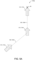
- the local navigation system 120 must navigate a portion of the robot 10 (e.g., the center point of the robot) to a space in the environment 8 that is represented by the interior of the goal region 220, the size of the goal region 220 establishes how near the waypoint 510 the robot 10 will get.
- Each goal region 220 may include a yaw bound or yaw constraint that the robot must conform to before successfully satisfy or complete the respective goal region 220 and move on to the next segment 210. That is, the yaw bound may force the robot 10 to enter a specific yaw configuration prior to leaving the goal region 220 before satisfying the goal region 220 and/or segment 210 while additionally or alternatively, the yaw bound forces the robot 10 to enter the specific yaw configuration before entering the goal region 220. For example, when a goal region 220 is located at the bottom of a staircase (e.g., the goal region 220b of FIG.
- a yaw bound associated with the goal region 220 ensures that the robot 10 is properly aligned with the staircase prior to entering the goal region 220 and/or prior to leaving the goal region 220 and climbing the stairs.
- one or more of the goal regions 220 are configured to cause the robot 10 to align with an obstacle prior to the robot 10 traversing the obstacle.
- the high-level navigation system 110 generates at least one constraint region 230 encompassing at least one goal region 220.
- the constraint region may encompass a plurality of goal regions 220 (e.g., two goal regions 220).
- the at least one constraint region 230 establishes the boundaries for the robot 10 to remain within while traversing toward the target destination or mission destination 46.
- the constraint region 230l encompasses the goal regions 220k, 200l while the constraint region 230m encompasses the goal regions 220l, 220m.
- the constraint regions 230l, 230m bound the areas the robot 10 may enter while the local navigation system 120 navigates the robot around obstacles to the mission destination 46.
- the local navigation system 120 may navigate the robot 10 to the target destination or mission destination 46 by traversing the robot 10 through each goal region 220 (e.g., a center point of the robot 10) while maintaining the robot 10 within the constraint regions 230.
- the constraint region 230 may be any shape. Multiple goal regions 220 may overlap.
- each segment 210 includes only a single constrained region 230 and a single goal region 220.
- one or more of the goal regions 220 provide localization information to the robot 10.
- the underlying waypoint 510 encompassed by the goal region 220 from the previously generated map 50 allows the navigation system 100 to localize the robot 10 within the map 50.
- the high-level navigation system 110 sizes one or more constraint regions 230 to ensure that the robot 10 stays localized with the previously generated map 50. That is, when the robot 10 strays too far away from waypoints 510 and edges 520 from the previously generated map, the navigation system 100 may lose track of the location of the robot within the environment 8.
- the high-level navigation system 110 sizes the constraint region 230, based on, for example, the capabilities of the vision system 14 and the fidelity of the map 50, to keep the robot 10 localized within the map 50.
- the constraint regions 230 may include additional contextual information for the local navigation system 120, such as route cost information.
- an exemplary environment 600 includes a narrow corridor 610 that proceeds a staircase 620.
- the narrow corridor 610 prohibits the robot 10 from turning around at the top of the staircase 620. In this situation, the robot 10 must turn prior to entering the corridor 610 and traverse the corridor 610 backwards.
- the robot 10 executes a turning maneuver to re-orient itself backwards before entering the narrow corridor 61 so that the robot 10 may beneficially traverse down the staircase 620 backwards.
- the constraint region may enforce an orientation constraint on the robot 10, thus commanding the robot 10 to turn around prior (e.g., at or near location 630) to entering the corridor 610.
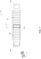
- another exemplary environment 700 includes a staircase 710.
- an initial goal region 220n ensures that the robot 10 is aligned with the staircase 710 prior to traversing the stairs.
- a second goal region 220o along the stairs allows the local navigation system 120 to notify the high-level navigation system 110 when the robot is passing positions of good localization in the environment 700. That is, in this example, the goal region 220o along the staircase 710 represents an area that allows the robot 10 to localize its location to the previously generated map 50.
- a final goal region 220p ensures that the robot 10 is properly off the stairs prior to allowing the robot 10 to turn to proceed to the next segment 210 (not shown).
- the constraint regions 230 provide the robot 10 with position bounds and costs to keep the robot 10 centered on the stairs and to keep the yaw of the robot 10 aligned with the direction of the stairs.
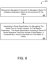
- FIG. 8 is a flowchart of an exemplary arrangement of operations for a method 800 of generating a route specification for navigating a robot 10.
- the method 800 includes receiving, at data processing hardware 36, a navigation command 44 to navigate a robot 10 to a mission destination 46 within an environment 8 of the robot 10.
- the method 800 includes generating, by the data processing hardware 36, a route specification 200 for navigating the robot 10 from a current location 43 in the environment 8 to the mission destination 46 in the environment 8.
- the route specification 200 includes a series of route segments 210.
- Each route segment 210 in the series of route segments includes a goal region 220 for the corresponding route segment 210, a constraint region 230 encompassing the goal region 220, and an initial path 310 for the robot 10 to follow while traversing the corresponding route segment 210.
- the constraint region 230 encompassing the goal region 220 for each corresponding route segment 210 establishes boundaries for the robot 10 to remain within while traversing toward the goal region 220.
- FIG. 9 is schematic view of an example computing device 900 that may be used to implement the systems and methods described in this document.
- the computing device 900 is intended to represent various forms of digital computers, such as laptops, desktops, workstations, personal digital assistants, servers, blade servers, mainframes, and other appropriate computers.
- the components shown here, their connections and relationships, and their functions, are meant to be exemplary only, and are not meant to limit implementations of the inventions described and/or claimed in this document.
- the computing device 900 includes a processor 910, memory 920, a storage device 930, a high-speed interface/controller 940 connecting to the memory 920 and high-speed expansion ports 950, and a low speed interface/controller 960 connecting to a low speed bus 970 and a storage device 930.
- a processor 910 processor 910
- memory 920 memory 920
- storage device 930 storage device 930
- high-speed interface/controller 940 connecting to the memory 920 and high-speed expansion ports 950
- a low speed interface/controller 960 connecting to a low speed bus 970 and a storage device 930.
- Each of the components 910, 920, 930, 940, 950, and 960 are interconnected using various busses, and may be mounted on a common motherboard or in other manners as appropriate.
- the processor 910 can process instructions for execution within the computing device 900, including instructions stored in the memory 920 or on the storage device 930 to display graphical information for a graphical user interface (GUI) on an external input/output device, such as display 980 coupled to high speed interface 940.
- GUI graphical user interface
- multiple processors and/or multiple buses may be used, as appropriate, along with multiple memories and types of memory.
- multiple computing devices 900 may be connected, with each device providing portions of the necessary operations (e.g., as a server bank, a group of blade servers, or a multi-processor system).
- the memory 920 stores information non-transitorily within the computing device 900.
- the memory 920 may be a computer-readable medium, a volatile memory unit(s), or non-volatile memory unit(s).
- the non-transitory memory 920 may be physical devices used to store programs (e.g., sequences of instructions) or data (e.g., program state information) on a temporary or permanent basis for use by the computing device 900.
- non-volatile memory examples include, but are not limited to, flash memory and read-only memory (ROM) / programmable read-only memory (PROM) / erasable programmable read-only memory (EPROM) / electronically erasable programmable read-only memory (EEPROM) (e.g., typically used for firmware, such as boot programs).
- volatile memory examples include, but are not limited to, random access memory (RAM), dynamic random access memory (DRAM), static random access memory (SRAM), phase change memory (PCM) as well as disks or tapes.
- the storage device 930 is capable of providing mass storage for the computing device 900.
- the storage device 930 is a computer-readable medium.
- the storage device 930 may be a floppy disk device, a hard disk device, an optical disk device, or a tape device, a flash memory or other similar solid state memory device, or an array of devices, including devices in a storage area network or other configurations.
- a computer program product is tangibly embodied in an information carrier.
- the computer program product contains instructions that, when executed, perform one or more methods, such as those described above.
- the information carrier is a computer- or machine-readable medium, such as the memory 920, the storage device 930, or memory on processor 910.
- the high speed controller 940 manages bandwidth-intensive operations for the computing device 900, while the low speed controller 960 manages lower bandwidth-intensive operations. Such allocation of duties is exemplary only.
- the high-speed controller 940 is coupled to the memory 920, the display 980 (e.g., through a graphics processor or accelerator), and to the high-speed expansion ports 950, which may accept various expansion cards (not shown).
- the low-speed controller 960 is coupled to the storage device 930 and a low-speed expansion port 990.
- the low-speed expansion port 990 which may include various communication ports (e.g., USB, Bluetooth, Ethernet, wireless Ethernet), may be coupled to one or more input/output devices, such as a keyboard, a pointing device, a scanner, or a networking device such as a switch or router, e.g., through a network adapter.
- input/output devices such as a keyboard, a pointing device, a scanner, or a networking device such as a switch or router, e.g., through a network adapter.
- the computing device 900 may be implemented in a number of different forms, as shown in the figure. For example, it may be implemented as a standard server 900a or multiple times in a group of such servers 900a, as a laptop computer 900b, or as part of a rack server system 900c.
- implementations of the systems and techniques described herein can be realized in digital electronic and/or optical circuitry, integrated circuitry, specially designed ASICs (application specific integrated circuits), computer hardware, firmware, software, and/or combinations thereof.
- ASICs application specific integrated circuits
- These various implementations can include implementation in one or more computer programs that are executable and/or interpretable on a programmable system including at least one programmable processor, which may be special or general purpose, coupled to receive data and instructions from, and to transmit data and instructions to, a storage system, at least one input device, and at least one output device.
- the processes and logic flows described in this specification can be performed by one or more programmable processors, also referred to as data processing hardware, executing one or more computer programs to perform functions by operating on input data and generating output.
- the processes and logic flows can also be performed by special purpose logic circuitry, e.g., an FPGA (field programmable gate array) or an ASIC (application specific integrated circuit).
- processors suitable for the execution of a computer program include, by way of example, both general and special purpose microprocessors, and any one or more processors of any kind of digital computer.
- a processor will receive instructions and data from a read only memory or a random access memory or both.
- the essential elements of a computer are a processor for performing instructions and one or more memory devices for storing instructions and data.
- a computer will also include, or be operatively coupled to receive data from or transfer data to, or both, one or more mass storage devices for storing data, e.g., magnetic, magneto optical disks, or optical disks.
- mass storage devices for storing data
- a computer need not have such devices.
- Computer readable media suitable for storing computer program instructions and data include all forms of non-volatile memory, media and memory devices, including by way of example semiconductor memory devices, e.g., EPROM, EEPROM, and flash memory devices; magnetic disks, e.g., internal hard disks or removable disks; magneto optical disks; and CD ROM and DVD-ROM disks.
- the processor and the memory can be supplemented by, or incorporated in, special purpose logic circuitry.
- one or more aspects of the disclosure can be implemented on a computer having a display device, e.g., a CRT (cathode ray tube), LCD (liquid crystal display) monitor, or touch screen for displaying information to the user and optionally a keyboard and a pointing device, e.g., a mouse or a trackball, by which the user can provide input to the computer.
- a display device e.g., a CRT (cathode ray tube), LCD (liquid crystal display) monitor, or touch screen for displaying information to the user and optionally a keyboard and a pointing device, e.g., a mouse or a trackball, by which the user can provide input to the computer.
- Other kinds of devices can be used to provide interaction with a user as well; for example, feedback provided to the user can be any form of sensory feedback, e.g., visual feedback, auditory feedback, or tactile feedback; and input from the user can be received in any form, including acoustic, speech, or tactile input
Landscapes
- Engineering & Computer Science (AREA)
- Radar, Positioning & Navigation (AREA)
- Remote Sensing (AREA)
- Physics & Mathematics (AREA)
- General Physics & Mathematics (AREA)
- Automation & Control Theory (AREA)
- Aviation & Aerospace Engineering (AREA)
- Control Of Position, Course, Altitude, Or Attitude Of Moving Bodies (AREA)
- Robotics (AREA)
- Mechanical Engineering (AREA)
Claims (14)
- Verfahren (800), umfassend:Empfangen, in einer Datenverarbeitungshardware (36), eines Navigationsbefehls (44), um einen Roboter (10) zu einem Missionsziel (46) innerhalb einer Umgebung (8) des Roboters (10) zu navigieren;Erzeugen, durch die Datenverarbeitungshardware (36), einer Routenspezifikation (200) zum Navigieren des Roboters (100) von einem aktuellen Standort (43) in der Umgebung (8) zu dem Missionsziel (46) in der Umgebung (8), wobei die Routenspezifikation (200) eine Reihe von Routensegmenten (210) umfasst, wobei jedes Routensegment (210) in der Reihe von Routensegmenten (210) umfasst:ein Etappenzielgebiet (220) für das entsprechende Routensegment (210);ein Einschränkungsgebiet (230), welches das Etappenzielgebiet (220) einschließt, wobei das Einschränkungsgebiet (230) Grenzen für den Roboter (10) festlegt, innerhalb derer er bleiben muss, während er in Richtung auf das Etappenzielgebiet (220) läuft, und alle Hindernisse (250) innerhalb des Einschränkungsgebiets (230) vermeidet; undeinen anfänglichen Weg (310) für den Roboter (10), dem er folgen muss, während er das entsprechende Routensegment (210) durchläuft; gekennzeichnet durch:
Anpassen, durch die Datenverarbeitungshardware (36), eines Maßes eines Spielraums (270) für einen Abstand zwischen dem Roboter (10) und den Hindernissen (250) innerhalb des Einschränkungsgebiets (230) basierend auf einer Größe des Einschränkungsgebiets (230). - Verfahren (800) nach Anspruch 1, wobei das Einschränkungsgebiet (230) von jedem Routensegment (210) in der Reihe von Routensegmenten (210) sich mit mindestens einem anderen Einschränkungsgebiet (230) eines anderen Routensegments (210) in der Reihe von Routensegmenten (210) überschneidet.
- Verfahren (800) nach einem der Ansprüche 1 oder 2, wobei das Einschränkungsgebiet (230), welches das Etappenzielgebiet (220) für das entsprechende Routensegment (210) einschließt, auch das Etappenzielgebiet (220) einschließt, das mit einem vorhergehenden Routensegment (210) in der Reihe von Routensegmenten (210) assoziiert ist, das sich mit dem entsprechenden Routensegment (210) überschneidet.
- Verfahren (800) nach einem der Ansprüche 1 bis 3, wobei jedes Etappenzielgebiet (220) eine konvexe Form umfasst.
- Verfahren (800) nach einem der Ansprüche 1 bis 4, wobei jedes Etappenzielgebiet (220) einen Bereich repräsentiert, in den ein Mittelpunkt (202) des Roboters(10) eintritt, während er das Routensegment (210) durchläuft.
- Verfahren (800) nach einem der Ansprüche 1 bis 5, wobei jedes Routensegment (210) ferner mindestens eines von einem Etappenzielaufwand, Geschwindigkeitsgrenzen, einem Positionsaufwand, Positionseinschränkungen, einem Geschwindigkeitsaufwand, Kurseinschränkungen oder Mobilitätsparametern umfasst.
- Verfahren (800) nach Anspruch 6, wobei die Mobilitätsparameter eine Kategorisierung einer Oberfläche innerhalb des entsprechenden Routensegments (210) umfassen; und
wobei die Kategorisierung optional Treppen oder einen ebenen Boden umfasst. - Verfahren (800) nach Anspruch 6, wobei die Geschwindigkeitsgrenzen eine minimale Geschwindigkeit für den Roboter (10), während er das entsprechende Routensegment (210) durchläuft, und eine maximale Geschwindigkeit für den Roboter (10), während er das entsprechende Routensegment (210) durchläuft, umfassen; und
wobei die Geschwindigkeitsgrenzen optional Winkelgeschwindigkeitsgrenzen, seitliche Geschwindigkeitsgrenzen und longitudinale Geschwindigkeitsgrenzen umfassen. - Verfahren (800) nach einem der Ansprüche 1 bis 8, wobei der Roboter (10) jedes Routensegment (210) in der Reihe von Routensegmenten (210) nacheinander durchläuft, indem er jedes entsprechende Etappenzielgebiet (220) durchquert, während er zu dem Missionsziel(46) in der Umgebung (8) navigiert.
- Verfahren (800) nach einem der Ansprüche 1 bis 9, wobei die Routenspezifikation (200) mindestens eine globale Einschränkung (213) umfasst, die konfiguriert ist, um den Roboter (10) einzuschränken, während er jedes Routensegment(210) durchläuft; und
wobei die Datenverarbeitungshardware (36) optional in dem Roboter (10) untergebracht ist. - Verfahren (800) nach einem der Ansprüche 1 bis 10, wobei das Empfangen des Navigationsbefehls (44) ein Empfangen des Navigationsbefehls (44) von einer Benutzervorrichtung (40) umfasst, die in einer Kommunikation mit der Datenverarbeitungshardware (36) steht; und
wobei das Etappenzielgebiet (220) für das letzte Routensegment (210) in der Reihe von Routensegmenten (210) das Missionsziel (46) einschließt. - Verfahren (800) nach einem der Ansprüche 1 bis 11, das ferner umfasst:
Implementieren, durch die Datenverarbeitungshardware (36), eines ersten Navigationssystems (110), das konfiguriert ist zum:Empfangen des Navigationsbefehls(44);Erzeugen der Routenspezifikation(200); undErzeugen des Einschränkungsgebiets (230) für jedes Routensegment (210); undImplementieren, durch die Datenverarbeitungshardware (36), eines zweiten Navigationssystems (120), das konfiguriert ist zum:Empfangen des Einschränkungsgebiets (230) und des anfänglichen Wegs (310) von dem ersten Navigationssystem (110); undErzeugen eines Stufenplans (122) für den Roboter (10), um entlang des anfänglichen Wegs (310) zu navigieren. - Verfahren (800) nach einem der Ansprüche 1 bis 12, das ferner ein Ermitteln, durch die Datenverarbeitungshardware (36) einer Größe des Einschränkungsgebiets (23), basierend auf den Fähigkeiten von mindestens einem Sensor (30) und/oder der Genauigkeit einer Karte (50), umfasst.
- System, umfassend:ein Datenverarbeitungshardware (36); undeine Speicherhardware (38), die in einer Kommunikation mit der Datenverarbeitungshardware (36) steht, wobei in der Speicherhardware (38) Anweisungen gespeichert sind, die, wenn sie in der Datenverarbeitungshardware (36) ausgeführt werden, die Datenverarbeitungshardware (36) veranlassen, das Verfahren (800) nach einem der Ansprüche 1 bis 13 durchzuführen.
Applications Claiming Priority (3)
| Application Number | Priority Date | Filing Date | Title |
|---|---|---|---|
| US202063012515P | 2020-04-20 | 2020-04-20 | |
| US16/884,709 US11927961B2 (en) | 2020-04-20 | 2020-05-27 | Constrained robot autonomy language |
| PCT/US2021/022879 WO2021216233A1 (en) | 2020-04-20 | 2021-03-18 | Constrained robot autonomy language |
Publications (2)
| Publication Number | Publication Date |
|---|---|
| EP4139764A1 EP4139764A1 (de) | 2023-03-01 |
| EP4139764B1 true EP4139764B1 (de) | 2025-07-02 |
Family
ID=78081028
Family Applications (1)
| Application Number | Title | Priority Date | Filing Date |
|---|---|---|---|
| EP21717720.3A Active EP4139764B1 (de) | 2020-04-20 | 2021-03-18 | Eingeschränkte roboterautonomiesprache |
Country Status (4)
| Country | Link |
|---|---|
| US (1) | US11927961B2 (de) |
| EP (1) | EP4139764B1 (de) |
| CN (1) | CN115668088A (de) |
| WO (1) | WO2021216233A1 (de) |
Families Citing this family (4)
| Publication number | Priority date | Publication date | Assignee | Title |
|---|---|---|---|---|
| US11287826B2 (en) | 2018-10-12 | 2022-03-29 | Boston Dynamics, Inc. | Terrain aware step planning system |
| CN114503043B (zh) | 2019-08-06 | 2025-04-01 | 波士顿动力公司 | 受限移动性建图 |
| US11712802B2 (en) | 2020-04-20 | 2023-08-01 | Boston Dynamics, Inc. | Construction constrained motion primitives from robot maps |
| US12468300B2 (en) | 2021-06-04 | 2025-11-11 | Boston Dynamics, Inc. | Detecting negative obstacles |
Family Cites Families (27)
| Publication number | Priority date | Publication date | Assignee | Title |
|---|---|---|---|---|
| US7418312B2 (en) * | 2003-09-19 | 2008-08-26 | Sony Corporation | Robot apparatus and walking control method thereof |
| US20060167622A1 (en) * | 2005-01-24 | 2006-07-27 | Bodin William K | Navigating UAVs in formations |
| US7587260B2 (en) | 2006-07-05 | 2009-09-08 | Battelle Energy Alliance, Llc | Autonomous navigation system and method |
| EP2821875A3 (de) | 2008-09-03 | 2015-05-20 | Murata Machinery, Ltd. | Routenplanungsverfahren, Routenplanungseinheit und autonomes Mobilgerät |
| KR101667030B1 (ko) | 2009-08-10 | 2016-10-17 | 삼성전자 주식회사 | 로봇의 경로 계획 장치 및 그 방법 |
| US9744672B2 (en) | 2011-11-16 | 2017-08-29 | University Of South Florida | Systems and methods for communicating robot intentions to human beings |
| JP5945419B2 (ja) | 2012-01-10 | 2016-07-05 | 本田技研工業株式会社 | 脚式移動ロボットの脚体運動軌道生成装置。 |
| US9233470B1 (en) | 2013-03-15 | 2016-01-12 | Industrial Perception, Inc. | Determining a virtual representation of an environment by projecting texture patterns |
| JP6071839B2 (ja) | 2013-10-22 | 2017-02-01 | 本田技研工業株式会社 | 脚式移動ロボットの制御システム |
| US9583006B2 (en) * | 2014-05-20 | 2017-02-28 | Verizon Patent And Licensing Inc. | Identifying unmanned aerial vehicles for mission performance |
| EP3399381A1 (de) * | 2014-09-05 | 2018-11-07 | SZ DJI Technology Co., Ltd. | Kontextbasierte flugmodusauswahl |
| US9844877B1 (en) | 2015-07-14 | 2017-12-19 | X Development Llc | Generating a parameter for a movement characteristic for a waypoint trained path of a robot |
| WO2017123761A1 (en) | 2016-01-15 | 2017-07-20 | Irobot Corporation | Autonomous monitoring robot systems |
| US10035266B1 (en) | 2016-01-18 | 2018-07-31 | X Development Llc | Generating robot trajectories using a real time trajectory generator and a path optimizer |
| US10163357B2 (en) * | 2016-08-24 | 2018-12-25 | Qualcomm Incorporated | Navigation assistance data and route planning for drones |
| US10012988B2 (en) | 2016-11-29 | 2018-07-03 | Mitsubishi Electric Research Laboratories, Inc. | Methods and systems for path planning using a network of safe-sets |
| US9844879B1 (en) | 2017-05-17 | 2017-12-19 | Savioke, Inc. | System and method for utilizing non-local information to constrain robot services |
| US10503172B2 (en) * | 2017-10-18 | 2019-12-10 | Luminar Technologies, Inc. | Controlling an autonomous vehicle based on independent driving decisions |
| US10606269B2 (en) | 2017-12-19 | 2020-03-31 | X Development Llc | Semantic obstacle recognition for path planning |
| KR102090590B1 (ko) | 2018-06-08 | 2020-04-23 | 엘지전자 주식회사 | 장애물 회피에 기반하여 경유 지점을 주행하는 로봇 및 주행하는 방법 |
| EP3823795A4 (de) | 2018-07-16 | 2022-04-06 | Brain Corporation | Systeme und verfahren zur optimierung der routenplanung für enge wendungen für robotergeräte |
| US11364903B2 (en) | 2018-09-28 | 2022-06-21 | Logistics and Supply Chain MultiTech R&D Centre Limited | Automated guide vehicle with a collision avoidance apparatus |
| US11747825B2 (en) | 2018-10-12 | 2023-09-05 | Boston Dynamics, Inc. | Autonomous map traversal with waypoint matching |
| US11314254B2 (en) | 2019-03-26 | 2022-04-26 | Intel Corporation | Methods and apparatus for dynamically routing robots based on exploratory on-board mapping |
| US11268816B2 (en) | 2019-08-06 | 2022-03-08 | Boston Dynamics, Inc. | Intermediate waypoint generator |
| US11518410B2 (en) * | 2020-02-17 | 2022-12-06 | Wipro Limited | Method and system for generating velocity profiles for autonomous vehicles |
| US11712802B2 (en) | 2020-04-20 | 2023-08-01 | Boston Dynamics, Inc. | Construction constrained motion primitives from robot maps |
-
2020
- 2020-05-27 US US16/884,709 patent/US11927961B2/en active Active
-
2021
- 2021-03-18 WO PCT/US2021/022879 patent/WO2021216233A1/en not_active Ceased
- 2021-03-18 CN CN202180037469.0A patent/CN115668088A/zh active Pending
- 2021-03-18 EP EP21717720.3A patent/EP4139764B1/de active Active
Also Published As
| Publication number | Publication date |
|---|---|
| CN115668088A (zh) | 2023-01-31 |
| WO2021216233A1 (en) | 2021-10-28 |
| US20210325893A1 (en) | 2021-10-21 |
| US11927961B2 (en) | 2024-03-12 |
| EP4139764A1 (de) | 2023-03-01 |
Similar Documents
| Publication | Publication Date | Title |
|---|---|---|
| US12508706B2 (en) | Construction constrained motion primitives from robot maps | |
| EP3864483B1 (de) | Geländebewusstes stufenplanungssystem | |
| EP4139764B1 (de) | Eingeschränkte roboterautonomiesprache | |
| KR102844845B1 (ko) | 중간 웨이포인트 생성기 | |
| EP4348377B1 (de) | Alternative routenfindung für wegpunktbasierte navigationskarten | |
| US20220260998A1 (en) | Navigating a Mobile Robot | |
| Ye | Navigating a mobile robot by a traversability field histogram | |
| Monteiro et al. | Attractor dynamics approach to formation control: theory and application | |
| US11865724B2 (en) | Movement control method, mobile machine and non-transitory computer readable storage medium | |
| Claes et al. | Towards human-safe navigation with pro-active collision avoidance in a shared workspace | |
| Calisi et al. | A semi-autonomous tracked robot system for rescue missions | |
| Bhargava et al. | A hybrid optimization algorithm combining A* and the dynamic window approach for automated guided vehicle control in static and dynamic environments | |
| US20260062075A1 (en) | Performance of docking maneuvers by legged robots using dock associations | |
| Thorpe et al. | Chairs |
Legal Events
| Date | Code | Title | Description |
|---|---|---|---|
| STAA | Information on the status of an ep patent application or granted ep patent |
Free format text: STATUS: UNKNOWN |
|
| STAA | Information on the status of an ep patent application or granted ep patent |
Free format text: STATUS: THE INTERNATIONAL PUBLICATION HAS BEEN MADE |
|
| PUAI | Public reference made under article 153(3) epc to a published international application that has entered the european phase |
Free format text: ORIGINAL CODE: 0009012 |
|
| STAA | Information on the status of an ep patent application or granted ep patent |
Free format text: STATUS: REQUEST FOR EXAMINATION WAS MADE |
|
| 17P | Request for examination filed |
Effective date: 20221018 |
|
| AK | Designated contracting states |
Kind code of ref document: A1 Designated state(s): AL AT BE BG CH CY CZ DE DK EE ES FI FR GB GR HR HU IE IS IT LI LT LU LV MC MK MT NL NO PL PT RO RS SE SI SK SM TR |
|
| P01 | Opt-out of the competence of the unified patent court (upc) registered |
Effective date: 20230510 |
|
| DAV | Request for validation of the european patent (deleted) | ||
| DAX | Request for extension of the european patent (deleted) | ||
| STAA | Information on the status of an ep patent application or granted ep patent |
Free format text: STATUS: EXAMINATION IS IN PROGRESS |
|
| 17Q | First examination report despatched |
Effective date: 20231121 |
|
| REG | Reference to a national code |
Ref legal event code: R079 Free format text: PREVIOUS MAIN CLASS: G05D0001020000 Ipc: G05D0001000000 Ref country code: DE Ref document number: 602021033309 Country of ref document: DE |
|
| GRAP | Despatch of communication of intention to grant a patent |
Free format text: ORIGINAL CODE: EPIDOSNIGR1 |
|
| STAA | Information on the status of an ep patent application or granted ep patent |
Free format text: STATUS: GRANT OF PATENT IS INTENDED |
|
| RIC1 | Information provided on ipc code assigned before grant |
Ipc: B25J 9/16 20060101ALN20250115BHEP Ipc: G01C 21/20 20060101ALI20250115BHEP Ipc: G05D 1/00 20060101AFI20250115BHEP |
|
| INTG | Intention to grant announced |
Effective date: 20250205 |
|
| GRAS | Grant fee paid |
Free format text: ORIGINAL CODE: EPIDOSNIGR3 |
|
| GRAA | (expected) grant |
Free format text: ORIGINAL CODE: 0009210 |
|
| STAA | Information on the status of an ep patent application or granted ep patent |
Free format text: STATUS: THE PATENT HAS BEEN GRANTED |
|
| AK | Designated contracting states |
Kind code of ref document: B1 Designated state(s): AL AT BE BG CH CY CZ DE DK EE ES FI FR GB GR HR HU IE IS IT LI LT LU LV MC MK MT NL NO PL PT RO RS SE SI SK SM TR |
|
| REG | Reference to a national code |
Ref country code: GB Ref legal event code: FG4D |
|
| REG | Reference to a national code |
Ref country code: CH Ref legal event code: EP |
|
| REG | Reference to a national code |
Ref country code: DE Ref legal event code: R096 Ref document number: 602021033309 Country of ref document: DE |
|
| REG | Reference to a national code |
Ref country code: IE Ref legal event code: FG4D |
|
| REG | Reference to a national code |
Ref country code: NL Ref legal event code: MP Effective date: 20250702 |
|
| PG25 | Lapsed in a contracting state [announced via postgrant information from national office to epo] |
Ref country code: PT Free format text: LAPSE BECAUSE OF FAILURE TO SUBMIT A TRANSLATION OF THE DESCRIPTION OR TO PAY THE FEE WITHIN THE PRESCRIBED TIME-LIMIT Effective date: 20251103 |
|
| PG25 | Lapsed in a contracting state [announced via postgrant information from national office to epo] |
Ref country code: NL Free format text: LAPSE BECAUSE OF FAILURE TO SUBMIT A TRANSLATION OF THE DESCRIPTION OR TO PAY THE FEE WITHIN THE PRESCRIBED TIME-LIMIT Effective date: 20250702 |
|
| REG | Reference to a national code |
Ref country code: AT Ref legal event code: MK05 Ref document number: 1809933 Country of ref document: AT Kind code of ref document: T Effective date: 20250702 |
|
| PG25 | Lapsed in a contracting state [announced via postgrant information from national office to epo] |
Ref country code: IS Free format text: LAPSE BECAUSE OF FAILURE TO SUBMIT A TRANSLATION OF THE DESCRIPTION OR TO PAY THE FEE WITHIN THE PRESCRIBED TIME-LIMIT Effective date: 20251102 |
|
| PG25 | Lapsed in a contracting state [announced via postgrant information from national office to epo] |
Ref country code: NO Free format text: LAPSE BECAUSE OF FAILURE TO SUBMIT A TRANSLATION OF THE DESCRIPTION OR TO PAY THE FEE WITHIN THE PRESCRIBED TIME-LIMIT Effective date: 20251002 |
|
| REG | Reference to a national code |
Ref country code: LT Ref legal event code: MG9D |
|
| PG25 | Lapsed in a contracting state [announced via postgrant information from national office to epo] |
Ref country code: AT Free format text: LAPSE BECAUSE OF FAILURE TO SUBMIT A TRANSLATION OF THE DESCRIPTION OR TO PAY THE FEE WITHIN THE PRESCRIBED TIME-LIMIT Effective date: 20250702 |
|
| PG25 | Lapsed in a contracting state [announced via postgrant information from national office to epo] |
Ref country code: FI Free format text: LAPSE BECAUSE OF FAILURE TO SUBMIT A TRANSLATION OF THE DESCRIPTION OR TO PAY THE FEE WITHIN THE PRESCRIBED TIME-LIMIT Effective date: 20250702 |
|
| PG25 | Lapsed in a contracting state [announced via postgrant information from national office to epo] |
Ref country code: HR Free format text: LAPSE BECAUSE OF FAILURE TO SUBMIT A TRANSLATION OF THE DESCRIPTION OR TO PAY THE FEE WITHIN THE PRESCRIBED TIME-LIMIT Effective date: 20250702 |
|
| PG25 | Lapsed in a contracting state [announced via postgrant information from national office to epo] |
Ref country code: GR Free format text: LAPSE BECAUSE OF FAILURE TO SUBMIT A TRANSLATION OF THE DESCRIPTION OR TO PAY THE FEE WITHIN THE PRESCRIBED TIME-LIMIT Effective date: 20251003 |
|
| PG25 | Lapsed in a contracting state [announced via postgrant information from national office to epo] |
Ref country code: SE Free format text: LAPSE BECAUSE OF FAILURE TO SUBMIT A TRANSLATION OF THE DESCRIPTION OR TO PAY THE FEE WITHIN THE PRESCRIBED TIME-LIMIT Effective date: 20250702 Ref country code: CZ Free format text: LAPSE BECAUSE OF FAILURE TO SUBMIT A TRANSLATION OF THE DESCRIPTION OR TO PAY THE FEE WITHIN THE PRESCRIBED TIME-LIMIT Effective date: 20250702 |
|
| PG25 | Lapsed in a contracting state [announced via postgrant information from national office to epo] |
Ref country code: LV Free format text: LAPSE BECAUSE OF FAILURE TO SUBMIT A TRANSLATION OF THE DESCRIPTION OR TO PAY THE FEE WITHIN THE PRESCRIBED TIME-LIMIT Effective date: 20250702 |
|
| PG25 | Lapsed in a contracting state [announced via postgrant information from national office to epo] |
Ref country code: PL Free format text: LAPSE BECAUSE OF FAILURE TO SUBMIT A TRANSLATION OF THE DESCRIPTION OR TO PAY THE FEE WITHIN THE PRESCRIBED TIME-LIMIT Effective date: 20250702 Ref country code: BG Free format text: LAPSE BECAUSE OF FAILURE TO SUBMIT A TRANSLATION OF THE DESCRIPTION OR TO PAY THE FEE WITHIN THE PRESCRIBED TIME-LIMIT Effective date: 20250702 |
|
| PG25 | Lapsed in a contracting state [announced via postgrant information from national office to epo] |
Ref country code: RS Free format text: LAPSE BECAUSE OF FAILURE TO SUBMIT A TRANSLATION OF THE DESCRIPTION OR TO PAY THE FEE WITHIN THE PRESCRIBED TIME-LIMIT Effective date: 20251002 |
|
| PG25 | Lapsed in a contracting state [announced via postgrant information from national office to epo] |
Ref country code: ES Free format text: LAPSE BECAUSE OF FAILURE TO SUBMIT A TRANSLATION OF THE DESCRIPTION OR TO PAY THE FEE WITHIN THE PRESCRIBED TIME-LIMIT Effective date: 20250702 |
|
| REG | Reference to a national code |
Ref country code: CH Ref legal event code: U11 Free format text: ST27 STATUS EVENT CODE: U-0-0-U10-U11 (AS PROVIDED BY THE NATIONAL OFFICE) Effective date: 20260401 |
|
| PG25 | Lapsed in a contracting state [announced via postgrant information from national office to epo] |
Ref country code: SM Free format text: LAPSE BECAUSE OF FAILURE TO SUBMIT A TRANSLATION OF THE DESCRIPTION OR TO PAY THE FEE WITHIN THE PRESCRIBED TIME-LIMIT Effective date: 20250702 |
|
| PGFP | Annual fee paid to national office [announced via postgrant information from national office to epo] |
Ref country code: GB Payment date: 20260327 Year of fee payment: 6 |
|
| PG25 | Lapsed in a contracting state [announced via postgrant information from national office to epo] |
Ref country code: DK Free format text: LAPSE BECAUSE OF FAILURE TO SUBMIT A TRANSLATION OF THE DESCRIPTION OR TO PAY THE FEE WITHIN THE PRESCRIBED TIME-LIMIT Effective date: 20250702 |
|
| PGFP | Annual fee paid to national office [announced via postgrant information from national office to epo] |
Ref country code: DE Payment date: 20260327 Year of fee payment: 6 |
|
| PG25 | Lapsed in a contracting state [announced via postgrant information from national office to epo] |
Ref country code: IT Free format text: LAPSE BECAUSE OF FAILURE TO SUBMIT A TRANSLATION OF THE DESCRIPTION OR TO PAY THE FEE WITHIN THE PRESCRIBED TIME-LIMIT Effective date: 20250702 |
|
| PGFP | Annual fee paid to national office [announced via postgrant information from national office to epo] |
Ref country code: FR Payment date: 20260325 Year of fee payment: 6 |
|
| PG25 | Lapsed in a contracting state [announced via postgrant information from national office to epo] |
Ref country code: SK Free format text: LAPSE BECAUSE OF FAILURE TO SUBMIT A TRANSLATION OF THE DESCRIPTION OR TO PAY THE FEE WITHIN THE PRESCRIBED TIME-LIMIT Effective date: 20250702 Ref country code: EE Free format text: LAPSE BECAUSE OF FAILURE TO SUBMIT A TRANSLATION OF THE DESCRIPTION OR TO PAY THE FEE WITHIN THE PRESCRIBED TIME-LIMIT Effective date: 20250702 |