EP4139670B1 - Verfahren zur bestimmung einer sauerstoffkonzentration in einem abgas - Google Patents
Verfahren zur bestimmung einer sauerstoffkonzentration in einem abgas Download PDFInfo
- Publication number
- EP4139670B1 EP4139670B1 EP21719549.4A EP21719549A EP4139670B1 EP 4139670 B1 EP4139670 B1 EP 4139670B1 EP 21719549 A EP21719549 A EP 21719549A EP 4139670 B1 EP4139670 B1 EP 4139670B1
- Authority
- EP
- European Patent Office
- Prior art keywords
- electrode
- pump cell
- signal
- variable
- sensor element
- Prior art date
- Legal status (The legal status is an assumption and is not a legal conclusion. Google has not performed a legal analysis and makes no representation as to the accuracy of the status listed.)
- Active
Links
Images


Classifications
-
- G—PHYSICS
- G01—MEASURING; TESTING
- G01N—INVESTIGATING OR ANALYSING MATERIALS BY DETERMINING THEIR CHEMICAL OR PHYSICAL PROPERTIES
- G01N27/00—Investigating or analysing materials by the use of electric, electrochemical, or magnetic means
- G01N27/26—Investigating or analysing materials by the use of electric, electrochemical, or magnetic means by investigating electrochemical variables; by using electrolysis or electrophoresis
- G01N27/416—Systems
- G01N27/417—Systems using cells, i.e. more than one cell and probes with solid electrolytes
- G01N27/4175—Calibrating or checking the analyser
Definitions
- a sensor element for measuring an oxygen concentration in an exhaust gas has a solid electrolyte, a first electrode, a second electrode, a third electrode and a fourth electrode.
- the first electrode and the second electrode are connected to the solid electrolyte in such a way that the first electrode, the second electrode and the solid electrolyte form a pump cell.
- the third electrode and the fourth electrode are connected to the solid electrolyte in such a way that the third electrode, the fourth electrode and the solid electrolyte form a Nernst cell.
- the sensor also has a control loop for controlling a Nernst voltage of the Nernst cell.
- the control loop has a control device which has a manipulated variable, a first controlled variable and a second controlled variable, wherein the manipulated variable is an output variable supplied to the pump cell, the first controlled variable is the Nernst voltage of the Nernst cell and the second controlled variable is a voltage at the first electrode.
- the present invention goes beyond these known approaches and relates to a method for determining an oxygen concentration in an exhaust gas using a sensor element.
- the sensor element used in the method according to the invention has the following structural features: in its interior a cavity that is connected to the exhaust gas via an access opening, in its interior also a reference space that is separated from the cavity, an electrochemical pump cell that has a first electrode that is exposed to the exhaust gas on the outside of the sensor element and that has a second electrode that is arranged in the cavity and that has a first solid electrolyte via which the first electrode is conductively connected to the second electrode oxygen ions, an electrochemical Nernst cell that has a third electrode that is arranged in the cavity and that has a fourth electrode that is arranged in the reference space and that has a second solid electrolyte via which the third electrode is conductively connected to the fourth electrode oxygen ions.
- It can, for example, be a planar, ceramic sensor element, as is known from the state of the art, for example from the above-mentioned DE 10 2015 201 396 A1 , is already known in principle.
- the solid electrolytes can, for example, be areas of the ceramic sensor element that consist of yttrium-stabilized zirconium oxide (YSZ) and therefore have conductivity for oxygen ions in elevated temperature ranges.
- YSZ yttrium-stabilized zirconium oxide
- the second solid electrolyte can be formed separately from the first solid electrolyte or in a common layer plane of the sensor element from a contiguous region of the sensor element made of a solid electrolytic material (e.g. YSZ).
- a solid electrolytic material e.g. YSZ
- the electrodes can be, for example, cermet electrodes, which have a ceramic and a noble metal component.
- the noble metal can be platinum.
- the catalytic activity of the electrodes can be suitably selected by adding proportions of other noble metals or other substances, for example, it can be reduced by adding a gold component.
- the third electrode in the cavity is spatially spaced from the second electrode.
- the third electrode in the cavity can be spatially spaced from the second electrode further or significantly further (e.g. at least twice or three times as far) in a lateral direction than corresponds to a height (i.e. perpendicular to the lateral direction) of the cavity.
- centroid of the third electrode in the cavity is spatially spaced from the centroid of the second electrode.
- the centroid of the third electrode in the cavity can be spatially spaced from the centroid of the second electrode significantly further (e.g. at least twice or five times as far) in a lateral direction than corresponds to a height (i.e. perpendicular to the lateral direction) of the cavity.
- the method according to the invention provides that the oxygen concentration in the cavity is regulated to a constant value by detecting a Nernst voltage signal that represents the Nernst voltage that develops at the Nernst cell, detecting or determining at least one further variable, determining a compensated signal from the Nernst voltage signal and from the at least one further variable, determining an error signal as the difference between a target value and the compensated signal, feeding the error signal to a controller as an input variable, applying the output variable of the controller to the pump cell so that a current flow through the pump cell results. It further provides that a signal representing the current flow through the pump cell is output as a measurement variable of the oxygen concentration in the exhaust gas.
- a signal particularly a Nernst voltage signal that represents the Nernst voltage that develops in the Nernst cell, can be an analog signal whose value is identical to the Nernst voltage. It can also be an analog signal that results unambiguously from the Nernst voltage, i.e. is proportional to the Nernst voltage, for example. It can also be a digital representation of the signals mentioned.
- Analogous to this is a signal that represents the flow of current through the pump cell. It can be an analog signal that is identical to the current, but it can also be an analog signal that results unambiguously from the current, for example the voltage drop across a measuring resistor through which the current flows and which is usually proportional to the current. It can also be a signal that is generated, for example, in a signal processing of the controller described, and according to which (for example proportional to) a current flow is caused through the pump cell. It can also be a digital representation of the signals mentioned.
- Analogous to this is a signal that represents the voltage at the pump cell. It can be an analog signal that is identical to the voltage between the first electrode and the second electrode, but it can also be an analog signal that results unambiguously from the voltage, for example the current across a measuring resistor to which the voltage is applied and which is dependent on (for example proportional to) the voltage. It can also be a digital representation of the signals mentioned.
- the setpoint can be a fixed value. On the other hand, it can also be a value that is not completely constant, but changes very little (e.g. less than 1%) within a time constant that characterizes the control (e.g. 1s), for example in response to certain external events such as to compensate for aging effects or temperature drifts of the sensor element or an evaluation unit working with the sensor element, or for example in response to a change in the oxygen partial pressure in the ambient air of the sensor element.
- Different operating modes can also be provided (e.g. normal operating mode, initialization mode, self-calibration mode, etc.), whereby within the respective operating mode an individual but fixed (or only very slowly varying, see above) value is provided as the setpoint.
- the at least one further quantity may be a single quantity which is not the Nernst voltage and is not a quantity representing the Nernst voltage. It may be a pump current signal which causes a current flow through the pump cell or a pump cell signal that represents a voltage at the pump cell.
- the further variable is or includes a pump cell signal that represents a voltage at the pump cell.
- the further variable is, as a single variable, a pump cell signal that represents a voltage at the pump cell.
- the additional quantity is the voltage at the first electrode together with other additional quantities; and/or if it is expressly excluded that the additional quantity is a single additional quantity, the voltage at the first electrode, this has the advantage in both cases that this quantity, which is partly strongly non-linearly dependent on the oxygen concentration in the exhaust gas, is not included in the compensated signal, or not included alone.
- the at least one further variable can be a plurality of variables, each of which is not the Nernst voltage and is also not a variable representing the Nernst voltage.
- the plurality of variables can be two variables, three variables or more than three variables. It can be provided that the plurality contains at least two of the following variables: a pump current signal that represents a current flow through the pump cell; a pump cell signal that represents a voltage at the pump cell.
- the at least one further variable is a plurality of variables
- the feature that a compensated signal is determined from the Nernst voltage signal and from the at least one further variable means that the compensated signal is determined from the Nernst voltage signal and from each individual variable contained in the plurality of variables, i.e. the compensated signal is dependent on the Nernst voltage signal and on each of the variables contained in the plurality of variables.
- the error signal is fed to the controller as the only input variable of the controller. It can be provided in particular that the controller has only one output variable, namely the output variable that is applied to the pump cell (possibly after amplification) so that a current flow through the pump cell.
- the output variable of the controller or the only output variable of the controller can be, for example, a set voltage or a set current. While the use of a set voltage has the advantage that it can be implemented using simple means, the use of a set current in this case has the advantage of a more stable control loop.
- the invention is based on the further finding that, from a control engineering perspective, there are transit times within the sensor element or within the cavity. If oxygen is transported into the cavity via the pump cell (or out of the cavity), this immediately changes the oxygen concentration in the area of the pump cell, i.e. in the area of the second electrode; however, the Nernst voltage does not change immediately, but only when the oxygen concentration in the cavity has also changed in the area of the Nernst cell, i.e. in the area of the third electrode. Depending on the geometry of the cavity and the arrangement of the second and third electrodes relative to one another in the cavity, a certain amount of time passes before changes in the oxygen concentration within the cavity occur at the pump cell (second electrode) and also at the Nernst cell (third electrode).
- run times within a control system reduce the possible control bandwidth, i.e. the dynamics with which stable control can be achieved. In the present case, this applies to the Nernst voltage as a controlled variable, as explained above.
- the present invention is based on using the compensated signal rather than the Nernst voltage as the control variable.
- the compensated signal represents the oxygen concentration in the entire cavity better than the Nernst voltage, as it takes into account at least one other variable in addition to the Nernst voltage and thus compensates for the transit time effects within the cavity - as it were by mathematically anticipating them based on the Nernst voltage signal.
- the pump current and signals representing it contain the information about oxygen that is currently being introduced into the cavity in the area of the pump cell.
- the use of the pump current as at least one additional quantity thus opens up the possibility of representing the changes in the oxygen concentration in the cavity in the compensated signal even before the Nernst voltage changes accordingly. the changes in the oxygen concentration in the cavity. In other words, the future change in the Nernst voltage is anticipated in the compensated signal.
- a pump current signal can also be the quantity U NP1 - U P1 , i.e. I P1 *R P1 , since this pump current signal represents a current flowing through the pump cell.
- the pump cell signal is another quantity that can be used to form a compensated signal that can represent the oxygen concentration in the cavity more precisely and dynamically than the Nernst voltage alone can.
- time-delayed compensated signal as at least one additional variable, feedback can be implemented, which optimizes the dynamics and stability of the compensation with regard to the transport processes inside the sensor element.
- the compensation should be carried out as precisely as possible to the extent that the Nernst voltage reflects the actual oxygen concentration in the cavity. inadequately represented.
- This feedback changes the frequency characteristics of the entire system. For example, it can become narrower or wider band.
- the sensor element can be a NOx sensor that determines not only the oxygen concentration but also the nitrogen oxide concentration in the exhaust gas.
- This NOx sensor has in particular the following structural features: in its interior a further cavity that is connected to the cavity and a further pump cell that has a fifth electrode that is arranged in the further cavity and a sixth electrode that is arranged outside the further cavity and a third solid electrolyte that connects the fifth electrode and the sixth electrode oxygen ions to one another in a conductive manner.
- the cavity can be spatially separated from the other cavity, for example by a channel-shaped and/or porous diffusion resistance element.
- the fifth electrode consists of a more catalytically active material than the second and/or third electrode, so that the fifth electrode is able to catalytically split NOx, but not (or to a lesser extent) the second and/or third electrode.
- the third solid electrolyte can be formed separately from the first solid electrolyte or, for example, in a common layer plane of the sensor element, from a contiguous region of the sensor element made of a solid electrolytic material (e.g. YSZ).
- the third solid electrolyte can be formed separately from the second solid electrolyte or, for example, in a common layer plane of the sensor element, from a contiguous region of the sensor element made of a solid electrolytic material (e.g. YSZ).
- the first, second and third solid electrolytes can also all be formed together from a contiguous region of the sensor element made of a solid electrolytic material (e.g. YSZ).
- This NOx sensor can be operated by applying an electrical voltage to the additional pump cell and outputting a value representing the resulting current flow through the second pump cell as a measurement of the nitrogen oxide concentration in the exhaust gas.
- a NOx sensor that only comprises three electrochemical cells, namely the pump cell, the Nernst cell and the additional pump cell.
- Such a sensor is particularly simple and particularly benefits from the present invention.
- It can also be a sensor element that can measure not only the concentrations of oxygen and NOx but also the concentration of NH3 and/or other types of gas in the exhaust gas.
- the sensor element can also be a two-cell broadband lambda sensor.
- the sensor element can be a heatable sensor element that has an electrical resistance heater that can be contacted from the outside. Heating can be achieved in particular by detecting a temperature signal that represents a temperature of the sensor element and comparing it with another setpoint value and a further controller controlling an electrical supply to the electrical resistance heater in such a way that the sensor element assumes the specified temperature.
- the further setpoint value can, for example, correspond to a temperature of the sensor element in the range of 700°C to 800°C.
- the further setpoint value can be a fixed value or a value that is adjusted slowly (much slower than the time constant of the further control) according to certain events, for example according to the aging of the sensor element.
- the output of the controller can be a voltage (possibly after DA conversion and/or amplification) that is applied to the pump cell, resulting in a current flow through the pump cell.
- the output of the controller can be a current (possibly after DA conversion and/or amplification).
- the provision A controlled voltage source has the advantage of lower complexity.
- the provision of a controlled current source can have the advantage of more stable regulation in this case.
- the compensated signal is determined from the Nernst voltage signal and the at least one further variable, specifically as a function of the Nernst voltage signal and the signal that results from the at least one further variable by high-pass and/or band-pass filtering. In this way, the suitability of the compensated signal to represent the oxygen concentration in the cavity precisely and with high dynamics can be further optimized.
- a single input quantity q for the high-pass and/or band-pass filtering can initially be determined from the plurality of quantities.
- the output quantity z of the high-pass and/or band-pass filtering is then the addressed signal, from which the compensated signal is formed by summation with the Nernst voltage signal.
- the high-pass and/or band-pass filtering is optimized with regard to the sensor element and the way in which it is operated.
- the output of the high-pass and/or band-pass filtering is in particular DC-free. This reflects a situation in which the influence of the other variable (e.g. the pump current) for static values and for extremely slow changes of the other variable (e.g. the pump current) is already correctly taken into account by the controller when the Nernst voltage is used as the controlled variable. With regard to the static In this case or in the case of extremely slow changes, this DC-free compensation avoids a distortion of the controlled variable.
- the other variable e.g. the pump current
- extremely slow changes of the other variable e.g. the pump current
- the high-pass and/or band-pass filtering attenuates spectral components below 0.5 Hz by at least 3 dB.
- the high-pass and/or band-pass filtering attenuates spectral components between 2 Hz and 5 Hz by less than 3 dB.
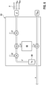
- the evaluation and control unit for carrying out the method according to the invention has the following: inputs to detect a Nernst voltage signal that represents the Nernst voltage that develops at the Nernst cell, a signal processing unit to determine a compensated signal from the Nernst voltage signal and from at least one other variable, a difference former to determine an error signal as a difference between a target value and the compensated signal, a controller to feed the error signal to it as an input variable, outputs to output the output variable of the controller to the pump cell so that a current flows through the pump cell with the aim of regulating the oxygen concentration in the cavity to a constant value, and to output a signal representing the current flow through the pump cell as a measurement variable of the oxygen concentration in the exhaust gas.
- the signal processing unit, the difference generator and the controller can be implemented by physically different components. On the other hand, they can also be functions that are implemented together within a computing unit, either in whole or in part.
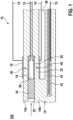
- Figure 1 shows schematically a sensor element 10 of a broadband lambda probe, which is already known in principle from the prior art, in connection with which the method according to the invention can be carried out, for example, and in connection with which the evaluation and control unit according to the invention can be operated, for example.
- the sensor element 10 has a cavity 30 in its interior, which is fluidically connected to an exhaust gas 100 via an access opening 32 and a porous diffusion barrier 34. It also has a reference chamber 38 in its interior, in which a reference gas is located and which is separated from the cavity 30, i.e. is not fluidically connected to the cavity 30 within the sensor element 10.
- the reference gas can be air or oxygen, for example.
- the reference chamber 38 is fluidically connected to the ambient air, for example. However, it can also be a closed chamber within the sensor element 10, in which, for example, a certain oxygen partial pressure is maintained.
- the sensor element 10 further comprises an electrochemical pump cell 36.
- the electrochemical pump cell 36 consists of a first electrode 16 (also: outer pump electrode, APE), which is exposed to the exhaust gas 100 on the outside of the sensor element 10 directly or via a gas-permeable protective layer, and of a second electrode 18 (also: inner pump electrode, IPE), which is arranged in the cavity 30, and of a first solid electrolyte 14a, via which the first electrode 16 is conductively connected to the second electrode 18 oxygen ions.
- APE outer pump electrode
- IPE inner pump electrode
- the sensor element 10 further comprises an electrochemical Nernst cell 40.
- the electrochemical Nernst cell 40 consists of a third electrode 20 (also: Nernst electrode, NE), which is arranged in the cavity 30, and of a fourth electrode 22 (also: reference electrode, RE) and of a second solid electrolyte 14b, via which the third electrode 20 is conductively connected to the fourth electrode 22 oxygen ions.
- first solid electrolyte 14a and the second solid electrolyte 14b are formed together as a single, continuous solid electrolyte body 14.
- first solid electrolyte 14a and the second solid electrolyte 14b can be electrically insulated from one another, for example by a layer of aluminum oxide.
- the sensor element 10 also has an electrical resistance heater 44, which is electrically insulated from the solid electrolyte body 14 by an insulation layer 42.
- the electrical resistance heater 44 can heat the solid electrolyte body 14 to a temperature at which it has a conductivity for oxygen ions, e.g. 780°C.
- the first electrode 16, the second electrode 18, the third electrode 20, the fourth electrode 22 and the electrical resistance heater 44 are electrically connected via supply lines 15 of the sensor element 10 to the outputs and inputs of an evaluation and control device 60 (see Figure 5 ) can be connected.
- the basic functional principle of the Figure 1 The purpose of the sensor element 10 of a broadband lambda probe shown is to regulate a constant oxygen concentration in the cavity with the pump cell 36 as the actuating element and the Nernst cell 40 as the measuring element and to use the pump current as a measured variable for the oxygen concentration c O2 in the exhaust gas 100.
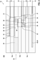
- Figure 2 shows schematically a sensor element 10 of a NOx sensor, which is already known in principle from the prior art, in connection with which the method according to the invention can be carried out, for example.
- the sensor element 10 shown has a cavity 30 in its interior which is fluidically connected to an exhaust gas 100 via an access opening 32 and a porous diffusion barrier 34. It also has a reference chamber 38 in its interior in which a reference gas is located and which is separated from the cavity 30.
- the sensor element 10 further comprises an electrochemical pump cell 36.
- the electrochemical pump cell 36 consists of a first electrode 16 (also: external pump electrode, APE), which is exposed to the exhaust gas 100 on the outside of the sensor element 10 directly or via a gas-permeable protective layer, and of a second electrode 18 (also: internal pump electrode, IPE), which is arranged in the cavity 30, and of a first solid electrolyte 14a, via which the first electrode 16 is conductively connected to the second electrode 18 oxygen ions.
- APE external pump electrode
- IPE internal pump electrode
- the sensor element 10 further comprises an electrochemical Nernst cell 40.
- the electrochemical Nernst cell 40 consists of a third electrode 20 (also: Nernst electrode, NE), which is arranged in the cavity 30, and of a fourth electrode 22 (also: reference electrode, RE) and of a second solid electrolyte 14b, via which the third electrode 20 is conductively connected to the fourth electrode 22 oxygen ions.
- the sensor element 10 further comprises an electrical resistance heater 44.
- the first electrode 16, the second electrode 18, the third electrode 20, the fourth electrode 22 and the electrical resistance heater 44 can be electrically connected to the outputs and inputs of an evaluation and control device 60 via supply lines 15 of the sensor element 10.
- the sensor element 10 of the NOx sensor has a further cavity 31 in its interior, which is fluidically connected to the cavity 30, for example via a further porous diffusion barrier 35.
- the sensor element 10 also has a further electrochemical pump cell 37 (also: NOx cell), which comprises a fifth electrode 24 (also: NOx electrode, NOE) arranged in the further cavity 31, and a sixth electrode 26 (also: NOCE NOx chamber electrode) arranged outside the further cavity 31, and a third solid electrolyte 14c which conductively connects the fifth electrode 24 and the sixth electrode 26 oxygen ions to one another.
- the third solid electrolyte 14c can, as in this example, be formed together with the first solid electrolyte 14a and the second solid electrolyte 14b as a single, coherent solid electrolyte body 14.
- the first solid electrolyte 14a, the second solid electrolyte 14b and the third solid electrolyte 14c can also be electrically insulated from one another in pairs, or only one of the three solid electrolytes 14a, 14b, 14c mentioned could be electrically insulated from the other two.
- the fifth electrode 24 consists of a more catalytically active material than the second and third electrodes 18, 20, so that the fifth electrode 24 is able to catalytically split NOx, but not (or hardly at all) the second and third electrodes 18, 20.
- the second and third electrodes 18, 20 can consist of a cermet, the metallic components of which each contain both platinum and gold, while the fifth electrode 24 contains only platinum and no gold as a metallic component.
- the sensor element 10 of a NOx sensor shown is initially similar to the one shown with reference to Figure 1 explained sensor element of a broadband lambda probe, with the pump cell 36 as the control element and the Nernst cell 40 as the measuring element to regulate a constant oxygen concentration in the cavity 30 and to use the pump current as a measured variable for the oxygen concentration C O2 in the exhaust gas 100.
- This is done here ( Figure 2 ; sensor element of a NOx sensor), however, with the proviso that the catalytic activity of the second and third electrodes 18, 20 or the electrical voltage applied to the pump cell 36 is reduced to such an extent that an electrochemical splitting of NOx molecules initially still completely or largely does not occur.
- the sensor element 10 of a NOx sensor shown is also to detect NOx molecules at the fifth electrode to electrochemically split the oxygen atoms or oxygen ions released in the process, to electrochemically pump away the oxygen atoms or oxygen ions released in the process using the additional electrochemical pump cell 37, and to use the additional pump current flowing in the process as a measurement variable for the NOx concentration c NOx in the exhaust gas 100.
- remaining molecular oxygen (O 2 ) is also split and electrochemically pumped away in the additional electrochemical pump cell 37, this is included as a contribution to the additional pump current.
- the oxygen concentration is precisely known due to the Nernst voltage U Vs developed in the electrochemical Nernst cell 40, this contribution can be mathematically deducted.
- Figure 3 shows a section of the sensor element 10 of a NOx sensor, which is already known from the prior art, according to Figure 2 .
- This sectional view shows certain dimensions of the sensor element 10 of a NOx sensor.
- the cavity 30 is a chamber that is elongated in the flow direction of exhaust gas entering the sensor element 10 through the access opening 32 and the diffusion barrier 34 and is low or narrow perpendicularly thereto.
- the second electrode 18 In its part 30a facing the access opening 32, the second electrode 18 is extended flatly.
- the third electrode 20 In its part 30b facing away from the access opening, the third electrode 20 is extended flatly.
- the center of gravity of the third electrode 20 in the cavity 30 is laterally (in Figure 3 from left to right) is spaced from the center of gravity of the second electrode 18 at least five times as far as the height (in Figure 3 from top to bottom) of the cavity 30.
- This dimensioning has the advantage, on the one hand, that the Nernst voltage Uvs developed at the Nernst cell 40 is a precise measure of the oxygen concentration at the further electrochemical pump cell 37, and thus the NOx content of the exhaust gas 100 can be precisely determined on the basis of the further pump current and its computational compensation explained above.
- the output variable of the controller 62 can be identical to the current flow I P1 through the pump cell 36.
- the output variable of the controller 62 can also be a pump voltage or a digital variable that is applied to the pump cell 36 via a DA converter 66.
- a signal representing the current flow I P1 through the pump cell 36 is output as a measured variable of the oxygen concentration c O2 in the exhaust gas 100 via outputs 65 of the evaluation and control unit 60. , for example, to an engine control unit connected to the evaluation and control unit 60.
- the at least one further variable p is, for example, a single variable, for example a pump current signal representing the current flow I P1 through the pump cell 36, or a pump cell signal representing the voltage U P1 at the pump cell 36, or the output variable u of the controller 62.
- the at least one further variable p can also be two variables (or a plurality of variables, i.e. 2, 3, 4 and so on), which in particular contain at least two (or at least the majority) of the following variables: a pump current signal representing a current flow I P1 through the pump cell 36; a pump cell signal representing a voltage U P1 at the pump cell 36; the output variable u of the controller 62; a time-delayed value of the compensated signal x' (see explanation below).
- the third method step V3 in which a signal processing unit 63 of the evaluation and control unit 60 determines a compensated signal x from the Nernst voltage signal and from the at least one further variable p, and the structure of the signal processing unit 63 of the evaluation and control unit 60 is explained in more detail.
- An intermediate value q is in turn formed by weighted averaging of the previously formed additional value p' and the time-delayed value of the compensated signal x' (see explanation below).
- the intermediate variable q is the input variable of a filter 69, for example a digital filter 69.
- a filter 69 for example a digital filter 69.
- This can be an IIR filter (infinite impulse response), for example.
- the output variable of the digital filter 69 is e.g.
- the compensated signal x is calculated as the sum of the output variable z with the Nernst voltage U VS.
- the compensated signal x can also be calculated by forming a weighted sum or by calculating a weighted average.
- the temporally delayed compensated signal x' mentioned above is formed by delaying the (temporally non-delayed) compensated signal x, for example by one time cycle in a digital, time-discrete implementation of the invention.
- the delay Ts serves, among other things, to avoid a so-called logical loop.
- the delay Ts is carried out with a delay element 68 and is, for example, 1 ms, which is a very small value compared to the time constants of the sensor element 10 (e.g. typical gas transit time/diffusion time within the cavity 30 from the second electrode 18 to the third electrode 20: 1000 ms).
- filter 69 is intended to correspond to a high-pass and/or band-pass filter.
- Filter 69 can therefore be a band-pass and/or a high-pass, for example.
- the filtering results in a mean-free signal being present at the output of the filter 69.
- the high-pass and/or band-pass filtering attenuates spectral components below 0.5 Hz by at least 3 dB.
- the high-pass and/or band-pass filtering attenuates spectral components between 2 Hz and 5 Hz by less than 3 dB.
- the filtering attenuates spectral components above 20 Hz (noise) by more than 3 dB.
- An exemplary amplitude response of such a filter 69 is shown in the Figure 7a shown.
- the Figure 7b shows in the upper part, by way of example, the temporal course of an input signal q into this filter 69 and in the lower part the temporal course of the associated smoothed and mean-free output signal z from this filter 69.
- the evaluation and control unit 60 (see for example Figure 5 ) is further designed to regulate the temperature of the sensor element 10 to a predetermined temperature. To do this, it evaluates, for example, the electrical resistance of the Nernst cell 40 and/or the pump cell 36 and/or the further pump cell 37. The electrical resistance forms the measured variable of the temperature of the sensor element 10, i.e. the temperature signal. This is compared with another setpoint value and another controller controls an electrical supply to the electrical resistance heater (U H ) in such a way that the sensor element 10 assumes a predetermined temperature.
- U H electrical resistance heater
- a sensor element 10 according to Figure 2 by a gas mixture from a gas mixing device.
- the gas mixture consisted of nitrogen and oxygen with a water content of 1%. Up to 2000 ms, the oxygen content was relatively high (6%), corresponding to an exhaust gas resulting from lean combustion. Accordingly, positive pump currents I P were measured (U IP > 0). Subsequently, the oxygen content was very low, corresponding to rich combustion with an oxygen deficiency of 1.5%. Accordingly, negative pump currents I P were measured (U IP ⁇ 0).
Landscapes
- Chemical & Material Sciences (AREA)
- Life Sciences & Earth Sciences (AREA)
- Health & Medical Sciences (AREA)
- Physics & Mathematics (AREA)
- Chemical Kinetics & Catalysis (AREA)
- Electrochemistry (AREA)
- Molecular Biology (AREA)
- Analytical Chemistry (AREA)
- Biochemistry (AREA)
- General Health & Medical Sciences (AREA)
- General Physics & Mathematics (AREA)
- Immunology (AREA)
- Pathology (AREA)
- Measuring Oxygen Concentration In Cells (AREA)
Description
- Aus dem Stand der Technik
DE 10 2015 201 396 A1 ist bereits ein Sensorelement zur Messung einer Sauerstoffkonzentration in einem Abgas bekannt. Das Sensorelement weist einen Festelektrolyten, eine erste Elektrode, eine zweite Elektrode, eine dritte Elektrode und eine vierte Elektrode auf. Die erste Elektrode und die zweite Elektrode sind derart mit dem Festelektrolyten verbunden, dass die erste Elektrode, die zweite Elektrode und der Festelektrolyt eine Pumpzelle bilden. Die dritte Elektrode und die vierte Elektrode sind derart mit dem Festelektrolyten verbunden, dass die dritte Elektrode, die vierte Elektrode und der Festelektrolyt eine Nernstzelle bilden. Der Sensor weist weiterhin einen Regelkreis zum Regeln einer Nernstspannung der Nernstzelle auf. Der Regelkreis weist ein Regelgerät auf, das eine Stellgröße, eine erste Regelgröße und eine zweite Regelgröße aufweist, wobei die Stellgröße eine der Pumpzelle zugeführte Ausgangsgröße ist, die erste Regelgröße die Nernstspannung der Nernstzelle ist und die zweite Regelgröße eine Spannung an der ersten Elektrode ist. - Weitere Sensorelemente bzw. Verfahren zur Messung einer Sauerstoffkonzentration in einem Abgas sind aus der
DE 10 2015 206 867 A1 , derDE 10 2018 203 313 A1 , derWO 2018/166677 A1 , derWO 02/04792 A1 US 2009/145778 A1 bekannt. - Die vorliegende Erfindung basiert auf der Erkenntnis der Erfinder, dass die im Stand der Technik vorgesehene Verwendung der Spannung an der ersten Elektrode als Regelgröße mit dem Problem behaftet ist, dass diese Größe bei Abgasen im Bereich von λ=1 (also bei Abgasen, die aus einer Verbrennung resultieren, bei der Sauerstoff und Kraftstoff im stöchiometrischen Verhältnis vorliegen) hochgradig nichtlinear von der Sauerstoffkonzentration im Abgas abhängig ist, sodass bei einer Sauerstoffkonzentration im Abgas, die einem der zugrundeliegenden Verbrennung zugeführten Kraftstoff-LuftGemisch von λ=1 entspricht, eine Störung des Reglers resultiert, die für eine gewisse Zeit zu einer fehlerhaften Erfassung der Sauerstoffkonzentration in dem Abgas führt.
- Die vorliegende Erfindung gemäß Anspruch 1 geht über diese bekannten Ansätze hinaus und betrifft ein Verfahren zur Bestimmung einer Sauerstoffkonzentration in einem Abgas mit einem Sensorelement. Dabei wird davon ausgegangen, dass das in dem erfindungsgemäßen Verfahren verwendete Sensorelement folgende strukturelle Merkmale aufweist: In seinem Inneren einen Hohlraum, der über eine Zutrittsöffnung mit dem Abgas verbunden ist, in seinem Inneren ferner einen Referenzraum, der von dem Hohlraum getrennt ist, eine elektrochemische Pumpzelle, die eine erste Elektrode aufweist, die auf der Außenseite des Sensorelements dem Abgas ausgesetzt ist, und die eine zweite Elektrode aufweist, die in dem Hohlraum angeordnet ist, und die einen ersten Festelektrolyten aufweist, über den die erste Elektrode mit der zweiten Elektrode Sauerstoff-Ionen leitend verbunden ist, eine elektrochemische Nernstzelle, die eine dritte Elektrode aufweist, die in dem Hohlraum angeordnet ist, und die eine vierte Elektrode aufweist, die in dem Referenzraum angeordnet ist, und die einen zweiten Festelektrolyten aufweist, über den die dritte Elektrode mit der vierten Elektrode Sauerstoff-Ionen leitend verbunden ist.
- Es kann sich beispielsweise um ein planares, keramisches Sensorelement handeln, wie es aus dem Stand der Technik, beispielsweise aus der eingangs erwähnten
DE 10 2015 201 396 A1 , bereits grundsätzlich bekannt ist. - Bei den Festelektrolyten kann es sich beispielsweise um Bereiche des keramischen Sensorelements handeln, die aus mit Yttrium stabilisiertem Zirkonoxid (YSZ) bestehen und daher in erhöhten Temperaturbereichen eine Leitfähigkeit für Sauerstoff-Ionen aufweisen.
- Der zweite Festelektrolyt kann getrennt von dem ersten Festelektrolyt ausgebildet sein oder in einer gemeinsamen Schichtebene des Sensorelements aus einem zusammenhängenden Bereich des Sensorelements aus einem Festelektrolytischen Material (z.B. YSZ).
- Bei den Elektroden kann es sich zum Beispiel um Cermet-Elektroden handeln, die einen keramischen und einen edelmetallischen Anteil aufweisen. Bei dem Edelmetall kann es sich um Platin handeln. Die katalytische Aktivität der Elektroden kann durch Anteile weiterer Edelmetalle bzw. Anteile weiterer Stoffe passend gewählt werden, beispielsweise durch einen Goldanteil herabgesetzt sein.
- Es kann vorgesehen sein, dass die dritte Elektrode in dem Hohlraum räumlich von der zweiten Elektrode beabstandet ist. Beispielsweise kann die dritte Elektrode in dem Hohlraum räumlich von der zweiten Elektrode weiter oder deutlich weiter (z.B. mindestens doppelt oder dreimal soweit) in einer seitlichen Richtung beabstandet sein, als es einer Höhe (also senkrecht zur seitlichen Richtung) des Hohlraums entspricht.
- Es kann ferner vorgesehen sein, dass der Flächenschwerpunkt der dritten Elektrode in dem Hohlraum räumlich von dem Flächenschwerpunkt der zweiten Elektrode beabstandet ist. Beispielsweise kann der Flächenschwerpunkt der dritten Elektrode in dem Hohlraum räumlich von dem Flächenschwerpunkt der zweiten Elektrode deutlich weiter (z.B. mindestens doppelt oder fünfmal soweit) in einer seitlichen Richtung beabstandet sein, als es einer Höhe (also senkrecht zur seitlichen Richtung) des Hohlraums entspricht.
- Das erfindungsgemäße Verfahren sieht vor, dass die sich in dem Hohlraum befindliche Sauerstoffkonzentration auf einen konstanten Wert geregelt wird, indem ein Nernstspannungssignal, das die sich an der Nernstzelle ausbildende Nernstspannung repräsentiert, erfasst wird, zumindest eine weitere Größe erfasst oder ermittelt wird, aus dem Nernstspannungssignal und aus der zumindest einen weiteren Größe ein kompensiertes Signal ermittelt wird, ein Fehlersignal als Differenz eines Sollwerts und des kompensierten Signals ermittelt wird, einem Regler das Fehlersignal als Eingangsgröße zugeführt wird, die Ausgangsgröße des Reglers an die Pumpzelle angelegt wird, sodass ein Stromfluss durch die Pumpzelle resultiert. Es sieht ferner vor, dass ein den Stromfluss durch die Pumpzelle repräsentierendes Signal als Messgröße der Sauerstoffkonzentration im Abgas ausgegeben wird.
- Bei einem Signal, insbesondere bei einem Nernstspannungssignal, das die sich an der Nernstzelle ausbildende Nernstspannung repräsentiert, kann es sich einerseits um ein analoges Signal handeln, dessen Wert mit der Nernstspannung identisch ist. Es kann sich aber auch um ein analoges Signal handeln, das aus der Nernstspannung eineindeutig resultiert, also beispielsweise proportional zu der Nernstspannung ist. Es kann sich auch um die digitale Darstellung der genannten Signale handeln.
- Analog dazu ist ein Signal, das den Stromfluss durch die Pumpzelle repräsentiert, zu verstehen. Es kann als analoges Signal durch den Strom identisch gegeben sein, es kann sich aber auch um ein analoges Signal handeln, das aus dem Strom eineindeutig resultiert, also beispielsweise der Spannungsabfall über einem Messwiderstand, der von dem Strom durchflossen wird und der in der Regel proportional zu dem Strom ist. Es kann sich auch um ein Signal handeln, das beispielsweise in einer Signalverarbeitung des erläuterten Reglers generiert wird, und gemäß dem (beispielsweise proportional zu dem) ein Stromfluss durch die Pumpzelle bewirkt wird. Es kann sich auch um die digitale Darstellung der genannten Signale handeln.
- Analog dazu ist ein Signal, das die Spannung an der Pumpzelle repräsentiert, zu verstehen. Es kann als analoges Signal durch die Spannung zwischen der ersten Elektrode und der zweiten Elektrode identisch gegeben sein, es kann sich aber auch um ein analoges Signal handeln, das aus der Spannung eineindeutig resultiert, also beispielsweise der Strom über einen Messwiderstand, an dem die Spannung anliegt und der abhängig ist von (beispielsweise proportional ist zu) der Spannung. Es kann sich auch um die digitale Darstellung der genannten Signale handeln.
- Bei dem Sollwert kann es sich einerseits um einen fest vorgegebenen Wert handeln. Andererseits kann es sich auch um einen Wert handeln, der zwar nicht vollständig konstant ist, sich jedoch innerhalb einer die Regelung charakterisierenden Zeitkonstante (z.B. 1s) nur sehr wenig ändert (z.B. weniger als 1%), beispielsweise in Reaktion auf gewisse äußere Ereignisse wie zur Kompensation von Alterungseffekten oder Temperaturdriften des Sensorelements oder einer mit dem Sensorelement zusammenarbeitenden Auswerteeinheit oder beispielsweise in Reaktion auf eine Änderung des Sauerstoffpartialdrucks in der Umgebungsluft des Sensorelements.
- Es können auch verschiedene Betriebsarten vorgesehen sein (z.B. normale Betriebsart, Initialisierungs-Betriebsart, Selbstkalibrierungs-Betriebsart usw.), wobei innerhalb der jeweiligen Betriebsart ein individueller aber fester (oder nur sehr langsam variierender, siehe oben) Wert als Sollwert vorgesehen ist.
- Die zumindest eine weitere Größe kann eine einzige Größe sein, die nicht die Nernstspannung und auch keine die Nernstspannung repräsentierende Größe ist. Es kann sich dabei um ein Pumpstromsignal, das einen Stromfluss durch die Pumpzelle repräsentiert, handeln; oder um ein Pumpzellensignal, das eine Spannung an der Pumpzelle repräsentiert, handeln.
- Es kann in einer anderen Weiterbildung der Erfindung aber auch ausdrücklich ausgeschlossen werden, dass die weitere Größe ein Pumpzellensignal, das eine Spannung an der Pumpzelle repräsentiert, ist oder umfasst. Alternativ kann auch ausdrücklich ausgeschlossen werden, dass die weitere Größe als eine einzige Größe ein Pumpzellensignal, das eine Spannung an der Pumpzelle repräsentiert, ist.
- Ist ausdrücklich ausgeschlossen, dass die weitere Größe zusammen mit anderen weiteren Größen die Spannung an der ersten Elektrode ist; und/oder ist ausdrücklich ausgeschlossen, dass die weitere Größe eine einzige weitere Größe die Spannung an der ersten Elektrode ist, so hat dies in beiden Fällen den Vorteil, dass in das kompensierte Signal diese zum Teil stark nichtlinear von der Sauerstoffkonzentration im Abgas abhängige Größe nicht bzw. nicht allein eingeht.
- Die zumindest eine weitere Größe kann eine Mehrzahl von Größen sein, von denen jede einzelne nicht die Nernstspannung und auch keine die Nernstspannung repräsentierende Größe ist. Die Mehrzahl von Größen können zwei Größen, drei Größen oder mehr als drei Größen sein. Es kann dabei vorgesehen sein, dass die Mehrzahl zumindest zwei der folgenden Größen enthält: ein Pumpstromsignal, das einen Stromfluss durch die Pumpzelle repräsentiert; ein Pumpzellensignal, das eine Spannung an der Pumpzelle repräsentiert.
- Insofern es sich bei der zumindest einen weiteren Größe um eine Mehrzahl von Größen handelt, bedeutet das Merkmal, dass aus dem Nernstspannungssignal und aus der zumindest einen weiteren Größe ein kompensiertes Signal ermittelt wird, dass das kompensierte Signal aus dem Nernstspannungssignal und aus jeder einzelnen Größe, die in der Mehrzahl der Größen enthalten ist, ermittelt wird, d.h. das kompensierte Signal ist abhängig von dem Nernstspannungssignal und von jeder der in der Mehrzahl der Größen enthaltenen Größe.
- Es kann insbesondere vorgesehen sein, dass dem Regler das Fehlersignal als einzige Eingangsgröße des Reglers zugeführt wird. Es kann insbesondere vorgesehen sein, dass der Regler lediglich eine einzige Ausgangsgröße hat, nämlich die Ausgangsgröße, die (ggf. nach einer Verstärkung) an die Pumpzelle angelegt wird, sodass ein Stromfluss durch die Pumpzelle resultiert.
- Es kann sich bei der Ausgangsgröße des Reglers bzw. bei der einzigen Ausgangsgröße des Reglers beispielsweise um eine gestellte Spannung oder um einen gestellten Strom handeln. Während die Verwendung einer gestellten Spannung den Vorteil hat, dass diese mit einfachen Mitteln realisierbar ist, hat die Verwendung eines gestellten Stroms im vorliegenden Fall den Vorteil eines stabileren Regelkreises.
- Der Erfindung liegt die weitere Erkenntnis zugrunde, dass es innerhalb des Sensorelements bzw. innerhalb des Hohlraums aus regelungstechnischer Sicht zu Laufzeiten kommt. Wird Sauerstoff über die Pumpzelle in den Hohlraum hinein (oder aus dem Hohlraum heraus) transportiert, so ändert sich dadurch zwar sogleich die Sauerstoffkonzentration im Bereich der Pumpzelle, also im Bereich der zweiten Elektrode; die Nernstspannung ändert sich jedoch noch nicht sogleich, sondern erst, wenn sich die Sauerstoffkonzentration im Hohlraum auch im Bereich der Nernstzelle geändert hat, also im Bereich der dritten Elektrode. Je nach Geometrie des Hohlraums und der Anordnung der zweiten und der dritten Elektrode relativ zueinander im Hohlraum vergeht somit eine gewisse Zeit, bis innerhalb des Hohlraums Sauerstoffkonzentrationsänderungen an der Pumpzelle (zweite Elektrode) auch an der Nernstzelle (dritte Elektrode) auftreten.
- Grundsätzlich mindern Laufzeiten innerhalb einer Regelstrecke die mögliche Regelbandbreite, also die Dynamik mit der stabil geregelt werden kann. Im vorliegenden Fall gilt dies für die Nernstspannung als Regelgröße, wie oben erläutert.
- Die vorliegende Erfindung beruht nun aber gerade darauf, nicht die Nernstspannung als Regelgröße zu verwenden, sondern das kompensierte Signal. Das kompensierte Signal repräsentiert - besser als die Nernstspannung - die Sauerstoffkonzentration im gesamten Hohlraum, da es neben der Nernstspannung zumindest eine weitere Größe berücksichtigt und dadurch die Laufzeiteffekte innerhalb des Hohlraums - gleichsam durch deren rechnerische Vorwegnahme ausgehend von dem Nernstspannungssignal - kompensiert.
- Der Pumpstrom und ihn repräsentierende Signale beinhalten die Information über Sauerstoff, der momentan im Bereich der Pumpzelle in den Hohlraum eingefügt wird. Die Verwendung des Pumpstroms als die zumindest eine weitere Größe eröffnet somit die Möglichkeit, die Änderungen der Sauerstoffkonzentration in dem Hohlraum in dem kompensierten Signal darzustellen, noch bevor sich die Nernstspannung entsprechend der Änderungen der Sauerstoffkonzentration in dem Hohlraum geändert hat. Mit anderen Worten: Es wird in dem kompensierten Signal die zukünftige Änderung der Nernstspannung vorweggenommen.
- Ein Pumpzellensignal, das eine Spannung an der Pumpzelle repräsentiert, kann zum einen die "Nernstspannung" UNP1 sein, die sich gemäß dem Zusammenhang

- Ein Pumpzellensignal, das eine Spannung an der Pumpzelle repräsentiert, kann aber auch die Größe UP1 = UNP1 + IP1*RP1 sein, also die Summe aus der "Nernstspannung" UNP1 und dem von dem Pumpstrom IP1 durch die Pumpzelle und dem ohmschen Widerstand RP1 der Pumpzelle verursachten Spannungsabfall.
- Ein Pumpstromsignal kann andererseits auch die Größe UNP1 - UP1, also IP1*RP1 sein, da dieses Pumpstromsignal einen Strom, der durch die Pumpzelle fließt, repräsentiert.
- Da der Hohlraum über eine Zutrittsöffnung mit dem Abgas verbunden ist, ist die in den Hohlraum oder aus dem Hohlraum transportierte Sauerstoffmenge proportional zur Partialdruckdifferenz zwischen Abgas und Hohlraum. Da diese gerade auch in dem Pumpzellensignal zum Ausdruck kommt, ist das Pumpzellensignal eine weitere Größe, die verwendbar ist, um ein kompensiertes Signal zu bilden, das die Sauerstoffkonzentration im Hohlraum präziser und dynamischer darzustellen vermag, als die Nernstspannung allein es kann.
- Durch Verwendung des zeitlich verzögerten kompensierten Signals als zumindest eine weitere Größe kann eine Rückkopplung realisiert werden, durch die die Dynamik und die Stabilität der Kompensation mit Hinblick auf die Transportvorgänge im Inneren des Sensorelements optimiert werden. Im Zeitbild ausgedrückt und vereinfacht ausgedrückt soll die Kompensation beispielsweise möglichst genau in dem Umfang erfolgen, in dem die Nernstspannung die tatsächliche Sauerstoffkonzentration in dem Hohlraum unzureichend darstellt.
- In einer digitalen, zeitdiskreten Realisierung der Erfindung sind die zeitlichen Verzögerungen in der Größenordnung von Abtasttakten, z.B. Ts = 1 ms. Das ist sehr klein verglichen mit den Zeitkonstanten τ der Gaskopplung zwischen der zweiten und der dritten Elektrode im Sensorelement, die beispielsweise τ = ca. 1000 ms oder mehr betragen.
- Diese Rückkopplung ändert die Frequenzcharakteristik des Gesamtsystems. Sie kann zum Beispiel schmalbandiger oder breitbandiger werden.
- Bei dem Sensorelement kann es sich um einen NOx-Sensor handeln, der nicht nur die Sauerstoffkonzentration, sondern auch die Stickoxidkonzentration in dem Abgas bestimmt. Dieser NOx-Sensor weist insbesondere folgende strukturelle Merkmale auf: In seinem Inneren einen weiteren Hohlraum, der mit dem Hohlraum verbunden ist, und eine weitere Pumpzelle, die eine fünfte Elektrode aufweist, die in dem weiteren Hohlraum angeordnet ist, und eine sechste Elektrode aufweist, die außerhalb des weiteren Hohlraums angeordnet ist, und einen dritten Festelektrolyten aufweist, der die fünfte Elektrode und die sechste Elektrode Sauerstoff-Ionen leitend miteinander verbindet.
- Der Hohlraum kann von dem weiteren Hohlraum räumlich getrennt sein, beispielsweise durch ein kanalförmiges und/oder porös ausgefülltes Diffusionswiderstandselement. Es kann vorgesehen sein, dass die fünfte Elektrode aus einem katalytisch aktiveren Material besteht, als die zweite und/oder dritte Elektrode, sodass die fünfte Elektrode NOx katalytisch zu spalten vermag, nicht (oder in geringerem Maße) aber die zweite und/oder dritte Elektrode.
- Der dritte Festelektrolyt kann getrennt von dem ersten Festelektrolyt ausgebildet sein oder, z.B. in einer gemeinsamen Schichtebene des Sensorelements, aus einem zusammenhängenden Bereich des Sensorelements aus einem festelektrolytischen Material (z.B. YSZ). Der dritte Festelektrolyt kann getrennt von dem zweiten Festelektrolyten ausgebildet sein oder, z.B. in einer gemeinsamen Schichtebene des Sensorelements, aus einem zusammenhängenden Bereich des Sensorelements aus einem festelektrolytischen Material (z.B. YSZ). Der erste, zweite und dritte Festelektrolyt können auch alle zusammen aus einem zusammenhängenden Bereich des Sensorelements aus einem festelektrolytischen Material (z.B. YSZ) ausgebildet sein.
- Dieser NOx-Sensor kann betrieben werden, indem an die weitere Pumpzelle eine elektrische Spannung angelegt wird und eine den resultierenden Stromfluss durch die zweite Pumpzelle repräsentierende Größe als Messgröße der Stickoxidkonzentration im Abgas ausgegeben wird.
- Es kann sich um einen NOx-Sensor handeln, der lediglich drei elektrochemische Zellen umfasst, nämlich die Pumpzelle, die Nernstzelle und die weitere Pumpzelle. So ein Sensor ist besonders einfach und profitiert besonders von der vorliegenden Erfindung.
- Es kann sich auch um ein Sensorelement handeln, dass neben den Konzentrationen von Sauerstoff und NOx auch die Konzentration von NH3 und/oder anderen Gassorten im Abgas zu messen vermag.
- Alternativ kann es sich bei den Sensorelement aber auch um eine zweizellige Breitband-Lambdasonde handeln.
- Bei dem Sensorelement kann es sich um ein beheizbares Sensorelement handeln, das einen von außen kontaktierbaren elektrischen Widerstandsheizer aufweist. Die Beheizung kann insbesondere dadurch erfolgen, dass ein Temperatursignal, das eine Temperatur des Sensorelements repräsentiert, erfasst wird und mit einem weiteren Sollwert verglichen wird und ein weiterer Regler eine elektrische Versorgung des elektrischen Widerstandsheizers derart ansteuert, dass das Sensorelement die vorgegebene Temperatur annimmt. Der weitere Sollwert kann beispielsweise einer Temperatur des Sensorelements im Bereich von 700°C bis 800°C entsprechen.
- Es kann sich bei dem weiteren Sollwert um einen fest vorgegebenen Wert handelt oder um einen Wert, der langsam (viel langsamer als durch die Zeitkonstante der weiteren Reglung gegeben) gemäß gewissen Ereignissen nachgeführt wird, beispielsweise gemäß einer Alterung des Sensorelements.
- Die Ausgangsgröße des Reglers kann (ggf. nach DA-Wandlung und/oder Verstärkung) eine Spannung sein, die an die Pumpzelle angelegt wird, sodass ein Stromfluss durch die Pumpzelle resultiert. Alternativ kann die Ausgangsgröße des Reglers (ggf. nach DA-Wandlung und/oder Verstärkung) ein Strom sein. Hierzu ist die Vorsehung einer gesteuerten Stromquelle, die an die Pumpzelle angelegt wird, möglich. Die Vorsehung einer gesteuerten Spannungsquelle hat den Vorteil einer geringeren Komplexität. Die Vorsehung einer gesteuerten Stromquelle kann im vorliegenden Fall den Vorteil einer stabileren Regelung haben.
- Eine wichtige Weiterbildung der Erfindung sieht vor, dass das kompensierte Signal aus dem Nernstspannungssignal und der zumindest einen weiteren Größe ermittelt wird, und zwar als Funktion des Nernstspannungssignals und dem Signal, das durch Hoch- und/oder Bandpassfilterung aus der zumindest einen weiteren Größe hervorgeht. Auf diese Weise lässt sich die Eignung des kompensierten Signals, die Sauerstoffkonzentration in dem Hohlraum präzise und mit hoher Dynamik darzustellen, weiter optimieren.
- Insofern es sich bei der zumindest einen weiteren Größe um eine Mehrzahl von Größen handelt, kann aus der Mehrzahl der Größen zunächst eine einzige Eingangsgröße q für die Hoch- und/oder Bandpassfilterung ermittelt werden. Die Ausgangsgröße z der Hoch- und/oder Bandpassfilterung ist dann das angesprochene Signal, aus dem durch Summation mit dem Nernstspannungssignal das kompensierte Signal gebildet wird.
- Beispielsweise kann die Eingangsgröße q aus einer linearen Funktion der Mehrzahl der Größen gi gebildet werden, also q= Σ ci * gi, mit vollumfänglich von Null verschiedenen Koeffizienten ci. Alternativ können einzelne, aber nicht alle, ci Null sein.
- Die Funktion zur Bestimmung des kompensierten Signals x aus dem Signal z (Ausgangsgröße der Hoch- und/oder Bandpassfilterung) und dem Nernstspannungssignal kann eine einfache mathematische Summenbildung sein, es kann aber auch eine gewichtete Summenbildung vorgesehen sein, so dass das kompensierte Signal x aus dem Nernstspannungssignal UVS und dem Signal z hervorgeht, beispielsweise gemäß x= k1* UVS + k2 * z mit von Null verschiedenen Koeffizienten k1 und k2.
- Es kann vorgehen sein, dass die Hoch- und/oder Bandpassfilterung mit Hinblick auf das Sensorelement und die Art und Weise, in der es betrieben wird, optimiert ist. Der Ausgang der Hoch- und/oder Bandpassfilterung ist insbesondere gleichanteilsfrei. Das reflektiert eine Situation, in der der Einfluss der weiteren Größe (beispielsweise des Pumpstroms) für statische Werte und für extrem langsame Änderungen der weiteren Größe (beispielsweise des Pumpstroms) durch den Regler bereits richtig berücksichtigt werden, wenn die Nernstspannung als Regelgröße verwendet wird. Mit Hinblick auf den statischen Fall bzw. auf die extrem langsamen Änderungen vermeidet diese gleichanteilsfreie Kompensation also eine Verfälschung der Regelgröße.
- Es kann ferner insbesondere vorgesehen sein, dass die Hoch- und/oder Bandpassfilterung spektrale Anteile unterhalb von 0,5 Hz um mindestens 3dB dämpft.
- Es kann ferner insbesondere vorgesehen sein, dass die Hoch- und/oder Bandpassfilterung spektrale Anteile zwischen von 2 Hz und 5 Hz um weniger als 3dB dämpft.
- Die jeweiligen Schritte des Verfahrens können in einer Auswerte- und Steuereinheit durch analoge oder durch digitale Signalverarbeitungskomponenten vorgenommen werden. In jedem Fall weist die Auswerte- und Steuereinheit zur Durchführung des erfindungsgemäßen Verfahrens folgendes auf: Eingänge, um ein Nernstspannungssignal, das die sich an der Nernstzelle ausbildende Nernstspannung repräsentiert, zu erfassen, eine Signalverarbeitungseinheit, um aus dem Nernstspannungssignal und aus zumindest einer weiteren Größe, ein kompensiertes Signal zu ermitteln, einen Differenzbildner um ein Fehlersignal als eine Differenz eines Sollwerts mit dem kompensierten Signal zu ermitteln, einen Regler um ihm das Fehlersignal als Eingangsgröße zuzuführen, Ausgänge, um die Ausgangsgröße des Reglers an die Pumpzelle auszugeben, sodass ein Stromfluss durch die Pumpzelle mit dem Ziel erfolgt, die in dem Hohlraum befindliche Sauerstoffkonzentration auf einen konstanten Wert zu regeln, und um eine den Stromfluss durch die Pumpzelle repräsentierendes Signal als Messgröße der Sauerstoffkonzentration im Abgas auszugeben.
- Die Signalverarbeitungseinheit, der Differenzbildner und der Regler können einerseits durch physikalische voneinander verschiedene Komponenten realisiert sein. Es kann sich anderseits auch ganz oder teilweise um Funktionen handeln, die gemeinsam innerhalb einer Recheneinheit realisiert sind.
- Figuren
- Figur 1
- zeigt schematisch ein aus dem Stand der Technik bekanntes Sensorelement einer Breitband- Lambdasonde.
- Figur 2
- zeigt schematisch ein aus dem Stand der Technik bekanntes Sensorelement eines NOx-Sensors.
- Figur 3
- zeigt einen Ausschnitt eines aus dem Stand der Technik bekanntes Sensorelement eines NOx-Sensors.
- Figur 4
- zeigt ein Flussdiagramm eines Ausführungsbeispiels des erfindungsgemäßen Verfahrens.
- Figur 5
- zeigt das Sensorelement aus
Figur 2 elektrisch verbunden mit einem Ausführbeispiel einer erfindungsgemäßen Auswerte und Steuereinheit. - Figur 6
- zeigt beispielhaft die Signalverarbeitungseinheit der Auswerte- und Steuereinheit aus
Figur 5 . - Figur 7a, 7b
- zeigen beispielhaft die Charakteristika des Filters der Signalverarbeitungseinheit aus
Figur 6 (Fig. 7a : Amplitudengang;Fig. 7b zeitlicher Verlauf eines Eingangssignals und des zugehörigen Ausgangssignals). - Figur 8a, 8b
- zeigen typische erfindungsgemäß erzeugte Messwerte.
-
Figur 1 zeigt schematisch ein aus dem Stand der Technik grundsätzlich bereits bekanntes Sensorelement 10 einer Breitband- Lambdasonde, in Verbindung mit dem das erfindungsgemäße Verfahren beispielsweise durchführbar ist und in Verbindung mit dem die erfindungsgemäße Auswerte- und Steuereinheit beispielsweise betreibbar ist. - Das Sensorelement 10 weist in seinem Inneren einen Hohlraum 30 auf, der über eine Zutrittsöffnung 32 und über eine poröse Diffusionsbarriere 34 mit einem Abgas 100 fluidisch verbunden ist. Es weist in seinem Inneren ferner einen Referenzraum 38 auf, in dem sich ein Referenzgas befindet und der von dem Hohlraum 30 getrennt ist, d.h. innerhalb des Sensorelements 10 mit dem Hohlraum 30 nicht fluidisch verbunden ist. Bei dem Referenzgas kann es sich beispielsweise um Luft oder um Sauerstoff handeln. Der Referenzraum 38 ist beispielsweise mit der Luft der Umgebung fluidisch verbunden. Es kann sich allerdings auch um einen geschlossenen Raum innerhalb des Sensorelements 10 handeln, in dem beispielsweise ein gewisser Sauerstoffpartialdruck aufrechterhalten wird.
- Das Sensorelement 10 weist ferner eine elektrochemische Pumpzelle 36 auf. Die elektrochemische Pumpzelle 36 besteht aus einer ersten Elektrode 16 (auch: äußere Pumpelektrode, APE), die auf der Außenseite des Sensorelements 10 dem Abgas 100 unmittelbar oder über eine gasdurchlässige Schutzschicht ausgesetzt ist, und aus einer zweiten Elektrode 18 (auch: innere Pumpelektrode, IPE), die in dem Hohlraum 30 angeordnet ist, und aus einem ersten Festelektrolyten 14a, über den die erste Elektrode 16 mit der zweiten Elektrode 18 Sauerstoff-Ionen leitend verbunden ist.
- Das Sensorelement 10 weist ferner eine elektrochemische Nernstzelle 40 auf. Die elektrochemische Nernstzelle 40 besteht aus einer dritten Elektrode 20 (auch: Nernstelektrode, NE), die in dem Hohlraum 30 angeordnet ist, und aus einer vierten Elektrode 22 (auch: Referenzelektrode, RE) und aus einem zweiten Festelektrolyten 14b, über den die dritte Elektrode 20 mit der vierten Elektrode 22 Sauerstoff-Ionen leitend verbunden ist.
- In diesem Beispiel sind der erste Festelektrolyt 14a und der zweite Festelektrolyt 14b gemeinsam als ein einziger zusammenhängender Festelektrolytkörper 14 ausgebildet. Alternativ können der erste Festelektrolyt 14a und der zweite Festelektrolyt 14b elektrisch voneinander isoliert sein, beispielsweise durch eine Schicht aus Aluminiumoxid.
- Das Sensorelement 10 weist in diesem Beispiel ferner einen elektrischen Widerstandsheizer 44 auf, der mit einer Isolationsschicht 42 gegenüber dem Festelektrolytkörper 14 elektrisch isoliert ist. Mit dem elektrischen Widerstandsheizer 44 ist der Festelektrolytkörper 14 auf eine Temperatur beheizbar, bei der er eine Leitfähigkeit für Sauerstoff-Ionen aufweist, z.B. 780°C.
- Die erste Elektrode 16, die zweite Elektrode 18, die dritte Elektrode 20, die vierte Elektrode 22 und der elektrische Widerstandsheizer 44 sind über Zuleitungen 15 des Sensorelements 10 elektrisch mit den Aus- und Eingängen einer Auswerte- und Steuereinrichtung 60 (siehe
Figur 5 ) verbindbar. - Das grundsätzliche Funktionsprinzip des in der
Figur 1 gezeigten Sensorelements 10 einer Breitband-Lambdasonde ist es, mit der Pumpzelle 36 als Stellelement und der Nernstzelle 40 als Messelement eine konstante Sauerstoffkonzentration in dem Hohlraum einzuregeln und den Pumpstrom als Messgröße für die Sauerstoffkonzentration cO2 im Abgas 100 zu verwenden. -
Figur 2 zeigt schematisch ein aus dem Stand der Technik grundsätzlich bereits bekanntes Sensorelement 10 eines NOx-Sensors, in Verbindung mit dem das erfindungsgemäße Verfahren beispielsweise durchführbar ist. - Wie das in
Figur 1 gezeigte Sensorelement 10 weist es in seinem Inneren einen Hohlraum 30 auf, der über eine Zutrittsöffnung 32 und über eine poröse Diffusionsbarriere 34 mit einem Abgas 100 fluidisch verbunden ist. Es weist in seinem Inneren ferner einen Referenzraum 38 auf, in dem sich ein Referenzgas befindet und der von dem Hohlraum 30 getrennt ist. - Das Sensorelement 10 weist ferner eine elektrochemische Pumpzelle 36 auf. Die elektrochemische Pumpzelle 36 besteht aus einer ersten Elektrode 16 (auch: äußere Pumpelektrode, APE), die auf der Außenseite des Sensorelements 10 dem Abgas 100 unmittelbar oder über eine gasdurchlässige Schutzschicht ausgesetzt ist, und aus einer zweiten Elektrode 18 (auch: innere Pumpelektrode, IPE), die in dem Hohlraum 30 angeordnet ist, und aus einem ersten Festelektrolyten 14a, über den die erste Elektrode 16 mit der zweiten Elektrode 18 Sauerstoff-Ionen leitend verbunden ist.
- Das Sensorelement 10 weist ferner eine elektrochemische Nernstzelle 40 auf. Die elektrochemische Nernstzelle 40 besteht aus einer dritten Elektrode 20 (auch: Nernstelektrode, NE), die in dem Hohlraum 30 angeordnet ist, und aus einer vierten Elektrode 22 (auch: Referenzelektrode, RE) und aus einem zweiten Festelektrolyten 14b, über den die dritte Elektrode 20 mit der vierten Elektrode 22 Sauerstoff-Ionen leitend verbunden ist.
- Das Sensorelement 10 weist in diesem Beispiel ferner einen elektrischen Widerstandsheizer 44 auf.
- Die erste Elektrode 16, die zweite Elektrode 18, die dritte Elektrode 20, die vierte Elektrode 22 und der elektrische Widerstandsheizer 44 sind über Zuleitungen 15 des Sensorelements 10 elektrisch mit den Aus- und Eingängen einer Auswerte- und Steuereinrichtung 60 verbindbar.
- Ferner weist das Sensorelement 10 des NOx-Sensors in seinem Inneren einen weiteren Hohlraum 31 auf, der mit dem Hohlraum 30 fluidisch verbunden ist, beispielsweise über eine weitere poröse Diffusionsbarriere 35. Das Sensorelement 10 weist ferner eine weitere elektrochemische Pumpzelle 37 (auch: NOx-Zelle) auf, die eine fünfte Elektrode 24 (auch: NOx-Elektrode, NOE) umfasst, die in dem weiteren Hohlraum 31 angeordnet ist, und eine sechste Elektrode 26 (auch: NOCE NOx-Kammer-Elektrode) umfasst, die außerhalb des weiteren Hohlraums 31 angeordnet ist, und einen dritten Festelektrolyten 14c umfasst, der die fünfte Elektrode 24 und die sechste 26 Elektrode Sauerstoff-Ionen leitend miteinander verbindet.
- Der dritte Festelektrolyt 14c kann, wie in diesem Beispiel, mit dem ersten Festelektrolyt 14a und dem zweiten Festelektrolyt 14b gemeinsam als ein einziger zusammenhängender Festelektrolytkörper 14 ausgebildet sein. Alternativ können der erste Festelektrolyt 14a, der zweite Festelektrolyt 14b und der dritte Festelektrolyt 14c aber auch paarweise elektrisch voneinander isoliert sein oder lediglich einer der drei genannten Festelektrolyte 14a, 14b, 14c könnte von den beiden anderen elektrisch isoliert sein.
- Es ist vorgesehen, dass die fünfte Elektrode 24 aus einem katalytisch aktiveren Material besteht, als die zweite und dritte Elektrode 18, 20, sodass die fünfte Elektrode 24 NOx katalytisch zu spalten vermag, nicht (oder kaum) aber die zweite und dritte Elektrode 18, 20. Beispielsweise können die zweite und dritte Elektrode 18, 20 aus einem Cermet bestehen, dessen metallische Anteile jeweils sowohl Platin als auch Gold enthalten, während die fünfte Elektrode 24 als metallischen Anteil lediglich Platin und kein Gold enthält.
- Das grundsätzliche Funktionsprinzip des in der
Figur 2 gezeigten Sensorelements 10 eines NOx-Sensors ist es zunächst, ähnlich wie bei dem mit Bezug aufFigur 1 erläuterten Sensorelement einer Breitband-Lambdasonde, mit der Pumpzelle 36 als Stellelement und der Nernstzelle 40 als Messelement eine konstante Sauerstoffkonzentration in dem Hohlraum 30 einzuregeln und den Pumpstrom als Messgröße für die Sauerstoffkonzentration CO2 im Abgas 100 zu verwenden. Dies erfolgt vorliegend (Figur 2 ; Sensorelement eines NOx-Sensor) allerdings mit der Maßgabe, dass die katalytische Aktivität der zweiten und der dritten Elektrode 18, 20 bzw. die an die Pumpzelle 36 angelegte elektrische Spannung soweit reduziert ist, dass eine elektrochemische Spaltung von NOx-Molekülen zunächst noch ganz oder weitgehend unterbleibt. - Das grundsätzliche Funktionsprinzip des in der
Figur 2 gezeigten Sensorelements 10 eines NOx-Sensors ist es weiterhin, an der fünften Elektrode NOx-Moleküle elektrochemisch zu spalten, die dabei frei werdenden Sauerstoffatome bzw. Sauerstoffionen mit der weiteren elektrochemischen Pumpzelle 37 elektrochemisch abzupumpen und den dabei fließenden weiteren Pumpstrom als Messgröße für die NOx-Konzentration cNOx im Abgas 100 zu verwenden. Insofern an der weiteren elektrochemischen Pumpzelle 37 auch verbliebener molekularer Sauerstoff (O2) gespalten und elektrochemisch abgepumpt wird, geht dies als Beitrag in den weiteren Pumpstrom ein. Da die Sauerstoffkonzentration durch die an der elektrochemischen Nernstzelle 40 ausgebildete Nernstspannung UVs allerdings genau bekannt ist, kann dieser Beitrag rechnerisch abgezogen werden. -
Figur 3 zeigt einen Ausschnitt des aus dem Stand der Technik grundsätzlich bereits bekannten Sensorelement 10 eines NOx-Sensors entsprechendFigur 2 . In dieser Schnittdarstellung sind gewisse Dimensionierungen des Sensorelement 10 eines NOx-Sensors veranschaulicht. - Demgemäß ist der Hohlraum 30 eine in der Flussrichtung von in das Sensorelement 10 durch die Zutrittsöffnung 32 und die Diffusionsbarriere 34 eintretendem Abgas längliche und senkrecht dazu niedrige bzw. schmale Kammer. In seinem der Zutrittsöffnung 32 zugewandten Teil 30a ist die zweite Elektrode 18 flächig erstreckt. In seinem von der Zutrittsöffnung abgewandten Teil 30b ist die dritte Elektrode 20 flächig erstreckt.
- Im Beispiel ist vorgesehen, dass der Flächenschwerpunkt der dritten Elektrode 20 in dem Hohlraum 30 seitlich (in
Figur 3 von links nach rechts) von dem Flächenschwerpunkt der zweiten Elektrode 18 mindestens fünfmal soweit beabstandet ist, als es der Höhe (inFigur 3 von oben nach unten) des Hohlraums 30 entspricht. - Diese Dimensionierung hat einerseits den Vorteil, dass die an der Nernstzelle 40 ausgebildete Nernstspannung Uvs ein präzises Maß für die Sauerstoffkonzentration an der weiteren elektrochemischen Pumpzelle 37 ist, und somit auf Basis des weiteren Pumpstroms und dessen oben erläuterter rechnerischen Kompensation der NOx-Gehalt des Abgases 100 präzise feststellbar ist.
- Andererseits vergeht aufgrund der Dimensionierung eine gewisse Zeit, bis innerhalb des Hohlraums 30 Sauerstoffkonzentrationsänderungen, die an der Zutrittsöffnung 32 bzw. an der Pumpzelle 36 (zweite Elektrode 18) erfolgen, auch an der Nernstzelle 40 (dritte Elektrode 20) auftreten und somit detektiert werden. Die Stabilisierung einer konstanten Sauerstoffkonzentration im Hohlraum 30 durch den oben erläuterten Regelkreis und die Bestimmung des Sauerstoffgehalts cO2 des Abgases 100 ist somit ohne weitere Maßnahmen erschwert bzw. wenig dynamisch.
- Das Verfahren und die Vorrichtung gemäß der vorliegenden Erfindung, die beispielhaft in
Figuren 4 und5 dargestellt sind, vermögen diesen Mangel zu überwinden. Es ist dazu zunächst vorgesehen, dass die sich in dem Hohlraum 30 befindliche Sauerstoffkonzentration auf einen konstanten Wert geregelt wird, beispielsweise in folgenden Verfahrensschritten V1 bis V6 - Im ersten Verfahrensschritt V1 erfasst eine über seine Eingänge 61 und seine AD-Wandler 67 mit den entsprechenden Zuleitungen 15 des Sensorelements 10 verbundene Auswerte- und Steuereinheit 60 ein Nernstspannungssignal, das die sich an der Nernstzelle 40 ausbildende Nernstspannung Uvs repräsentiert.
- In einem zweiten Verfahrensschritt V2 erfasst die Auswerte- und Steuereinheit 60 zumindest eine weitere Größe p, beispielsweise über entsprechende Eingänge 61 und AD-Wandler 67, die mit den entsprechenden Zuleitungen 15 des Sensorelements 10 verbunden sind.
- In einem dritten Verfahrensschritt V3 ermittelt eine Signalverarbeitungseinheit 63 der Auswerte- und Steuereinheit 60 aus dem Nernstspannungssignal und aus der zumindest einen weiteren Größe p ein kompensiertes Signal x.
- In einem vierten Verfahrensschritt V4 ermittelt ein Differenzbildner 64 der Auswerte- und Steuereinheit 60 ein Fehlersignal e als Differenz eines Sollwerts r und des kompensierten Signals x.
- In einem fünften Verfahrensschritt V5 wird einem Regler 62 (zum Beispiel PID-Regler) das Fehlersignal e als Eingangsgröße zugeführt.
- In einem sechsten Verfahrensschritt V6 wird die Ausgangsgröße u des Reglers 62 an die Pumpzelle 36 angelegt, sodass ein Stromfluss IP1 durch die Pumpzelle 36 resultiert.
- Die Ausgangsgröße des Reglers 62 kann dabei mit dem Stromfluss IP1 durch die Pumpzelle 36 identisch sein. Es kann sich anderseits bei der Ausgangsgröße des Reglers 62 auch um eine Pumpspannung handeln oder um eine digitale Größe, die über einen DA-Wandler 66 an die Pumpzelle 36 angelegt wird.
- In einem siebten Verfahrensschritt V7 ist vorgesehen, dass ein den Stromfluss IP1 durch die Pumpzelle 36 repräsentierendes Signal als Messgröße der Sauerstoffkonzentration cO2 im Abgas 100 über Ausgänge 65 der Auswerte- und Steuereinheit 60 ausgegeben wird, beispielsweise an ein mit der Auswerte-und Steuereinheit 60 verbundenes Motorsteuergerät.
- Weiterhin ist in dem vorliegenden Beispiel folgendes vorgesehen:
- In einem achten Verfahrensschritt V8 wird über Ausgänge 65 der Auswerte- und Steuereinheit 60 und entsprechende Zuleitungen 15 des Sensorelements 10 eine elektrische Spannung UP2 an die weitere Pumpzelle 37 angelegt.
- In einem neunten Verfahrensschritt V9 wird eine den resultierenden Stromfluss IP2 durch die weitere Pumpzelle 37 repräsentierende Größe als Messgröße der Stickoxidkonzentration cNOx im Abgas 100 über Ausgänge 65 der Auswerte- und Steuereinheit 60 ausgegeben, beispielsweise an ein mit der Auswerte-und Steuereinheit 60 verbundenes Motorsteuergerät.
- Bei der zumindest einen weiteren Größe p handelt es sich beispielsweise um eine einzige Größe, beispielsweise um ein Pumpstromsignal, das den Stromfluss IP1 durch die Pumpzelle 36 repräsentiert, oder um ein Pumpzellensignal, das die Spannung UP1 an der Pumpzelle 36 repräsentiert, oder um die Ausgangsgröße u des Reglers 62.
- Bei der zumindest einen weiteren Größe p kann es ich auch um zwei Größen (bzw. um eine Mehrzahl von Größen, also 2, 3, 4 und so weiter) handeln, die insbesondere zumindest zwei (bzw. die zumindest die Mehrzahl) der folgenden Größen enthält: Ein Pumpstromsignal, das einen Stromfluss IP1 durch die Pumpzelle 36 repräsentiert; ein Pumpzellensignal, das eine Spannung UP1 an der Pumpzelle 36 repräsentiert; die Ausgangsgröße u des Reglers 62; ein zeitlich verzögerter Wert des kompensierten Signals x' (siehe Erläuterung unten).
- Es werden nun mit Bezug auf die
Figur 6 der dritte Verfahrensschritt V3, in dem eine Signalverarbeitungseinheit 63 der Auswerte- und Steuereinheit 60 aus dem Nernstspannungssignal und aus der zumindest einen weiteren Größe p ein kompensiertes Signal x ermittelt, sowie die Struktur der Signalverarbeitungseinheit 63 der Auswerte- und Steuereinheit 60 näher erläutert. - In diesem Beispiel gehen in die Ermittlung des kompensierten Signals x neben der Nernstspannung UVs zunächst drei weitere Größen p ein, nämlich der Stromfluss IP1 durch die Pumpzelle 36, die an der Pumpzelle 36 zwischen der ersten Elektrode 16 und der zweiten Elektrode 18 anliegende Spannung UP1 und die Ausgangsgröße u des Reglers 62. Durch gewichtete Summation wird aus diesen drei weiteren Größen im Beispiel eine einzige gemittelte weitere Größe p' gebildet, beispielsweise gemäß p' = u * k1 + Up1 *k2 + Uip1 * k3 wobei ki positive oder negative Vorzeichen haben können.
- Eine Zwischengröße q wird wiederum durch gewichtete Mittelwertbildung gebildet aus der zuvor gebildeten weiteren Größe p' und dem zeitlich verzögerten Wert des kompensierten Signals x' (siehe Erläuterung unten).
- Die Zwischengröße q wird beispielsweise berechnet gemäß der Formel q= c1*p' + c2*x' mit positiven und/oder negativen aber jeweils von Null verschiedenen Koeffizienten c1, c2.
- Im Beispiel ist vorgesehen, dass die Zwischengröße q die Eingangsgröße eines Filters 69, beispielsweise eines digitalen Filters 69 ist. Es kann sich beispielsweise um ein IIR-Filter handeln (infinite impuls response). Die Ausgangsgröße des digitalen Filters 69 ist z.
- Im Beispiel wird das kompensierte Signal x als Summe der Ausgangsgröße z mit der Nernstspannung UVS errechnet. Alternativ kann das kompensierte Signal x auch durch die Bildung einer gewichteten Summe bzw. durch eine gewichtete Mittelwertbildung errechnet werden.
- Das oben bereits erwähnte zeitlich verzögerte kompensierte Signal x' wird gebildet, indem das (zeitlich nicht verzögerte) kompensierte Signal x zeitlich verzögert wird, beispielsweise um einen zeitlichen Takt bei einer digitalen, zeitdiskreten Realisierung der Erfindung. Die Verzögerung Ts dient unter anderem dazu, einen sogenannten logischen Loop zu vermeiden. Die Verzögerung Ts erfolgt im Beispiel mit einem Verzögerungsglied 68 und beträgt beispielsweise 1 ms, was im Vergleich zu den Zeitkonstanten des Sensorelements 10 (z.B. typische Gaslaufzeit/Diffusionszeit innerhalb des Hohlraum 30 von der zweiten Elektrode 18 zur dritten Elektrode 20: 1000ms) ein sehr kleiner Wert ist.
- Es ist im Beispiel vorgesehen, dass die Wirkung des Filters 69 einer Hoch und/oder Bandpassfilterung entspricht. Bei dem Filter 69 kann es sich also beispielsweise um einen Bandpass und/oder um einen Hochpass handeln.
- Im Beispiel bewirkt die Filterung, dass am Ausgang des Filters 69 ein mittelwertfreies Signal anliegt. Es kann ferner insbesondere vorgesehen sein, dass die Hoch- und/oder Bandpassfilterung spektrale Anteile unterhalb von 0,5 Hz um mindestens 3dB dämpft. Es kann ferner insbesondere vorgesehen sein, dass die Hoch- und/oder Bandpassfilterung spektrale Anteile zwischen von 2 Hz und 5 Hz um weniger als 3dB dämpft. Zusätzlich kann vorgesehen sein, dass durch die Filterung spektrale Anteile oberhalb von 20 Hz (Rauschen) um mehr als 3dB gedämpft werden. Ein beispielhafter Amplitudengang eines derartigen Filters 69 ist in der
Figur 7a abgebildet. DieFigur 7b zeigt im oberen Teil beispielhaft den zeitlichen Verlauf eines Eingangssignals q in dieses Filter 69 und im unteren Teil den zeitlichen Verlauf des zugehörigen geglätteten und mittelwertfreien Ausgangssignals z aus diesem Filter 69. - Die Auswerte und Steuereinheit 60 (siehe zum Beispiel
Figur 5 ) ist ferner dazu eingerichtet, die Temperatur des Sensorelements 10 auf eine vorgegebene Temperatur zu regeln. Hierzu wertet es beispielsweise den elektrischen Widerstand der Nernstzelle 40 und/oder der Pumpzelle 36 und/oder der weiteren Pumpzelle 37 aus. Der elektrische Widerstand bildet die Messgröße der Temperatur des Sensorelements 10, also das Temperatursignal. Dieses wird mit einem weiteren Sollwert verglichen und ein weiterer Regler steuert eine elektrische Versorgung des elektrischen Widerstandsheizers (UH) derart an, dass das Sensorelement 10 eine vorgegebene Temperatur annimmt. - Die Fähigkeit der erfindungsgemäßen Vorrichtung und des erfindungsgemäßen Verfahrens mit einem Sensorelement 10, wie es in der
Figur 2 abgebildet ist, sowohl eine Sauerstoffkonzentration cO2 als auch eine Stickoxidkonzentration cNOX dynamisch und zugleich auch präzise zu messen, wurde verifiziert und anhand derFiguren 8a und 8b illustriert. - Dazu wurde ein Sensorelement 10 gemäß
Figur 2 von einem Gasgemisch aus einer Gasmischeinrichtung umströmt. Das Gasgemisch bestand aus Stickstoff und Sauerstoff bei einem Wasseranteil von 1%. Bis zum Zeitpunkt 2000 ms war der Sauerstoffanteil relativ hoch (6%), entsprechend einem Abgas, das aus einer mageren Verbrennung resultiert. Entsprechend wurden positive Pumpströme IP gemessen (UIP > 0). Nachfolgend war der Sauerstoffgehalt sehr niedrig entsprechend einer fetten Verbrennung mit einem Sauerstoffmangel von 1,5%. Entsprechend wurden negative Pumpströme IP gemessen (UIP < 0). - Während bei aus dem Stand der Technik bekannten Verfahren und bekannten Auswerte-und Steuereinheiten bei dem Durchgang durch den λ=1 Punkt (als UIP = 0mV) eine ausgeprägte Welligkeit zu beobachten ist (gepunktete Linie in
Figur 8a ), unterbleibt diese Welligkeit mit dem erfindungsgemäßen Verfahren und der erfindungsgemäßen Auswerte-und Steuereinheit nahezu vollständig (durchgezogene Linie inFigur 8a ). - In der
Figur 8b ist die gemessene NOx-Konzentration cNOx dargestellt. Obwohl das Messgas eigentlich keinen NOx-Anteil aufweist, zeigen sowohl die bekannten Verfahren/ Vorrichtungen (gepunktete Linie inFigur 8b ), als auch die erfindungsgemäßen (durchgezogene Linie inFigur 8b ) ein transient von Null verschiedenes NOx-Signal bei dem Durchgang durch den λ=1 Punkt. Allerdings ist es mit dem erfindungsgemäßen Verfahren/Vorrichtung viel kleiner als mit den bekannten Verfahren/ Vorrichtungen.
Claims (8)
- Verfahren zur Bestimmung einer Sauerstoffkonzentration (cO2) in einem Abgas (100) mit einem Sensorelement (10), welches folgendes aufweist:- in seinem Inneren einen Hohlraum (30), der über eine Zutrittsöffnung (32) mit dem Abgas (100) verbunden ist,- in seinem Inneren ferner einen Referenzraum (38), der von dem Hohlraum (30) getrennt ist,- eine elektrochemische Pumpzelle (36), die eine erste Elektrode (16) aufweist, die auf der Außenseite des Sensorelements (10) dem Abgas (100) ausgesetzt ist, und die eine zweite Elektrode (18) aufweist, die in dem Hohlraum (30) angeordnet ist, und die einen ersten Festelektrolyten (14a) aufweist, über den die erste Elektrode (16) mit der zweiten Elektrode (18) Sauerstoff-Ionen leitend verbunden ist,- eine elektrochemische Nernstzelle (40), die eine dritte Elektrode (20) aufweist, die in dem Hohlraum (30) angeordnet ist, und die eine vierte Elektrode (22) aufweist, die in dem Referenzraum (38) angeordnet ist, und die einen zweiten Festelektrolyten (14b) aufweist, über den die dritte Elektrode (20) mit der vierten Elektrode (22) Sauerstoff-Ionen leitend verbunden ist,wobei das Verfahren vorsieht, dass die sich in dem Hohlraum (30) befindliche Sauerstoffkonzentration auf einen konstanten Wert geregelt wird, indem:- ein Nernstspannungssignal, das die sich an der Nernstzelle ausbildende Nernstspannung (Uvs) repräsentiert, erfasst wird,- zumindest eine weitere Größe (p) erfasst oder ermittelt wird, nämlich: ein Pumpstromsignal, das einen Stromfluss (IP1) durch die Pumpzelle (36) repräsentiert; und/oder ein Pumpzellensignal, daseine Spannung (UP1) an der Pumpzelle (36) repräsentiert,- aus dem Nernstspannungssignal und aus der zumindest einen weiteren Größe (p) ein kompensiertes Signal (x) ermittelt wird,- ein Fehlersignal (e) als Differenz eines Sollwerts (r) und des kompensierten Signals (x) ermittelt wird,- einem Regler (62) das Fehlersignal (e) als Eingangsgröße zugeführt wird,- die Ausgangsgröße (u) des Reglers (62) an die Pumpzelle (36) angelegt wird, sodass ein Stromfluss (IP1) durch die Pumpzelle (36) resultiert,und wobei das Verfahren vorsieht, dass ein den Stromfluss (IP1) durch die Pumpzelle (36) repräsentierendes Signal als Messgröße der Sauerstoffkonzentration (cO2) im Abgas (100) ausgegeben wird.
- Verfahren nach Anspruch 1, dadurch gekennzeichnet, dass die zumindest eine weitere Größe (p) eine Mehrzahl von Größen ist, die beiden folgenden Größen enthält: ein Pumpstromsignal , das einen Stromfluss (IP1) durch die Pumpzelle repräsentiert; ein Pumpzellensignal, das eine Spannung (UP1) an der Pumpzelle (36) repräsentiert.
- Verfahren nach einem der vorangehenden Ansprüche, dadurch gekennzeichnet, dass zusätzlich zu der Sauerstoffkonzentration (cO2) die Stickoxidkonzentration (cNOx) in dem Abgas (100) bestimmt wird, indem:das Sensorelement (10) in seinem Inneren einen weiteren Hohlraum (31) aufweist, der mit dem Hohlraum (30) verbunden ist, und das Sensorelement (10) eine weitere Pumpzelle (37) aufweist, die eine fünfte Elektrode (24) aufweist, die in dem weiteren Hohlraum (31) angeordnet ist, und eine sechste Elektrode (26) aufweist, die außerhalb des weiteren Hohlraums (31) angeordnet ist, und einen dritten Festelektrolyten (14c) aufweist, der die fünfte Elektrode (22) und die sechste Elektrode (24) Sauerstoff-Ionen leitend miteinander verbindet,wobei das Verfahren vorsieht, dass an die weitere Pumpzelle (37) eine elektrische Spannung (UP2) angelegt wird und eine den resultierenden Stromfluss (IP2) durch die zweite Pumpzelle (37) repräsentierende Größe als Messgröße der Stickoxidkonzentration (cNOx) im Abgas ausgegeben wird.
- Verfahren nach einem der vorangehenden Ansprüche, dadurch gekennzeichnet, dass die Temperatur des Sensorelements (10) auf eine vorgegebene Temperatur geregelt wird, indem das Sensorelement (10) einen von außen kontaktierbaren elektrischen Widerstandsheizer (44) aufweist und indem das Verfahren vorsieht, dass ein Temperatursignal, das eine Temperatur des Sensorelements (10) repräsentiert, erfasst wird und mit einem weiteren Sollwert verglichen wird und ein weiterer Regler eine elektrische Versorgung des elektrischen Widerstandsheizers (44) derart ansteuert, dass das Sensorelement (10) die vorgegebene Temperatur annimmt.
- Verfahren nach einem der vorangehenden Ansprüche, dadurch gekennzeichnet, dass die Ausgangsgröße (u) des Reglers (62) eine Spannung ist, die an die Pumpzelle (36) angelegt wird, sodass ein Stromfluss (IP1) durch die Pumpzelle (36) resultiert.
- Verfahren nach einem der vorangehenden Ansprüche, dadurch gekennzeichnet, dass das kompensierte Signal (x) aus dem Nernstspannungssignal und der zumindest einen weiteren Größe (p) ermittelt wird, als Summe des Nernstspannungssignals mit einem Signal, das durch Hoch- und/oder Bandpassfilterung aus der zumindest einen weiteren Größe (p) hervorgeht.
- Verfahren nach Anspruch 6, dadurch gekennzeichnet, dass die Hoch- und/oder Bandpassfilterung spektrale Anteile unterhalb von 0,5 Hz um mindestens 3dB dämpft.
- Verfahren nach Anspruch 6 oder 7, dadurch gekennzeichnet, dass die Hoch- und/oder Bandpassfilterung spektrale Anteile zwischen von 2 Hz und 5 Hz um weniger als 3dB dämpft.
Applications Claiming Priority (2)
| Application Number | Priority Date | Filing Date | Title |
|---|---|---|---|
| DE102020205020.1A DE102020205020A1 (de) | 2020-04-21 | 2020-04-21 | Verfahren zur Bestimmung einer Sauerstoffkonzentration in einem Abgas |
| PCT/EP2021/059403 WO2021213826A1 (de) | 2020-04-21 | 2021-04-12 | Verfahren zur bestimmung einer sauerstoffkonzentration in einem abgas |
Publications (2)
| Publication Number | Publication Date |
|---|---|
| EP4139670A1 EP4139670A1 (de) | 2023-03-01 |
| EP4139670B1 true EP4139670B1 (de) | 2025-01-29 |
Family
ID=75562711
Family Applications (1)
| Application Number | Title | Priority Date | Filing Date |
|---|---|---|---|
| EP21719549.4A Active EP4139670B1 (de) | 2020-04-21 | 2021-04-12 | Verfahren zur bestimmung einer sauerstoffkonzentration in einem abgas |
Country Status (5)
| Country | Link |
|---|---|
| EP (1) | EP4139670B1 (de) |
| CN (1) | CN115461616A (de) |
| DE (1) | DE102020205020A1 (de) |
| ES (1) | ES3023339T3 (de) |
| WO (1) | WO2021213826A1 (de) |
Family Cites Families (6)
| Publication number | Priority date | Publication date | Assignee | Title |
|---|---|---|---|---|
| DE10033730A1 (de) * | 2000-07-12 | 2002-01-24 | Siemens Ag | Schaltungsanordnung zur Kompensation von Störgrößen in der Regelschleife einer Iinearen Lambdasonde |
| US8486255B2 (en) * | 2003-01-30 | 2013-07-16 | Emisense Technologies, Llc | System, apparatus, and method for measuring an ion concentration of a measured fluid |
| DE102015201396A1 (de) | 2015-01-28 | 2016-07-28 | Robert Bosch Gmbh | Sensor zur Erfassung mindestens einer Eigenschaft eines Messgases in einem Messgasraum |
| DE102015206867A1 (de) * | 2015-04-16 | 2016-10-20 | Robert Bosch Gmbh | Verfahren zum Betreiben eines Sensors zur Erfassung mindestens einer Eigenschaft eines Messgases in einem Messgasraum |
| DE102017204236A1 (de) * | 2017-03-14 | 2018-09-20 | Robert Bosch Gmbh | Verfahren zum Betreiben eines Sensors zur Erfassung mindestens einer Eigenschaft eines Messgases in einem Messgasraum |
| DE102018203313A1 (de) * | 2018-03-06 | 2019-09-12 | Robert Bosch Gmbh | Verfahren zum Betreiben eines Sensors zum Nachweis mindestens eines Anteils einer Messgaskomponente mit gebundenem Sauerstoff in einem Messgas |
-
2020
- 2020-04-21 DE DE102020205020.1A patent/DE102020205020A1/de active Pending
-
2021
- 2021-04-12 WO PCT/EP2021/059403 patent/WO2021213826A1/de not_active Ceased
- 2021-04-12 EP EP21719549.4A patent/EP4139670B1/de active Active
- 2021-04-12 ES ES21719549T patent/ES3023339T3/es active Active
- 2021-04-12 CN CN202180030268.8A patent/CN115461616A/zh active Pending
Also Published As
| Publication number | Publication date |
|---|---|
| ES3023339T3 (en) | 2025-05-30 |
| EP4139670A1 (de) | 2023-03-01 |
| WO2021213826A1 (de) | 2021-10-28 |
| CN115461616A (zh) | 2022-12-09 |
| DE102020205020A1 (de) | 2021-10-21 |
Similar Documents
| Publication | Publication Date | Title |
|---|---|---|
| DE69713698T2 (de) | Gasfühler | |
| DE69622121T2 (de) | Verfahren un Vorrichtung zum Messen von einem vorbestimmten Gaskomponenten eines Messgases | |
| DE69732194T2 (de) | Gasanalysator und Verfahren zu dessen Kalibrierung | |
| DE3632456C2 (de) | ||
| DE69629640T2 (de) | NOx-Sensor und Messverfahren dazu | |
| DE4410016C2 (de) | Sauerstoff-Nachweis-Vorrichtung und Verfahren zur Bereitstellung von Referenzgas durch elektrochemische Sauerstoff-Pump-Wirkung | |
| DE69703018T2 (de) | Verfahren und Vorrichtung zur Messung der Stickstoffoxidkonzentration | |
| EP3596453B1 (de) | Sensor und verfahren zum betreiben eines sensors zur erfassung mindestens einer eigenschaft eines messgases in einem messgasraum | |
| EP1616174B1 (de) | Verfahren zum betreiben eines gassensors | |
| DE69738007T2 (de) | Gassensor, Verfahren zur Überwachung des Gassensors und der Gaskonzentration | |
| DE60027978T2 (de) | Gasanalysegerät und Kalibrierverfahren dafür | |
| DE69730810T2 (de) | Gas Sensor | |
| WO2016165997A1 (de) | Verfahren zum betreiben eines sensors zur erfassung mindestens einer eigenschaft eines messgases in einem messgasraum | |
| DE69826748T2 (de) | Gassensor und Verfahren zur Überwachung des Gassensors | |
| DE69733509T2 (de) | Sensoranordnung zur Bestimmung von Stickstoffoxiden | |
| EP2106543A1 (de) | Sensorelement mit unterdrückter fettgasreaktion | |
| DE102009001242A1 (de) | Festelektrolytgassensor für die Messung diverser Gasspezies (II) | |
| DE69736091T2 (de) | Gassensor und Gaskonzentrationsüberwachungsvorrichtung | |
| DE102019002274A1 (de) | Gassensor und verfahren zum steuern eines gassensors | |
| DE19803532A1 (de) | Elektrochemischer Meßfühler | |
| EP4139670B1 (de) | Verfahren zur bestimmung einer sauerstoffkonzentration in einem abgas | |
| DE102012206476A1 (de) | Verfahren zum Betrieb eines Sensorelements zur Erfassung eines Sauerstoffanteils eines Gases in einem Messgasraum | |
| DE102020005125B4 (de) | Gassensor und gassensor-betriebssteuerverfahren | |
| DE102007054391A1 (de) | Gassensor mit zeitlich variierendem Referenzpotential | |
| WO1991016624A1 (de) | Verfahren zur bestimmung von gaskonzentrationen und gassensor mit festem elektrolyten |
Legal Events
| Date | Code | Title | Description |
|---|---|---|---|
| STAA | Information on the status of an ep patent application or granted ep patent |
Free format text: STATUS: UNKNOWN |
|
| STAA | Information on the status of an ep patent application or granted ep patent |
Free format text: STATUS: THE INTERNATIONAL PUBLICATION HAS BEEN MADE |
|
| PUAI | Public reference made under article 153(3) epc to a published international application that has entered the european phase |
Free format text: ORIGINAL CODE: 0009012 |
|
| STAA | Information on the status of an ep patent application or granted ep patent |
Free format text: STATUS: REQUEST FOR EXAMINATION WAS MADE |
|
| 17P | Request for examination filed |
Effective date: 20221121 |
|
| AK | Designated contracting states |
Kind code of ref document: A1 Designated state(s): AL AT BE BG CH CY CZ DE DK EE ES FI FR GB GR HR HU IE IS IT LI LT LU LV MC MK MT NL NO PL PT RO RS SE SI SK SM TR |
|
| DAV | Request for validation of the european patent (deleted) | ||
| DAX | Request for extension of the european patent (deleted) | ||
| GRAP | Despatch of communication of intention to grant a patent |
Free format text: ORIGINAL CODE: EPIDOSNIGR1 |
|
| STAA | Information on the status of an ep patent application or granted ep patent |
Free format text: STATUS: GRANT OF PATENT IS INTENDED |
|
| INTG | Intention to grant announced |
Effective date: 20241115 |
|
| GRAS | Grant fee paid |
Free format text: ORIGINAL CODE: EPIDOSNIGR3 |
|
| GRAA | (expected) grant |
Free format text: ORIGINAL CODE: 0009210 |
|
| STAA | Information on the status of an ep patent application or granted ep patent |
Free format text: STATUS: THE PATENT HAS BEEN GRANTED |
|
| AK | Designated contracting states |
Kind code of ref document: B1 Designated state(s): AL AT BE BG CH CY CZ DE DK EE ES FI FR GB GR HR HU IE IS IT LI LT LU LV MC MK MT NL NO PL PT RO RS SE SI SK SM TR |
|
| REG | Reference to a national code |
Ref country code: GB Ref legal event code: FG4D Free format text: NOT ENGLISH |
|
| REG | Reference to a national code |
Ref country code: CH Ref legal event code: EP |
|
| REG | Reference to a national code |
Ref country code: DE Ref legal event code: R096 Ref document number: 502021006516 Country of ref document: DE |
|
| REG | Reference to a national code |
Ref country code: IE Ref legal event code: FG4D Free format text: LANGUAGE OF EP DOCUMENT: GERMAN |
|
| REG | Reference to a national code |
Ref country code: ES Ref legal event code: FG2A Ref document number: 3023339 Country of ref document: ES Kind code of ref document: T3 Effective date: 20250530 |
|
| REG | Reference to a national code |
Ref country code: NL Ref legal event code: MP Effective date: 20250129 |
|
| PG25 | Lapsed in a contracting state [announced via postgrant information from national office to epo] |
Ref country code: NL Free format text: LAPSE BECAUSE OF FAILURE TO SUBMIT A TRANSLATION OF THE DESCRIPTION OR TO PAY THE FEE WITHIN THE PRESCRIBED TIME-LIMIT Effective date: 20250129 |
|
| PG25 | Lapsed in a contracting state [announced via postgrant information from national office to epo] |
Ref country code: RS Free format text: LAPSE BECAUSE OF FAILURE TO SUBMIT A TRANSLATION OF THE DESCRIPTION OR TO PAY THE FEE WITHIN THE PRESCRIBED TIME-LIMIT Effective date: 20250429 |
|
| PG25 | Lapsed in a contracting state [announced via postgrant information from national office to epo] |
Ref country code: FI Free format text: LAPSE BECAUSE OF FAILURE TO SUBMIT A TRANSLATION OF THE DESCRIPTION OR TO PAY THE FEE WITHIN THE PRESCRIBED TIME-LIMIT Effective date: 20250129 |
|
| PG25 | Lapsed in a contracting state [announced via postgrant information from national office to epo] |
Ref country code: PL Free format text: LAPSE BECAUSE OF FAILURE TO SUBMIT A TRANSLATION OF THE DESCRIPTION OR TO PAY THE FEE WITHIN THE PRESCRIBED TIME-LIMIT Effective date: 20250129 |
|
| PGFP | Annual fee paid to national office [announced via postgrant information from national office to epo] |
Ref country code: DE Payment date: 20250624 Year of fee payment: 5 |
|
| PGFP | Annual fee paid to national office [announced via postgrant information from national office to epo] |
Ref country code: ES Payment date: 20250519 Year of fee payment: 5 |
|
| REG | Reference to a national code |
Ref country code: LT Ref legal event code: MG9D |
|
| PG25 | Lapsed in a contracting state [announced via postgrant information from national office to epo] |
Ref country code: IS Free format text: LAPSE BECAUSE OF FAILURE TO SUBMIT A TRANSLATION OF THE DESCRIPTION OR TO PAY THE FEE WITHIN THE PRESCRIBED TIME-LIMIT Effective date: 20250529 Ref country code: NO Free format text: LAPSE BECAUSE OF FAILURE TO SUBMIT A TRANSLATION OF THE DESCRIPTION OR TO PAY THE FEE WITHIN THE PRESCRIBED TIME-LIMIT Effective date: 20250429 |
|
| PGFP | Annual fee paid to national office [announced via postgrant information from national office to epo] |
Ref country code: IT Payment date: 20250509 Year of fee payment: 5 |
|
| PG25 | Lapsed in a contracting state [announced via postgrant information from national office to epo] |
Ref country code: HR Free format text: LAPSE BECAUSE OF FAILURE TO SUBMIT A TRANSLATION OF THE DESCRIPTION OR TO PAY THE FEE WITHIN THE PRESCRIBED TIME-LIMIT Effective date: 20250129 |
|
| PG25 | Lapsed in a contracting state [announced via postgrant information from national office to epo] |
Ref country code: LV Free format text: LAPSE BECAUSE OF FAILURE TO SUBMIT A TRANSLATION OF THE DESCRIPTION OR TO PAY THE FEE WITHIN THE PRESCRIBED TIME-LIMIT Effective date: 20250129 Ref country code: PT Free format text: LAPSE BECAUSE OF FAILURE TO SUBMIT A TRANSLATION OF THE DESCRIPTION OR TO PAY THE FEE WITHIN THE PRESCRIBED TIME-LIMIT Effective date: 20250529 |
|
| PGFP | Annual fee paid to national office [announced via postgrant information from national office to epo] |
Ref country code: FR Payment date: 20250424 Year of fee payment: 5 |
|
| PG25 | Lapsed in a contracting state [announced via postgrant information from national office to epo] |
Ref country code: GR Free format text: LAPSE BECAUSE OF FAILURE TO SUBMIT A TRANSLATION OF THE DESCRIPTION OR TO PAY THE FEE WITHIN THE PRESCRIBED TIME-LIMIT Effective date: 20250430 Ref country code: BG Free format text: LAPSE BECAUSE OF FAILURE TO SUBMIT A TRANSLATION OF THE DESCRIPTION OR TO PAY THE FEE WITHIN THE PRESCRIBED TIME-LIMIT Effective date: 20250129 |
|
| PGFP | Annual fee paid to national office [announced via postgrant information from national office to epo] |
Ref country code: AT Payment date: 20250721 Year of fee payment: 5 |
|
| PG25 | Lapsed in a contracting state [announced via postgrant information from national office to epo] |
Ref country code: SE Free format text: LAPSE BECAUSE OF FAILURE TO SUBMIT A TRANSLATION OF THE DESCRIPTION OR TO PAY THE FEE WITHIN THE PRESCRIBED TIME-LIMIT Effective date: 20250129 |
|
| PG25 | Lapsed in a contracting state [announced via postgrant information from national office to epo] |
Ref country code: SM Free format text: LAPSE BECAUSE OF FAILURE TO SUBMIT A TRANSLATION OF THE DESCRIPTION OR TO PAY THE FEE WITHIN THE PRESCRIBED TIME-LIMIT Effective date: 20250129 |
|
| PG25 | Lapsed in a contracting state [announced via postgrant information from national office to epo] |
Ref country code: DK Free format text: LAPSE BECAUSE OF FAILURE TO SUBMIT A TRANSLATION OF THE DESCRIPTION OR TO PAY THE FEE WITHIN THE PRESCRIBED TIME-LIMIT Effective date: 20250129 |
|
| PG25 | Lapsed in a contracting state [announced via postgrant information from national office to epo] |
Ref country code: CZ Free format text: LAPSE BECAUSE OF FAILURE TO SUBMIT A TRANSLATION OF THE DESCRIPTION OR TO PAY THE FEE WITHIN THE PRESCRIBED TIME-LIMIT Effective date: 20250129 Ref country code: EE Free format text: LAPSE BECAUSE OF FAILURE TO SUBMIT A TRANSLATION OF THE DESCRIPTION OR TO PAY THE FEE WITHIN THE PRESCRIBED TIME-LIMIT Effective date: 20250129 |
|
| PG25 | Lapsed in a contracting state [announced via postgrant information from national office to epo] |
Ref country code: RO Free format text: LAPSE BECAUSE OF FAILURE TO SUBMIT A TRANSLATION OF THE DESCRIPTION OR TO PAY THE FEE WITHIN THE PRESCRIBED TIME-LIMIT Effective date: 20250129 |
|
| PG25 | Lapsed in a contracting state [announced via postgrant information from national office to epo] |
Ref country code: SK Free format text: LAPSE BECAUSE OF FAILURE TO SUBMIT A TRANSLATION OF THE DESCRIPTION OR TO PAY THE FEE WITHIN THE PRESCRIBED TIME-LIMIT Effective date: 20250129 |
|
| REG | Reference to a national code |
Ref country code: CH Ref legal event code: H13 Free format text: ST27 STATUS EVENT CODE: U-0-0-H10-H13 (AS PROVIDED BY THE NATIONAL OFFICE) Effective date: 20251125 |