EP4138972B1 - Benetzungsmechanismus für einen katheter - Google Patents
Benetzungsmechanismus für einen katheter Download PDFInfo
- Publication number
- EP4138972B1 EP4138972B1 EP21724351.8A EP21724351A EP4138972B1 EP 4138972 B1 EP4138972 B1 EP 4138972B1 EP 21724351 A EP21724351 A EP 21724351A EP 4138972 B1 EP4138972 B1 EP 4138972B1
- Authority
- EP
- European Patent Office
- Prior art keywords
- wetting
- fluid
- catheter
- catheter tube
- chamber
- Prior art date
- Legal status (The legal status is an assumption and is not a legal conclusion. Google has not performed a legal analysis and makes no representation as to the accuracy of the status listed.)
- Active
Links
Images


Classifications
-
- A—HUMAN NECESSITIES
- A61—MEDICAL OR VETERINARY SCIENCE; HYGIENE
- A61M—DEVICES FOR INTRODUCING MEDIA INTO, OR ONTO, THE BODY; DEVICES FOR TRANSDUCING BODY MEDIA OR FOR TAKING MEDIA FROM THE BODY; DEVICES FOR PRODUCING OR ENDING SLEEP OR STUPOR
- A61M25/00—Catheters; Hollow probes
- A61M25/0067—Catheters; Hollow probes characterised by the distal end, e.g. tips
- A61M25/0074—Dynamic characteristics of the catheter tip, e.g. openable, closable, expandable or deformable
- A61M25/0075—Valve means
-
- A—HUMAN NECESSITIES
- A61—MEDICAL OR VETERINARY SCIENCE; HYGIENE
- A61M—DEVICES FOR INTRODUCING MEDIA INTO, OR ONTO, THE BODY; DEVICES FOR TRANSDUCING BODY MEDIA OR FOR TAKING MEDIA FROM THE BODY; DEVICES FOR PRODUCING OR ENDING SLEEP OR STUPOR
- A61M25/00—Catheters; Hollow probes
- A61M25/0017—Catheters; Hollow probes specially adapted for long-term hygiene care, e.g. urethral or indwelling catheters to prevent infections
-
- A—HUMAN NECESSITIES
- A61—MEDICAL OR VETERINARY SCIENCE; HYGIENE
- A61M—DEVICES FOR INTRODUCING MEDIA INTO, OR ONTO, THE BODY; DEVICES FOR TRANSDUCING BODY MEDIA OR FOR TAKING MEDIA FROM THE BODY; DEVICES FOR PRODUCING OR ENDING SLEEP OR STUPOR
- A61M25/00—Catheters; Hollow probes
- A61M25/01—Introducing, guiding, advancing, emplacing or holding catheters
- A61M25/0105—Steering means as part of the catheter or advancing means; Markers for positioning
- A61M25/0111—Aseptic insertion devices
-
- A—HUMAN NECESSITIES
- A61—MEDICAL OR VETERINARY SCIENCE; HYGIENE
- A61M—DEVICES FOR INTRODUCING MEDIA INTO, OR ONTO, THE BODY; DEVICES FOR TRANSDUCING BODY MEDIA OR FOR TAKING MEDIA FROM THE BODY; DEVICES FOR PRODUCING OR ENDING SLEEP OR STUPOR
- A61M27/00—Drainage appliance for wounds or the like, i.e. wound drains, implanted drains
-
- A—HUMAN NECESSITIES
- A61—MEDICAL OR VETERINARY SCIENCE; HYGIENE
- A61M—DEVICES FOR INTRODUCING MEDIA INTO, OR ONTO, THE BODY; DEVICES FOR TRANSDUCING BODY MEDIA OR FOR TAKING MEDIA FROM THE BODY; DEVICES FOR PRODUCING OR ENDING SLEEP OR STUPOR
- A61M25/00—Catheters; Hollow probes
- A61M25/0043—Catheters; Hollow probes characterised by structural features
- A61M25/0045—Catheters; Hollow probes characterised by structural features multi-layered, e.g. coated
- A61M2025/0046—Coatings for improving slidability
-
- A—HUMAN NECESSITIES
- A61—MEDICAL OR VETERINARY SCIENCE; HYGIENE
- A61M—DEVICES FOR INTRODUCING MEDIA INTO, OR ONTO, THE BODY; DEVICES FOR TRANSDUCING BODY MEDIA OR FOR TAKING MEDIA FROM THE BODY; DEVICES FOR PRODUCING OR ENDING SLEEP OR STUPOR
- A61M25/00—Catheters; Hollow probes
- A61M25/0043—Catheters; Hollow probes characterised by structural features
- A61M2025/0062—Catheters; Hollow probes characterised by structural features having features to improve the sliding of one part within another by using lubricants or surfaces with low friction
-
- A—HUMAN NECESSITIES
- A61—MEDICAL OR VETERINARY SCIENCE; HYGIENE
- A61M—DEVICES FOR INTRODUCING MEDIA INTO, OR ONTO, THE BODY; DEVICES FOR TRANSDUCING BODY MEDIA OR FOR TAKING MEDIA FROM THE BODY; DEVICES FOR PRODUCING OR ENDING SLEEP OR STUPOR
- A61M25/00—Catheters; Hollow probes
- A61M25/0067—Catheters; Hollow probes characterised by the distal end, e.g. tips
- A61M25/0074—Dynamic characteristics of the catheter tip, e.g. openable, closable, expandable or deformable
- A61M25/0075—Valve means
- A61M2025/0076—Unidirectional valves
- A61M2025/0078—Unidirectional valves for fluid inflow from the body into the catheter lumen
-
- A—HUMAN NECESSITIES
- A61—MEDICAL OR VETERINARY SCIENCE; HYGIENE
- A61M—DEVICES FOR INTRODUCING MEDIA INTO, OR ONTO, THE BODY; DEVICES FOR TRANSDUCING BODY MEDIA OR FOR TAKING MEDIA FROM THE BODY; DEVICES FOR PRODUCING OR ENDING SLEEP OR STUPOR
- A61M2202/00—Special media to be introduced, removed or treated
- A61M2202/04—Liquids
- A61M2202/0496—Urine
-
- A—HUMAN NECESSITIES
- A61—MEDICAL OR VETERINARY SCIENCE; HYGIENE
- A61M—DEVICES FOR INTRODUCING MEDIA INTO, OR ONTO, THE BODY; DEVICES FOR TRANSDUCING BODY MEDIA OR FOR TAKING MEDIA FROM THE BODY; DEVICES FOR PRODUCING OR ENDING SLEEP OR STUPOR
- A61M2210/00—Anatomical parts of the body
- A61M2210/16—Male reproductive, genital organs
- A61M2210/167—Penis
-
- A—HUMAN NECESSITIES
- A61—MEDICAL OR VETERINARY SCIENCE; HYGIENE
- A61M—DEVICES FOR INTRODUCING MEDIA INTO, OR ONTO, THE BODY; DEVICES FOR TRANSDUCING BODY MEDIA OR FOR TAKING MEDIA FROM THE BODY; DEVICES FOR PRODUCING OR ENDING SLEEP OR STUPOR
- A61M25/00—Catheters; Hollow probes
- A61M25/002—Packages specially adapted therefor ; catheter kit packages
-
- A—HUMAN NECESSITIES
- A61—MEDICAL OR VETERINARY SCIENCE; HYGIENE
- A61M—DEVICES FOR INTRODUCING MEDIA INTO, OR ONTO, THE BODY; DEVICES FOR TRANSDUCING BODY MEDIA OR FOR TAKING MEDIA FROM THE BODY; DEVICES FOR PRODUCING OR ENDING SLEEP OR STUPOR
- A61M25/00—Catheters; Hollow probes
- A61M25/01—Introducing, guiding, advancing, emplacing or holding catheters
- A61M25/0105—Steering means as part of the catheter or advancing means; Markers for positioning
- A61M25/0113—Mechanical advancing means, e.g. catheter dispensers
Definitions
- the present invention relates to a wetting mechanism for a catheter (e.g. a urinary catheter) for wetting a tube of the catheter, in use.
- the invention extends to a catheter comprising the wetting mechanism and a method for wetting a catheter tube.
- a catheter is a medical device comprising a hollow catheter tube designed for insertion into canals, vessels, passageways or body cavities to permit injection, drainage or withdrawal of fluids or substances therefrom, or to ensure said canals, vessels, passageways etc. remain open.
- Urinary catheters are designed for use for insertion into a user's bladder via the urethra to drain the bladder.
- an outer surface of the catheter tube is typically wetted using a wetting fluid prior to insertion by the user.
- the catheter tube itself comprises, is integrated with or is coated with a hydrophilic component (e.g. a hydrophilic polymer) which serves to reduce friction further upon application of the wetting fluid.
- Some catheters may be supplied pre-wetted in a packaging, for instance, where the catheter is at least partially submerged within wetting fluid within the packaging. Whilst this may ensure the catheter tube is adequately wetted prior to use, such arrangements suffer in that components of the catheter other than the catheter tube such as a gripper element or funnel can also become wetted. This has a detrimental effect of the experience of the user where it may become difficult to hold and direct the catheter tube as required. This is particularly problematic where the user is performing self-catheterisation. Further, having the catheter submerged may effectively reduce the shelf-life of the catheter due to long-term exposure of components of the catheter to moisture.
- catheters are provided in packaging which includes a rupturable container or sachet within the packaging which a user may burst to release the wetting fluid.
- this involves the user squeezing the packaging to cause the container/sachet to break.
- Such arrangements experience similar problems to those discussed above where the wetting fluid is allowed to come into contact with other components of the catheter. Such arrangements also result in the possibility of the catheter tube not being fully wetted, or indeed wetted at all, prior to use. This can be harmful for the user.
- the catheter may be packaged within a packaging which includes a wetting device.
- the catheter tube may be moved through the wetting device as the catheter is removed from the packaging and in doing so wetting the catheter tube. Examples of such catheters are shown in PCT application No. PCT/IB2018/001539 in the name of Convatec Limited.
- the length and flexibility of the male catheter tube would make this action difficult if not impossible for the user as the tube may simply bend along its length rather than being pushed through the wetting device.
- the packaging itself would have to be of considerable size e.g. potentially twice the 30-40cm length of a typical male catheter tube to accommodate both the male catheter tube and a plunger, which would need to be of a length broadly equal to the catheter tube. Accordingly, mechanisms of this type are generally only suited for use with female catheters where the length of the catheter tube is much shorter and which are, accordingly, stiffer and easier to manoeuvre and insert whilst holding only the distal end (opposite the tip of the catheter).
- WO2019/01434A discloses a catheter assembly comprising a hydrophilic urinary catheter having a catheter shaft including a proximal insertion end portion and a distal end portion having a drainage member. An amount of liquid is located within a sleeve defining a compartment containing a portion of the catheter shaft. An introducer is located at a proximal end portion of the sleeve and the introducer includes a passageway therethrough. A removable cap covers the introducer and includes an anti-leak element.
- US2008/0051630A1 discloses a non-invasive device for lubricating and facilitating insertion of an endoscope into a body cavity.
- the device consists of an annular outer tube having an inner diameter sized to permit sliding of an endoscope therethrough.
- a foam annular tube is positioned within the outer tube and passage of the endoscope through the tube compresses the foam tube.
- the foam tube is saturated with lubricant which is forced from the foam to coat the endoscope as it moves through.
- EP3459583A1 discloses a medical tube holder that comprises a through hole and protruding members made of an elastically deformable material. Lubricant is stored in the protruding members or between them such that the lubricant coats an outer surface of the medical tube as it passes through the holder.
- AU2014360561B2 discloses a catheter assembly comprising a catheter, a protective tip and a cap.
- the protective tip has proximal and distal seals that seal against the cap to provide a fluid reservoir filled within an activating fluid.
- the cap may be removed to allow the activating fluid to leave the reservoir and activate a surface of the catheter.
- WO2019/123003A1 discloses a catheter wetting apparatus comprising a chamber and a wetting applicator.
- a connector connected to a catheter tube initially seals the chamber and then in use, the connector can pass through the chamber thereby releasing wetting agent from the wetting applicator onto the catheter tube as it follows the connector through the chamber.
- the wetting mechanism of the present invention provides a wetting applicator at or proximal to the tip end of the catheter tube. This ensures the catheter tube is wetted from the tip end (i.e. the end that will be introduced into the urethra first, in use) and thereby reduces the likelihood of injury for the user due to inadequate wetting of the catheter tube.
- the wetting applicator is advantageously used to control the amount of fluid applied across the catheter tube surface, with the aim of obtaining a substantially even coating of wetting fluid. Having the wetting mechanism at or proximal to the tip end, and requiring the catheter tube to moved therethrough prior to use may advantageously wet the catheter tube irrespective of the orientation of the catheter and wetting mechanism. In this way, the user can be confident that the tube will be adequately wetted at any angle.
- the housing may advantageously form a separate and moveable (e.g. with respect to the catheter tube and/or other components of the catheter - e.g. a funnel) component of the catheter which acts as a gripping element in both handling the catheter whilst wetting the catheter tube, and handing the catheter whilst positioning and subsequently inserting the catheter tube into the urethra, in use.
- a separate and moveable component of the catheter which acts as a gripping element in both handling the catheter whilst wetting the catheter tube, and handing the catheter whilst positioning and subsequently inserting the catheter tube into the urethra, in use.
- Having the wetting mechanism configured as part of a gripping element for the catheter improves the usability of the catheter in terms of both the wetting action and ultimately the use of the catheter.
- the gripping element may be moved relative to the catheter tube - i.e.
- the gripping element can be used to hold the catheter tube close to the urethra to help a user guide the catheter tube without having to touch the tube itself, thereby mitigating potential contamination issues.
- the wetting chamber fluidly connected (or at least connectable) to a holding chamber containing the wetting fluid ensures the wetting applicator can be automatically/readily "topped up” with fluid from the holding chamber, for example, as the fluid held within the wetting applicator is released onto the catheter tube, in use. This may ensure there is sufficient fluid to coat the entire length of the catheter tube, which may up to and possibly greater than 35cm where the catheter is a male urinary catheter.
- the wetting applicator may comprise a flexible, compressible and/or resilient material.
- the wetting applicator may be deformable under the application of a force thereto, for example, upon movement of the catheter tube through the wetting chamber. Deformation of the wetting applicator may cause release of fluid held therein. Accordingly, movement of the catheter tube through the wetting chamber, e.g. in contact with and deforming the wetting applicator may automatically release fluid from the wetting applicator onto a surface of the catheter tube, in use.
- the wetting applicator may comprise an absorbent material.
- the wetting applicator comprises a sponge or foam material, operable to absorb the fluid, in use.
- the absorbent material may be provided between the holding chamber and the wetting chamber, or may at least partly define the wetting chamber, for example, and be operable to absorb fluid from the holding chamber for subsequent application to the catheter tube as the catheter tube is moved through the wetting chamber, in use.
- the wetting applicator may comprise a plastics material, such as polyethylene or polyurethane, for example.
- the foam or sponge material may comprise an open cell material, which may comprise an open cell hydrophilic foam material, for example.
- the foam or sponge material may be non-swelling, or at least substantially non-swelling, when exposed to the fluid.
- the dimensions of a non-swelling material may remain roughly constant during use, which may be particularly advantageous for use within a housing of the wetting mechanism of the invention.
- the wetting applicator may comprise a wicking material.
- the wicking material may be operable in use to draw the fluid therethrough for application to the catheter tube.
- the wicking material may be provided between the holding chamber and the wetting chamber, or may at least partly define the wetting chamber, for example, and be operable to draw fluid from the holding chamber for application to the catheter tube as the catheter tube is moved through the wetting chamber, in use.
- the wicking material may comprise polyester or nylon, for example.
- the wetting applicator may comprise a baffle arrangement.
- the baffle arrangement may define a plurality of subregions of the wetting applicator each configured to hold a portion of the fluid held within the wetting applicator.
- the baffle arrangement may define a plurality of subregions within the housing, e.g. within the wetting chamber of the housing in which the fluid may reside and or be released into.
- the baffle arrangement may at least partially define a holding chamber of the housing.
- the wetting applicator may comprise a volume of aggregate material through which the wetting fluid may flow before wetting the catheter tube.
- the aggregate material may advantageously control the flow of the wetting fluid, e.g. between a holding chamber and a wetting chamber of the housing.
- the aggregate material may comprise a particulate material, for example.
- the aggregate material is non-soluble.
- the wetting applicator may define a channel within the wetting chamber.
- the wetting applicator may at least partially define the wetting chamber of the wetting mechanism.
- the wetting applicator may define a channel within the wetting chamber through which the catheter tube is able to be moved through, in use.
- the wetting mechanism may be configured such that the catheter tube is moved in contact with the wetting applicator as it is moved through the wetting chamber (e.g. along the channel defined by the wetting applicator).
- the wetting applicator may be configured such that fluid held within the wetting applicator is able to be released, and preferably is automatically released, therefrom upon movement of the catheter tube through the wetting chamber.
- the tip end of the catheter tube may, at least initially, be disposed outside the wetting chamber.
- the tip end of the catheter tube may, at least initially, be held within an inlet of the wetting chamber.
- the fluid release control component may be operable, in use, to control release of the fluid from the wetting applicator.
- the fluid release control component may, in a first configuration, act to prevent the catheter tube from being brought into proximity and/or contact with the wetting applicator.
- the fluid release control component may act as a barrier between the wetting applicator and a channel through the wetting chamber through which the catheter tube may be moved, in use.
- the fluid release control component may be operable to control release of the fluid from the holding chamber onto and/or into the wetting applicator.
- controlling the release of the fluid from a holding chamber where it is held out of contact with other components of the catheter system overcomes issues with some prior art devices, particularly where catheters may be disadvantageously submerged in wetting fluid prior to use. It may also improve the shelf life of the catheter by reducing the exposure of most of the components of the catheter to moisture until (or as close as possible to) the point of use.
- the fluid release control component may comprise a moveable plug.
- the plug may be moveable between first and second positions. In the position, the fluid release control component may prevent release of the fluid from the holding chamber to the wetting chamber and/or the wetting applicator. In the second position, the fluid release control component may allow release of the fluid from the holding chamber to the wetting chamber and/or the wetting applicator.
- the plug may be linearly moveable between first and second positions. For example, in use, the plug may be pushed or pulled by a user to move the plug between the first and second positions. Alternatively, the plug may be may be rotatable between first and second angular positions. The first and second angular positions may correspond to the first and second positions of the plug.
- the plug may be threaded, and may be provided within the wetting mechanism through interaction with a complementary threaded surface of the wetting mechanism, for example a complementary threaded surface provided on or within the wetting chamber of the housing.
- the plug may be configured to be at least partly withdrawn from the wetting mechanism.
- the plug may be configured to be at least partly withdrawn from the wetting chamber of the wetting mechanism. Partial withdrawal of the plug may correspond to movement of the plug from the first position to the second position.
- the plug may be configured to be only partly withdrawn from the wetting mechanism - i.e. it cannot be fully withdrawn from the wetting mechanism. It may remain attached or otherwise coupled to the housing whether in the first or second position.
- the plug may be configured to be fully withdrawn from the wetting mechanism (optionally from the wetting chamber of the wetting mechanism).
- Movement of the plug between first and second positions may expose or otherwise unblock one or more openings within the housing between the holding chamber and the wetting chamber. Accordingly, fluid at least initially contained within the holding chamber may be released from said holding chamber (and into the wetting chamber / onto or into the wetting applicator) upon movement of the plug between first and second positions.
- the container may be a sachet, blister pack or capsule, for example.
- the wetting mechanism may be configured such that the container may be ruptured or otherwise opened, in use, through user action on the housing itself.
- the housing is formed at least partly from a flexible, compressible and/or resilient material.
- the wetting mechanism may be configured such that the container may be ruptured or otherwise opened upon a user compressing, bending and/or flexing the housing.
- the wetting mechanism may comprise a fluid release control component in the form of a plug, in combination with the container.
- the wetting mechanism may be configured such that the container may be ruptured or otherwise opened, in use, through movement of the plug.
- the wetting mechanism may be configured such that the container is compressed upon (at least partial) withdrawal of the plug, or upon rotation of the plug.
- the wetting chamber may comprise an inlet through which the catheter tube is able to be introduced into the wetting chamber.
- the wetting mechanism may comprise a moveable or removeable stopper configured to block, or at least partially block the inlet.
- the wetting mechanism may be configured such that movement of the stopper (e.g. movement of the stopper from a first position to a second position, or indeed removal of the stopper) unblocks the inlet, thereby allowing for the catheter tube to be introduced into the wetting chamber (and be moved therethrough).
- the stopper may comprise or be combined with the fluid release control component, e.g. the plug.
- the plug may cause both release of the wetting fluid and unblocking of the inlet of the wetting chamber.
- the wetting chamber may have an outlet through which the catheter tube may be moved to expose the catheter tube for subsequent insertion by the user.
- the inlet and/or outlet may be sealed.
- the inlet and/or outlet may comprise a valve.
- the or each valve may provide a seal to retain the wetting fluid within the housing.
- the valve(s) may advantageously prevent the wetting fluid from being expelled unintentionally from the housing and, for example, onto a user.
- the valve(s) may be configured to allow the catheter tube to be moved therethrough.
- the inlet valve may be configured to allow the catheter tube to be moved therethrough to introduce the catheter tube into the wetting chamber of the housing.
- the outlet valve may be configured to allow the catheter tube to be moved therethrough to expose the catheter tube, e.g. for subsequent use/insertion by the user.
- the housing - e.g. the wetting chamber and/or the holding chamber - may be configured to hold up to 0.25ml, or up to 0.5ml, or up to 0.75ml, or up to 1.0ml, or up to 1.5ml, or up to 2.0ml, or up to 2.5ml, or up to 3.0ml, or up to 4.0ml, or up to 5.0ml, or up to 7.5ml, or up to 10ml of wetting fluid, for example.
- the housing forms a gripping element of the catheter.
- a gripping element may be used by a user to control application of the catheter.
- the gripping element can be used to hold the catheter tube close to the urethra to help a user guide the catheter tube without having to touch the tube itself.
- the housing may comprise a conical profile, which may assist with the user gripping and acting on the housing, in use.
- the plug may comprise a conical profile.
- the plug may comprise a hollow or substantially hollow interior. Where combined with a conical profile, such a plug may form a cup shape element which may assist a user with locating the catheter tube, in use.
- the cup can, for example, be used to locate the housing over the tip of a penis such that the catheter tube can be easily inserted into the urethra immediately after wetting.
- the housing and the plug both comprise a conical profile.
- the wetting mechanism may be configured such that, together, the housing and the plug form a substantially hourglass-shaped profile.
- An hourglass-shaped profile may be particularly advantageous in that it may allow the user to operate the wetting mechanism - i.e. to remove (or at least partially remove) the plug from the housing using only one hand.
- the wetting mechanism may be configured such that the catheter tube is wetted from the tip end (i.e. the end that will be introduced into the urethra first, in use) and immediately prior to insertion by the user. This thereby reduces the likelihood of injury for the user due to inadequate wetting of the catheter tube, e.g. due to a lack of wetting fluid or drying of the catheter tube due to a delay between the wetting process and subsequent insertion by the user.
- the housing may comprise an opening or a port located between the holding chamber and the wetting chamber, and through which the wetting fluid may flow.
- the opening or port may be configured such that the rate at which the wetting fluid may flow therethrough is limited by the surface tension of the wetting fluid. In this way, the flow of wetting fluid into the wetting chamber may be advantageously controlled to control the application of wetting fluid onto the catheter tube, in use.
- the housing may have an inlet and an outlet.
- the inlet and/or outlet may be sealed.
- the inlet and/or outlet may comprise a valve.
- the or each valve may provide a seal to retain the wetting fluid within the housing.
- the valve(s) may advantageously prevent the wetting fluid from being expelled unintentionally from the housing and, for example, onto a user.
- the valve(s) may be configured to allow the catheter tube to be moved therethrough.
- the inlet valve may be configured to allow the catheter tube to be moved therethrough to introduce the catheter tube into the wetting chamber of the housing.
- the outlet valve may be configured to allow the catheter tube to be moved therethrough to expose the catheter tube, e.g. for subsequent use/insertion by the user.
- the catheter may comprise a funnel.
- the funnel may be provided at or proximal to the distal end of the catheter tube.
- the funnel may comprise a fluid outlet for the discharge of fluid from within the catheter tube.
- the catheter comprises the wetting mechanism at or proximal to the tip end of the catheter tube, with the funnel at or proximal to the distal end of the catheter tube, with the wetting mechanism and funnel being separate components coupled via the catheter tube.
- the catheter comprises a sleeve.
- the sleeve may be positioned about the catheter tube.
- the sleeve may define an internal volume about at least a portion of the catheter tube.
- the sleeve may comprise a flexible material.
- the sleeve may be thin and readily crumpled.
- the sleeve may be formed of a film of plastics material, which may be low-density polyethylene, for example.
- the sleeve may be coupled to the wetting mechanism.
- the sleeve may be coupled at a first end to the wetting mechanism.
- the sleeve may be coupled to the catheter at a second, opposing end; for example, it may be coupled to a funnel at or proximal to a distal end of the catheter tube.
- the sleeve may define an internal volume about the catheter tube between the wetting mechanism at or proximal to the tip end of the catheter tube, and a funnel at or proximal to a distal end of the catheter tube.
- the sleeve may advantageously form an interaction point for a user of the catheter.
- the user may grip the catheter at both the housing of the wetting mechanism and at a point along the sleeve.
- the catheter may be configured such that the user may then, through indirect contact with the tube via the sleeve, act to urge the catheter tube in and through the wetting chamber of the wetting mechanism.
- the catheter of the invention may be used to assist in the wetting of the catheter tube (and exposure of the tip end of the tube for subsequent insertion into the urethra) without a user having to contact the catheter tube directly.
- this may reduce the risk of contamination.
- the catheter may be configured such that at least a portion of the fluid within the wetting chamber of the wetting mechanism is able to flow into and along the sleeve to wet the catheter tube, in use.
- the housing of the wetting mechanism comprises an aperture or opening therein allowing fluid within the wetting chamber to flow into the sleeve.
- the catheter may comprise a single-use catheter.
- the catheter may comprise an intermittent urinary catheter.
- the catheter tube may have a length of up to (and possibly upwards) of 35cm.
- the catheter tube may be up to or at least 20cm, up to or at least 25cm, up to or at least 30cm, up to or at least 35cm, or up to or at least 40cm, in length, for example.
- the catheter tube may be more than 40cm in length.
- the catheter tube is between 25-35cm, in length.
- Male catheters typically have a catheter tube of such lengths and are therefore less suited to mechanisms which wet the catheter tube from the distal end (as opposed to the tip end as in the present invention), as the fluid may not adequately cover the entire length of the tube.
- the catheter tube may comprise, may be integrated with, or may be coated with a hydrophilic component.
- the hydrophilic component may be configured to provide a low friction surface (e.g. outer surface) of the catheter tube upon application of the wetting fluid.
- the hydrophilic component may comprise a hydrophilic polymer, for example.
- the method may comprise operating a fluid release control component to control release of fluid from the holding chamber into the wetting chamber, and preferably from the holding chamber onto or into the wetting applicator positioned within (or at least partly defining) the wetting chamber.
- the present invention relates to a catheter 10, 410, and specifically to a wetting mechanism 20, 20', 120, 220, 320, 420 configured for use to wet a tube 12, 412 of the catheter 10, 410, in use.
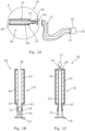
- FIGS 1A - 1C illustrate a first embodiment of a wetting mechanism 20 for use in wetting a tube 12 of a catheter 10.
- the catheter 10 includes the catheter tube 12, with the wetting mechanism 20 provided at a tip end (proximal end) 13 of the catheter tube 12 and a funnel 30 at a distal end 14 of the catheter tube 12.
- a sleeve 18 is provided between the wetting mechanism 20 and the funnel 30, enclosing the catheter tube 12 therebetween.
- the sleeve 18 is formed of a flexible material and is coupled at a first end to a housing 16 of the wetting mechanism 20 and at a second end to the funnel 30. In this way, the sleeve 18 defines an internal volume about the catheter tube 12 into which, in some instances, fluid may be introduced to wet the outer surface of the catheter tube 12.
- the catheter tube 12 has a tip end 13 and a distal end 14.
- the tip end 13 includes a tip for insertion of the catheter tube 12 into a canal, vessel, passageway, body cavity, etc. for removal of fluid therefrom.
- the catheter 10 comprises a male urinary catheter 10 with the tip configured for insertion into a male patient's bladder.
- the tip end 13 of the catheter tube includes an aperture 34 therein for allowing for fluid to enter the interior of the catheter tube 12.
- the distal end 14 of the catheter tube 12 is provided within the funnel 30. Specifically, the distal end 14 of the catheter tube 12 is located within the funnel 30 and opens into the funnel 30, which defines a fluid outlet 32 serving as an outlet for discharging fluid from within the catheter tube 12.
- the catheter tube 12 itself comprises a hydrophilic coating which acts to provide a low friction outer surface of the catheter tube 12 upon application of a wetting fluid 24.
- the wetting mechanism 20 includes a tubular housing 16 positioned (at least initially) at a tip end 13 of the catheter tube 12.
- the housing includes an inlet 43 and outlet 28 through which the catheter tube 12 may be moved, in use.
- the catheter tube 12 may be introduced into the housing 16 through the inlet 43, and may be moved out of the housing 16 through the outlet 28 to expose the tip end 13 thereof, i.e. for subsequent insertion into the urethra.
- a wetting applicator in the form of a foam conduit 40 is provided within the wetting chamber 23, and is configured to hold wetting fluid 24 therein and to control application of the fluid to the catheter tube 12, in use, as the catheter tube 12 is moved through the wetting chamber 23.
- the wetting chamber 23, and specifically the foam conduit 40 define a channel through the housing 16 through which at least a portion of the catheter tube 12 is able to be introduced and be moved therethrough.
- the channel is defined between the inlet 43 and outlet 28 of the housing 16 such that the catheter tube 12 is moved along the length of the foam conduit 40 in moving through the housing 16.
- the tip end 13 of the catheter tube 12 is moved out through the outlet 28 of the housing 16, the tip end 13 then becomes exposed for insertion by the user.
- the housing 16 then acts as a gripping element for the user to direct the catheter tube 12, in use, as the user may then use the housing 16 to easily direct the exposed tip end 13 of the catheter tube 12 without contacting the tube 12 directly.
- a wetting applicator of this type may advantageously ensure that the wetting fluid 24 is applied substantially evenly across the outer surface of the catheter tube 12, and reduce the prospect of any spillage. Further, having the wetting mechanism 20 provided as a gripping element for the catheter 10 improves the usability of the catheter 10 in terms of both the wetting action and ultimately the use of the catheter.
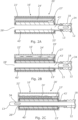
- wetting mechanism 20 is shown in Figures 2A - 2C . Specifically, these figures shown a wetting mechanism 20' configured similarly to wetting mechanism 20.
- Wetting mechanism 20' differs in that it comprises a housing 16' which further includes a holding chamber 22' which contains a volume of fluid 24 therein for wetting the catheter tube 12.
- the fluid 24' may be released from said holding chamber 22' into the wetting chamber 23', and specifically onto a wetting applicator in the form of a foam conduit 40' positioned within the wetting chamber 23'.
- the fluid 24' is released from the holding chamber 22' to the wetting chamber 23' through an opening 27' within the housing 16'.
- foam conduit 40 As with foam conduit 40, the foam conduit 40' is configured to hold fluid, but specifically here fluid 24' released into the wetting chamber 23' from the holding chamber 22'. Again, foam conduit 40' is configured to control application of the fluid to the catheter tube 12, in use, as the catheter tube 12 is moved through the wetting chamber 23'.
- the catheter tube 12 may be moved into and through the wetting chamber 23' via the inlet 43' in the same manner as wetting mechanism 20 described above, bringing the catheter tube 12 into contact with (and apply pressure to) the foam conduit 40'. This pressure causes release of the fluid 24' from the foam conduit 40', thereby wetting an outer surface of the catheter tube 12.
- the tip end 13 of the catheter tube 12 is moved out through an outlet 28' of the housing 16', the tip end 13 then becomes exposed for insertion by the user.
- the housing 16' then acts as a gripping element for the user to direct the catheter tube 12, in use, as the user may then use the housing 16' to easily direct the exposed tip end 13 of the catheter tube 12 without contacting the tube 12 directly.
- a wetting applicator of this type may advantageously ensure that the foam conduit 40' can be "topped up” with fluid 24' from the holding chamber 22' as the fluid held within the foam conduit 40' is released onto the catheter tube 12. This may ensure there is sufficient fluid to coat the entire length of the catheter tube 12, which may up to and possibly greater than 35cm.
- wetting mechanism 20' is shown in Figures 3A - 3C . Specifically, these figures show a wetting mechanism 120 configured in substantially the same way as wetting mechanism 20' shown in Figures 2A - 2C .
- Wetting mechanism 120 differs in that it comprises a fluid release control component in the form of a plug 126. As is described herein, the plug 126 is configured to control release of the fluid 124 from the holding chamber 122 to the wetting chamber 123, and specifically from the holding chamber 122 onto a wetting applicator in the form of foam conduit 140.
- the holding chamber 122 and wetting chamber 123 are fluidly connected to one another by an opening 127 in the housing 116.
- the fluid 124 is released from said holding chamber 122 into the wetting chamber 123, and onto the foam conduit 140, upon movement of the plug 126.
- a lip 129 is provided at an end of the plug 126 defining an interaction point for the user, specifically for the user to grip the lip 129 to provide leverage.
- the wetting mechanism 120 is provided in a first position with the plug 126 in a first position blocking the opening 127 ( Figure 3A ).
- the plug 126 is partially displaced from (i.e. pulled out from) the wetting chamber 123 to a second position ( Figure 3B ). In doing so, the plug 126 is moved to a position where the opening 127 is no longer blocked, allowing the fluid 124 to be released from the holding chamber 122 into the wetting chamber 123, and specifically onto the foam conduit 140.
- a notch 136 is provided on an outer circumferential surface of the plug 126 to define the extent to which the plug 126 can be removed from the wetting chamber 123. Specifically, the notch 136 provides a point of contact between the plug 126 and a circumferentially inwardly extending flange 38 at the end of the housing 116.
- the catheter tube 12 may be moved into and through the wetting chamber 123 via the inlet 143 in the same manner as wetting mechanisms 20, 20' described above, bringing the catheter tube 12 into contact with (and apply pressure to) the foam conduit 140.
- This pressure causes release of the fluid 124 from the foam conduit 140, thereby wetting an outer surface of the catheter tube 12.
- the tip end 13 of the catheter tube 12 is moved beyond the lip 129 in the plug 126, and out through an outlet 128 of the housing 116, the tip end 13 then becomes exposed for insertion by the user.
- the housing 116 then acts as a gripping element for the user to direct the catheter tube 12, in use, as the user may then use the housing 116 to easily direct the exposed tip end 13 of the catheter tube 12 without contacting the tube 12 directly.
- having the fluid 124 stored in a separate holding chamber 122 until (or as close as possible to) the point of use of the catheter 10 reduces the contact time of most components of the catheter 10 with the fluid 124, which may be advantageous in terms of shelf-life of the catheter 10.
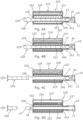
- Figures 4A - 4D illustrate a further embodiment of a wetting mechanism 220 for wetting an outer surface of the catheter tube 12.
- the wetting mechanism 220 comprises a housing 216 positioned (at least initially) at a tip end 13 of the catheter tube 12.
- the housing 216 again includes a holding chamber 222 which contains a volume of fluid 224 therein for wetting the catheter tube 12, and a wetting chamber 223 into which the fluid 324 may be released - specifically through an opening 227 within the housing 216.
- the wetting chamber 223 again defines a separate portion of the housing 216 and includes a foam conduit 240 defining a channel through the wetting chamber 223 through which at least a portion of the catheter tube 12 is able to be introduced and be moved therethrough.
- Wetting mechanism 220 differs in that it includes a plug 226 which is, at least initially, provided within the wetting chamber 223 and specifically within the channel defined by the foam conduit 240.
- a plug 226 which is, at least initially, provided within the wetting chamber 223 and specifically within the channel defined by the foam conduit 240.
- fluid 224 from the holding chamber 222 may be released through the opening 227 and on to the foam conduit 240, however, the plug 226 acts to effectively seal the wetting chamber 223 such that none of the fluid within the foam conduit 240, or indeed still within the holding chamber 222 can be released.
- the plug 226 also prevents the catheter tube 12 from being introduced into the wetting chamber 223. Accordingly, the plug 226 may prevent or at least reduce the likelihood of inadvertent activation of the wetting mechanism 220.
- the plug 226 is configured such that it can be fully removed from the wetting chamber 223, specifically by pulling the plug 226 out through outlet 228 in the housing 216.
- the plug 226 is provided with an enlarged rounded end portion 229 to assist with the user gripping the plug 226. Withdrawal of the plug 226 from the wetting chamber 223 unblocks the inlet 243 ( Figure 4C ).
- the catheter tube 12 may then be moved into and through the wetting chamber 223 via the inlet 243 in the same manner as wetting mechanisms 20, 120 described above, bringing the catheter tube 12 into contact with (and apply pressure to) the foam conduit 240. This pressure causes release of the fluid 224 from the foam conduit 140, thereby wetting an outer surface of the catheter tube 12.
- the housing 216 acts as a gripping element for the user to direct the catheter tube 12, in use, as the user may then use the housing 216 to easily direct the exposed tip end 13 of the catheter tube 12 without contacting the tube 12 directly.
- FIGS 5A - 5C illustrate a further embodiment of a wetting mechanism 320 according to the invention, for wetting an outer surface of the catheter tube 12.
- the wetting mechanism 320 comprises a housing 316 positioned (at least initially) at a tip end 13 of the catheter tube 12.
- the housing 316 again includes a holding chamber 322 which contains a volume of fluid 324 therein for wetting the catheter tube 12, and a wetting chamber 323 into which the fluid 324 may be released.
- Wetting mechanism 320 differs in that it includes a fluid release control component in the form of a container of fluid, specifically a sachet 326 which must be ruptured in order to release the fluid 324 therefrom and into the wetting chamber 323 and onto a wetting applicator in the form of a foam conduit 340.
- the foam conduit 340 is configured to hold fluid released thereon from the holding chamber 322 and is configured to control application of the fluid to the catheter tube 12, in use, as the catheter tube 12 is moved through the housing 316.
- the sachet 326 effectively defines the holding chamber 322.
- the foam conduit 340 defines the wetting chamber 323 through which the catheter tube 12 may be moved, in use.
- the sachet 326 is initially provided in the configuration shown in Figure 5A - i.e. intact, with the fluid contained therein.
- the sachet 326 is ruptured through a user applying an external force to the housing 316, i.e. by squeezing the housing 316 (as shown figuratively in Figure 5B ), which may be formed of a deformable material, or with a deformable region that can be squeezed.
- Rupture of the sachet 326 causes the fluid contained therein to be released into the wetting chamber 323, and specifically onto the foam conduit 340.
- the catheter tube 12 may then be moved through the wetting chamber 323 in contact with the foam conduit 340 and out through an outlet 328 at a distal end of the housing 316 to both wet the outer surface of the catheter tube 12 and expose the tip end 13 for insertion by the user.
- the housing 316 acts as a gripping element for the user to direct the catheter tube 12, in use.
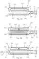
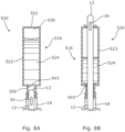
- Figures 6 - 7B illustrate a further embodiment of a catheter 410 and wetting mechanism 420 operable to wet a tube 412 of the catheter 410, in use.
- the catheter 410 includes the catheter tube 412, with the wetting mechanism 420 provided at a tip end 413 of the catheter tube 412 and a funnel 430 at a distal end 414 of the catheter tube 412.
- a sleeve 418 is provided between the wetting mechanism 420 and the funnel 430, enclosing the catheter tube 12 therebetween.
- the tip end 413 of the catheter 410 includes a tip for insertion of the catheter tube 412 into a canal, vessel, passageway, body cavity, etc. for removal of fluid therefrom.
- the catheter 410 comprises a male urinary catheter 410 with the tip configured for insertion into a male patient's bladder.
- the distal end 414 of the catheter tube 412 is provided within the funnel 430.
- the distal end 414 of the catheter tube 412 is located within the funnel 430 and opens into the funnel 430 which defines a fluid outlet 432 which serves as an outlet for discharging fluid from within the catheter tube 412.
- the funnel 430 is shaped to aid the user's control over the direction of discharge of the fluid from the catheter tube 412.
- the catheter tube 412 itself comprises a hydrophilic coating which acts to provide a low friction outer surface of the catheter tube 412 upon application of a wetting fluid.
- the wetting mechanism 420 is similar in configuration to wetting mechanism 120 described herein, and may be of the nature of, with the same features as the embodiment shown in Figures 3A - 3C . It includes a housing 416 positioned (at least initially) at the tip end 413 of the catheter tube 412.
- the housing 416 includes a holding chamber (not shown) which contains a volume of fluid therein for wetting the catheter tube 412. In use, and as is described herein, the fluid may be released from said holding chamber into a wetting chamber (not shown) of the housing 416 under the operation of a plug 426.
- an outer surface of the catheter tube 412 may be wetted using the fluid.
- the plug 426 is moveable from the position shown in Figure 7A (a first position) to the position shown in Figure 7B (a second position) to release the fluid from the holding chamber. Specifically, movement of the plug 426 between these positions may unblock an opening within the housing 416 or rupture a sachet, for example, to allow for the fluid to be released from the holding chamber into the wetting chamber and into / onto the foam conduit for subsequent application to the catheter tube 412.
- the plug 426 comprises a conical cross section, with a ridged exterior surface defining an interaction surface for the user.
- the housing 416 is also substantially conical in profile, and is positioned in such a way to define an hourglass-shaped configuration of the housing 416 and plug 426.
- This arrangement is particularly beneficial as it may allow for operation of the plug 426 using only one hand, as shown in Figures 7A and 7B .
- the user may grip the housing 416 and plug 426 between their thumb and forefinger, before using their thumb to push or "pop" the plug 426 upwards (in the orientation shown in the Figures) to release the fluid.
- the conical plug 426 has a cup like end, which eases location of the housing 416 over the tip of the penis to aid insertion of the catheter tube 412 into the urethra, in use.
- FIGS 8A - 8B illustrate a further embodiment of a wetting mechanism 520 for use in wetting catheter tube 12 of catheter 10.
- the wetting mechanism 520 includes a tubular housing 516 positioned (at least initially) at a tip end 13 of the catheter tube 12.
- the housing 516 includes an inlet 543 and outlet 528 through which the catheter tube 12 may be moved, in use. Specifically, the catheter tube 12 may be introduced into the housing 516 through the inlet 543, and may be moved out of the housing 516 through the outlet 528 to expose the tip end 513 thereof, i.e. for subsequent insertion into the urethra.
- Wetting mechanism 520 differs from the mechanisms described hereinabove in that it does not include a wetting applicator within the wetting chamber 523. Rather, the wetting fluid 524 is contained within the wetting chamber 523 itself, and the wetting fluid 524 is applied to catheter tube 12, in use, as the catheter tube 12 is moved through the wetting chamber 523.
- the wetting chamber 523 defines a channel through the housing 516 through which at least a portion of the catheter tube 12 is able to be introduced and be moved therethrough.
- the channel is defined between the inlet 543 and outlet 528 of the housing 516.
- the wetting mechanism 520 includes an inlet valve 550 provided at the inlet 543 and an outlet valve 552 provided at the outlet 528.
- the inlet and outlet valves 550, 552 advantageously seal the inlet and outlet 542, 528 preventing the wetting fluid 524 from leaking from the wetting chamber 523.
- the valves 550, 552 further allow for the passage of the catheter tube 12 through the wetting chamber 523.
- the inlet valve 550 is configured to allow the catheter tube 12 to be moved therethrough to introduce the catheter tube 12 into the wetting chamber 523 of the housing 516.
- the outlet valve 552 is configured to allow the catheter tube 12 to be moved therethrough to expose the catheter tube 12 for subsequent use/insertion by the user.
- the tip end 13 of the catheter tube 12 is moved out through the outlet 528 of the housing 516, the tip end 13 then becomes exposed for insertion by the user, and the housing 516 then acts as a gripping element for the user to direct the catheter tube 12, in use.
- the user may then advantageously use the housing 16 to easily direct the exposed tip end 13 of the catheter tube 12 without contacting the tube 12 directly.
- the wetting applicator may comprise a wicking material.
- the wicking material may be configured to provide a wicking action between the holding chamber (e.g. holding chambers 22, 122, 222, 322) and the wetting chamber (e.g. wetting chambers 23, 123, 223, 323), enabling the transfer of the fluid from the holding chamber into the wetting chamber for subsequent application to the catheter tube.
- This is enabled in the illustrated embodiments, for example, by having the wetting fluid 24, 124, 224, 324 in contact with the wetting applicator, or indeed by releasing the wetting fluid onto and in contact with the wetting applicator - e.g. through use of a fluid release control component.
- the wetting applicator may comprise a baffle arrangement which defines a plurality of subregions of the wetting applicator each configured to hold a portion of the fluid held within the wetting applicator.
- the baffle arrangement may define a plurality of subregions within the housing 16, 116, 216, 316, 416 e.g. within the wetting chamber 23, 123, 223, 323 of the housing 16, 116, 216, 316, 416 in which the fluid may reside and or be released into, e.g. from the holding chamber 22, 122, 222, 322.
Landscapes
- Health & Medical Sciences (AREA)
- Life Sciences & Earth Sciences (AREA)
- General Health & Medical Sciences (AREA)
- Public Health (AREA)
- Engineering & Computer Science (AREA)
- Anesthesiology (AREA)
- Biomedical Technology (AREA)
- Heart & Thoracic Surgery (AREA)
- Hematology (AREA)
- Animal Behavior & Ethology (AREA)
- Veterinary Medicine (AREA)
- Pulmonology (AREA)
- Biophysics (AREA)
- Epidemiology (AREA)
- Urology & Nephrology (AREA)
- Otolaryngology (AREA)
- External Artificial Organs (AREA)
- Media Introduction/Drainage Providing Device (AREA)
- Coating Apparatus (AREA)
- Materials For Medical Uses (AREA)
Claims (15)
- Benetzungsmechanismus (320) zum Benetzen eines Schlauches (12) eines Harnkatheters für einen Mann, wobei der Benetzungsmechanismus (32) umfasst:ein Gehäuse (316), welches ein Greifelement für den Katheter bildet, wobei das Gehäuse (316) dazu ausgestaltet ist, anfangs am oder proximal zum Spitzenende (13) des Katheterschlauchs (12) positioniert zu werden;wobei das Gehäuse (316) eine Benetzungskammer (323) umfasst, in die mindestens ein Teil des Katheterschlauchs (12) einführbar und durch diese hindurch bewegbar ist, um bei Gebrauch zumindest einen Teil des Katheterschlauchs (12) durch die Benetzungskammer (323) zu bewegen; undwobei der Benetzungsmechanismus (320) einen Benetzungsapplikator umfasst, der innerhalb der Benetzungskammer (323) angeordnet ist und dazu ausgestaltet ist, ein Fluid darin zu halten und das Fluid abzugeben, um den Katheterschlauch (12) beim Bewegen des Schlauchs durch die Benetzungskammer (323) zu benetzenwobei das Gehäuse (316) eine Haltekammer (322) umfasst, die ein Volumen eines Benetzungsfluids enthält, und wobei die Benetzungskammer (323) mit der Haltekammer (322) fluidisch verbunden oder verbindbar ist,wobei der Benetzungsmechanismus (320) eine Fluidabgabesteuerkomponente umfasst, die bei Gebrauch betreibbar ist, um die Abgabe des Fluids aus der Haltekammer (322) in die Benetzungskammer (323) zu steuern,dadurch gekennzeichnet, dass die Fluidabgabesteuerkomponente einen Behälter umfasst, der innerhalb der Haltekammer (322) positioniert ist oder diese zumindest teilweise definiert und das Fluid beinhaltet, und wobei der Behälter zerreißbar oder anderweitig zu öffnen ist, um das darin enthaltene Fluid abzugeben.
- Benetzungsmechanismus (320) nach Anspruch 1, wobei der Benetzungsapplikator unter Anwendung einer Kraft verformbar ist und wobei ein Verformen des Benetzungsapplikators eine Abgabe eines darin gehaltenen Fluids bewirkt.
- Benetzungsmechanismus (320) nach einem der vorhergehenden Ansprüche, wobei der Benetzungsapplikator ein Schwamm- oder Schaummaterial umfasst, welches das Fluid bei Gebrauch absorbieren kann.
- Benetzungsmechanismus (320) nach einem der vorhergehenden Ansprüche, wobei der Benetzungsapplikator ein Dochtmaterial umfasst, welches das Fluid bei Gebrauch zum Auftragen auf den Katheterschlauch (12) durch sich hindurchzieht.
- Benetzungsmechanismus (320) nach einem der vorhergehenden Ansprüche, wobei der Benetzungsapplikator einen Kanal innerhalb der Benetzungskammer (323) definiert oder die Benetzungskammer (323) des Benetzungsmechanismus (320) zumindest teilweise definiert.
- Benetzungsmechanismus (320) nach einem der vorhergehenden Ansprüche, wobei das Spitzenende (13) des Katheterschlauchs (13) zumindest anfangd außerhalb der Benetzungskammer (323) angeordnet ist.
- Benetzungsmechanismus nach Anspruch 6, wobei das Spitzenende (13) des Katheterschlauchs (12) zumindest anfangs innerhalb eines Einlasses der Benetzungskammer (323) gehalten wird.
- Benetzungsmechanismus (320) nach einem der vorhergehenden Ansprüche, wobei der Benetzungsmechanismus (320) der ausgestaltet ist, dass der Behälter beim Zusammendrücken, Verbiegen und/oder Biegen des Gehäuses (316) durch einen Benutzer bei Gebrauch zerrissen oder anderweitig geöffnet werden kann.
- Benetzungsmechanismus (320) nach einem der vorhergehenden Ansprüche, wobei die Fluidabgabesteuerkomponente einen beweglichen Verschluss umfasst, der zwischen einer ersten Position, in der dieser die Abgabe des Fluids aus der Haltekammer (322) an die Benetzungskammer (323) und/oder den Benetzungsapplikator verhindert, und einer zweiten Position, in der dieser die Abgabe des Fluids aus der Haltekammer (322) an die Benetzungskammer (323) und/oder den Benetzungsapplikator zulässt, bewegbar ist, wobei der Verschluss derart ausgestaltet ist, dass dieser zumindest teilweise aus der Benetzungskammer (323) des Benetzungsmechanismus (320) herausziehbar ist, wobei ein teilweises Herausziehen des Verschlusses einem Bewegen des Verschlusses aus der ersten Position in die zweite Position entspricht, und der Verschluss nicht vollständig aus dem Benetzungsmechanismus (320) herausgezogen werden kann.
- Benetzungsmechanismus (320) nach Anspruch 9, wobei der Verschluss linear bewegbar ist oder zwischen ersten und zweiten Positionen drehbar ist.
- Ein Katheter, umfassend:ein Katheterrohr (12), mit einem Spitzenende (13) und einem distalen Ende; undeinen Benetzungsmechanismus (320) nach einem der vorhergehenden Ansprüche, der an oder proximal zu dem Spitzenende (13) des Katheterschlauchs (12) funktionsfähig gekoppelt ist, um den Katheterschlauch (12) bei Gebrauch zu benetzen.
- Katheter nach Anspruch 11, wobei der Benetzungsapplikator eine Ablenkanordnung umfasst und der Katheterschlauch (12) eine hydrophile Komponente umfasst, in eine solche integriert oder mit einer solchen beschichtet ist.
- Katheter nach Anspruch 12, wobei die Ablenkanordnung mehrere Unterbereiche des Benetzungsapplikators definiert, die jeweils dazu ausgestaltet sind, einen Teil des im Benetzungsapplikator gehaltenen Fluids aufzunehmen.
- Katheter nach einem der Ansprüche 11 bis 13, wobei der Katheter ein Hamkatheter für einen Mann ist.
- Verfahren zum Benetzen eines Schlauches (12) eines Katheters unter Verwendung des Benetzungsmechanismus (320) nach einem der Ansprüche 1 bis 10, wobei das Verfahren umfasst:
Einführen des Spitzenendes (13) des Katheterschlauchs (12) in die Benetzungskammer (323) und Hindurchbewegen desselben, wodurch die Abgabe des Fluids aus dem Benetzungsapplikator bewirkt wird, wodurch zumindest ein Teil einer Außenfläche des Katheterschlauchs (12) benetzt wird.
Priority Applications (1)
| Application Number | Priority Date | Filing Date | Title |
|---|---|---|---|
| EP23208300.6A EP4295888B1 (de) | 2020-04-24 | 2021-04-23 | Benetzungsmechanismus für einen katheter |
Applications Claiming Priority (2)
| Application Number | Priority Date | Filing Date | Title |
|---|---|---|---|
| GBGB2006060.4A GB202006060D0 (en) | 2020-04-24 | 2020-04-24 | A wetting mechanism for a catheter |
| PCT/GB2021/050983 WO2021214480A1 (en) | 2020-04-24 | 2021-04-23 | A wetting mechanism for a catheter |
Related Child Applications (1)
| Application Number | Title | Priority Date | Filing Date |
|---|---|---|---|
| EP23208300.6A Division EP4295888B1 (de) | 2020-04-24 | 2021-04-23 | Benetzungsmechanismus für einen katheter |
Publications (3)
| Publication Number | Publication Date |
|---|---|
| EP4138972A1 EP4138972A1 (de) | 2023-03-01 |
| EP4138972B1 true EP4138972B1 (de) | 2023-11-22 |
| EP4138972C0 EP4138972C0 (de) | 2023-11-22 |
Family
ID=78221508
Family Applications (2)
| Application Number | Title | Priority Date | Filing Date |
|---|---|---|---|
| EP21724351.8A Active EP4138972B1 (de) | 2020-04-24 | 2021-04-23 | Benetzungsmechanismus für einen katheter |
| EP23208300.6A Active EP4295888B1 (de) | 2020-04-24 | 2021-04-23 | Benetzungsmechanismus für einen katheter |
Family Applications After (1)
| Application Number | Title | Priority Date | Filing Date |
|---|---|---|---|
| EP23208300.6A Active EP4295888B1 (de) | 2020-04-24 | 2021-04-23 | Benetzungsmechanismus für einen katheter |
Country Status (7)
| Country | Link |
|---|---|
| US (1) | US12053593B2 (de) |
| EP (2) | EP4138972B1 (de) |
| JP (1) | JP2023527635A (de) |
| CN (1) | CN115916313B (de) |
| AU (1) | AU2021259368A1 (de) |
| CA (1) | CA3176597A1 (de) |
| ES (1) | ES2973055T3 (de) |
Cited By (3)
| Publication number | Priority date | Publication date | Assignee | Title |
|---|---|---|---|---|
| US12053593B2 (en) | 2020-04-24 | 2024-08-06 | Convatec Limited | Wetting mechanism for a catheter |
| US12171956B2 (en) | 2020-04-24 | 2024-12-24 | Convatec Limited | Wetting mechanism for a catheter |
| US12515015B2 (en) | 2021-04-23 | 2026-01-06 | Convatec Limited | Intermittent catheter |
Families Citing this family (13)
| Publication number | Priority date | Publication date | Assignee | Title |
|---|---|---|---|---|
| WO2020251979A1 (en) | 2019-06-11 | 2020-12-17 | Convatec Technologies Inc. | Urine collection bags for use with catheter products, kits incorporating the same, and methods therefor |
| GB202006056D0 (en) | 2020-04-24 | 2020-06-10 | Convatec Ltd | A catheter |
| GB202006055D0 (en) | 2020-04-24 | 2020-06-10 | Convatec Ltd | A wetting mechanism for a catheter |
| EP4138969B1 (de) | 2020-04-24 | 2026-02-18 | ConvaTec Limited | Verpackung für ein medizinprodukt |
| EP4304441A4 (de) | 2021-03-10 | 2025-01-22 | Neptune Medical Inc. | Steuerung von robotischen dynamisch versteifenden medizinischen verbundstrukturen |
| US12564312B2 (en) | 2022-04-19 | 2026-03-03 | Neptune Medical Inc. | Managing and manipulating a long length robotic endoscope |
| WO2024069140A1 (en) * | 2022-09-26 | 2024-04-04 | Convatec Limited | A catheter assembly |
| CN119947776A (zh) * | 2022-09-26 | 2025-05-06 | 康沃特克有限公司 | 间歇式导管 |
| EP4605052A2 (de) * | 2022-10-19 | 2025-08-27 | ConvaTec Limited | Katheteranordnung |
| CN116999684B (zh) * | 2023-08-23 | 2025-03-28 | 苏州名创医疗科技有限公司 | 一次性吸引式输尿管支架管套装 |
| US12330292B2 (en) | 2023-09-28 | 2025-06-17 | Neptune Medical Inc. | Telescoping robot |
| WO2025202614A1 (en) * | 2024-03-25 | 2025-10-02 | Convatec Limited | Intermittent catheter |
| WO2025202613A1 (en) * | 2024-03-25 | 2025-10-02 | Convatec Limited | Intermittent catheter |
Family Cites Families (113)
| Publication number | Priority date | Publication date | Assignee | Title |
|---|---|---|---|---|
| JPS5216630Y2 (de) * | 1971-07-22 | 1977-04-14 | ||
| US3871358A (en) * | 1972-08-04 | 1975-03-18 | Olympus Optical Co | Guiding tube for the insertion of an admissible medical implement into a human body |
| US3898993A (en) * | 1973-09-25 | 1975-08-12 | Tokuso Taniguchi | Lubricated catheter |
| US4834711A (en) * | 1987-08-14 | 1989-05-30 | Greenfield Albert R | Dispensing appliance for insertion and maintenance of catheters, tubes and other articles of therapy |
| US5779624A (en) * | 1996-12-05 | 1998-07-14 | Boston Scientific Corporation | Sigmoid splint device for endoscopy |
| GB9921149D0 (en) * | 1999-09-07 | 1999-11-10 | United Bristol Healthcare Nhs | Lubricator for medical instrument |
| US6602244B2 (en) * | 2001-07-19 | 2003-08-05 | Hollister Incorporated | Lubricating and gripping device for urinary catheter package |
| DE10213411B4 (de) * | 2002-03-26 | 2006-10-26 | Hutzler, Walter | Katheter-Set |
| US20040074794A1 (en) * | 2002-10-18 | 2004-04-22 | Conway Anthony J. | Catheter wetting system and method |
| US20080051630A1 (en) * | 2003-12-16 | 2008-02-28 | Levey John M | Endoscopic Lubricating And Gripping Device |
| AU2006279587A1 (en) * | 2005-08-17 | 2007-02-22 | Colorado Catheter Company, Inc. | Catheterization assembly |
| US8328792B2 (en) * | 2005-10-27 | 2012-12-11 | C. R. Bard, Inc. | Enhanced pre-wetted intermittent catheter with lubricious coating |
| US7601158B2 (en) * | 2006-07-17 | 2009-10-13 | Colorado Catheter Company, Inc. | Devices for handling catheter assembly |
| US7963908B2 (en) * | 2007-10-29 | 2011-06-21 | Kevin Lindberg | Device to lubricate a penis or medical apparatus |
| EP2224988A2 (de) * | 2007-11-29 | 2010-09-08 | Coloplast A/S | Anordnung zur befeuchtung eines medizinischen gerätes |
| US10912917B2 (en) | 2009-12-23 | 2021-02-09 | C. R. Bard, Inc. | Catheter assembly/package utilizing a hydrating/hydrogel sleeve and method of making and using the same |
| AU2011227283A1 (en) * | 2010-03-16 | 2012-11-08 | Adapta Medical, Inc. | Catheter reservoir seals |
| DK2450076T3 (en) * | 2010-11-04 | 2017-12-04 | Curan Medical B V | Package with catheter |
| EP2468346B1 (de) | 2010-12-22 | 2020-11-04 | Dentsply IH AB | Katheteranordnung und Verfahren und System zur Herstellung der Anordnung |
| DK2688629T3 (da) | 2011-03-25 | 2023-01-09 | Hollister Inc | Urinopsamlingsenhed og fremgangsmåde til fremstilling deraf |
| BR112014002399B1 (pt) | 2011-08-29 | 2020-12-08 | Coloplast A/S | conjunto |
| HUE063482T2 (hu) | 2012-10-18 | 2024-01-28 | Hollister Inc | Párával hidratált orvosi eszköz alacsony felületi energiájú hüvellyel |
| DK177651B1 (en) | 2012-10-26 | 2014-02-03 | Mbh Internat A S | Method of preparing a ready-to-use urinary catheter and a catheter assembly for use in said method |
| CA2891115C (en) | 2012-11-12 | 2017-05-23 | Hollister Incorporated | Dry to the touch vapor hydration sleeve |
| US9931486B2 (en) | 2013-03-08 | 2018-04-03 | Coyloplast A/S | Catheter assembly |
| US9168354B2 (en) | 2013-03-14 | 2015-10-27 | Hollister Incorporated | Sleeveless urinary catheters with protective tip |
| EP3041560B1 (de) | 2013-09-02 | 2023-11-08 | Coloplast A/S | Katheteranordnung mit einfacher befestigung für tubus oder beutel |
| US10821209B2 (en) | 2013-11-08 | 2020-11-03 | Hollister Incorporated | Oleophilic lubricated catheters |
| AU2014360561B2 (en) * | 2013-12-04 | 2018-10-25 | Hollister Incorporated | Urinary catheter protective tips having a fluid reservoir |
| US10493230B2 (en) | 2013-12-20 | 2019-12-03 | Coloplast A/S | Intermittent urinary catheter |
| US10207076B2 (en) * | 2014-03-17 | 2019-02-19 | Hollister Incorporated | Intermittent catheters having hydration/gripper devices |
| US10561817B2 (en) | 2014-05-30 | 2020-02-18 | Hollister Incorporated | Flip open catheter package |
| DK3744381T4 (da) | 2014-12-29 | 2025-04-07 | Dentsply Ih Ab | Urinkateter med blød spids |
| EP3878484A1 (de) | 2015-04-16 | 2021-09-15 | Hollister Incorporated | Hydrophile beschichtungen und verfahren zur formung davon |
| CA2989055C (en) | 2015-06-26 | 2023-10-17 | Coloplast A/S | A urinary catheter assembly |
| GB2540125B (en) | 2015-06-29 | 2022-11-23 | Hunter Urology Ltd | Intermittent urinary catheterisation package and method of use |
| JP7171435B2 (ja) | 2015-12-17 | 2022-11-15 | コロプラスト アクティーゼルスカブ | システムの非常停止並びに肛門及び/又はストーマ洗腸の方法 |
| EP3184140B1 (de) | 2015-12-21 | 2021-10-06 | Dentsply IH AB | Katheter mit abgeschrägten drainagelöchern sowie verfahren und gerät zur solchen löcherformgebung |
| DK3693032T3 (da) | 2015-12-28 | 2022-05-16 | Dentsply Ih Ab | Hydrofil medicinsk indretning |
| US10850009B2 (en) | 2016-02-23 | 2020-12-01 | Hollister Incorporated | Medical device with hydrophilic coating |
| WO2017178030A1 (en) | 2016-04-12 | 2017-10-19 | Coloplast A/S | Catheter assembly with selectively vanishing protective sleeve |
| US10478871B2 (en) * | 2016-05-09 | 2019-11-19 | Lawrence Anthony Wiwi | Side-opening sleeve valve |
| KR101834784B1 (ko) * | 2016-05-20 | 2018-04-19 | (주)에스엠허스 | 의료용 튜브 홀더 |
| RU2754687C2 (ru) | 2016-06-30 | 2021-09-06 | Кнауф Гипс Кг | Система гипсокартонной конструкции с пружинной рейкой |
| EP3295977B1 (de) | 2016-09-16 | 2020-02-26 | Dentsply IH AB | Motorisiertes bewässerungssystem mit verbesserter flusssteurung |
| WO2018059637A1 (en) | 2016-09-27 | 2018-04-05 | Coloplast A/S | A hydrated catheter with sleeve |
| EP3308823B1 (de) | 2016-10-14 | 2022-12-07 | Dentsply IH AB | Kathetereinführhilfe, katheterset und anordnung |
| DE102017010234A1 (de) | 2016-11-25 | 2018-05-30 | Advanced Medical Balloons Gmbh | Vorrichtung für die repetitive Zu- und Ableitung von Substanzen für die medizinische Therapie, sowie Verfahren für die Herstellung einer Stuhlkontinenz durch intermittierende Colon-Lavage durch einen permanent platzierten, trans-analen Verschluss - bzw. Zugangskatheter |
| US9833592B1 (en) | 2016-12-13 | 2017-12-05 | Cure Medical Llc | Automatic gel applying container for an intermittent urinary catheter |
| HUE055716T2 (hu) | 2016-12-22 | 2021-12-28 | Dentsply Ih Ab | Motorizált katéter rendszer javított felfújás-szabályozással |
| DK3900752T3 (da) | 2017-01-20 | 2022-10-17 | Hollister Inc | Kateteranordning |
| DK3570899T3 (da) | 2017-01-20 | 2021-04-12 | Hollister Inc | Fremgangsmåder til sterilisering af en hydrofilt belagt medicinsk indretning |
| AU2018225486B2 (en) | 2017-02-21 | 2022-02-03 | Hollister Incorporated | Radiation activated gels that release fluids and assemblies containing the same |
| LT3618883T (lt) | 2017-05-04 | 2024-08-26 | Hollister Incorporated | Tepios hidrofilinės dangos ir jų formavimo būdai |
| EP3634561B1 (de) | 2017-06-09 | 2024-02-28 | Hollister Incorporated | Verpackungen für medizinprodukte |
| EP3421071B1 (de) | 2017-06-30 | 2023-09-20 | Wellspect AB | Dampfsterilisierte katheteranordnung und herstellungsverfahren |
| CA3069439C (en) | 2017-07-12 | 2023-10-03 | Hollister Incorporated | Ready-to-use urinary catheter assembly |
| BR112020002377A2 (pt) | 2017-08-17 | 2020-09-01 | Coloplast A/S | revestimento polimérico, métodos para sintetizar um revestimento polimérico e para revestir um cateter urinário, uso do revestimento polimérico, cateter urinário intermitente, e, kit. |
| GB201721956D0 (en) | 2017-12-27 | 2018-02-07 | Convatec Ltd | Female catheter locator tip |
| GB201721955D0 (en) | 2017-12-27 | 2018-02-07 | Convatec Ltd | Catheter wetting devices |
| US11285292B2 (en) | 2018-02-22 | 2022-03-29 | Cure Medical Llc | Closed system with intermittent urinary catheter feed |
| AU2019269674B2 (en) | 2018-05-17 | 2024-04-18 | Hollister Incorporated | Hydrophilic medical products and hydration mediums for hydrating the same |
| EP4245349A3 (de) | 2018-05-24 | 2023-11-15 | Wellspect AB | Harnkatheteranordnung mit befestigbarem griff |
| WO2020006527A1 (en) | 2018-06-28 | 2020-01-02 | Adapta Medical, Inc. | Catheters having low viscosity lubricant |
| DK180417B1 (en) | 2018-07-20 | 2021-04-22 | Coloplast As | INTERMITTING URINCATHER FITTING |
| US12201750B2 (en) | 2018-11-21 | 2025-01-21 | Hollister Incorporated | Hydration solutions containing volatile solutions and medical device products including the same |
| MX2021005900A (es) | 2018-11-21 | 2021-08-11 | Coloplast As | Una sonda urinaria intermitente. |
| WO2020131561A1 (en) | 2018-12-19 | 2020-06-25 | Hollister Incorporated | Hydrophilic coatings for medical devices |
| CN113164277B (zh) | 2018-12-20 | 2023-10-31 | 科洛普拉斯特公司 | 尿液收集袋 |
| CA3127706A1 (en) | 2019-02-08 | 2020-08-13 | Coloplast A/S | A urinary catheter |
| US11931524B2 (en) | 2019-02-25 | 2024-03-19 | Coloplast A/S | Urinary catheterisation aid |
| CA3067104C (en) | 2019-04-16 | 2021-06-22 | Cure Medical, Llc | Packaged precision-lubricated ready-to-use intermittent urinary catheter |
| CA3141410C (en) | 2019-05-22 | 2023-03-07 | Hollister Incorporated | Packaged hydrophilic medical devices |
| WO2020237073A1 (en) | 2019-05-22 | 2020-11-26 | Hollister Incorporated | Packaged hydrophilic medical products that are hydrated within the package and methods of making the same |
| WO2020251979A1 (en) | 2019-06-11 | 2020-12-17 | Convatec Technologies Inc. | Urine collection bags for use with catheter products, kits incorporating the same, and methods therefor |
| ES2947713T3 (es) | 2019-06-13 | 2023-08-17 | Hollister Inc | Productos de catéter urinario reutilizables |
| WO2020252045A1 (en) | 2019-06-13 | 2020-12-17 | Hollister Incorporated | Reusable urinary catheter kits |
| EP3990084B1 (de) | 2019-06-26 | 2025-09-24 | Coloplast A/S | Intermittierende harnkatheteranordnung mit sensorelement |
| WO2020259783A1 (en) | 2019-06-26 | 2020-12-30 | Coloplast A/S | Catheter comprising combined valve and sensor |
| CA3152630A1 (en) | 2019-08-27 | 2021-03-04 | Hollister Incorporated | Sleeved hydrophilic medical products |
| CA3158918A1 (en) | 2019-10-28 | 2021-05-06 | Hollister Incorporated | Urinary catheters and methods for preventing bacterial infections |
| WO2021086855A1 (en) | 2019-10-28 | 2021-05-06 | Hollister Incorported | Urinary catheters and methods for preventing bacterial infections |
| US20220347354A1 (en) | 2019-10-28 | 2022-11-03 | Hollister Incorporated | Urinary catheters and methods for preventing bacterial infections |
| EP4051329B1 (de) | 2019-10-28 | 2026-03-04 | Hollister Incorporated | Harnkatheter und verfahren zum vorbeugen bakterieller infektionen |
| CA3160638A1 (en) | 2019-11-08 | 2021-05-14 | Hollister Incorporated | Hydrophilic medical products and hydration mediums for hydrating the same |
| US10946168B1 (en) | 2019-11-18 | 2021-03-16 | Cure Medical Llc | Smart urinary catheter |
| US12144933B2 (en) | 2019-11-18 | 2024-11-19 | Convatec Inc. | Methods of monitoring urinary catheter usage |
| US20210162180A1 (en) | 2019-11-28 | 2021-06-03 | Meyer David GERSHBAUM | Catheter adapted briefs |
| WO2021118807A1 (en) | 2019-12-11 | 2021-06-17 | C.R. Bard, Inc. | An anti-microbial coated urethral plug for cauti reduction |
| EP4628108A3 (de) | 2020-03-13 | 2025-11-12 | Hollister Incorporated | Blasenkatheter mit verbessertem formerhalt sowie mit einfacher anwendung |
| US10912918B1 (en) * | 2020-03-23 | 2021-02-09 | Cure Medical Llc | Pre-lubricated female urinary catheter package |
| US20210299410A1 (en) | 2020-03-27 | 2021-09-30 | Wiesconcepts, LLC | Protective Sheath Assembly For A Method Of Evaluation And/Or Retrieving Pathological Samples From A Body Orifice, A Method For Administering An Anesthetic, Formulated Medication And/Or Chemotherapy Using A Protective Sheath Assembly |
| AU2021259368A1 (en) | 2020-04-24 | 2022-09-29 | Convatec Limited | A wetting mechanism for a catheter |
| GB202006056D0 (en) | 2020-04-24 | 2020-06-10 | Convatec Ltd | A catheter |
| GB202006055D0 (en) | 2020-04-24 | 2020-06-10 | Convatec Ltd | A wetting mechanism for a catheter |
| GB202006059D0 (en) | 2020-04-24 | 2020-06-10 | Convatec Ltd | A wetting mechanism for a catheter |
| EP4138969B1 (de) | 2020-04-24 | 2026-02-18 | ConvaTec Limited | Verpackung für ein medizinprodukt |
| EP4142843B1 (de) | 2020-05-01 | 2024-08-21 | Coloplast A/S | Intermittierende harnkatheteranordnung |
| EP4458402A3 (de) | 2020-05-12 | 2025-02-19 | Coloplast A/S | Zubehörvorrichtung für einen katheter |
| US11207206B2 (en) | 2020-05-14 | 2021-12-28 | Cm Technologies, Inc. | Fluid removal device |
| WO2021242745A1 (en) | 2020-05-26 | 2021-12-02 | Hollister Incorporated | One-piece intermittent catheters with variable thickness and handle feature |
| US12502506B2 (en) | 2020-05-27 | 2025-12-23 | Hollister Incorporated | Multi-flex urinary catheter |
| US20210370019A1 (en) | 2020-05-28 | 2021-12-02 | Strataca Systems Limited | Method of Treatment Using Negative Pressure Renal Therapy and Medicament(s) |
| US12599744B2 (en) | 2020-05-28 | 2026-04-14 | Hollister Incorporated | Drainage member design and ultrasonic welding method for attachment of catheter tube to drainage member |
| EP3932438A1 (de) | 2020-07-02 | 2022-01-05 | Dentsply IH AB | Hydrophile medizinische vorrichtungsanordnung |
| GB2596593B (en) | 2020-07-03 | 2025-02-19 | Uro Innovations Ltd | Female urine drainage device |
| CN116056746B (zh) | 2020-08-03 | 2026-03-17 | C·R·巴德股份有限公司 | 间歇导管组件 |
| EP3991773A1 (de) | 2020-10-27 | 2022-05-04 | Dentsply IH AB | Urinkatheteranordnung |
| CA3198152A1 (en) | 2020-11-20 | 2022-05-27 | Satwinder S. Panesar | Reduced-spill hydrophilic catheter product with foamed hydration liquid |
| WO2022118011A1 (en) | 2020-12-04 | 2022-06-09 | Convatec Limited | Packaged catheter assembly |
| WO2022118010A1 (en) | 2020-12-04 | 2022-06-09 | Convatec Limited | Packaged catheter assembly |
| US20220176069A1 (en) | 2020-12-04 | 2022-06-09 | Convatec Limited | Packaged catheter assembly |
| EP4255546B1 (de) | 2020-12-04 | 2024-03-06 | ConvaTec Limited | Verpackte katheteranordnung |
-
2021
- 2021-04-23 AU AU2021259368A patent/AU2021259368A1/en not_active Abandoned
- 2021-04-23 CA CA3176597A patent/CA3176597A1/en active Pending
- 2021-04-23 US US17/238,697 patent/US12053593B2/en active Active
- 2021-04-23 JP JP2022557787A patent/JP2023527635A/ja active Pending
- 2021-04-23 CN CN202180030773.2A patent/CN115916313B/zh active Active
- 2021-04-23 EP EP21724351.8A patent/EP4138972B1/de active Active
- 2021-04-23 ES ES21724351T patent/ES2973055T3/es active Active
- 2021-04-23 EP EP23208300.6A patent/EP4295888B1/de active Active
Cited By (3)
| Publication number | Priority date | Publication date | Assignee | Title |
|---|---|---|---|---|
| US12053593B2 (en) | 2020-04-24 | 2024-08-06 | Convatec Limited | Wetting mechanism for a catheter |
| US12171956B2 (en) | 2020-04-24 | 2024-12-24 | Convatec Limited | Wetting mechanism for a catheter |
| US12515015B2 (en) | 2021-04-23 | 2026-01-06 | Convatec Limited | Intermittent catheter |
Also Published As
| Publication number | Publication date |
|---|---|
| EP4295888A2 (de) | 2023-12-27 |
| JP2023527635A (ja) | 2023-06-30 |
| EP4138972A1 (de) | 2023-03-01 |
| CA3176597A1 (en) | 2021-10-28 |
| US12053593B2 (en) | 2024-08-06 |
| EP4295888C0 (de) | 2025-06-04 |
| CN115916313A (zh) | 2023-04-04 |
| EP4138972C0 (de) | 2023-11-22 |
| EP4295888A3 (de) | 2024-03-20 |
| EP4295888B1 (de) | 2025-06-04 |
| ES2973055T3 (es) | 2024-06-18 |
| US20210330938A1 (en) | 2021-10-28 |
| CN115916313B (zh) | 2025-08-01 |
| AU2021259368A1 (en) | 2022-09-29 |
Similar Documents
| Publication | Publication Date | Title |
|---|---|---|
| EP4138972B1 (de) | Benetzungsmechanismus für einen katheter | |
| EP4138971B1 (de) | Benetzungsmechanismus für einen katheter | |
| EP4138970B1 (de) | Benetzungsmechanismus für einen katheter | |
| EP3727549B1 (de) | Vorrichtung zum benetzen von kathetern | |
| US7571804B2 (en) | Package for a medical device | |
| US12064568B2 (en) | Catheter | |
| WO2021214480A1 (en) | A wetting mechanism for a catheter |
Legal Events
| Date | Code | Title | Description |
|---|---|---|---|
| STAA | Information on the status of an ep patent application or granted ep patent |
Free format text: STATUS: UNKNOWN |
|
| STAA | Information on the status of an ep patent application or granted ep patent |
Free format text: STATUS: THE INTERNATIONAL PUBLICATION HAS BEEN MADE |
|
| PUAI | Public reference made under article 153(3) epc to a published international application that has entered the european phase |
Free format text: ORIGINAL CODE: 0009012 |
|
| STAA | Information on the status of an ep patent application or granted ep patent |
Free format text: STATUS: REQUEST FOR EXAMINATION WAS MADE |
|
| 17P | Request for examination filed |
Effective date: 20221123 |
|
| AK | Designated contracting states |
Kind code of ref document: A1 Designated state(s): AL AT BE BG CH CY CZ DE DK EE ES FI FR GB GR HR HU IE IS IT LI LT LU LV MC MK MT NL NO PL PT RO RS SE SI SK SM TR |
|
| GRAP | Despatch of communication of intention to grant a patent |
Free format text: ORIGINAL CODE: EPIDOSNIGR1 |
|
| STAA | Information on the status of an ep patent application or granted ep patent |
Free format text: STATUS: GRANT OF PATENT IS INTENDED |
|
| DAV | Request for validation of the european patent (deleted) | ||
| DAX | Request for extension of the european patent (deleted) | ||
| INTG | Intention to grant announced |
Effective date: 20230628 |
|
| GRAS | Grant fee paid |
Free format text: ORIGINAL CODE: EPIDOSNIGR3 |
|
| GRAA | (expected) grant |
Free format text: ORIGINAL CODE: 0009210 |
|
| STAA | Information on the status of an ep patent application or granted ep patent |
Free format text: STATUS: THE PATENT HAS BEEN GRANTED |
|
| AK | Designated contracting states |
Kind code of ref document: B1 Designated state(s): AL AT BE BG CH CY CZ DE DK EE ES FI FR GB GR HR HU IE IS IT LI LT LU LV MC MK MT NL NO PL PT RO RS SE SI SK SM TR |
|
| REG | Reference to a national code |
Ref country code: GB Ref legal event code: FG4D |
|
| REG | Reference to a national code |
Ref country code: CH Ref legal event code: EP Ref country code: DE Ref legal event code: R096 Ref document number: 602021007101 Country of ref document: DE |
|
| REG | Reference to a national code |
Ref country code: IE Ref legal event code: FG4D |
|
| U01 | Request for unitary effect filed |
Effective date: 20231205 |
|
| U07 | Unitary effect registered |
Designated state(s): AT BE BG DE DK EE FI FR IT LT LU LV MT NL PT SE SI Effective date: 20231211 |
|
| PG25 | Lapsed in a contracting state [announced via postgrant information from national office to epo] |
Ref country code: GR Free format text: LAPSE BECAUSE OF FAILURE TO SUBMIT A TRANSLATION OF THE DESCRIPTION OR TO PAY THE FEE WITHIN THE PRESCRIBED TIME-LIMIT Effective date: 20240223 |
|
| PG25 | Lapsed in a contracting state [announced via postgrant information from national office to epo] |
Ref country code: IS Free format text: LAPSE BECAUSE OF FAILURE TO SUBMIT A TRANSLATION OF THE DESCRIPTION OR TO PAY THE FEE WITHIN THE PRESCRIBED TIME-LIMIT Effective date: 20240322 |
|
| U20 | Renewal fee for the european patent with unitary effect paid |
Year of fee payment: 4 Effective date: 20240320 |
|
| PG25 | Lapsed in a contracting state [announced via postgrant information from national office to epo] |
Ref country code: IS Free format text: LAPSE BECAUSE OF FAILURE TO SUBMIT A TRANSLATION OF THE DESCRIPTION OR TO PAY THE FEE WITHIN THE PRESCRIBED TIME-LIMIT Effective date: 20240322 Ref country code: GR Free format text: LAPSE BECAUSE OF FAILURE TO SUBMIT A TRANSLATION OF THE DESCRIPTION OR TO PAY THE FEE WITHIN THE PRESCRIBED TIME-LIMIT Effective date: 20240223 |
|
| PG25 | Lapsed in a contracting state [announced via postgrant information from national office to epo] |
Ref country code: RS Free format text: LAPSE BECAUSE OF FAILURE TO SUBMIT A TRANSLATION OF THE DESCRIPTION OR TO PAY THE FEE WITHIN THE PRESCRIBED TIME-LIMIT Effective date: 20231122 Ref country code: PL Free format text: LAPSE BECAUSE OF FAILURE TO SUBMIT A TRANSLATION OF THE DESCRIPTION OR TO PAY THE FEE WITHIN THE PRESCRIBED TIME-LIMIT Effective date: 20231122 Ref country code: NO Free format text: LAPSE BECAUSE OF FAILURE TO SUBMIT A TRANSLATION OF THE DESCRIPTION OR TO PAY THE FEE WITHIN THE PRESCRIBED TIME-LIMIT Effective date: 20240222 Ref country code: HR Free format text: LAPSE BECAUSE OF FAILURE TO SUBMIT A TRANSLATION OF THE DESCRIPTION OR TO PAY THE FEE WITHIN THE PRESCRIBED TIME-LIMIT Effective date: 20231122 |
|
| REG | Reference to a national code |
Ref country code: ES Ref legal event code: FG2A Ref document number: 2973055 Country of ref document: ES Kind code of ref document: T3 Effective date: 20240618 |
|
| PG25 | Lapsed in a contracting state [announced via postgrant information from national office to epo] |
Ref country code: CZ Free format text: LAPSE BECAUSE OF FAILURE TO SUBMIT A TRANSLATION OF THE DESCRIPTION OR TO PAY THE FEE WITHIN THE PRESCRIBED TIME-LIMIT Effective date: 20231122 |
|
| PG25 | Lapsed in a contracting state [announced via postgrant information from national office to epo] |
Ref country code: SK Free format text: LAPSE BECAUSE OF FAILURE TO SUBMIT A TRANSLATION OF THE DESCRIPTION OR TO PAY THE FEE WITHIN THE PRESCRIBED TIME-LIMIT Effective date: 20231122 |
|
| PG25 | Lapsed in a contracting state [announced via postgrant information from national office to epo] |
Ref country code: SM Free format text: LAPSE BECAUSE OF FAILURE TO SUBMIT A TRANSLATION OF THE DESCRIPTION OR TO PAY THE FEE WITHIN THE PRESCRIBED TIME-LIMIT Effective date: 20231122 Ref country code: SK Free format text: LAPSE BECAUSE OF FAILURE TO SUBMIT A TRANSLATION OF THE DESCRIPTION OR TO PAY THE FEE WITHIN THE PRESCRIBED TIME-LIMIT Effective date: 20231122 Ref country code: RO Free format text: LAPSE BECAUSE OF FAILURE TO SUBMIT A TRANSLATION OF THE DESCRIPTION OR TO PAY THE FEE WITHIN THE PRESCRIBED TIME-LIMIT Effective date: 20231122 Ref country code: CZ Free format text: LAPSE BECAUSE OF FAILURE TO SUBMIT A TRANSLATION OF THE DESCRIPTION OR TO PAY THE FEE WITHIN THE PRESCRIBED TIME-LIMIT Effective date: 20231122 |
|
| REG | Reference to a national code |
Ref country code: DE Ref legal event code: R097 Ref document number: 602021007101 Country of ref document: DE |
|
| PLBE | No opposition filed within time limit |
Free format text: ORIGINAL CODE: 0009261 |
|
| STAA | Information on the status of an ep patent application or granted ep patent |
Free format text: STATUS: NO OPPOSITION FILED WITHIN TIME LIMIT |
|
| 26N | No opposition filed |
Effective date: 20240823 |
|
| PG25 | Lapsed in a contracting state [announced via postgrant information from national office to epo] |
Ref country code: MC Free format text: LAPSE BECAUSE OF FAILURE TO SUBMIT A TRANSLATION OF THE DESCRIPTION OR TO PAY THE FEE WITHIN THE PRESCRIBED TIME-LIMIT Effective date: 20231122 |
|
| PG25 | Lapsed in a contracting state [announced via postgrant information from national office to epo] |
Ref country code: MC Free format text: LAPSE BECAUSE OF FAILURE TO SUBMIT A TRANSLATION OF THE DESCRIPTION OR TO PAY THE FEE WITHIN THE PRESCRIBED TIME-LIMIT Effective date: 20231122 |
|
| REG | Reference to a national code |
Ref country code: CH Ref legal event code: PL |
|
| PG25 | Lapsed in a contracting state [announced via postgrant information from national office to epo] |
Ref country code: CH Free format text: LAPSE BECAUSE OF NON-PAYMENT OF DUE FEES Effective date: 20240430 |
|
| PG25 | Lapsed in a contracting state [announced via postgrant information from national office to epo] |
Ref country code: IE Free format text: LAPSE BECAUSE OF NON-PAYMENT OF DUE FEES Effective date: 20240423 |
|
| U20 | Renewal fee for the european patent with unitary effect paid |
Year of fee payment: 5 Effective date: 20250319 |
|
| REG | Reference to a national code |
Ref country code: ES Ref legal event code: FD2A Effective date: 20250526 |
|
| PG25 | Lapsed in a contracting state [announced via postgrant information from national office to epo] |
Ref country code: ES Free format text: LAPSE BECAUSE OF NON-PAYMENT OF DUE FEES Effective date: 20240424 |
|
| PG25 | Lapsed in a contracting state [announced via postgrant information from national office to epo] |
Ref country code: CY Free format text: LAPSE BECAUSE OF FAILURE TO SUBMIT A TRANSLATION OF THE DESCRIPTION OR TO PAY THE FEE WITHIN THE PRESCRIBED TIME-LIMIT; INVALID AB INITIO Effective date: 20210423 |
|
| PG25 | Lapsed in a contracting state [announced via postgrant information from national office to epo] |
Ref country code: HU Free format text: LAPSE BECAUSE OF FAILURE TO SUBMIT A TRANSLATION OF THE DESCRIPTION OR TO PAY THE FEE WITHIN THE PRESCRIBED TIME-LIMIT; INVALID AB INITIO Effective date: 20210423 |
|
| PGFP | Annual fee paid to national office [announced via postgrant information from national office to epo] |
Ref country code: GB Payment date: 20260319 Year of fee payment: 6 |