EP4138650B1 - Vorrichtung und verfahren zur messung einer druckdifferenz - Google Patents
Vorrichtung und verfahren zur messung einer druckdifferenz Download PDFInfo
- Publication number
- EP4138650B1 EP4138650B1 EP21724354.2A EP21724354A EP4138650B1 EP 4138650 B1 EP4138650 B1 EP 4138650B1 EP 21724354 A EP21724354 A EP 21724354A EP 4138650 B1 EP4138650 B1 EP 4138650B1
- Authority
- EP
- European Patent Office
- Prior art keywords
- pressure
- pressure sensor
- tube
- stimulus
- sensor
- Prior art date
- Legal status (The legal status is an assumption and is not a legal conclusion. Google has not performed a legal analysis and makes no representation as to the accuracy of the status listed.)
- Active
Links
Images


Classifications
-
- A—HUMAN NECESSITIES
- A61—MEDICAL OR VETERINARY SCIENCE; HYGIENE
- A61B—DIAGNOSIS; SURGERY; IDENTIFICATION
- A61B5/00—Measuring for diagnostic purposes; Identification of persons
- A61B5/03—Measuring fluid pressure within the body other than blood pressure, e.g. cerebral pressure ; Measuring pressure in body tissues or organs
- A61B5/036—Measuring fluid pressure within the body other than blood pressure, e.g. cerebral pressure ; Measuring pressure in body tissues or organs by means introduced into body tracts
-
- A—HUMAN NECESSITIES
- A61—MEDICAL OR VETERINARY SCIENCE; HYGIENE
- A61B—DIAGNOSIS; SURGERY; IDENTIFICATION
- A61B5/00—Measuring for diagnostic purposes; Identification of persons
- A61B5/02—Detecting, measuring or recording for evaluating the cardiovascular system, e.g. pulse, heart rate, blood pressure or blood flow
- A61B5/021—Measuring pressure in heart or blood vessels
- A61B5/0215—Measuring pressure in heart or blood vessels by means inserted into the body
-
- A—HUMAN NECESSITIES
- A61—MEDICAL OR VETERINARY SCIENCE; HYGIENE
- A61B—DIAGNOSIS; SURGERY; IDENTIFICATION
- A61B5/00—Measuring for diagnostic purposes; Identification of persons
- A61B5/68—Arrangements of detecting, measuring or recording means, e.g. sensors, in relation to patient
- A61B5/6846—Arrangements of detecting, measuring or recording means, e.g. sensors, in relation to patient specially adapted to be brought in contact with an internal body part, i.e. invasive
- A61B5/6847—Arrangements of detecting, measuring or recording means, e.g. sensors, in relation to patient specially adapted to be brought in contact with an internal body part, i.e. invasive mounted on an invasive device
- A61B5/6848—Needles
-
- G—PHYSICS
- G01—MEASURING; TESTING
- G01L—MEASURING FORCE, STRESS, TORQUE, WORK, MECHANICAL POWER, MECHANICAL EFFICIENCY, OR FLUID PRESSURE
- G01L13/00—Devices or apparatus for measuring differences of two or more fluid pressure values
- G01L13/06—Devices or apparatus for measuring differences of two or more fluid pressure values using electric or magnetic pressure-sensitive elements
-
- A—HUMAN NECESSITIES
- A61—MEDICAL OR VETERINARY SCIENCE; HYGIENE
- A61B—DIAGNOSIS; SURGERY; IDENTIFICATION
- A61B2560/00—Constructional details of operational features of apparatus; Accessories for medical measuring apparatus
- A61B2560/02—Operational features
- A61B2560/0223—Operational features of calibration, e.g. protocols for calibrating sensors
-
- A—HUMAN NECESSITIES
- A61—MEDICAL OR VETERINARY SCIENCE; HYGIENE
- A61B—DIAGNOSIS; SURGERY; IDENTIFICATION
- A61B2562/00—Details of sensors; Constructional details of sensor housings or probes; Accessories for sensors
- A61B2562/02—Details of sensors specially adapted for in-vivo measurements
- A61B2562/0247—Pressure sensors
-
- A—HUMAN NECESSITIES
- A61—MEDICAL OR VETERINARY SCIENCE; HYGIENE
- A61B—DIAGNOSIS; SURGERY; IDENTIFICATION
- A61B2562/00—Details of sensors; Constructional details of sensor housings or probes; Accessories for sensors
- A61B2562/02—Details of sensors specially adapted for in-vivo measurements
- A61B2562/028—Microscale sensors, e.g. electromechanical sensors [MEMS]
Definitions
- the present invention relates to a device for measuring a pressure differential, and to associated methods of measuring a pressure differential.
- Compartments are regions within a human or animal body that are enclosed within connective fascia tissue.
- Compartment syndrome is a state of tissue swelling and increased pressure within a compartment.
- An elevated compartment pressure may oppose normal perfusion, which may cause disrupted blood supply associated with tissue necrosis and nerve damage.
- the pressure in a compartment may be a "static" pressure. That is, the pressure may be relatively constant over reasonable time intervals.
- CS may be acute or may be chronic (also known as exertional compartment syndrome).
- Acute compartment syndrome is typically associated with trauma to the affected compartment, such as in fractures or muscle injuries.
- Exertional compartment syndrome is often associated with repeated microtrauma related to physical activity.
- a clinical diagnosis of compartment syndrome is determined by measuring the relevant compartment pressure in a patient. If diagnosed promptly, a fasciotomy operation may be performed to remove seriously affected tissue, release the tissue pressure in the compartment, and later to close the surgical wound. Clinical indications for fasciotomy vary between authorities, however, in the UK a fasciotomy is required if:
- a fasciotomy is a major surgical procedure with an extended period of recovery (typically totalling several months) including considerable follow-up healthcare, and may lead to scarring.
- a false positive diagnosis i.e. a diagnosis of CS made when there is no CS results in needless operation, unnecessary costs of aftercare, and subjects the patient to additional risk and morbidity. It is therefore desirable to reduce the occurrence of false positive diagnoses.
- CS CS may be delayed, or worse, remain undiagnosed and untreated. If a diagnosis of CS is delayed, it may be necessary to perform an even more severe (acute) surgical procedure, which may necessitate amputation of the relevant body part, for example, amputation of a leg. Worse still, if CS is left undiagnosed and untreated, the condition can be fatal. A false negative diagnosis may further lead to the relevant healthcare provider to be subject to litigation and compensation costs. It is therefore highly desirable to avoid false negative diagnoses.
- the time available for prompt diagnosis is limited to a few hours, after which the more extreme measures are likely to be the only option to save the life of the patient.
- Known devices for measuring compartment pressure comprise a needle connected to a manometer line, or a column of fluid.
- a known device described in US4817629 , comprises a syringe, a pressure chamber having a flexible diaphragm, and means to penetrate the skin of the patient.
- the known device must be purged of air and calibrated (or zeroed) prior to insertion into the patient. It is necessary to zero known devices at an angle approximating the final angle of the device after introduction of the needle into the compartment or tissues. If the device is not fully purged of air, zeroed in this manner or if the angle of the device is varied, the measured pressures may not be accurate. An inaccurate pressure measurement could lead to either a false positive or a false negative diagnosis. It is desirable to improve the accuracy and reliability of a pressure monitoring device. It is also desirable to simplify the calibration process of a pressure monitoring device.
- Compartment pressure measurement should be performed during activity for a definitive diagnosis.
- known devices require the measurement step to be performed at the same angle as the calibration step, known devices are not suitable to measure compartment pressures during activity as errors may be introduced into the measurement if the patient moves. It is desirable to provide a reliable measurement of compartment pressures during activity (i.e. whilst the patient is moving).
- a “dynamic” pressure has a value that is continuously varying, for example changes in arterial pressure caused by the cardiac cycle.
- Cardiac procedures are intimately concerned with blood pressure levels in vascular structures and in one or more chambers of the heart during a cardiac procedure, and in following post-operative care.
- a typical management practice is to introduce one or several narrow bore manometer tubes at key points to allow local pressure at the open end of each tube to be measured. Under ideal conditions, this conventional arrangement provides the capability to sense local pressures.
- the tube can become blocked or contain one or more air bubbles. In either case this prevents the manometer line from providing an accurate pressure reading. It is desirable for a device to measure pressure levels with improved sensitivity. It is desirable for a device to be suitable for providing these measurements over an extended period of time without degradation or drift in measurements.
- Cerebral injuries are typically followed by surgery to arrest suspected internal bleeding. Clinicians must then monitor any internal swelling of brain tissue which is normally covered in cerebrospinal fluid (CSF). Swelling can cause internal pressure within the skull resulting in lowered or disrupted blood supply and consequently can lead to major damage, and possible permanent impairment.
- CSF cerebrospinal fluid
- a typical management practice is to introduce a narrow bore manometer tube which allows the pressure of the local CSF to be measured. The tube is arranged to be left in place and the wound closure is completed and sealed by the use of a purse suture tightened around the line tube. When the danger of swelling has passed the tube can be withdrawn and the purse suture closed.
- this conventional arrangement provides the capability to sense the pressure of local CSF.
- the tube can become blocked or filled with air bubbles. In either case this prevents the manometer line from providing an accurate pressure reading.
- Such a device could help clinicians to make a true negative diagnosis, which could avoid unnecessary operation, expense, extended period of hospitalisation and/or scarring for the patient.
- Such a device could also help to monitor internal cerebrospinal fluid pressure during head trauma surgery and in postoperative care.
- Such a device could also help to monitor internal blood pressure levels conditions during cardiac procedures and in postoperative care.
- Such a device could also support clinicians in the diagnosis and monitoring of a range of other medical conditions that may occur in clinical practice where there is a critical need to sense or measure internal pressures within the body.
- the present invention in at least some of its embodiments, seeks to address at least some of these problems, desires and needs.
- US 3703099 A discloses a pressure transducer including a pressure sensitive device having at least one part sensitive to a difference in pressure on each side thereof, a detector for detecting flexural strain induced in the sensitive part, and a distensible envelope providing a closure for and located adjacent to and unsecured to said pressure sensitive device.
- a device for measuring a pressure differential comprising:
- the device of the present invention has major advantages.
- the closed insertion portion prevents the internal bore from becoming blocked, and also prevents air bubbles from entering the internal bore.
- a closed insertion portion may facilitate sterilisation and provide fewer sites for bacterial growth.
- the closed insertion portion may allow the device to be re-used with a lower risk of infection or spread of infection.
- the presence of air bubbles does not affect the pressure measurement. This helps to improve the reliability of the pressure measurement and can help to reduce the risks of infection.
- the device may self-calibrate, for example, by virtue of the internal bore being in communication with ambient pressure. The device may be suitable to provide reliable pressure measurements even when the body is moving or active.
- the pressure differential may be a change in pressure differential.
- the internally facing region is in communication with ambient pressure via the internal bore.
- the exterior of the tube is in communication with an external pressure.
- the ambient pressure that the internal bore is in communication with is atmospheric pressure.
- the internal bore may be sealed and maintained at a fixed reference pressure. Measuring a pressure differential in respect of ambient pressure allows the device to self-calibrate and allows the pressure differential to be measured without using balanced hydraulics, manometer lines, and the like. Changes in atmospheric pressure may affect the pressure exterior of the tube and the pressure within the internal bore equally.
- the tube may be a needle.
- the tube may be a hypodermic needle.
- the tube may be a lancet.
- the insertion portion may be rigid.
- the tube may be rigid.
- the tube may be made from a metal, such as steel.
- the insertion portion may be flexible.
- the tube may be flexible.
- a flexible tube or insertion portion may facilitate insertion and positioning of the insertion portion.
- the tube may be made from a polymer, such as plastic.
- the tube may be constructed of several sections made of different materials.
- a section may be rigid.
- a section may be flexible.
- a rigid section may be a needle for penetration.
- Another section may be flexible for the convenient coupling to monitoring equipment. The sections may be joined to ensure that the integrity of the internal tube pressure is maintained.
- all sections of the tube may have a wall thickness sufficient to withstand the expected pressure within the body. This helps the insertion portion to maintain the diameter of the internal bore, so that the internal bore maintains communication with ambient pressure during and after insertion into a body.
- the tube may be resistant to kinking so that the communication between the internal bore and ambient pressure is not obstructed inadvertently.
- the insertion end may comprise a sharp tip.
- a sharp tip advantageously facilitates insertion of the insertion end into a body where appropriate by penetration.
- the insertion end may have a rounded tip.
- the insertion end may have a blunt tip.
- a blunt or rounded tip advantageously facilitates insertion into a body where appropriate, via a blood vessel for positioning within a cavity of the body such as a chamber of the heart, or when positioned by a surgeon before closing a surgery site using a purse suture or similar method to allow later removal after postoperative monitoring.
- the at least one pressure sensor may be located proximal to the insertion end. Locating the at least one pressure sensor proximal to the insertion end minimises the tube penetration depth required for pressure measurement.
- proximal is used here to mean closer to the insertion end than to the opening.
- the device may comprise a plurality of pressure sensors.
- the plurality of pressure sensors may be an array of pressure sensors.
- the plurality of pressure sensors may be arranged radially around the tube.
- the plurality of pressure sensors may be arranged axially along the tube.
- the at least one pressure sensor may have a resonant frequency.
- the resonant frequency of the at least one pressure sensor may correspond to the pressure differential between the exterior of the tube and the internal bore.
- the stimulus may cause at least one pressure sensor to resonate, for example, at its resonant frequency.
- the at least one pressure sensor When mechanically excited (e.g. when the stimulus is provided), the at least one pressure sensor may exhibit a resonant frequency dependent upon the differential pressure.
- At least two of the pressure sensors may have different resonant frequencies at the same pressure differential.
- the resonant frequency of each pressure sensor may depend on the pressure differential between the exterior of the tube and the internal bore. At least two of the pressure sensors may resonate at the same resonant frequency at different pressure differentials.
- a first pressure sensor may resonate at a first resonant frequency at a first pressure differential; and a second pressure sensor may resonate at the first resonant frequency at a second pressure differential, wherein the second pressure differential is greater than the first pressure differential.
- the resonant frequency of each pressure sensor may be tuned to resonate at a desired resonant frequency.
- the externally facing region of the pressure sensor may be substantially aligned (or flush) with the exterior of the tube.
- the pressure sensor may be shaped to substantially correspond to the profile of the exterior of the tube. For example, for a cylindrical tube, the externally facing region of the pressure sensor may be curved to match the cylindrical profile of the tube.
- the insertion portion may comprise at least one sealed aperture, in which each aperture is sealed by at least one pressure sensor.
- the sealed aperture may be sealed by two or more pressure sensors.
- the aperture may be a slot in the insertion portion.
- the aperture may be milled or machined into the insertion portion.
- the at least one aperture may be a plurality of apertures.
- the plurality of apertures may be arranged radially around the tube.
- the plurality of apertures may be arranged axially along the tube.
- the pressure sensor may be mounted on a mounting surface, such as a mounting membrane, across the aperture.
- the mounting surface may be suitable for deflecting or flexing when the pressure sensor is provided with the stimulus.
- the mounting surface may deflect or flex when the pressure sensor is vibrating, such as vibrating in a mechanical resonance.
- the at least one pressure sensor may comprise an electro-mechanical material or any other suitable material.
- the at least one pressure sensor may be a transducer.
- the at least one pressure sensor may comprise a piezoelectric pressure sensor.
- a piezoelectric pressure sensor may respond to an applied electrical stimulus to provide a mechanical resonance. This resonance may provide a measurable frequency response. The measurable frequency response may be correlated to the pressure differential between the exterior of the tube and the internal bore. This may be a static of dynamic pressure. For example, through calibration a measurable frequency response may be indicative of "static" pressure (i.e. a relatively constant pressure).
- a piezoelectric pressure sensor may respond to a changing external physical or mechanical stimulus to provide an electro-motive force. The external stimulus may be an applied stress caused from a changing pressure differential across the pressure sensor. By way of example, through calibration an electro-motive force response of sequential temporal samples may be indicative of "dynamic" pressure (i.e. a changing pressure).
- the at least one pressure sensor may comprise an electro-capacitive pressure sensor.
- the electro-capacitive pressure sensor may comprise a capacitive element.
- the capacitive element may comprise at least two electrodes.
- the at least two electrodes may be displaceable relative to each other.
- a first electrode may be fixed and an adjacent electrode may have mechanical freedom to be displaced relative to the first electrode.
- the at least two electrodes may be mounted such that parts may have mechanical freedom to be relatively displaced.
- the electro-capacitive pressure sensor may vibrate, for example, to generate ultrasound.
- the electro-capacitive pressure sensor may comprise a capacitive micromachined ultrasonic transducer (CMUT).
- CMUT capacitive micromachined ultrasonic transducer
- An electro-capacitive pressure sensor such as a CMUT, may respond to an applied electrical stimulus to provide a mechanical resonance. This resonance may provide a measurable frequency response. Through calibration, a frequency response may provide a measurable "static" pressure response. Sequential temporal samples may be indicative of "dynamic" pressure.
- An electro-capacitive pressure sensor may be substantially free of lead and/or offer high sensitivity.
- the at least one pressure sensor may comprise material that embeds one or more micro-electromechanical system (MEMS) devices.
- MEMS devices may include piezoelectric transducer components.
- MEMS devices may include capacitive micro-machined ultrasonic transducer (CMUT) components.
- CMUT capacitive micro-machined ultrasonic transducer
- the pressure sensor may have a low Q-factor.
- a low Q-factor provides a broad bandwidth of resonance.
- each of the pressure sensors may detect a small part of the whole bandwidth of interest.
- each of the pressure sensors in the plurality of pressure sensors may detect a discrete frequency band.
- Each pressure sensor may have a high Q-factor giving selectivity.
- the pressure sensor that provides the measurable response with the highest amplitude of vibration may be indicative of the pressure differential between the exterior of the tube and the internal bore.
- a single pressure sensor may embed one or more MEMS devices that incorporate a plurality of internal sensors together with a selection processing capability.
- the pressure sensor may be made from a ceramic material.
- the pressure sensor may be lead-containing.
- the piezoelectric pressure sensor may comprise lead zirconate titanate.
- the piezoelectric pressure sensor may be lead-free.
- the piezoelectric pressure sensor may comprise one or more of barium titanate, bismuth sodium titanate, bismuth potassium titanate, sodium niobate, potassium niobate, potassium sodium niobate, and poly(vinylidene difluoride) (PVDF).
- the stimulus may be an electrical stimulus.
- the pressure sensor may be configured to receive an electrical stimulus.
- the electrical stimulus may be an AC voltage.
- the electrical stimulus may be pulsed.
- the electrical stimulus may have any waveform.
- the electrical stimulus may impart resonance in a part of the pressure sensor.
- the pressure sensor may be electrically isolated from the tube. Keeping the pressure sensor isolated from the tube allows electrical stimulation of the pressure sensor without stimulating the tube.
- the externally facing region of the pressure sensor may comprise a coating.
- a coating isolates the pressure sensor from the body when inserted therein.
- the externally facing region may comprise an electrically insulating coating.
- An electrically insulating coating may isolate the current in the pressure sensor from the body (or body tissue) when inserted therein.
- the externally facing region may comprise a biocompatible coating.
- a biocompatible coating may enable the device to be inserted into body tissue for extended periods of time. This may be beneficial for pressure measurements over an extended period of time.
- the coating may be a polymer.
- the coating may be poly(p-xylylene).
- the measurable response may be an electrical response.
- the measurable response may be an ultrasound response.
- the measurable response may be indicative of an electrical impedance of the pressure sensor.
- the electrical impedance of the pressure sensor may vary with the pressure differential between the exterior of the tube and the internal bore.
- the measurable response may be an amplitude, such as an amplitude of vibration.
- the measurable response may be a resonant amplitude.
- the measurable response may be indicative of an amplitude, such as an amplitude of vibration.
- the measurable response may be indicative of a resonant amplitude.
- the measurable response may be indicative of a resonant frequency of the pressure sensor.
- the resonant frequency of the pressure sensor may vary with the pressure differential between the exterior of the tube and the internal bore. That is, the resonant frequency may correlate to the pressure differential.
- the resonant frequency may be a transverse mode of the pressure sensor.
- the resonant frequency may be a thickness mode of the pressure sensor. It will be appreciated that other vibrational modes are possible.
- the resonant frequency may be a composite of several vibration modes. Using the resonant frequency as an indication of the pressure differential can provide improved sensitivity of the device.
- the resonant frequency may be dependent on at least the length, width, thickness and material of the pressure sensor.
- the pressure sensor may have a resonant frequency between 0.1 MHz and 100 MHz.
- the resonant frequency may be between 1 MHz and 20 MHz.
- the resonant frequency may be between 1 MHz and 7 MHz.
- the resonant frequency may be between 7 MHz and 16 MHz.
- the resonant frequency may be between 16 MHz and 22 MHz.
- the resonant frequency may be between 1 MHz and 4 MHz.
- the resonant frequency of the pressure sensor may be between 0.1 MHz and 5 MHz, between 5 MHz and 20 MHz, between 20 MHz and 40 MHz, between 40 MHz and 60 MHz, between 60 MHz and 80 MHz, or between 80 MHz and 100 MHz.
- the resonant frequency may be between any combination of upper and lower limits provided above.
- the resonant frequency may be determined based on the desired use of the device.
- the measurable response may be indicative of a capacitance of the pressure sensor.
- the measurable response may be indicative of a change in capacitance of the pressure sensor.
- the measurable response may be indicative of a change in pressure differential between the exterior of the tube and the internal bore.
- the measurable response may be indicative of a change in electrical impedance of the pressure sensor.
- the tube may further comprise a non-insertion portion.
- the opening may be located at the non-insertion portion.
- the device may further comprise a user-holdable portion (or handle) which is in connection with the tube.
- the user-holdable portion may be in connection with the non-insertion portion.
- the user-holdable portion may house electrical components, such as the processor.
- the user-holdable portion may comprise a display for displaying the measured pressure differential.
- the internal bore may be in communication with ambient pressure via the user-holdable portion.
- the user-holdable portion may comprise one or more of a hand-grip, a finger-grip, and/or a thumb-grip.
- the hand-grip, finger-grip, and thumb-grip may help a user to operate the device.
- the device may be a handheld device.
- the device may be a portable device.
- the user-holdable portion may comprise a tube or needle penetration depth indicator for indicating a tube or needle penetration depth into the body.
- the tube or needle penetration depth indicator may assist a user to insert the tube or needle to a desired tube or needle penetration depth.
- the tube or needle penetration depth indicator may allow the user to re-insert the tube or needle to the same depth repetitiously if multiple pressure measurements are required. Recording the pressure measurements at the same depth helps to reduce experimental variances in repeated pressure measurements.
- the penetration depth indicator may comprise a measurement scale.
- the penetration depth indicator may comprise a pointer indicating the tube or needle penetration depth.
- the tube or needle penetration depth indicator may comprise one or more legs relatively moveable with respect to the tube or needle.
- the legs may be relatively moveable with respect to the user-holdable portion.
- the legs may slide in relative to the tube or needle upon insertion of the tube or needle into a body.
- the legs may comprise the measurement scale.
- the user-holdable portion may comprise a penetration restraint mechanism configured to limit the tube or needle penetration depth. It may be beneficial to limit the tube or needle penetration depth to prevent inserting the tube or needle too deep into the body.
- the penetration restraint mechanism may comprise a locking means, such as a friction clip.
- the locking means may clamp the legs of the penetration depth indicator, thereby preventing relative movement of the legs with respect to the user-holdable portion. Other locking means to restrict the movement of the legs with respect to the user-holdable portion may be contemplated.
- the locking means can retain the tube or needle at a stable injection depth. This is advantageous if the patient is required to move during pressure measurement.
- the user-holdable portion may comprise a fastening member for fastening the device to the body.
- the fastening member may allow the device to remain secure, stable and stationary when inserted into a body for an extended period of time. Using the fastening member to securely fasten the device to the body enables pressure measurements to be recorded whilst the body is moving, for example, during activity or clinical tests.
- the fastening member may facilitate the measurement of exertional compartment pressure.
- the fastening member may comprise one or more flanges. The flanges may be wing-tabs.
- the fastening member may be fastened to the body using an adhesive tape.
- the fastening member may comprise a belt or strap.
- the device comprises a processor configured to correlate the measurable response with the pressure differential between the exterior of the tube and the internal bore.
- the processor may use a calibration curve to correlate the measurable response with said pressure differential.
- the processor may be operable to provide a stimulus to the pressure sensor.
- the processor may be electrically connected to the pressure sensor via wires disposed in the internal bore.
- the wires may be disposed outside of the internal bore.
- the wires may be electrically insulated from the tube.
- the wires may have a length of less than 500 mm.
- the wires may have a length of less than 200 mm.
- the wires may have a length of less than 100 mm. Wires with a shorter length may provide improved electrical impedance measurements due to their lower reactive electrical load.
- the processor may be electrically connected to the pressure sensor via a wireless connection.
- the processor may be housed within the user-holdable portion.
- the processor may be housed within a central processing unit.
- the central processing unit may process the measureable responses from one or more devices.
- the tube may be a needle.
- the tube may have a cross-sectional diameter of between 0.1 mm and 5 mm.
- the tube may have a cross-sectional diameter of between 0.5 mm and 2.1 mm.
- the tube may have a length of between 10 mm and 150 mm.
- the tube may have a length of between 50 mm and 80 mm.
- the pressure sensor may have a cross-sectional dimension between 0.1 mm and 25 mm.
- the pressure sensor may have a cross-sectional dimension of between 0.2 mm and 10 mm.
- the pressure sensor may have a cross-sectional dimension of between 1 mm and 5 mm.
- the externally facing region may have a cross-sectional dimension of between 1 mm and 3 mm. These cross-sectional dimensions may be a cross-sectional length or a cross-sectional width.
- the pressure sensor may have a thickness of less than 1 mm.
- the pressure sensor may have a thickness of less than 0.5 mm.
- the pressure sensor may have a thickness of less than 0.27 mm.
- the thickness of the pressure sensor may be defined as the distance between the internally facing region and the externally facing region.
- kit of parts comprising: the device according to any previous claim; and an insertion site guide for indicating a tube insertion site.
- the insertion site guide may comprise a wearable sleeve or sheet.
- the insertion site guide may indicate the position of muscular compartments. This may allow a user of the device to insert the device into the same location repetitiously. This is particularly beneficial for identifying the correct compartment location, and for reliably inserting the tube or needle into the same location if multiple tube or needle insertions are required.
- a third aspect of the invention there is a method of measuring a pressure differential using the device according to the first aspect, the method comprising the steps of:
- the pressure differential may be a change in pressure differential.
- the stimulus may be an electrical stimulus.
- Providing a stimulus, such as an electrical stimulus, to the pressure sensor can improve the sensitivity of the device. This allows the pressure sensor to be miniaturised whilst maintaining acceptable levels of sensitivity.
- the method may further comprise the step of calibrating the device.
- the step of calibrating the device may comprise the sub-steps of:
- the stimulus used in the calibration step may be an electrical stimulus.
- the calibration step uses ambient pressure as a reference pressure.
- the ambient pressure may be atmospheric pressure. This eliminates the necessity to use balanced syringes, manometer lines and the like to calibrate the device.
- the device may self-calibrate. That is, a change in the ambient pressure will affect the pressure within the internal bore and the pressure within a body (when inserted therein) to the same extent. Therefore, the pressure differential is unaffected and drifts in pressure measurement are avoided.
- the method may further comprise the step of applying an electrical stimulus to the pressure sensor.
- the step of measuring the measurable response may be performed at least partially during the step of applying the electrical stimulus to the pressure sensor.
- the stimulus may be an alternating electrical stimulus, such as an AC voltage.
- the stimulus may be a pulsed electrical stimulus.
- the stimulus may be an ultrasound stimulus.
- the stimulus may cause the pressure sensor to vibrate.
- the stimulus may cause the pressure sensor to resonate at a resonant frequency.
- the frequency of the stimulus may be varied.
- the frequency of the stimulus (e.g. electrical stimulus) may be increased or decreased from a first frequency to a second frequency, for example, as a frequency sweep.
- the frequency of the stimulus may be constant.
- the stimulus may comprise a frequency that is substantially the same as the resonant frequency of the pressure sensor.
- the stimulus may have a frequency between 0.1 MHz and 100 MHz.
- the stimulus may have a frequency of between 1 MHz and 7 MHz.
- the stimulus may have a frequency of between 1 MHz and 4 MHz.
- the stimulus may have a frequency of between 16 MHz and 22 MHz.
- the frequency of the stimulus may be between 0.1 MHz and 20 MHz, 20 MHz and 40 MHz, between 40 MHz and 60 MHz, between 60 MHz and 80 MHz, or between 80 MHz and 100 MHz.
- the frequency of the stimulus may be between any combination of upper and lower limits provided above.
- the first and second frequencies may be any combination of the upper and lower limits provided above.
- the frequency (or range of frequencies) of the stimulus may be dependent upon the previously measured pressure differential.
- the frequency of the stimulus may be varied in a localised range comprising a frequency that correlates to the pressure differential of the previous measurement.
- the frequency of the stimulus may be varied in a localised range comprising a frequency that provided the maximum resonance of the previous measurement.
- the localised range may be about ⁇ 5 Hz, ⁇ 2 MHz, ⁇ 1 MHz, or ⁇ 0.5 MHz of the frequency that correlated to the pressure differential of the previous measurement.
- the frequency of the stimulus may start at the frequency that correlated to the pressure differential of the previous measurement and step outwardly (i.e. higher and lower) therefrom until the current pressure differential is determined, for example, until a new maximum resonance value is measured.
- Using a localised range of stimulus frequencies can help reduce power consumption of the device and can extend battery life.
- the measurable response may be an ultrasound response.
- the measurable response may be an electrical response.
- the measurable response may be indicative of an electrical impedance of the pressure sensor.
- the measurable response may be indicative of a resonant frequency of the pressure sensor.
- the measurable response may be indicative of a change in electrical impedance of the pressure sensor.
- the method may further comprise the steps of:
- the steps of providing the stimulus and removing the stimulus may be alternated repeatedly whilst measuring the measurable response. This can enable both static and dynamic pressures to be measured with a reduced power consumption.
- the measurable response may be measured at a sampling rate of between 6 samples per hour and 25 samples per second.
- the sampling rate may be between 1 sample per minute and 10 samples per second.
- the sampling rate may be at least 10 times faster than the arterial pulse rate.
- the pressure differential between the exterior of the tube and the internal bore may be between - 200mmHg and +200mmHg.
- the pressure differential may be between -120mmHg and +120mmHg.
- the pressure differential may be between 0 mmHg and +60mmHg.
- the pressure exterior to the tube may be a compartment pressure, spinal cord pressure, intracranial pressure, interstitial pressure, arterial pressure, venous pressure, and/or atmospheric pressure.
- the body may have a body pressure that is isolated from ambient pressure.
- the body may be a pressurised chamber, such as a tyre, a sealed chamber, such as a sealed reaction vessel, or a low pressure chamber, such as a vacuum chamber.
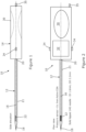
- FIGS 1, 2 and 2A illustrate a device (shown generally at 10) for measuring a pressure differential in a body according to a first embodiment of the invention.
- the device 10 comprises a tube 12 and a handgrip (or handle) 14.
- the tube 12 is hollow, comprising an internal bore 16, a closed first end (or tip) 18, and an open second end 20.
- the bore 16 is delimited by walls 21 and the closed first end 18.
- the tube 12 is a needle.
- the closed first end 18 is sharp to allow the needle 12 to be inserted into a patient body by penetrating body tissue. In other embodiments, the closed first end is blunt.
- the internal bore 16 is maintained at ambient atmospheric pressure.
- the open second end 20 is in open communication with the atmosphere, and therefore the internal bore 16 maintained at ambient atmospheric pressure.
- the second end 20 of the needle 12 extends into the handgrip 14.
- the handgrip 14 comprises breather holes (or slits) to allow the open end 20 to be exposed to the atmosphere. The breather holes ensure that the internal bore 16 remains in communication with atmospheric pressure.
- the internal pressure (P bore ) in the bore 16 is maintained at atmospheric pressure due to the open second end 20.
- the pressure in the bore 16 of the needle 12 is used as a known reference pressure.
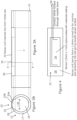
- the needle 12 further comprises a pressure sensor 22, shown in more detail in Figures 3A, 3B and 4 .
- the sensor 22 is set into a slot or other aperture 23 formed in the walls 21 of the needle 12.
- the needle 12 comprises a plurality (or array) of discrete pressure sensors set into a single slot.
- the needle 12 comprises a plurality of slots with one or more sensors set into each slot.
- each sensor is optimised to detect a specific pressure range.
- the slot 23 is conveniently formed using known machining (or electro-machining) methods.
- the sensor 22 is shaped to be substantially flush with the walls 21 so as not to obstruct or impede the movement of the needle during insertion. That is, the walls and sensor provide a substantially smooth outer surface during needle insertion.
- the sensor 22 is a sector of a hollow cylinder in shape. The sector may be up to a maximum of a hemi-cylinder in some embodiments. Other two- or three-dimensional geometries of the sensor, such as square, rectangular, ellipse, circular, oval, or annular may be employed in other embodiments.
- the sensor has a geometry optimised to detect specific forcing modes, for example a "hoop" stress component.
- the sensor has a longitudinal component to detect a pressure pulse passing along a vessel.
- the sensor 22 comprises an active surface 24 and a non-active surface 26.
- the sensor has an externally facing region and an inwardly facing region.
- the active surface 24 of the sensor 22 comprises an externally facing active surface 24a and an internally facing active surface 24b.
- the externally facing active surface 24a faces outwardly, and is in communication with a pressure exterior to the bore 16 of the needle 12. That is, the externally facing active surface 24a is in communication with an external load pressure (P ext ).
- P ext external load pressure
- the external active surface 24a is in communication with the body interior (e.g. body tissue).
- the external pressure corresponds to the pressure in the body interior.
- the body pressure may be a compartment pressure.
- the external active surface 24a comprises a coating 25.
- the coating 25 physically isolates the active surface 24 from the body, for example, isolating the chemical components of the sensor from the body interior. This is of particular benefit if the sensor 22 comprises a potentially harmful chemical, such as a lead-containing material.
- the coating 25 (or an additional coating layer) electrically isolates the active surface 24 from the body.
- the coating is a polymer coating. In some embodiments, the polymer is poly(p-xylylene).
- the internally facing active surface 24b faces inwardly, and is in communication with the internal pressure (P bore ) within the bore 16.
- a pressure differential (P ext -P bore ) exists between the external pressure (P ext ) and the internal pressure (P bore ) in the bore 16.
- the principle sensing action of the pressure sensor arises due to flexure in the pressure sensor as the pressure differential (P ext -P bore ) varies. This flexure can provide a measurable response to be generated.
- the non-active surface 26 is attached to the walls 21 of the needle 12.
- a non-conductive adhesive is used.
- the active surface 24 and the walls 21 are electrically isolated.
- the active surface 24 of the sensor 22 comprises an electro-mechanical material or material that embeds one or more micro-electromechanical system (MEMS) devices.
- MEMS micro-electromechanical system
- the active surface 24 comprises a piezoelectric material or transducer.
- the piezoelectrical material has a low Q-factor. In other embodiments, for example, where a plurality of sensors is deployed each sensor may have a high Q-factor.
- the sensor 22 comprises a ceramic.
- the piezoelectric material is an intermetallic inorganic polycrystalline ceramic compound.
- the piezoelectric material is lead-containing, such as lead zirconate titanate.
- the piezoelectric material does not containing lead, and, for example, may be formed from barium titanate, bismuth sodium titanate, bismuth potassium titanate, sodium niobate, potassium niobate, and/or potassium sodium niobate.
- the sensor 22 comprises poly(vinylidene difluoride) (PVDF). PVDF exhibits long-term biocompatibility.
- a piezoelectric material produces an electrical signal in response to a change in external physical or mechanical stimulus.
- the electrical signal may be an electro-motive force (or a voltage) which changes in response to a change in the external stimulus, such as a change in applied mechanical force.
- the external stimulus may, for example, be an applied stress caused from a change in pressure differential across the sensor. A change in applied stress may cause the impedance of the piezoelectric material to change. However, the measurable change in voltage (or impedance) will decay very rapidly if the change in external physical or mechanical stimulus ceases.
- a piezoelectric sensor also responds to an applied electrical stimulus.
- an applied electrical stimulus (of appropriate frequency) may cause a piezoelectric sensor to resonate at a characteristic resonant frequency.
- the resonant frequency is dependent upon the pressure differential across the sensor.
- the resonant frequency may be determined using known processing techniques.
- the senor 22 it is preferable for the sensor 22 to be formed from a piezoelectric material that has a narrow resonant peak (i.e. a high Q factor). This helps to improve the sensitivity of the device 10. That is, a change in pressure differential can be detected as a well-defined change in resonant frequency. In other embodiments, a low Q-factor is used to give a broad range of resonant frequency with good sensitivity. It may be preferable to use a Q-factor having an intermediate value. This compromise provides a broad based of resonance, whilst giving a higher resonance response.
- a narrow resonant peak i.e. a high Q factor
- the impedance of a piezoelectric sensor is also dependent upon the pressure differential. Measuring the electrical impedance at a particular frequency may be correlated with a pressure differential across the sensor.
- Contact wires 28 form an electrical contact between the sensor 22 and processor located in the handgrip 14.
- the processor correlates electrical signals (or responses) from the sensor 22 with a pressure differential (P ext -P bore ).
- the contact wires 28 are disposed within the bore 16. However, in other embodiments, the contact wires are disposed on the outside of the bore. The contact wires 28 are electrically isolated from the walls 21.
- the contact wires 28 relay electrical signals between the processor (not shown) and the sensor 22.
- the contact wires 28 allow electrical power or an electrical stimulus (including electrical pulses or other waveforms) to be applied to the sensor 22.
- the contact wires 28 also allow electrical signals generated by the sensor 22 to be measured by the processor.
- the processor is disposed within the bore 16. The invention is not limited by location of the processor.
- the processor provides one or more of signal amplification, signal conditioning, and/or analogue to digital encoding.
- the processor is wirelessly connected to the sensor 22.
- the processor is disposed in a central processing unit, suitable for data storage and data analysis of one or more devices 10.
- the central processing unit may be configured to store a timed sequence of regular measurements to track trends in pressure over time.
- the central processing unit may provide power, enable control of the device 10, and display pressure readings.
- the processor provides an alert if the measured pressure, such as a compartment pressure or intracranial pressure, exceeds a pre-determined threshold value set by the user.
- the central processing unit is configured for bidirectional communication with the pressure sensor.
- the central processing unit may provide additional facilities for comparative display of a plurality of pressure values obtained from a plurality of pressure measurements.
- the display may show raw or processed data.
- the central processing unit may comprise a user interface which provides individual control to one or more devices connected to the central processing unit.
- the central processing unit may be configured to be a fixed installation, for example at a bedside.
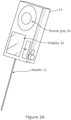
- the handgrip 14 may further comprise a thumb grip 30, a display 32, and measurement controls 34 ( Figure 5 ).
- the thumb grip 30 provides additional support and comfort to the user.
- Embodiments comprising a handgrip 14 may be portable devices.
- the display 32 provides a read-out of the measured pressure differential and other parameters, which may be measured simultaneously, such as arterial pulse rate.
- the display includes an alert system dependent upon the measured pressure differential.
- the display flashes to indicate the pulse rate.
- the measurement controls 34 allow the user to initiate the device, zero the device, and/or operate the device in the desired mode, for example, providing a switch between stimulated and passive operational modes as described below.
- the measurement controls 34 allow the sampling rate to be adjusted by the user.
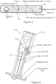
- the device 210 further comprises a means for indicating and controlling the needle penetration depth on insertion into a body.
- the same reference numerals as used in previous Figures have been used in Figure 6 to refer to features that are identical.
- the second embodiment is formed in a similar manner to the first embodiment.
- the handgrip 214 further comprises a pedestal 236.
- the pedestal 236 is a substantially circular band, having the needle 12 disposed at its centre.
- the diameter of the pedestal 236 is optionally the same width as the handgrip 214.
- the invention is not limited by the geometry of the pedestal 236.
- the pedestal 236 further comprises legs 238 configured to slide in complementary grooves in the handgrip 214 when the needle 12 is inserted into a body.
- the legs 238 comprise a scale 242 and a pointer 244.
- the movement of the legs 242 in the grooves allows the depth of the penetration to be determined using the scale 242 and pointer 244.
- This configuration beneficially provides a precise indication of needle penetration and allows a user, such as a clinician, to repeatedly insert the needle 12 to the same desired depth for long-term or repeated pressure measurements.
- the handgrip 214 further comprises a locking means, such as a friction clip or lock tab 246, to restrain the movement of the legs, thereby securing the legs 238 at a fixed, desired position. This beneficially prevents unwanted further movement or penetration of the needle when the required depth is attained. That is, the friction clip 246 limits the needle penetration depth into a body.
- a locking means such as a friction clip or lock tab 246, to restrain the movement of the legs, thereby securing the legs 238 at a fixed, desired position. This beneficially prevents unwanted further movement or penetration of the needle when the required depth is attained. That is, the friction clip 246 limits the needle penetration depth into a body.
- the device 210 further comprises a fixation means or an anchor 248 in the form of wing-tabs.
- the anchor 248 provides a surface allowing the device 214 to be fixed or attached to the body, for example, by adhesive tape or a strap.
- the device 10 is first initiated by supplying a power supply to the processor whilst the device is outside of a patient body.
- the power supply provides an electrical source to electronic components in the device, such as the sensor 22 and the processor.
- the supplied power enables pressure measurement, data processing and display.
- a pull-tab initially prevents contact between the power supply and the processor so that the electrical circuit is incomplete.
- the device 10 is initiated by closing an electrical contact between the power supply and the processor, thereby completing the electrical circuit.
- the device is initiated by removing the pull-tab to complete the electrical circuit.
- the electrical contact is formed on removal of a suitable needle shield or sheath. Removal of the needle shield completes the electrical circuit and initialises the device. This beneficially necessitates that the device is initiated, and calibrated, prior to insertion into a body.
- Other embodiments employ other known methods of completing the electrical circuit, such as connecting an external power source, using a mechanical switch, button, or other known method of supplying power to electrical circuitry.
- Devices 10, 210 used in medical applications may be single-use devices to avoid contamination and to reduce the risk and spread of infection.
- the power may be supplied by a battery, which continuously supplies power until the battery is fully discharged.
- a pull-tab initialisation mechanism provides a one-time initiation method so that the battery may continuously supply power to the electrical circuitry until the battery has fully discharged. This is particularly beneficial for disposable or single-use devices, and helps to prevent re-use, which could lead to an increased risk of infection.
- Some embodiments of the device may be used multiple times, with sterilisation techniques used between each use. It is beneficial for a multiple use device to have power switches and/or replaceable/rechargeable batteries to conserve battery power when not in use.
- an auto-calibration (or self-calibration) step is performed, as detailed below.
- the external pressure (P ext ) and the internal bore pressure (P bore ) are both at atmospheric pressure. That is, the pressure differential (P ext -P bore ) is 0. Therefore, there is no net external strain on the sensor.
- This initial condition sets a calibration baseline.
- the device measures changes in pressure differential based on this calibrated baseline.
- the internal pressure (P bore ) maintains at ambient atmospheric pressure.
- the internal bore pressure (P bore ) is used as a known reference pressure value.
- the exterior of the needle 12 is subjected to a change in external pressure (P ext ).
- the external pressure is representative of the pressure within the body. For example, if the needle is inserted into a muscular compartment, the external pressure acting on the needle would correspond to the compartment pressure.
- the internal bore pressure (P bore ) is isolated from the external pressure (P ext ) by the sealed walls 21, closed end 18, and sensor 22. It is preferable for the walls 21 to have a degree of rigidity to withstand the changes in external pressure (P ext ), so that the bore 16 is not deformed upon insertion.
- the pressure differential (P ext -P bore ) is correlated to the electrical impedance of the sensor 22. In other embodiments, the pressure differential (P ext -P bore ) is correlated to the resonant frequency of the sensor 22. In further embodiments, the change in pressure differential ( ⁇ (P ext -P bore )) is correlated to an electrical property of the sensor (e.g. impedance) or a signal generated by the sensor. In some embodiments, the processor is configurable to simultaneously or selectively measure one or more of the electrical impedance, the resonant frequency and/or electrical signals generated from the sensor 22. Consequently, the pressure differential (P ext -P bore ) or change in pressure differential can be measured.
- the processor is configured to correlate one or more of a measured electrical impedance, resonant frequency, and/or signal generated by the sensor 22 with the external pressure (P ext ). This may, for example, be carried out using calibration curves based on the auto-calibration step.
- the auto-calibration step does not rely on removal of air bubbles from a syringe or on manometer lines. Further, the reference pressure (P bore ) inside the bore 16 remains at a fixed pressure when the device is orientated at any angle. Therefore, it is not necessary to perform the calibration step at the same angle as the pressure measurement, which allows more reliable pressure measurements to be taken. For these reasons the device 10, 210 provides a simplified calibration process compared to known pressure sensors, and allows accurate and reliable pressure measurements to be taken whilst a patient is moving or active, for example, in the measurement of exertional compartment pressure.
- a clinician may be interested in at least some of the following parameters:
- embodiments of the invention may be measured using embodiments of the invention by adopting a variety of exemplary methods or modes.
- embodiments of the present invention can be used to measure static and/or dynamic pressures.
- the device 10, 210 allows an instantaneous (or static) pressure, such as an instantaneous compartment pressure, to be measured.
- the first exemplary method is also suitable for measuring trends in compartment pressure over extended periods. Dynamic pressures can also be measured.
- a second exemplary method (described below) is further suitable for determining pulse rates, and amplitudes of the cardiac variation.
- the processor applies a stimulus, such as an electrical or ultrasound stimulus, to the sensor 22.
- the electrical stimulus is applied at a known, pre-determined frequency and causes the sensor 22 to vibrate.
- the electrical stimulus is an AC voltage.
- pulsed stimuli or other waveforms are applied in other exemplary methods.
- the sensor 22 will resonate at a resonant frequency.
- the electrical impedance of the sensor is measured using known processing techniques.
- the electrical impedance of the sensor is indicative of (and dependent upon) the pressure differential (P ext -P bore ). Therefore, it is possible to correlate the change in electrical impedance to the pressure differential (P ext -P bore ) or external load pressure (P ext ), for example, by using a calibration curve.
- the maximum sensitivity of the impedance measurement occurs when measured at a specific advantageous frequency.
- this advantageous frequency corresponds to the resonant frequency of the sensor.
- the measured electrical impedance is indicative of a mean static pressure.
- the measured electrical impedance may be averaged over several seconds.
- the measured electrical impedance of the pressure sensor is mapped against calibrated values to correlate the two parameters.
- the device 10, 210 allows an instantaneous (or static pressure), such as an instantaneous compartment pressure, to be measured.
- the second exemplary method is also suitable for measuring trends in compartment pressure over extended periods.
- the second exemplary method is further suitable for determining pulse rates, and amplitudes of the cardiac variation.
- the processor applies a stimulus, such as an electrical or ultrasound stimulus, to the sensor 22.
- a stimulus such as an electrical or ultrasound stimulus
- the frequency of the stimulus is ramped in stages from a low frequency to a high frequency (or vice versa), and the resonant frequency, electrical impedance and/or capacitance of the sensor 22 determined.
- the applied frequency can be an AC frequency. However, pulsed or other waveforms are used in other embodiments.
- the resonant frequency of the sensor 22 is indicative of (and dependent upon) the pressure differential (P ext -P bore ). Therefore, it is possible to correlate the change in resonant frequency to the pressure differential (P ext -P bore ) or external load pressure (P ext ).
- the resonant frequency of the pressure sensor can be calibrated by precisely machining the dimensions of the pressure sensor. For a precisely dimensioned pressure sensor, it will be possible to determine a known characteristic function that allows the direct correlation of the measured resonant frequency with a pressure differential.
- the electrical impedance and/or capacitance of the pressure sensor can be indicative of the pressure differential in accordance with methods of the second exemplary stimulated mode.
- the piezoelectric material used has a narrow resonance peak, or a high Q-factor, which helps to provide an increased sensitivity in the pressure measurement.
- a low Q-factor is used to give a broad range of resonant frequency with good sensitivity. It may be preferable to use a Q-factor having an intermediate value. This compromise provides a broad based of resonance, whilst giving a higher resonance response.
- the senor has two resonance modes: (i) a thickness mode (parallel to the electric field); and (ii) a transverse mode (orthogonal to the electric field).
- the frequency of the stimulus applied to the sensor is ramped in stages over the frequency range, and the resonant peak detected through the electrical excitation.
- the lower and upper limits of the frequencies are selected by the user and may depend on the size and geometry of the sensor, and on the pressure differential values to be monitored. In some exemplary methods, the frequency range is between 0.1 and 30 MHz. In other exemplary methods, the frequency range is between 1 and 7 MHz. In other exemplary methods, the frequency range is between 16 and 22 MHz.
- the lower and upper limits of the frequency may be selected based on the pressure differential measured in the immediately preceding measurement. For example, the lower and upper limits of the frequency may be a localised ranged spanning the frequency that provided the maximum resonance of the immediately preceding measurement. For example, the localised range may be about ⁇ 5 Hz, ⁇ 2 MHz, ⁇ 1 MHz, or ⁇ 0.5 MHz around the frequency that provided the maximum resonance of the previous measurement.
- the measured resonant frequency is indicative of a mean static pressure.
- the measured resonant frequency may be a measured over several frequency cycles. For example, the resonant frequency may be measured over about 100 frequency cycles. In some exemplary methods, the resonant frequency is measured over a few milliseconds. In some exemplary methods, the sampling rate is up to about 1000 samples per second. The invention is not limited by the range of frequency used. In some exemplary methods, the resonant frequency of the pressure sensor is mapped against calibrated values to correlate the two parameters.
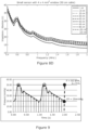
- Figure 7A is a proof-of-concept example showing how the absolute impedance of a piezoelectric sensor, (with an active area of 9x9 mm 2 ), varied with applied frequency in a range of 0.1 - 30 MHz.
- the external load pressure in this example was varied using a column of water with a height from 0 cm to 120cm (i.e. approximately 0-90 mmHg).
- the thickness mode has a resonant frequency around 18 MHz; and the transverse mode has a resonant frequency in the low MHz range.
- the pressure sampling rate may be fast, for example, 10 samples per second. This allows rapid monitoring of changes in instantaneous pressure. For example, this beneficially allows a user (or clinician) to monitor changes in compartment pressure during specific tests, such as when a limb is raised. Again as an example, the pressure in a muscular compartment may increase if a limb is raised. Further, this beneficially allows instantaneous pressure measurements to be monitored during activity. Pressure measurement during activity allows a clinical diagnosis of exertional compartment syndrome.
- the measured resonant frequency is processed to provide information regarding dynamic pressure changes.
- the calibrated baseline and/or the static compartment pressures may be removed from the measured response to provide dynamic pressure values. This allows pulse rates and amplitudes to be determined (with respect to the baseline value).
- the pressure sampling may be slow, for example, 1 sample per minute. This beneficially allows trends in static pressures to be monitored over an extended period of time.
- the pressure is monitored over a period of many hours.
- a slow sampling rate requires a lower power input, which also preserves battery life.
- Figure 7B is a magnified view of Figure 7A between a range of 16 and 22 MHz with a column height from 0 cm to 60 cm (i.e. approximately 0 - 45 mmHg). These frequencies correspond to the resonant frequency of the thickness mode. As the load pressure increases, the impedance of the sensor decreases systematically.
- Figure 7C is a magnified view of Figure 7A between a range of 16 and 22 MHz with a column height from 70 to 120 cm (i.e. approximately 50 - 90 mmHg). These frequencies correspond to the resonant frequency of the thickness mode. As the load pressure increases (above 50 mmHg), the impedance of the sensor was found to increase. Without wishing to be bound by any theory or conjecture, it is believed that this is due to the large size of the sensor, and a change in contact area and electrode connection due to deformation under these high pressures. These effects were not observed for sensors of a small size.
- Figure 8A is a proof-of-concept example showing how the absolute impedance of a piezoelectric sensor (with an active area of 4 ⁇ 4 mm 2 ) varied with applied frequency in a range of 0.1 - 30 MHz.
- the external load pressure in this example was varied using a column of water with a height from 0 cm to 120 cm (i.e. approximately 0 - 90 mmHg).
- the thickness mode has a resonant frequency around 18 MHz; and the transverse mode has a resonant frequency in the low MHz range.
- Figures 8B and 8C are magnified views of Figure 8A between a (high) frequency range of 16 and 22 MHz across the same pressure range. These frequencies correspond to the resonant frequency of the thickness mode. As the load pressure was increased, the absolute impedance of the sensor decreased systematically.
- Figure 8D is a magnified view of Figure 8A between a (low) frequency range of 0.4 and 2 MHz. These frequencies correspond to the resonant frequency of the transverse mode. At this lower frequency, the absolute impedance increased systematically as the load pressure increased.
- the results of the proof-of-concept experiments can be used to generate calibration curves for a device having the same sized active area.
- the device 10, 210 provides a dynamic pressure measurement.
- a dynamic pressure measurement is, for example, suitable for measuring delta pressure, arterial pulse rate, and for monitoring an attenuated and transformed cardiac cycle.
- the sensor is not electrically (or ultrasonically) stimulated.
- the piezoelectric sensor 22 will provide a measurable response, such as an electrical or ultrasound signal, in response to a change in the pressure differential.
- the electrical signal is measured as a change in impedance across the sensor 22.
- the passive operational mode there is no change in electrical signal if the pressure differential is a constant value. Therefore, the passive mode is not suitable for measuring static pressures.
- pulsatile pressure waves generated as a result of the cardiac cycle may be detected using the passive operational mode.
- the device is able to switch between the stimulated and passive modes.
- the processor correlates a change in the measured signal with a change in pressure differential between the exterior of the needle (P ext ) and the internal bore (P bore ).
- temporal data in the measured signal is used to determine the pulse rate.
- the pressure sampling rate is 10 samples / second. This sampling rate is sufficiently fast to accurately record pulse rates of approximately 60 bpm (beats per minute). Faster sampling rates could be employed to record the pulsatile pressure waves in greater resolution. In some exemplary methods, the sampling rate is at least 10 times as fast as the pulse rate.
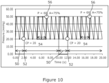
- Figure 9 shows the pressure variation in a muscular compartment during two arterial pressure waves at a pulse rate of 60 bpm (beats per minute). The pressure is sampled at a rate of 10 samples per second. The peak pressure can be analysed to determine the pulse rate.
- the mean arterial pressure (MAP) may be determined using known formulae.
- the delta pressure and the compartment pressure may be determined using known formulae.
- the first, second and/or third exemplary method may measure blood flow characteristics in terms of acoustic and pressure sensed signals which can be interpreted to yield information on the state of a blood vessel, for example, at the site of a cardiac procedure and in postoperative care to monitor internal blood pressure levels and conditions.
- the first, second, and/or third exemplary methods are alternated. That is, the electrical impedance (or resonant frequency) is measured alternately with measurements of changes in electrical impedance.
- Figure 10 shows the pressure variation in a muscular compartment at a pulse rate of 60 bpm (beats per minute).
- the pressure sensor is electrically stimulated during the period indicated by reference numeral 50.
- the electrical impedance (or resonant frequency) of the pressure sensor is measured at 52.
- the electrical impedance (or resonant frequency) is measured at a sampling rate of 6 samples per minute.
- the sample duration is 2 s. That is, the pressure sensor receives electrical stimulation during the electrical impedance (or resonant frequency) measurement for a duration of 2 s.
- the device is not electrically (or ultrasonically) stimulated during the period indicated by reference numeral 54. Whilst the pressure sensor is not being electrically (or ultrasonically) stimulated, the device can measure dynamic changes in pressure differential. Changes in electrical resistance of the pressure sensor are measured at 56. For example, changes in electrical impedance of the pressure sensor may be measured in accordance with the third exemplary method. This can provide clinical information such as pulse rate.
- the peak pressure can be analysed to determine the pulse rate.
- the mean arterial pressure (MAP) and the delta pressure may be determined using known formulae. Alternating between first, second and/or third exemplary methods reduces power consumption and helps to preserve battery life.
- the fourth exemplary method may measure blood flow characteristics in terms of acoustic and pressure sensed signals which can be interpreted to yield information on the state of a blood vessel, for example, at the site of a cardiac procedure and in postoperative care to monitor internal blood pressure levels and conditions.
- the device delays or suspends pressure measurements during needle insertion into a body.
- the device is switchable between the first, second, third, and/or fourth exemplary methods.
- the sampling rate is user adjustable.
- the tube comprises a flexible tube.
- the flexible tube may be hollow, comprising an internal bore, a closed first end (or tip) and an open second end, as described in relation to previous embodiments.
- the flexible tube may have any cross-sectional geometry.
- the flexible tube may comprise a pressure sensor as described in previous embodiments.
- the flexible tube (or needle) has a blunt end.
- the flexible tube may be positioned at a location in a body for pressure measurement during a surgical procedure or via a cannula, rather than being inserted into a body by penetrating body tissue.
- Embodiments incorporating a flexible tube have applications in, for example, measuring post-operative intracranial pressure; and monitoring arterial pressure at locations along a blood vessel to indicate arterial narrowing. Identifying arterial narrowing provides an indication that angioplasty or similar treatments may be required.
- the pressure sensor provides the closure for the closed first end.
- the pressure sensor comprises at least two pressure sensors.
- the pressure sensor may be a dual-segment hybrid sensor.
- the first pressure sensor is operated in the first and/or second exemplary method, and the second pressure sensor is operated in the third exemplary method.
- an insertion site guide is used to indicate the appropriate needle insertion site.
- the insertion site guide may comprise a wearable sleeve or sheet for position over the body.
- the insertion site guide may be made from a transparent, flexible material.
- the insertion site guide may comprise an indication of the location of muscular compartments. Correct positioning of the insertion site guide may be achieved using reference points provided on the insertion site guide.
- the insertion site guide may provide an indication of the necessary needle penetration depth for a muscular compartment.
- the insertion site guide beneficially facilitates insertion of the needle into the correct location and at the correct penetration depth to measure the pressure differential value of interest.
- the insertion site guide also beneficially facilitates insertion of the needle at the same location, which reduces experimental variation during repeated pressure measurements.
- Non-medical applications of the present invention include, but are not limited to, measuring a pressure differential: in a pressurised chamber, such as a tyre; in a sealed chamber, such as a sealed reaction vessel; or in a low pressure chamber, such as a vacuum chamber.
Landscapes
- Health & Medical Sciences (AREA)
- Life Sciences & Earth Sciences (AREA)
- Physics & Mathematics (AREA)
- Surgery (AREA)
- General Health & Medical Sciences (AREA)
- Engineering & Computer Science (AREA)
- Biomedical Technology (AREA)
- Heart & Thoracic Surgery (AREA)
- Medical Informatics (AREA)
- Molecular Biology (AREA)
- Biophysics (AREA)
- Animal Behavior & Ethology (AREA)
- Pathology (AREA)
- Public Health (AREA)
- Veterinary Medicine (AREA)
- Hematology (AREA)
- Cardiology (AREA)
- General Physics & Mathematics (AREA)
- Vascular Medicine (AREA)
- Physiology (AREA)
- Measuring And Recording Apparatus For Diagnosis (AREA)
- Measuring Fluid Pressure (AREA)
Claims (15)
- Vorrichtung (10) zum Messen einer Druckdifferenz, umfassend:ein Rohr (12) umfassend einen geschlossenen Einführabschnitt zum Einführen in einen Körper, wobei der Einführabschnitt ein Einführende (18) und eine Innenbohrung (16) aufweist, die über eine Öffnung (20) in dem Rohr mit dem Umgebungsdruck in Verbindung steht;mindestens einen Drucksensor (22), der sich in oder auf dem Einführabschnitt befindet, wobei der Drucksensor einen nach innen gerichteten Bereich (24b), der mit der Innenbohrung in Verbindung steht, und einen nach außen gerichteten Bereich (24a), der mit einer Außenseite des Rohrs in Verbindung steht, umfasst; undeinen Prozessor, der so konfiguriert ist, dass er einen Stimulus bereitstellt, um den Drucksensor mechanisch zu erregen, so dass der Drucksensor bei Bereitstellung des Stimulus eine messbare Resonanzantwort liefert, wobei der Prozessor die messbare Resonanzantwort mit dem Druckunterschied zwischen der Außenseite des Rohrs und der Innenbohrung korreliert.
- Vorrichtung nach Anspruch 1, wobei sich der mindestens eine Drucksensor proximal zu dem Einführende befindet.
- Vorrichtung nach Anspruch 1 oder Anspruch 2, umfassend eine Vielzahl von Drucksensoren, wobei optional mindestens zwei der Drucksensoren bei gleichem Druckunterschied unterschiedliche Resonanzfrequenzen aufweisen.
- Vorrichtung nach einem der vorstehenden Ansprüche, wobei der mindestens eine Drucksensor ein elektromechanisches oder mikroelektromechanisches (MEMs) Material umfasst.
- Vorrichtung nach einem der vorstehenden Ansprüche, wobei der mindestens eine Drucksensor einen piezoelektrischen Drucksensor oder einen elektrokapazitiven Drucksensor umfasst.
- Vorrichtung nach einem der vorstehenden Ansprüche, wobei der Stimulus einen elektrischen Stimulus umfasst.
- Vorrichtung nach einem der vorstehenden Ansprüche, wobei die messbare Resonanzantwort eine elektrische Antwort ist.
- Vorrichtung nach einem der vorstehenden Ansprüche, bei der die messbare Resonanzantwort eine elektrische Impedanz des Drucksensors angibt und/oder die messbare Resonanzantwort eine Resonanzfrequenz des Drucksensors angibt.
- Vorrichtung nach einem der vorstehenden Ansprüche, wobei die messbare Resonanzantwort eine Änderung der Druckdifferenz zwischen der Außenseite des Rohrs und der Innenbohrung angibt.
- Vorrichtung nach einem der vorstehenden Ansprüche, ferner umfassend einen vom Benutzer haltbaren Abschnitt (14), der mit dem Rohr in Verbindung steht, wobei der vom Benutzer haltbare Abschnitt optional mit dem Nicht-Einführabschnitt in Verbindung steht und wobei ferner optional die Innenbohrung über den vom Benutzer haltbaren Abschnitt mit dem Umgebungsdruck in Verbindung steht.
- Vorrichtung nach Anspruch 10, wobei der vom Benutzer haltbare Abschnitt einen Penetrationsbegrenzungsmechanismus (236, 238, 242, 244) umfasst, der betätigbar ist, um die Penetrationstiefe des Rohres zu begrenzen, und wobei der Penetrationsbegrenzungsmechanismus optional ein Verriegelungsmittel (246) umfasst.
- Vorrichtung nach einem der vorstehenden Ansprüche, wobei das Rohr eine Nadel ist.
- Verfahren zum Messen eines Druckunterschieds unter Verwendung der Vorrichtung nach Anspruch 1, wobei das Verfahren die folgenden Schritte umfasst:Bereitstellen eines Stimulus zum mechanischen Erregen des Drucksensors, so dass der Drucksensor eine messbare Resonanzantwort bereitstellt;Messen der messbaren Resonanzantwort, wobei die messbare Resonanzantwort den Druckunterschied zwischen der Außenseite des Rohrs und der Innenbohrung angibt, wobei die Innenbohrung über die Öffnung in dem Rohr mit dem Umgebungsdruck in Verbindung steht; undKorrelieren der messbaren Resonanzantwort mit dem Druckunterschied zwischen der Außenseite des Rohrs und der Innenbohrung.
- Verfahren nach Anspruch 13, ferner umfassend den Schritt des Kalibrierens der Vorrichtung, wobei der Schritt des Kalibrierens der Vorrichtung die folgenden Unterschritte umfasst:Bereitstellen eines Stimulus zum mechanischen Erregen des Drucksensors, während der nach außen gerichtete Bereich des Drucksensors auf Umgebungsdruck gehalten wird, so dass der Drucksensor eine messbare Resonanzkalibrierungsantwort liefert, die den Druckunterschied zwischen der Außenseite des Rohrs und der Innenbohrung angibt;Messen der messbaren Resonanzkalibrierungsantwort; undKorrelieren der gemessenen Resonanzkalibrierungsantwort mit einem Druckunterschied von Null;mit der Maßgabe, dass der Einführabschnitt der Vorrichtung während des Schritts des Messens der messbaren Resonanzantwort nicht in einen menschlichen oder tierischen Körper eingeführt wird.
- Verfahren nach Anspruch 13 oder 14, wobei der Stimulus ein alternierender und/oder gepulster elektrischer Stimulus ist und/oder die Frequenz des Stimulus variiert wird, wobei optional die Frequenz des Stimulus von einer ersten Frequenz auf eine zweite Frequenz erhöht oder verringert wird.
Applications Claiming Priority (2)
| Application Number | Priority Date | Filing Date | Title |
|---|---|---|---|
| GB2006020.8A GB2601284B (en) | 2020-04-24 | 2020-04-24 | Device for measuring a pressure differential |
| PCT/GB2021/050995 WO2021214489A1 (en) | 2020-04-24 | 2021-04-23 | Device for measuring a pressure differential |
Publications (3)
| Publication Number | Publication Date |
|---|---|
| EP4138650A1 EP4138650A1 (de) | 2023-03-01 |
| EP4138650B1 true EP4138650B1 (de) | 2024-12-18 |
| EP4138650C0 EP4138650C0 (de) | 2024-12-18 |
Family
ID=71080135
Family Applications (1)
| Application Number | Title | Priority Date | Filing Date |
|---|---|---|---|
| EP21724354.2A Active EP4138650B1 (de) | 2020-04-24 | 2021-04-23 | Vorrichtung und verfahren zur messung einer druckdifferenz |
Country Status (5)
| Country | Link |
|---|---|
| US (1) | US20230181054A1 (de) |
| EP (1) | EP4138650B1 (de) |
| ES (1) | ES3014876T3 (de) |
| GB (1) | GB2601284B (de) |
| WO (1) | WO2021214489A1 (de) |
Families Citing this family (1)
| Publication number | Priority date | Publication date | Assignee | Title |
|---|---|---|---|---|
| CN112099661B (zh) * | 2020-08-17 | 2024-05-03 | 深圳市优必选科技股份有限公司 | 一种压力检测方法、装置及电子设备 |
Family Cites Families (9)
| Publication number | Priority date | Publication date | Assignee | Title |
|---|---|---|---|---|
| US3553625A (en) * | 1967-12-29 | 1971-01-05 | Statham Instrument Inc | Side sensitive miniaturized pressure transducer |
| US3703099A (en) * | 1969-11-12 | 1972-11-21 | Ici Ltd | Pressure transducer |
| US4817629A (en) | 1986-01-03 | 1989-04-04 | Stryker Corporation | Process and apparatus for measurement and monitoring of muscle compartment pressure |
| US4886070A (en) * | 1988-05-11 | 1989-12-12 | Thermometrics, Inc. | Method of in vivo calibration of a pressure sensor |
| US6115624A (en) * | 1997-07-30 | 2000-09-05 | Genesis Technologies, Inc. | Multiparameter fetal monitoring device |
| US20060116602A1 (en) * | 2004-12-01 | 2006-06-01 | Alden Dana A | Medical sensing device and system |
| US20140288459A1 (en) * | 2013-03-25 | 2014-09-25 | Cardiomems, Inc. | Ventricular shunt system and method |
| CN206197935U (zh) * | 2016-07-28 | 2017-05-31 | 四川经纬灵仪科技有限公司 | 用于颅内压力监测的传感器 |
| US20180168460A1 (en) * | 2016-12-20 | 2018-06-21 | Medtronic, Inc. | Measuring cardiovascular pressure based on patient state |
-
2020
- 2020-04-24 GB GB2006020.8A patent/GB2601284B/en active Active
-
2021
- 2021-04-23 WO PCT/GB2021/050995 patent/WO2021214489A1/en not_active Ceased
- 2021-04-23 ES ES21724354T patent/ES3014876T3/es active Active
- 2021-04-23 US US17/920,905 patent/US20230181054A1/en active Pending
- 2021-04-23 EP EP21724354.2A patent/EP4138650B1/de active Active
Also Published As
| Publication number | Publication date |
|---|---|
| GB2601284A (en) | 2022-06-01 |
| WO2021214489A1 (en) | 2021-10-28 |
| ES3014876T3 (en) | 2025-04-25 |
| EP4138650A1 (de) | 2023-03-01 |
| EP4138650C0 (de) | 2024-12-18 |
| GB2601284B (en) | 2024-04-24 |
| GB202006020D0 (en) | 2020-06-10 |
| US20230181054A1 (en) | 2023-06-15 |
Similar Documents
| Publication | Publication Date | Title |
|---|---|---|
| US9301711B2 (en) | System and method for assessing neural health | |
| US20200268953A1 (en) | Medical product comprising a functional element for the invasive use in a patient's body | |
| US8372009B2 (en) | System and method for treating a therapeutic site | |
| US6773407B2 (en) | Non-invasive method of determining absolute intracranial pressure | |
| WO2001054584A1 (en) | Ultrasonic apparatus and technique to measure changes in intracranial pressure | |
| US6740048B2 (en) | Non-invasive method of determining diastolic intracranial pressure | |
| EP1985229A2 (de) | System für Drainage des Liquors aus einer Flüssigkeitshöhle des Gehirns- oder Rückenmarks | |
| EP3352675B1 (de) | Vorrichtung zur erkennung von erhöhter hirnschwellung und/oder -verlagerung | |
| US8764677B2 (en) | Implantable surface acoustic wave devices for long term clinical monitoring | |
| WO1999005963A1 (en) | Multiparameter fetal monitoring device | |
| EP2648608A2 (de) | Implantierbarer drucksensor | |
| CA2847374A1 (en) | Method of detecting portal and/or hepatic pressure and a portal hypertension monitoring system | |
| US3720201A (en) | Disposable body fluid pressure monitor | |
| US4036216A (en) | Body fluid pressure system | |
| EP2898824A1 (de) | Blutdruckmesssystem | |
| EP4138650B1 (de) | Vorrichtung und verfahren zur messung einer druckdifferenz | |
| JP2009153843A (ja) | 血圧測定装置 | |
| US20090221894A1 (en) | Minimally invasive vessel location | |
| US20090275845A1 (en) | Method and device for the non-invasive detection of blood flow and associated parameters in particular arterial waveform and blood pressure | |
| JPS5816888B2 (ja) | ツカイステケツアツモニタソウチ | |
| He et al. | Dual-stiffness force-sensing cannulation tool for retinal microsurgery | |
| Rader et al. | An implantable blood pressure and flow transmitter | |
| WO2009132396A1 (en) | Method and apparatus for determining the pressure of a fluid | |
| US20250268559A1 (en) | Non-invasive resonant detection of pressure | |
| RU99101828A (ru) | Способ и устройство для неинвазивного выявления медицинских состояний за счет текущего контроля периферического артериального тонуса |
Legal Events
| Date | Code | Title | Description |
|---|---|---|---|
| STAA | Information on the status of an ep patent application or granted ep patent |
Free format text: STATUS: UNKNOWN |
|
| STAA | Information on the status of an ep patent application or granted ep patent |
Free format text: STATUS: THE INTERNATIONAL PUBLICATION HAS BEEN MADE |
|
| PUAI | Public reference made under article 153(3) epc to a published international application that has entered the european phase |
Free format text: ORIGINAL CODE: 0009012 |
|
| STAA | Information on the status of an ep patent application or granted ep patent |
Free format text: STATUS: REQUEST FOR EXAMINATION WAS MADE |
|
| 17P | Request for examination filed |
Effective date: 20221124 |
|
| AK | Designated contracting states |
Kind code of ref document: A1 Designated state(s): AL AT BE BG CH CY CZ DE DK EE ES FI FR GB GR HR HU IE IS IT LI LT LU LV MC MK MT NL NO PL PT RO RS SE SI SK SM TR |
|
| DAV | Request for validation of the european patent (deleted) | ||
| DAX | Request for extension of the european patent (deleted) | ||
| STAA | Information on the status of an ep patent application or granted ep patent |
Free format text: STATUS: EXAMINATION IS IN PROGRESS |
|
| 17Q | First examination report despatched |
Effective date: 20231103 |
|
| GRAP | Despatch of communication of intention to grant a patent |
Free format text: ORIGINAL CODE: EPIDOSNIGR1 |
|
| STAA | Information on the status of an ep patent application or granted ep patent |
Free format text: STATUS: GRANT OF PATENT IS INTENDED |
|
| INTG | Intention to grant announced |
Effective date: 20240708 |
|
| GRAS | Grant fee paid |
Free format text: ORIGINAL CODE: EPIDOSNIGR3 |
|
| GRAA | (expected) grant |
Free format text: ORIGINAL CODE: 0009210 |
|
| STAA | Information on the status of an ep patent application or granted ep patent |
Free format text: STATUS: THE PATENT HAS BEEN GRANTED |
|
| AK | Designated contracting states |
Kind code of ref document: B1 Designated state(s): AL AT BE BG CH CY CZ DE DK EE ES FI FR GR HR HU IE IS IT LI LT LU LV MC MK MT NL NO PL PT RO RS SE SI SK SM TR |
|
| RBV | Designated contracting states (corrected) |
Designated state(s): AL AT BE BG CH CY CZ DE DK EE ES FI FR GR HR HU IE IS IT LI LT LU LV MC MK MT NL NO PL PT RO RS SE SI SK SM TR |
|
| REG | Reference to a national code |
Ref country code: CH Ref legal event code: EP |
|
| REG | Reference to a national code |
Ref country code: DE Ref legal event code: R096 Ref document number: 602021023568 Country of ref document: DE |
|
| REG | Reference to a national code |
Ref country code: IE Ref legal event code: FG4D |
|
| U01 | Request for unitary effect filed |
Effective date: 20250103 |
|
| U07 | Unitary effect registered |
Designated state(s): AT BE BG DE DK EE FI FR IT LT LU LV MT NL PT RO SE SI Effective date: 20250115 |
|
| PG25 | Lapsed in a contracting state [announced via postgrant information from national office to epo] |
Ref country code: HR Free format text: LAPSE BECAUSE OF FAILURE TO SUBMIT A TRANSLATION OF THE DESCRIPTION OR TO PAY THE FEE WITHIN THE PRESCRIBED TIME-LIMIT Effective date: 20241218 |
|
| PG25 | Lapsed in a contracting state [announced via postgrant information from national office to epo] |
Ref country code: NO Free format text: LAPSE BECAUSE OF FAILURE TO SUBMIT A TRANSLATION OF THE DESCRIPTION OR TO PAY THE FEE WITHIN THE PRESCRIBED TIME-LIMIT Effective date: 20250318 |
|
| PG25 | Lapsed in a contracting state [announced via postgrant information from national office to epo] |
Ref country code: GR Free format text: LAPSE BECAUSE OF FAILURE TO SUBMIT A TRANSLATION OF THE DESCRIPTION OR TO PAY THE FEE WITHIN THE PRESCRIBED TIME-LIMIT Effective date: 20250319 |
|
| REG | Reference to a national code |
Ref country code: ES Ref legal event code: FG2A Ref document number: 3014876 Country of ref document: ES Kind code of ref document: T3 Effective date: 20250425 |
|
| PG25 | Lapsed in a contracting state [announced via postgrant information from national office to epo] |
Ref country code: RS Free format text: LAPSE BECAUSE OF FAILURE TO SUBMIT A TRANSLATION OF THE DESCRIPTION OR TO PAY THE FEE WITHIN THE PRESCRIBED TIME-LIMIT Effective date: 20250318 |
|
| U20 | Renewal fee for the european patent with unitary effect paid |
Year of fee payment: 5 Effective date: 20250424 |
|
| PG25 | Lapsed in a contracting state [announced via postgrant information from national office to epo] |
Ref country code: SM Free format text: LAPSE BECAUSE OF FAILURE TO SUBMIT A TRANSLATION OF THE DESCRIPTION OR TO PAY THE FEE WITHIN THE PRESCRIBED TIME-LIMIT Effective date: 20241218 |
|
| PG25 | Lapsed in a contracting state [announced via postgrant information from national office to epo] |
Ref country code: PL Free format text: LAPSE BECAUSE OF FAILURE TO SUBMIT A TRANSLATION OF THE DESCRIPTION OR TO PAY THE FEE WITHIN THE PRESCRIBED TIME-LIMIT Effective date: 20241218 |
|
| PGFP | Annual fee paid to national office [announced via postgrant information from national office to epo] |
Ref country code: ES Payment date: 20250505 Year of fee payment: 5 |
|
| PG25 | Lapsed in a contracting state [announced via postgrant information from national office to epo] |
Ref country code: IS Free format text: LAPSE BECAUSE OF FAILURE TO SUBMIT A TRANSLATION OF THE DESCRIPTION OR TO PAY THE FEE WITHIN THE PRESCRIBED TIME-LIMIT Effective date: 20250418 |
|
| PG25 | Lapsed in a contracting state [announced via postgrant information from national office to epo] |
Ref country code: SK Free format text: LAPSE BECAUSE OF FAILURE TO SUBMIT A TRANSLATION OF THE DESCRIPTION OR TO PAY THE FEE WITHIN THE PRESCRIBED TIME-LIMIT Effective date: 20241218 |
|
| PG25 | Lapsed in a contracting state [announced via postgrant information from national office to epo] |
Ref country code: CZ Free format text: LAPSE BECAUSE OF FAILURE TO SUBMIT A TRANSLATION OF THE DESCRIPTION OR TO PAY THE FEE WITHIN THE PRESCRIBED TIME-LIMIT Effective date: 20241218 |
|
| PLBE | No opposition filed within time limit |
Free format text: ORIGINAL CODE: 0009261 |
|
| STAA | Information on the status of an ep patent application or granted ep patent |
Free format text: STATUS: NO OPPOSITION FILED WITHIN TIME LIMIT |
|
| REG | Reference to a national code |
Ref country code: CH Ref legal event code: L10 Free format text: ST27 STATUS EVENT CODE: U-0-0-L10-L00 (AS PROVIDED BY THE NATIONAL OFFICE) Effective date: 20251029 |
|
| REG | Reference to a national code |
Ref country code: CH Ref legal event code: H13 Free format text: ST27 STATUS EVENT CODE: U-0-0-H10-H13 (AS PROVIDED BY THE NATIONAL OFFICE) Effective date: 20251125 |
|
| 26N | No opposition filed |
Effective date: 20250919 |