EP4138370A1 - Terminal device - Google Patents
Terminal device Download PDFInfo
- Publication number
- EP4138370A1 EP4138370A1 EP22753578.8A EP22753578A EP4138370A1 EP 4138370 A1 EP4138370 A1 EP 4138370A1 EP 22753578 A EP22753578 A EP 22753578A EP 4138370 A1 EP4138370 A1 EP 4138370A1
- Authority
- EP
- European Patent Office
- Prior art keywords
- groove
- middle frame
- terminal device
- outlet holes
- sealing member
- Prior art date
- Legal status (The legal status is an assumption and is not a legal conclusion. Google has not performed a legal analysis and makes no representation as to the accuracy of the status listed.)
- Pending
Links
- 238000007789 sealing Methods 0.000 claims abstract description 112
- 238000004891 communication Methods 0.000 claims abstract description 29
- 230000007704 transition Effects 0.000 claims description 7
- 238000004519 manufacturing process Methods 0.000 abstract description 6
- 238000010586 diagram Methods 0.000 description 6
- 239000006260 foam Substances 0.000 description 2
- 239000003292 glue Substances 0.000 description 2
- 229920002799 BoPET Polymers 0.000 description 1
- 239000005041 Mylar™ Substances 0.000 description 1
- 230000005540 biological transmission Effects 0.000 description 1
- 230000000694 effects Effects 0.000 description 1
- 238000005516 engineering process Methods 0.000 description 1
- 238000012986 modification Methods 0.000 description 1
- 230000004048 modification Effects 0.000 description 1
Images


Classifications
-
- H—ELECTRICITY
- H05—ELECTRIC TECHNIQUES NOT OTHERWISE PROVIDED FOR
- H05K—PRINTED CIRCUITS; CASINGS OR CONSTRUCTIONAL DETAILS OF ELECTRIC APPARATUS; MANUFACTURE OF ASSEMBLAGES OF ELECTRICAL COMPONENTS
- H05K5/00—Casings, cabinets or drawers for electric apparatus
- H05K5/02—Details
- H05K5/0217—Mechanical details of casings
-
- H—ELECTRICITY
- H04—ELECTRIC COMMUNICATION TECHNIQUE
- H04M—TELEPHONIC COMMUNICATION
- H04M1/00—Substation equipment, e.g. for use by subscribers
- H04M1/02—Constructional features of telephone sets
- H04M1/03—Constructional features of telephone transmitters or receivers, e.g. telephone hand-sets
- H04M1/035—Improving the acoustic characteristics by means of constructional features of the housing, e.g. ribs, walls, resonating chambers or cavities
-
- H—ELECTRICITY
- H05—ELECTRIC TECHNIQUES NOT OTHERWISE PROVIDED FOR
- H05K—PRINTED CIRCUITS; CASINGS OR CONSTRUCTIONAL DETAILS OF ELECTRIC APPARATUS; MANUFACTURE OF ASSEMBLAGES OF ELECTRICAL COMPONENTS
- H05K5/00—Casings, cabinets or drawers for electric apparatus
- H05K5/02—Details
- H05K5/03—Covers
Definitions
- Embodiments of this application relate to the field of terminal technologies, and in particular, to a terminal device.
- Terminal devices developing toward an ultimate screen-to-body ratio.
- holes are arranged on the top of a middle frame, to form sound outlet holes of a receiver, and the positions of the sound outlet holes of the receiver are changed from the front of the screen to the top of the terminal device, thereby reducing black borders of the screen and obtaining a greater screen ratio.
- a front sound cavity of the receiver of the terminal device needs to be sealed, to ensure that a sound from the receiver is emitted only from the sound outlet holes.
- the receiver is sealedly connected to a support by a sealing member, the support is sealedly connected to the middle frame by another sealing member, a through hole corresponding to the receiver is arranged on the support, and a groove is arranged on a side of the support facing away from the receiver, and the groove is in communication with the through hole and the sound outlet holes respectively, thereby forming the sealed front sound cavity of the receiver.
- the receiver is mounted on the middle frame with the help of the support, and the groove and the through hole for forming the structure of the front sound cavity are arranged on the support, resulting in high manufacturing and mounting costs of the support.
- this application provides a low-cost terminal device in which a structure of a front sound cavity of a receiver is formed.
- the terminal device includes a middle frame, a receiver assembly, and a sealing assembly.
- the middle frame includes a first surface and a second surface. The first surface and the second surface are arranged opposite to each other. Sound outlet holes are arranged on the middle frame.
- a first groove is arranged on the first surface of the middle frame. The first groove is in communication with the sound outlet holes.
- a first through hole is arranged on a bottom wall of the first groove.
- the receiver assembly is arranged on the second surface of the middle frame.
- the receiver assembly is sealedly connected to the middle frame, and corresponds to the first through hole.
- the sealing assembly is configured to seal the first groove.
- the first groove of the middle frame and the first through hole form a front sound cavity of the receiver assembly.
- the middle frame is sealedly connected to the receiver assembly, and the sealing assembly seals the first groove, so that the front sound cavity of the receiver assembly is sealed, and a sound from the receiver assembly is emitted only from the sound outlet holes on the middle frame.
- the cost of the sealing assembly for sealing the structure of the front sound cavity is low, and the cost of manufacturing the first groove and the first through hole on the middle frame is low.
- the receiver assembly includes a receiver and a first sealing member.
- a second through hole is arranged on the first sealing member.
- the second through hole is in communication with the first through hole.
- a second groove is arranged on the second surface.
- the receiver is arranged in the second groove, and is sealedly connected to a bottom wall of the second groove by the first sealing member.
- the second groove provides a mounting space for the receiver assembly, and the second through hole communicates the receiver assembly with the first groove and the sound outlet holes.
- the sealing assembly includes a cover plate and a second sealing member.
- the cover plate is arranged in the first groove.
- the second sealing member is adhered to the middle frame.
- the second sealing member covers a gap between the cover plate and the middle frame.
- the cover plate is arranged in the first groove, and a cavity is formed between the cover plate and the bottom wall of the first groove, and the cavity and the first through hole form the front sound cavity of the receiver assembly.
- the second sealing member covers the gap between the cover plate and the middle frame, so that the front sound cavity is sealed.
- a protruding mounting portion is arranged in the first groove.
- the sealing assembly further includes a third sealing member.
- the third sealing member is arranged on the mounting portion.
- the cover plate is arranged on a side of the third sealing member facing away from the mounting portion.
- the cover plate is fixed in the first groove by the third sealing member, so that the cover plate and the middle frame are preliminarily sealed.
- the middle frame further includes a side frame.
- the side frame surrounds outer sides of the first surface and the second surface, and is connected to the first surface and the second surface respectively.
- the sound outlet holes are arranged on the side frame.
- the first groove includes a first groove portion and a second groove portion that are in communication.
- the first through hole is in communication with the first groove portion.
- the second groove portion is located on a junction of the first surface and the side frame, and is in communication with the sound outlet holes.
- the first groove portion is in communication with the first through hole, and the second groove portion is in communication with the sound outlet holes, so that a sound emitted by the receiver assembly is transmitted through the sound outlet holes.
- the second groove portion provides a demolding space for the sound outlet holes, and does not occupy the mounting space on the second surface.
- the first surface and the side frame are connected by a rounded transition surface.
- the cover plate includes an engagement portion with an arc-shaped structure.
- the engagement portion is arranged in the second groove portion, so that the engagement portion and a surface of the middle frame coincide on the junction of the side frame and the first surface.
- the engagement portion with the arc-shaped structure adapts to the manner in which the first surface is connected to the rounded transition surface of the side frame, and the engagement portion and the middle frame coincide on the junction of the side frame and the first surface, so that the second sealing member easily covers the gap between the cover plate and the middle frame.
- the cover plate includes a body and an engagement portion.
- the body is arranged in the first groove portion, and the engagement portion is arranged in the second groove portion, so that the bottom wall of the first groove and the sound outlet holes are located on a same side of the cover plate.
- the first groove and the sound outlet holes are located on the same side of the cover plate, and the body and the engagement portion communicate the first groove with the sound outlet holes, so that the front sound cavity of the receiver assembly is formed between the cover plate and the bottom wall of the first groove, and the front sound cavity of the receiver assembly is preliminarily enclosed.
- arc-shaped grooves are arranged on the engagement portion.
- the arc-shaped grooves are butted with the sound outlet holes.
- the arc-shaped grooves ensure that the engagement portion does not block the sound outlet holes, thereby ensuring the sound quality.
- protruding support portions are arranged on a side of the engagement portion toward the bottom wall of the first groove.
- the support portions are in contact with a groove wall of the second groove portion.
- the support portions are in contact with the groove wall of the second groove portion, which improves the strength of the engagement portion, so that the engagement portion is not easily deformed by collision, and is not easy to block the sound outlet holes.
- a third groove is arranged on the bottom wall of the first groove.
- the third groove increases the space size of the front sound cavity of the receiver assembly, thereby ensuring the sound quality.
- Terminal device 100; middle frame: 10; first surface: 101; second surface: 103; side frame: 105; rounded transition surface: 107; sound outlet hole: 11; first groove: 12; first groove portion: 1201; second groove portion: 1203; bottom wall: 121; mounting portion: 125; third groove: 127; first through hole: 14; second groove: 15; bottom wall: 151; receiver assembly: 20; receiver: 21; first sealing member: 23; second through hole: 231; sealing assembly: 30; cover plate: 33; body: 331; engagement portion: 333; arc-shaped groove: 3331; support portion: 3333; second sealing member: 35; and third sealing member: 37.
- the embodiments of this application provide a terminal device.
- the terminal device includes a middle frame, a receiver assembly, and a sealing assembly.
- the middle frame includes a first surface and a second surface that are arranged opposite to each other. Sound outlet holes are arranged on the middle frame.
- a first groove is arranged on the first surface of the middle frame. The first groove is in communication with the sound outlet holes.
- a first through hole is arranged on a bottom wall of the first groove.
- the receiver assembly is arranged on the second surface of the middle frame.
- the receiver assembly is sealedly connected to the middle frame, and corresponds to the first through hole.
- the sealing assembly is configured to seal the first groove.
- the first groove of the middle frame and the first through hole form a front sound cavity of the receiver assembly.
- the middle frame is sealedly connected to the receiver assembly, and the sealing assembly seals the first groove, so that the front sound cavity of the receiver assembly is sealed, and a sound from the receiver assembly is emitted only from the sound outlet holes on the middle frame.
- the cost of the sealing assembly for sealing the structure of the front sound cavity is low, and the cost of manufacturing the first groove and the first through hole on the middle frame is low.
- the terminal device 100 is a mobile phone, but is not limited thereto.
- the terminal device 100 includes a middle frame 10, a receiver assembly 20, and a sealing assembly 30.
- the receiver assembly 20 and the sealing assembly 30 are arranged on two opposite sides of the middle frame 10 respectively.
- the middle frame 10 includes a first surface 101 and a second surface 103.
- the first surface 101 and the second surface 103 are arranged opposite to each other.
- sound outlet holes 11 are arranged on the middle frame 10.
- the receiver assembly 20 is arranged on the second surface 103 of the middle frame 10, and is sealedly connected to the middle frame 10.
- a first groove 12 is arranged on the first surface 101 of the middle frame 10.
- the sealing assembly 30 is configured to seal the first groove 12.
- the first groove 12 is in communication with the sound outlet holes 11.
- a first through hole 14 is arranged on a bottom wall 121 of the first groove 12, and the first through hole 14 corresponds to the receiver assembly 20.
- the first groove 12 of the middle frame 10 and the first through hole 14 form a front sound cavity of the receiver assembly 20.
- the middle frame 10 is sealedly connected to the receiver assembly 20, and the sealing assembly 30 seals the first groove 12, so that the front sound cavity of the receiver assembly 20 is sealed, and a sound from the receiver assembly 20 is emitted only from the sound outlet holes 11 on the middle frame 10.
- the cost of the sealing assembly 30 for sealing the structure of the front sound cavity is low, and the cost of manufacturing the first groove 12 and the first through hole 14 that form the front sound cavity on the middle frame 10 is low.
- the first surface 101 and the second surface 103 may be a flat surface, a curved surface, or a stepped surface, or a surface formed by combining the above different surfaces.
- the first surface 101 of the middle frame 10 is for mounting the sealing assembly 30, and is further for mounting a screen (not shown in the figures) of the terminal device 100.
- the second surface 103 is for mounting the receiver assembly 20, and is further for mounting other structural members of the terminal device 100.
- the other structural members may be a camera and a circuit board (not shown in the figures).
- the receiver assembly 20 is electrically connected to the circuit board.
- a support is arranged on the second surface 103 of the middle frame 10, and groove structures forming a front sound cavity of a receiver are arranged on the support. Due to acoustic requirements, the space size of the front sound cavity of the receiver needs to reach a set value, to ensure stable sound transmission. A space for the front sound cavity to reach the set value needs to be provided on the support, resulting in an increased size of the support. Moreover, a demolding space for the sound outlet holes needs to be provided on a side of the support toward the middle frame 10, which further increases the size of the support. The support occupies a large mounting space on the middle frame 10, which may cause difficulty in the mounting and layout of the structural members of the terminal device on the second surface 103 of the middle frame 10.
- the receiver assembly 20 and the sealing assembly 30 are arranged on the two opposite sides of the middle frame 10, and the receiver assembly 20 occupies a small space on the second surface 103 of the middle frame 10.
- the first groove 12 is arranged on the first surface 101, and the sealing assembly 30 is arranged in the first groove 12.
- the sealing assembly 30 occupies no space on the first surface 101.
- the sealing assembly 30 occupies a small space on the first surface 101.
- the first groove 12 arranged on the first surface 101 is in communication with the sound outlet holes 11, which provides a demolding space for the sound outlet holes 11 and occupies no mounting space on the second surface 103 of the middle frame 10. In this way, the mounting space of the middle frame 10 is improved, so that the middle frame 10 can meet more stacking requirements, for example, can meet stacking mounting requirements of a camera assembly.
- a second groove 15 is arranged on the second surface 103 of the middle frame 10.
- the receiver assembly 20 is arranged in the second groove 15.
- the second groove 15 is in communication with the first groove 12 through the first through hole 14.
- the receiver assembly 20 includes a receiver 21 and a first sealing member 23.
- a second through hole 231 is arranged on the first sealing member 23.
- the first sealing member 23 is adhered to a bottom wall 151 of the second groove 15.
- the receiver 21 is arranged on the first sealing member 23.
- the receiver 21 is sealedly connected to the middle frame 10 by the first sealing member 23, and is in communication with the first through hole 14 through the second through hole 23.
- a sound emitted by the receiver 21 is transmitted from the sound outlet holes 11 after passing through the second through hole 231, the second groove 15, the first through hole 14, and the first groove 12.
- a side frame 105 is arranged on the middle frame 10.
- the side frame 105 is an annular wall structure surrounding outer sides of the first surface 101 and the second surface 103.
- the side frame 105 is connected to the first surface 101 and the second surface 103.
- the sound outlet holes 11 are arranged on the side frame 105.
- the sound outlet holes 11 penetrate through the side frame 105, and are in communication with the first groove 12.
- the sound outlet hole 11 is a circular hole, and there are a plurality of sound outlet holes 11. As shown in FIG. 4 , a plurality of sound outlet holes 11 are arranged on the side frame 105 at intervals.
- the sound outlet hole 11 may alternatively be a rectangular long hole or of another structure.
- the quantity and shape of the sound outlet holes 11 may be set according requirements, as long as the sound outlet holes 11 are in communication with the first groove 12 to transmit the sound emitted by the receiver 21.
- the sealing assembly 30 includes a cover plate 33 and a second sealing member 35.
- the cover plate 33 is arranged in the first groove 12. Specifically, a protruding mounting portion 125 is arranged on the bottom wall 121 of the first groove 12. The mounting portion 125 is located in the first groove 12, and does not protrude from the first surface 101.
- the cover plate 33 is arranged on the mounting portion 125.
- the second sealing member 35 is arranged on a side of the cover plate 33 facing away from the mounting portion 125, and is adhered to the middle frame 10. The second sealing member 35 covers a gap between the cover plate 33 and the middle frame 10 (specifically, a side wall of the first groove 12), so that the sealing assembly 30 is sealedly connected to the middle frame 10.
- the cover plate 33 is arranged on the mounting portion 125, so that a cavity is formed between the cover plate 33 and the bottom wall 121 of the first groove 12.
- the cavity is in communication with the first through hole 14 and the sound outlet holes 11 respectively, thereby forming a front sound cavity of the receiver 21.
- the first groove 12 includes a first groove portion 1201 and a second groove portion 1203 that are in communication.
- the first groove portion 1201 is arranged on the first surface 101.
- the mounting portion 125 is arranged in the first groove portion 1201.
- the first through hole 14 is in communication with the first groove portion 1201.
- the second groove portion 1203 is located on a side of the first groove portion 1201 toward the side frame 105, and is located on a junction of the first surface 101 and the side frame 105, so that the second groove portion 1203 is in communication with the plurality of sound outlet holes 11.
- the second groove portion 1203 is partially in communication with the first groove portion 1201, and extends toward a side of the first groove portion 1201, so that the first groove 12 is roughly L-shaped.
- the cover plate 33 includes a body 331 and an engagement portion 333.
- the body 331 is arranged on the mounting portion 125.
- the engagement portion 333 is arranged on a side of the body 331.
- the body 331 is arranged in the first groove portion 1201, and the engagement portion 333 is arranged in the second groove portion 1203, so that the bottom wall 121 of the first groove 12 and the sound outlet holes 11 are located on a same side of the cover plate 33.
- the second sealing member 35 is adhered to the first surface 101 of the middle frame 10, and is adhered to the side frame 105 of the middle frame 10.
- the second sealing member 35 covers a gap between the cover plate 33 and the first surface 101 and a gap between the cover plate 33 and the side frame 105, so that the sealing assembly 30 is sealedly connected to the middle frame 10.
- the second groove portion 1203 extends on the junction of the first surface 101 and the side frame 105 along an arrangement direction of the plurality of sound outlet holes 11, thereby reducing the space occupied by the first groove 12 on the first surface 101, and reducing the impact of the first groove 12 on the structural design layout on the first surface 101 of the middle frame 10.
- a side of the cover plate 33 facing away from the first groove 12 is flush with the first surface 101, so that the second sealing member 35 flatly covers the gap between the cover plate 33 and the middle frame 10, and the second sealing member 35 can be adhered to the cover plate 33, thereby increasing the adhesion area of the second sealing member 35, so that the second sealing member 35 stably seals the front sound cavity of the receiver 21.
- one side of the cover plate 33 facing away from the first groove 12 may alternatively be lower or higher than the first surface 101, and a part of the second sealing member 35 corresponding to the cover plate 33 is profiled to the cover plate 33, so that the second sealing member 35 can cover the gap between the cover plate 33 and the middle frame 10.
- the second sealing member 35 is adhered to the cover plate 33, thereby increasing the adhesion area of the second sealing member 35, so that the second sealing member 35 stably covers the gap between the cover plate 33 and the middle frame 10. It may be understood that, in other implementations, there may alternatively be no connection between the second sealing member 35 and the cover plate 33. As long as the second sealing member 35 is adhered to the middle frame 10 to stably cover the gap between the cover plate 33 and the middle frame 10, it can be ensured that the sealing assembly 30 is sealedly connected to the middle frame 10.
- the first through hole 14 is arranged in the first groove portion 1201 of the first groove 12, to provide a sound channel of the receiver assembly 20.
- the second groove portion 1203 is in communication with the plurality of sound outlet holes 11, to provide a demolding space for the sound outlet holes 11.
- the second sealing member 35 is of a mylar structure, but is not limited thereto.
- the second sealing member 35 may alternatively be of a sealing structure, such as, foam.
- the first surface 101 and the side frame 105 are connected by a rounded transition surface 107.
- the engagement portion 333 is of an arc-shaped structure, so that a side of the engagement portion 333 facing away from the first groove 12 and a surface of the middle frame 10 coincide on the junction of the side frame 105 and the first surface 101.
- a side of the engagement portion 333 toward the second sealing member 35 is coplanar with the rounded transition surface 107, making it convenient to adhere the second sealing member 35 to the cover plate 33 and the middle frame 10.
- the second sealing member 35 may alternatively not be adhered to the first surface 101.
- another groove (not shown in the figure) is arranged on the middle frame 10, and the another groove is for accommodating the second sealing member 35, so that the second sealing member 35 is adhered to the first surface 101, the rounded transition surface 107, and the side frame 105 respectively, and the second sealing member 35 does not protrude from the first surface 101, thereby reducing the space occupied by the sealing assembly 30 on the first surface 101.
- the sealing assembly 30 further includes a third sealing member 37.
- the third sealing member 37 is adhered to the mounting portion 125.
- the cover plate 33 is arranged on the third sealing member 37.
- the third sealing member 37 enables the cover plate 33 to be sealedly connected to the mounting portion 125.
- the third sealing member 37 is roughly of a U-shaped rubber structure.
- the third sealing member 37 enables the cover plate 33 to be connected in the first groove 12, and achieves preliminary sealing between the cover plate 33 and the middle frame 10. In other embodiments, the third sealing member 37 may alternatively be omitted.
- the cover plate 33 is coated with glue, and is directly adhered to the mounting portion 125.
- the first sealing member 23 and the third sealing member 37 are of a foam structure, but are not limited thereto. It may be understood that, in another implementation, the first sealing member 23 and/or the third sealing member 37 may alternatively be of other structures with double-sided glue.
- the receiver 21 and the cover plate 33 may be fixed to the middle frame 10 by means other than adhesion. For example, the receiver 21 and the cover plate 33 are locked on the middle frame 10 by fasteners, and a gasket for sealing is arranged between the receiver 21 and the middle frame 10, so that the receiver 21 is sealedly connected to the middle frame 10. The cover plate 33 is sealedly connected to the middle frame 10 by the second sealing member 35.
- the engagement portion 333 can avoid the sound outlet holes 11, so that the sound outlet holes 11 are in communication with the first groove 12. In a possible implementation, the engagement portion 333 avoids some of the sound outlet holes 11. To enable the engagement portion 333 to stably avoid all of the sound outlet holes 11, arc-shaped grooves 3331 are arranged on a side of the engagement portion 333 toward the first groove 12, and the arc-shaped grooves 3331 are butted with the sound outlet holes 11.
- the engagement portion 333 with the arc-shaped structure may alternatively avoid all of the sound outlet holes 11.
- a thickness of the engagement portion 333 is less than a thickness of the body 331.
- the engagement portion 333 is thinned, so that a contact area between the engagement portion 333 and a groove wall of the second groove portion 1203 is reduced, and the engagement portion 333 does not block the sound outlet holes 11.
- support portions 3333 are further arranged on the engagement portion 333 at intervals.
- the support portions 3333 and the sound outlet holes 11 are staggered.
- the support portions 3333 are in contact with the middle frame 10.
- the support portions 3333 are in contact with the groove wall of the second groove portion 1203, to improve the strength of the engagement portion 333, so that the arc-shaped engagement portion 333 is not easily deformed by collision, to avoid the problem that the engagement portion 333 blocks the sound outlet holes 11 due to deformation.
- a third groove 127 is further arranged on the bottom wall 121 of the first groove 12.
- the third groove 127 is located in the first groove portion 1201, and is in communication with the second groove portion 1203. It may be understood that, in other implementations, the third groove 127 may be arranged in another position on the bottom wall 121 of the first groove 12.
- the first groove 12 of the middle frame 10 and the first through hole 14 form the front sound cavity of the receiver assembly 20.
- the middle frame 10 is sealedly connected to the receiver assembly 20, and the sealing assembly 30 seals the first groove 12, so that the front sound cavity of the receiver assembly 20 is sealed, and a sound from the receiver assembly 20 is emitted only from the sound outlet holes 11 on the middle frame 10.
- the cost of the sealing assembly 30 for sealing the structure of the front sound cavity is low, and the cost of manufacturing the first groove 12 and the first through hole 14 on the middle frame 10 is low.
Abstract
This application provides a terminal device. The terminal device includes a middle frame, a receiver assembly, and a sealing assembly. The middle frame includes a first surface and a second surface that are arranged opposite to each other. Sound outlet holes are arranged on the middle frame. A first groove is arranged on the first surface of the middle frame. The first groove is in communication with the sound outlet holes. A first through hole is arranged on a bottom wall of the first groove. The receiver assembly is arranged on the second surface of the middle frame. The receiver assembly is sealedly connected to the middle frame, and corresponds to the first through hole. The sealing assembly is configured to seal the first groove. The first groove of the middle frame and the first through hole form a front sound cavity of the receiver assembly. The middle frame is sealedly connected to the receiver assembly, and the sealing assembly seals the first groove, so that the front sound cavity of the receiver assembly is sealed, and the sound outlet holes on the middle frame are only sound emitting channels of the receiver assembly. In this way, the cost of the sealing assembly for sealing the structure of the front sound cavity is low, and the cost of manufacturing the first groove and the first through hole on the middle frame is low.
Description
- This application claims priority to
Chinese Patent Application No. 202110726884.9, filed with the China National Intellectual Property Administration on June 29, 2021 Chinese Patent Application No. 202110777767.5, filed with the China National Intellectual Property Administration on July 9, 2021 - Embodiments of this application relate to the field of terminal technologies, and in particular, to a terminal device.
- Terminal devices developing toward an ultimate screen-to-body ratio. For many terminal devices in the industry, for example, mobile phones, holes are arranged on the top of a middle frame, to form sound outlet holes of a receiver, and the positions of the sound outlet holes of the receiver are changed from the front of the screen to the top of the terminal device, thereby reducing black borders of the screen and obtaining a greater screen ratio. A front sound cavity of the receiver of the terminal device needs to be sealed, to ensure that a sound from the receiver is emitted only from the sound outlet holes. In the existing solution, the receiver is sealedly connected to a support by a sealing member, the support is sealedly connected to the middle frame by another sealing member, a through hole corresponding to the receiver is arranged on the support, and a groove is arranged on a side of the support facing away from the receiver, and the groove is in communication with the through hole and the sound outlet holes respectively, thereby forming the sealed front sound cavity of the receiver. The receiver is mounted on the middle frame with the help of the support, and the groove and the through hole for forming the structure of the front sound cavity are arranged on the support, resulting in high manufacturing and mounting costs of the support.
- In view of this, this application provides a low-cost terminal device in which a structure of a front sound cavity of a receiver is formed.
- This application provides a terminal device. The terminal device includes a middle frame, a receiver assembly, and a sealing assembly. The middle frame includes a first surface and a second surface. The first surface and the second surface are arranged opposite to each other. Sound outlet holes are arranged on the middle frame. A first groove is arranged on the first surface of the middle frame. The first groove is in communication with the sound outlet holes. A first through hole is arranged on a bottom wall of the first groove. The receiver assembly is arranged on the second surface of the middle frame. The receiver assembly is sealedly connected to the middle frame, and corresponds to the first through hole. The sealing assembly is configured to seal the first groove. In the foregoing design, the first groove of the middle frame and the first through hole form a front sound cavity of the receiver assembly. The middle frame is sealedly connected to the receiver assembly, and the sealing assembly seals the first groove, so that the front sound cavity of the receiver assembly is sealed, and a sound from the receiver assembly is emitted only from the sound outlet holes on the middle frame. In this way, the cost of the sealing assembly for sealing the structure of the front sound cavity is low, and the cost of manufacturing the first groove and the first through hole on the middle frame is low.
- In a possible design, the receiver assembly includes a receiver and a first sealing member. A second through hole is arranged on the first sealing member. The second through hole is in communication with the first through hole. A second groove is arranged on the second surface. The receiver is arranged in the second groove, and is sealedly connected to a bottom wall of the second groove by the first sealing member.
- In the foregoing design, the second groove provides a mounting space for the receiver assembly, and the second through hole communicates the receiver assembly with the first groove and the sound outlet holes.
- In a possible design, the sealing assembly includes a cover plate and a second sealing member. The cover plate is arranged in the first groove. The second sealing member is adhered to the middle frame. The second sealing member covers a gap between the cover plate and the middle frame. In the foregoing design, the cover plate is arranged in the first groove, and a cavity is formed between the cover plate and the bottom wall of the first groove, and the cavity and the first through hole form the front sound cavity of the receiver assembly. The second sealing member covers the gap between the cover plate and the middle frame, so that the front sound cavity is sealed.
- In a possible design, a protruding mounting portion is arranged in the first groove. The sealing assembly further includes a third sealing member. The third sealing member is arranged on the mounting portion. The cover plate is arranged on a side of the third sealing member facing away from the mounting portion.
- In the foregoing design, the cover plate is fixed in the first groove by the third sealing member, so that the cover plate and the middle frame are preliminarily sealed.
- In a possible design, the middle frame further includes a side frame. The side frame surrounds outer sides of the first surface and the second surface, and is connected to the first surface and the second surface respectively. The sound outlet holes are arranged on the side frame. The first groove includes a first groove portion and a second groove portion that are in communication. The first through hole is in communication with the first groove portion. The second groove portion is located on a junction of the first surface and the side frame, and is in communication with the sound outlet holes.
- In the foregoing design, the first groove portion is in communication with the first through hole, and the second groove portion is in communication with the sound outlet holes, so that a sound emitted by the receiver assembly is transmitted through the sound outlet holes. The second groove portion provides a demolding space for the sound outlet holes, and does not occupy the mounting space on the second surface.
- In a possible design, the first surface and the side frame are connected by a rounded transition surface. The cover plate includes an engagement portion with an arc-shaped structure. The engagement portion is arranged in the second groove portion, so that the engagement portion and a surface of the middle frame coincide on the junction of the side frame and the first surface.
- In the foregoing design, the engagement portion with the arc-shaped structure adapts to the manner in which the first surface is connected to the rounded transition surface of the side frame, and the engagement portion and the middle frame coincide on the junction of the side frame and the first surface, so that the second sealing member easily covers the gap between the cover plate and the middle frame.
- In a possible design, the cover plate includes a body and an engagement portion. The body is arranged in the first groove portion, and the engagement portion is arranged in the second groove portion, so that the bottom wall of the first groove and the sound outlet holes are located on a same side of the cover plate.
- In the foregoing design, the first groove and the sound outlet holes are located on the same side of the cover plate, and the body and the engagement portion communicate the first groove with the sound outlet holes, so that the front sound cavity of the receiver assembly is formed between the cover plate and the bottom wall of the first groove, and the front sound cavity of the receiver assembly is preliminarily enclosed.
- In a possible design, arc-shaped grooves are arranged on the engagement portion. The arc-shaped grooves are butted with the sound outlet holes.
- In the foregoing design, the arc-shaped grooves ensure that the engagement portion does not block the sound outlet holes, thereby ensuring the sound quality.
- In a possible design, protruding support portions are arranged on a side of the engagement portion toward the bottom wall of the first groove. The support portions are in contact with a groove wall of the second groove portion.
- In the foregoing design, the support portions are in contact with the groove wall of the second groove portion, which improves the strength of the engagement portion, so that the engagement portion is not easily deformed by collision, and is not easy to block the sound outlet holes.
- In a possible design, a third groove is arranged on the bottom wall of the first groove.
- In the foregoing design, the third groove increases the space size of the front sound cavity of the receiver assembly, thereby ensuring the sound quality.
- To describe the technical solutions in the embodiments of this application more clearly, the following briefly describes the drawings required for the embodiments.
-
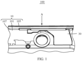
FIG. 1 is a schematic diagram of a terminal device in which a second sealing member is omitted according to an embodiment of this application; -
FIG. 2 is a partial schematic diagram of an exploded structure of the terminal device shown inFIG. 1 ; -
FIG. 3 is a partial schematic diagram of an exploded structure of the terminal device shown inFIG. 1 from another angle of view; -
FIG. 4 is a partial schematic diagram of the terminal device shown inFIG. 1 taken along direction A; -
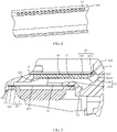
FIG. 5 is a schematic partial cross-sectional view of the terminal device shown inFIG. 1 ; -
FIG. 6 is a schematic diagram of a middle frame in the terminal device shown inFIG. 1 ; and -
FIG. 7 is a schematic diagram of a cover plate in the terminal device shown inFIG. 1 . - Terminal device: 100; middle frame: 10; first surface: 101; second surface: 103; side frame: 105; rounded transition surface: 107; sound outlet hole: 11; first groove: 12; first groove portion: 1201; second groove portion: 1203; bottom wall: 121; mounting portion: 125; third groove: 127; first through hole: 14; second groove: 15; bottom wall: 151; receiver assembly: 20; receiver: 21; first sealing member: 23; second through hole: 231; sealing assembly: 30; cover plate: 33; body: 331; engagement portion: 333; arc-shaped groove: 3331; support portion: 3333; second sealing member: 35; and third sealing member: 37.
- To further explain technical means and effects adopted in this application to achieve the intended purposes of this application, the following is described with reference to the drawings and implementations. Apparently, the described embodiments are only some embodiments rather than all the embodiments of this application.
- Unless otherwise defined, meanings of all technical and scientific terms used in this specification are the same as those usually understood by a person skilled in the art to which this application belongs. In this specification, terms used in the specification of this application are merely intended to describe objectives of the specific embodiments, but are not intended to limit this application.
- The embodiments of this application provide a terminal device. The terminal device includes a middle frame, a receiver assembly, and a sealing assembly. The middle frame includes a first surface and a second surface that are arranged opposite to each other. Sound outlet holes are arranged on the middle frame. A first groove is arranged on the first surface of the middle frame. The first groove is in communication with the sound outlet holes. A first through hole is arranged on a bottom wall of the first groove. The receiver assembly is arranged on the second surface of the middle frame. The receiver assembly is sealedly connected to the middle frame, and corresponds to the first through hole. The sealing assembly is configured to seal the first groove. In the foregoing terminal device, the first groove of the middle frame and the first through hole form a front sound cavity of the receiver assembly. The middle frame is sealedly connected to the receiver assembly, and the sealing assembly seals the first groove, so that the front sound cavity of the receiver assembly is sealed, and a sound from the receiver assembly is emitted only from the sound outlet holes on the middle frame. In this way, the cost of the sealing assembly for sealing the structure of the front sound cavity is low, and the cost of manufacturing the first groove and the first through hole on the middle frame is low.
- The following describes some implementations of this application with reference to the drawings. The following embodiments and features in the embodiments may be mutually combined in case that no conflict occurs.
- Referring to
FIG. 1 ,FIG. 2 , andFIG. 3 together, an embodiment of this application provides aterminal device 100. Theterminal device 100 is a mobile phone, but is not limited thereto. Theterminal device 100 includes amiddle frame 10, areceiver assembly 20, and a sealingassembly 30. Thereceiver assembly 20 and the sealingassembly 30 are arranged on two opposite sides of themiddle frame 10 respectively. Themiddle frame 10 includes afirst surface 101 and asecond surface 103. Thefirst surface 101 and thesecond surface 103 are arranged opposite to each other. As shown inFIG. 4 , sound outlet holes 11 are arranged on themiddle frame 10. Thereceiver assembly 20 is arranged on thesecond surface 103 of themiddle frame 10, and is sealedly connected to themiddle frame 10. Afirst groove 12 is arranged on thefirst surface 101 of themiddle frame 10. The sealingassembly 30 is configured to seal thefirst groove 12. Thefirst groove 12 is in communication with the sound outlet holes 11. A first throughhole 14 is arranged on abottom wall 121 of thefirst groove 12, and the first throughhole 14 corresponds to thereceiver assembly 20. - The
first groove 12 of themiddle frame 10 and the first throughhole 14 form a front sound cavity of thereceiver assembly 20. Themiddle frame 10 is sealedly connected to thereceiver assembly 20, and the sealingassembly 30 seals thefirst groove 12, so that the front sound cavity of thereceiver assembly 20 is sealed, and a sound from thereceiver assembly 20 is emitted only from the sound outlet holes 11 on themiddle frame 10. In this way, the cost of the sealingassembly 30 for sealing the structure of the front sound cavity is low, and the cost of manufacturing thefirst groove 12 and the first throughhole 14 that form the front sound cavity on themiddle frame 10 is low. - The
first surface 101 and thesecond surface 103 may be a flat surface, a curved surface, or a stepped surface, or a surface formed by combining the above different surfaces. Thefirst surface 101 of themiddle frame 10 is for mounting the sealingassembly 30, and is further for mounting a screen (not shown in the figures) of theterminal device 100. Thesecond surface 103 is for mounting thereceiver assembly 20, and is further for mounting other structural members of theterminal device 100. For example, the other structural members may be a camera and a circuit board (not shown in the figures). Thereceiver assembly 20 is electrically connected to the circuit board. - In the existing terminal device, a support is arranged on the
second surface 103 of themiddle frame 10, and groove structures forming a front sound cavity of a receiver are arranged on the support. Due to acoustic requirements, the space size of the front sound cavity of the receiver needs to reach a set value, to ensure stable sound transmission. A space for the front sound cavity to reach the set value needs to be provided on the support, resulting in an increased size of the support. Moreover, a demolding space for the sound outlet holes needs to be provided on a side of the support toward themiddle frame 10, which further increases the size of the support. The support occupies a large mounting space on themiddle frame 10, which may cause difficulty in the mounting and layout of the structural members of the terminal device on thesecond surface 103 of themiddle frame 10. - In the
terminal device 100 provided by this application, thereceiver assembly 20 and the sealingassembly 30 are arranged on the two opposite sides of themiddle frame 10, and thereceiver assembly 20 occupies a small space on thesecond surface 103 of themiddle frame 10. Thefirst groove 12 is arranged on thefirst surface 101, and the sealingassembly 30 is arranged in thefirst groove 12. When the sealingassembly 30 is entirely located in thefirst groove 12, the sealingassembly 30 occupies no space on thefirst surface 101. When the sealingassembly 30 is partially located in thefirst groove 12, the sealingassembly 30 occupies a small space on thefirst surface 101. - The
first groove 12 arranged on thefirst surface 101 is in communication with the sound outlet holes 11, which provides a demolding space for the sound outlet holes 11 and occupies no mounting space on thesecond surface 103 of themiddle frame 10. In this way, the mounting space of themiddle frame 10 is improved, so that themiddle frame 10 can meet more stacking requirements, for example, can meet stacking mounting requirements of a camera assembly. Referring toFIG. 2 andFIG. 5 , asecond groove 15 is arranged on thesecond surface 103 of themiddle frame 10. Thereceiver assembly 20 is arranged in thesecond groove 15. Thesecond groove 15 is in communication with thefirst groove 12 through the first throughhole 14. Thereceiver assembly 20 includes areceiver 21 and a first sealingmember 23. A second throughhole 231 is arranged on the first sealingmember 23. Thefirst sealing member 23 is adhered to abottom wall 151 of thesecond groove 15. Thereceiver 21 is arranged on the first sealingmember 23. Thereceiver 21 is sealedly connected to themiddle frame 10 by the first sealingmember 23, and is in communication with the first throughhole 14 through the second throughhole 23. A sound emitted by thereceiver 21 is transmitted from the sound outlet holes 11 after passing through the second throughhole 231, thesecond groove 15, the first throughhole 14, and thefirst groove 12. Referring toFIG. 1 andFIG. 5 , aside frame 105 is arranged on themiddle frame 10. Theside frame 105 is an annular wall structure surrounding outer sides of thefirst surface 101 and thesecond surface 103. Theside frame 105 is connected to thefirst surface 101 and thesecond surface 103. The sound outlet holes 11 are arranged on theside frame 105. The sound outlet holes 11 penetrate through theside frame 105, and are in communication with thefirst groove 12. - In a possible implementation, the
sound outlet hole 11 is a circular hole, and there are a plurality of sound outlet holes 11. As shown inFIG. 4 , a plurality of sound outlet holes 11 are arranged on theside frame 105 at intervals. - It may be understood that, in other implementations, there may alternatively be one
sound outlet hole 11, and thesound outlet hole 11 may alternatively be a rectangular long hole or of another structure. The quantity and shape of the sound outlet holes 11 may be set according requirements, as long as the sound outlet holes 11 are in communication with thefirst groove 12 to transmit the sound emitted by thereceiver 21. - Referring to
FIG. 3 andFIG. 5 , the sealingassembly 30 includes acover plate 33 and asecond sealing member 35. Thecover plate 33 is arranged in thefirst groove 12. Specifically, a protruding mountingportion 125 is arranged on thebottom wall 121 of thefirst groove 12. The mountingportion 125 is located in thefirst groove 12, and does not protrude from thefirst surface 101. Thecover plate 33 is arranged on the mountingportion 125. Thesecond sealing member 35 is arranged on a side of thecover plate 33 facing away from the mountingportion 125, and is adhered to themiddle frame 10. Thesecond sealing member 35 covers a gap between thecover plate 33 and the middle frame 10 (specifically, a side wall of the first groove 12), so that the sealingassembly 30 is sealedly connected to themiddle frame 10. - The
cover plate 33 is arranged on the mountingportion 125, so that a cavity is formed between thecover plate 33 and thebottom wall 121 of thefirst groove 12. The cavity is in communication with the first throughhole 14 and the sound outlet holes 11 respectively, thereby forming a front sound cavity of thereceiver 21. - Referring to
FIG. 6 , thefirst groove 12 includes afirst groove portion 1201 and asecond groove portion 1203 that are in communication. Thefirst groove portion 1201 is arranged on thefirst surface 101. The mountingportion 125 is arranged in thefirst groove portion 1201. The first throughhole 14 is in communication with thefirst groove portion 1201. Thesecond groove portion 1203 is located on a side of thefirst groove portion 1201 toward theside frame 105, and is located on a junction of thefirst surface 101 and theside frame 105, so that thesecond groove portion 1203 is in communication with the plurality of sound outlet holes 11. To adapt to the arrangement of the plurality of sound outlet holes 11 on theside frame 105, thesecond groove portion 1203 is partially in communication with thefirst groove portion 1201, and extends toward a side of thefirst groove portion 1201, so that thefirst groove 12 is roughly L-shaped. - Referring to
FIG. 7 , thecover plate 33 includes abody 331 and anengagement portion 333. Thebody 331 is arranged on the mountingportion 125. Theengagement portion 333 is arranged on a side of thebody 331. - Referring to
FIG. 5 , thebody 331 is arranged in thefirst groove portion 1201, and theengagement portion 333 is arranged in thesecond groove portion 1203, so that thebottom wall 121 of thefirst groove 12 and the sound outlet holes 11 are located on a same side of thecover plate 33. - The
second sealing member 35 is adhered to thefirst surface 101 of themiddle frame 10, and is adhered to theside frame 105 of themiddle frame 10. Thesecond sealing member 35 covers a gap between thecover plate 33 and thefirst surface 101 and a gap between thecover plate 33 and theside frame 105, so that the sealingassembly 30 is sealedly connected to themiddle frame 10. Thesecond groove portion 1203 extends on the junction of thefirst surface 101 and theside frame 105 along an arrangement direction of the plurality of sound outlet holes 11, thereby reducing the space occupied by thefirst groove 12 on thefirst surface 101, and reducing the impact of thefirst groove 12 on the structural design layout on thefirst surface 101 of themiddle frame 10. - A side of the
cover plate 33 facing away from thefirst groove 12 is flush with thefirst surface 101, so that the second sealingmember 35 flatly covers the gap between thecover plate 33 and themiddle frame 10, and the second sealingmember 35 can be adhered to thecover plate 33, thereby increasing the adhesion area of the second sealingmember 35, so that the second sealingmember 35 stably seals the front sound cavity of thereceiver 21. - It may be understood that, in other implementations, one side of the
cover plate 33 facing away from thefirst groove 12 may alternatively be lower or higher than thefirst surface 101, and a part of the second sealingmember 35 corresponding to thecover plate 33 is profiled to thecover plate 33, so that the second sealingmember 35 can cover the gap between thecover plate 33 and themiddle frame 10. - The
second sealing member 35 is adhered to thecover plate 33, thereby increasing the adhesion area of the second sealingmember 35, so that the second sealingmember 35 stably covers the gap between thecover plate 33 and themiddle frame 10. It may be understood that, in other implementations, there may alternatively be no connection between the second sealingmember 35 and thecover plate 33. As long as the second sealingmember 35 is adhered to themiddle frame 10 to stably cover the gap between thecover plate 33 and themiddle frame 10, it can be ensured that the sealingassembly 30 is sealedly connected to themiddle frame 10. - The first through
hole 14 is arranged in thefirst groove portion 1201 of thefirst groove 12, to provide a sound channel of thereceiver assembly 20. Thesecond groove portion 1203 is in communication with the plurality of sound outlet holes 11, to provide a demolding space for the sound outlet holes 11. - In a possible implementation, the second sealing
member 35 is of a mylar structure, but is not limited thereto. For example, in other implementations, the second sealingmember 35 may alternatively be of a sealing structure, such as, foam. - In a possible implementation, as shown in
FIG. 6 , thefirst surface 101 and theside frame 105 are connected by arounded transition surface 107. As shown inFIG. 7 , theengagement portion 333 is of an arc-shaped structure, so that a side of theengagement portion 333 facing away from thefirst groove 12 and a surface of themiddle frame 10 coincide on the junction of theside frame 105 and thefirst surface 101. Specifically, when theengagement portion 333 is arranged in thesecond groove portion 1203, a side of theengagement portion 333 toward the second sealingmember 35 is coplanar with therounded transition surface 107, making it convenient to adhere the second sealingmember 35 to thecover plate 33 and themiddle frame 10. - It may be understood that, in another possible implementation, the second sealing
member 35 may alternatively not be adhered to thefirst surface 101. For example, another groove (not shown in the figure) is arranged on themiddle frame 10, and the another groove is for accommodating the second sealingmember 35, so that the second sealingmember 35 is adhered to thefirst surface 101, therounded transition surface 107, and theside frame 105 respectively, and the second sealingmember 35 does not protrude from thefirst surface 101, thereby reducing the space occupied by the sealingassembly 30 on thefirst surface 101. - Referring to
FIG. 5 , the sealingassembly 30 further includes athird sealing member 37. Thethird sealing member 37 is adhered to the mountingportion 125. Thecover plate 33 is arranged on the third sealingmember 37. Thethird sealing member 37 enables thecover plate 33 to be sealedly connected to the mountingportion 125. Thethird sealing member 37 is roughly of a U-shaped rubber structure. Thethird sealing member 37 enables thecover plate 33 to be connected in thefirst groove 12, and achieves preliminary sealing between thecover plate 33 and themiddle frame 10. In other embodiments, the third sealingmember 37 may alternatively be omitted. Thecover plate 33 is coated with glue, and is directly adhered to the mountingportion 125. - In a possible implementation, the first sealing
member 23 and the third sealingmember 37 are of a foam structure, but are not limited thereto. It may be understood that, in another implementation, the first sealingmember 23 and/or the third sealingmember 37 may alternatively be of other structures with double-sided glue. Alternatively, in another embodiment, thereceiver 21 and thecover plate 33 may be fixed to themiddle frame 10 by means other than adhesion. For example, thereceiver 21 and thecover plate 33 are locked on themiddle frame 10 by fasteners, and a gasket for sealing is arranged between thereceiver 21 and themiddle frame 10, so that thereceiver 21 is sealedly connected to themiddle frame 10. Thecover plate 33 is sealedly connected to themiddle frame 10 by the second sealingmember 35. - The
engagement portion 333 can avoid the sound outlet holes 11, so that the sound outlet holes 11 are in communication with thefirst groove 12. In a possible implementation, theengagement portion 333 avoids some of the sound outlet holes 11. To enable theengagement portion 333 to stably avoid all of the sound outlet holes 11, arc-shapedgrooves 3331 are arranged on a side of theengagement portion 333 toward thefirst groove 12, and the arc-shapedgrooves 3331 are butted with the sound outlet holes 11. - It may be understood that, in other implementations, the
engagement portion 333 with the arc-shaped structure may alternatively avoid all of the sound outlet holes 11. For example, a thickness of theengagement portion 333 is less than a thickness of thebody 331. Theengagement portion 333 is thinned, so that a contact area between theengagement portion 333 and a groove wall of thesecond groove portion 1203 is reduced, and theengagement portion 333 does not block the sound outlet holes 11. - Referring to
FIG. 5 andFIG. 7 together,support portions 3333 are further arranged on theengagement portion 333 at intervals. Thesupport portions 3333 and the sound outlet holes 11 are staggered. Thesupport portions 3333 are in contact with themiddle frame 10. Specifically, thesupport portions 3333 are in contact with the groove wall of thesecond groove portion 1203, to improve the strength of theengagement portion 333, so that the arc-shapedengagement portion 333 is not easily deformed by collision, to avoid the problem that theengagement portion 333 blocks the sound outlet holes 11 due to deformation. - Referring to
FIG. 5 andFIG. 6 together, to increase the size of the front sound cavity of thereceiver 21, athird groove 127 is further arranged on thebottom wall 121 of thefirst groove 12. In a possible implementation, thethird groove 127 is located in thefirst groove portion 1201, and is in communication with thesecond groove portion 1203. It may be understood that, in other implementations, thethird groove 127 may be arranged in another position on thebottom wall 121 of thefirst groove 12. - In the foregoing
terminal device 100, thefirst groove 12 of themiddle frame 10 and the first throughhole 14 form the front sound cavity of thereceiver assembly 20. Themiddle frame 10 is sealedly connected to thereceiver assembly 20, and the sealingassembly 30 seals thefirst groove 12, so that the front sound cavity of thereceiver assembly 20 is sealed, and a sound from thereceiver assembly 20 is emitted only from the sound outlet holes 11 on themiddle frame 10. In this way, the cost of the sealingassembly 30 for sealing the structure of the front sound cavity is low, and the cost of manufacturing thefirst groove 12 and the first throughhole 14 on themiddle frame 10 is low. - The foregoing specific embodiments are merely intended for describing the technical solutions of this application but not for limiting this application. Although this application is described in detail with reference to the exemplary implementations, a person of ordinary skill in the art should understand that they may still make modifications or equivalent replacements to the technical solutions described in this application without departing from the spirit and essence of the technical solutions of the embodiments of this application.
Claims (10)
- A terminal device, comprising:a middle frame, comprising a first surface and a second surface, wherein the first surface and the second surface is arranged opposite to each other, and sound outlet holes are arranged on the middle frame; anda receiver assembly,wherein a first groove is arranged on the first surface of the middle frame; the first groove is in communication with the sound outlet holes, and a first through hole is arranged on a bottom wall of the first groove;the receiver assembly is arranged on the second surface of the middle frame, is sealedly connected to the middle frame, and corresponds to the first through hole; andthe terminal device further comprises a sealing assembly, and the sealing assembly is configured to seal the first groove.
- The terminal device according to claim 1, wherein the receiver assembly comprises:a receiver; anda first sealing member, arranged with a second through hole, and the second through hole is in communication with the first through hole, whereina second groove is arranged on the second surface, and the receiver is arranged in the second groove, and is sealedly connected to a bottom wall of the second groove by the first sealing member.
- The terminal device according to claim 1, wherein the sealing assembly comprises:a cover plate, arranged in the first groove; anda second sealing member, adhered to the middle frame, and covering a gap between the cover plate and the middle frame.
- The terminal device according to claim 3, wherein a protruding mounting portion is arranged in the first groove; and the sealing assembly further comprises a third sealing member, the third sealing member is arranged on the mounting portion, and the cover plate is arranged on a side of the third sealing member facing away from the mounting portion.
- The terminal device according to claim 3, wherein the middle frame further comprises a side frame, and the side frame surrounds outer sides of the first surface and the second surface, and is connected to the first surface and the second surface respectively; the sound outlet holes are arranged on the side frame;
the first groove comprises a first groove portion and a second groove portion that are in communication; the first through hole is in communication with the first groove portion; and the second groove portion is located on a junction of the first surface and the side frame, and is in communication with the sound outlet holes. - The terminal device according to claim 5, wherein the first surface and the side frame are connected by a rounded transition surface, the cover plate comprises an engagement portion with an arc-shaped structure, and the engagement portion is arranged on the second groove portion, so that the engagement portion and a surface of the middle frame coincide on the junction of the side frame and the first surface.
- The terminal device according to claim 5, wherein the cover plate comprises a body and an engagement portion, the body is arranged in the first groove portion, and the engagement portion is arranged in the second groove portion, so that the bottom wall of the first groove and the sound outlet holes are located on a same side of the cover plate.
- The terminal device according to claim 7, wherein arc-shaped grooves are arranged on the engagement portion, and the arc-shaped grooves are butted with the sound outlet holes.
- The terminal device according to claim 7, wherein protruding support portions are arranged on a side of the engagement portion toward the bottom wall of the first groove, and the support portions are in contact with a groove wall of the second groove portion.
- The terminal device according to claim 1, wherein a third groove is arranged on the bottom wall of the first groove.
Applications Claiming Priority (3)
| Application Number | Priority Date | Filing Date | Title |
|---|---|---|---|
| CN202110726884 | 2021-06-29 | ||
| CN202110777767.5A CN115550489B (en) | 2021-06-29 | 2021-07-09 | Terminal Equipment |
| PCT/CN2022/072606 WO2023273315A1 (en) | 2021-06-29 | 2022-01-18 | Terminal device |
Publications (1)
| Publication Number | Publication Date |
|---|---|
| EP4138370A1 true EP4138370A1 (en) | 2023-02-22 |
Family
ID=84690205
Family Applications (1)
| Application Number | Title | Priority Date | Filing Date |
|---|---|---|---|
| EP22753578.8A Pending EP4138370A1 (en) | 2021-06-29 | 2022-01-18 | Terminal device |
Country Status (3)
| Country | Link |
|---|---|
| US (1) | US20240130059A1 (en) |
| EP (1) | EP4138370A1 (en) |
| WO (1) | WO2023273315A1 (en) |
Family Cites Families (4)
| Publication number | Priority date | Publication date | Assignee | Title |
|---|---|---|---|---|
| JP4304008B2 (en) * | 2003-06-02 | 2009-07-29 | 京セラ株式会社 | Portable wireless terminal |
| CN109327566A (en) * | 2017-07-31 | 2019-02-12 | 深圳富泰宏精密工业有限公司 | Electronic device and its sound channel manufacturing method |
| CN111245987A (en) * | 2020-02-03 | 2020-06-05 | Oppo广东移动通信有限公司 | Terminal device |
| CN212305405U (en) * | 2020-08-10 | 2021-01-05 | 北京小米移动软件有限公司 | Terminal device |
-
2022
- 2022-01-18 EP EP22753578.8A patent/EP4138370A1/en active Pending
- 2022-01-18 WO PCT/CN2022/072606 patent/WO2023273315A1/en active Application Filing
- 2022-01-18 US US17/802,336 patent/US20240130059A1/en active Pending
Also Published As
| Publication number | Publication date |
|---|---|
| US20240130059A1 (en) | 2024-04-18 |
| WO2023273315A1 (en) | 2023-01-05 |
Similar Documents
| Publication | Publication Date | Title |
|---|---|---|
| CN108650345B (en) | Mobile terminal | |
| CN113099364A (en) | Electronic device | |
| EP3547657A1 (en) | Electronic device, terminal device, and method for controlling electronic device | |
| CN108574919B (en) | Mobile terminal | |
| US11290582B2 (en) | Mobile terminal and method for optimizing performance of an antenna module thereof | |
| US10652377B2 (en) | Electronic assembly and electronic device | |
| CN101494808A (en) | Loudspeaker assembly | |
| CN112866880B (en) | Electroacoustic transducer, loudspeaker module and electronic equipment | |
| US11057507B2 (en) | Electronic assembly and electronic device | |
| US20110212755A1 (en) | Mobile terminal device | |
| CN113709637A (en) | Electroacoustic transducer, speaker module and electronic equipment | |
| EP4138370A1 (en) | Terminal device | |
| WO2022268017A1 (en) | Electronic device | |
| CN108494919A (en) | Electronic equipment | |
| CN111835898A (en) | Electronic device | |
| CN113382592A (en) | Electronic device | |
| CN115132098B (en) | Electronic equipment and display module thereof | |
| CN115550489B (en) | Terminal Equipment | |
| WO2019129191A1 (en) | Electronic module, electronic device, and assembly method for electronic device | |
| WO2022171059A1 (en) | Device casing and electronic device | |
| EP4064659A1 (en) | Middle frame and terminal | |
| US10244326B2 (en) | Miniature sounder | |
| CN209748624U (en) | Electronic equipment and earphone assembly thereof | |
| CN216700052U (en) | Shell structure and electronic equipment | |
| CN216673066U (en) | Electronic device |
Legal Events
| Date | Code | Title | Description |
|---|---|---|---|
| STAA | Information on the status of an ep patent application or granted ep patent |
Free format text: STATUS: UNKNOWN |
|
| STAA | Information on the status of an ep patent application or granted ep patent |
Free format text: STATUS: THE INTERNATIONAL PUBLICATION HAS BEEN MADE |
|
| PUAI | Public reference made under article 153(3) epc to a published international application that has entered the european phase |
Free format text: ORIGINAL CODE: 0009012 |
|
| STAA | Information on the status of an ep patent application or granted ep patent |
Free format text: STATUS: REQUEST FOR EXAMINATION WAS MADE |
|
| 17P | Request for examination filed |
Effective date: 20220822 |
|
| AK | Designated contracting states |
Kind code of ref document: A1 Designated state(s): AL AT BE BG CH CY CZ DE DK EE ES FI FR GB GR HR HU IE IS IT LI LT LU LV MC MK MT NL NO PL PT RO RS SE SI SK SM TR |