EP4138239B1 - Support bracket for cable trays - Google Patents
Support bracket for cable trays Download PDFInfo
- Publication number
- EP4138239B1 EP4138239B1 EP21720796.8A EP21720796A EP4138239B1 EP 4138239 B1 EP4138239 B1 EP 4138239B1 EP 21720796 A EP21720796 A EP 21720796A EP 4138239 B1 EP4138239 B1 EP 4138239B1
- Authority
- EP
- European Patent Office
- Prior art keywords
- support bracket
- arm
- central partition
- opening
- holes
- Prior art date
- Legal status (The legal status is an assumption and is not a legal conclusion. Google has not performed a legal analysis and makes no representation as to the accuracy of the status listed.)
- Active
Links
Images


Classifications
-
- H—ELECTRICITY
- H02—GENERATION; CONVERSION OR DISTRIBUTION OF ELECTRIC POWER
- H02G—INSTALLATION OF ELECTRIC CABLES OR LINES, OR OF COMBINED OPTICAL AND ELECTRIC CABLES OR LINES
- H02G3/00—Installations of electric cables or lines or protective tubing therefor in or on buildings, equivalent structures or vehicles
- H02G3/26—Installations of cables, lines, or separate protective tubing therefor directly on or in walls, ceilings, or floors
- H02G3/263—Installation, e.g. suspension, of conduit channels or other supports
-
- H—ELECTRICITY
- H02—GENERATION; CONVERSION OR DISTRIBUTION OF ELECTRIC POWER
- H02G—INSTALLATION OF ELECTRIC CABLES OR LINES, OR OF COMBINED OPTICAL AND ELECTRIC CABLES OR LINES
- H02G3/00—Installations of electric cables or lines or protective tubing therefor in or on buildings, equivalent structures or vehicles
- H02G3/30—Installations of cables or lines on walls, floors or ceilings
Definitions
- the invention is comprised in the field of cable tray devices which are used for guiding electric cables, fiber-optic cables, or cables of another type.
- the invention particularly relates to a support bracket which is fixed to a vertical support surface and intended for supporting a cable tray seated on said support bracket.
- the invention relates to a support bracket for cable trays, formed by a one-piece body made of a polymer material and comprising:
- a support bar structure which serves to support cable trays, as well as to directly fix some individual cables or small cable bundles to said support bars, is often built to install cables in a technical space, such as an industrial warehouse, for example.
- This structure usually comprises vertical support bars which are normally used for fixing support brackets on which cable trays are seated. These support brackets are fixed to the vertical support bars by means of fixing screws.
- the support brackets can also be fixed to other vertical support surfaces, such as a vertical wall, for example. Fixing screws which traverse the through holes of the upper wall of the arm are used to fix a tray of a cable tray to a support bracket. Normally, each fixing screw is screwed into a nut which rests on the lower face of the upper wall of the arm and must be positioned by the user.
- This operation of positioning the nut and screwing the fixing screw in said nut is not always an easy one.
- the placement and fixing of a cable tray on/to a support bracket is often performed in hard-to-access places, with space restrictions and possibly at a great height. To that end, it is important for the installation operations to be performed as easily as possible.
- US2011062292A1 discloses a support bracket of the type described in the preamble of claim 1.
- CN201475498 discloses a support bracket with an upper wall, a lower wall and a central partition.
- the purpose of the invention is to provide a support bracket for cable trays of the type indicated above, allowing the installer to more easily perform the operations required for fixing a cable tray to the support bracket, without complicating the manufacture of the support bracket or making it more expensive.
- a support bracket as defined in claim 1.
- the through opening thus arranged in the central partition allows the user to introduce his or her finger through same to thereby comfortably access the through holes, below the upper wall of the arm from the two sides of said arm. This considerably facilitates the operation that the user must perform for placing the nut into which the fixing screw is screwed. Furthermore, this configuration allows designing a support bracket in which the through holes take up a centered position in a mid-plane of the arm.
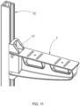
- the terms “horizontal” and “vertical” must be understood in a usage position of the support bracket, like the one shown in Figure 13 , in which the support bracket is fixed by the base thereof to a vertical support surface, such as a vertical support bar like the one shown in said figure, for example.
- a vertical support surface such as a vertical support bar like the one shown in said figure, for example.
- the oblong upper face of the upper wall of the arm is in a horizontal plane.
- the support bracket is made of an electrically insulating polymer material, such as PVC (polyvinyl chloride), for example, with a surface resistivity exceeding 100 M ⁇ (surface resistivity measured according to the EN 62631-3-2:2016 standard), and which can optionally be filled with reinforcement fibers.
- PVC polyvinyl chloride
- the central partition comprises a transverse wing extending in a cantilever manner on both sides of said central partition and forming a perimetral wall of said through opening.
- This transverse wing increases the moment of inertia of the arm and thereby compensates for the loss of mechanical strength of the arm caused by the through opening in the central partition.
- the transverse wing makes it more comfortable for the user to place the nut because the user can rest his or her fingers against the surface of the transverse wing.
- the transverse wing is continuous and has two ends, each of them attached to the upper wall, such that said transverse wing extends continuously along the entire portion of the perimeter of the through opening arranged in the central partition.
- the transverse wing thus configured satisfactorily provides the mechanical reinforcement function throughout the entire through opening, and also serves as a support for the user to rest his or her fingers along the entire length of said through opening.
- the width of the transverse wing in a direction transverse to the central partition, decreases from each of the two ends of said transverse wing towards a central portion between said two ends.
- This configuration provides easier access to a central portion of the through opening for the placement of the nut, particularly when the user accesses from a lower position with his or her fingers.
- said at least one through hole coming into the empty space contained in the through opening is an oblong hole extending on both sides of the central partition in a direction transverse to said central partition.
- the oblong hole in the transverse direction allows placing the fixing screw in a variable transverse position to align it with the holes available in the cable tray.
- the user can access the corresponding nut with his or her fingers from either of the two sides of the central partition.
- the user can thereby manipulate, from one side of the central partition, a nut arranged on the other side of said central partition along the oblong through hole.
- the support bracket comprises at least two of said through holes coming into the empty space contained in the through opening, said two through holes being separated from one another in the horizontal longitudinal direction of the arm. Therefore, the user has more options for aligning one of these through holes with the holes available in the cable tray.
- the support bracket comprises at least two of said through openings separated from one another in the horizontal longitudinal direction of the arm, each of said through openings being located below at least one of said through holes and containing said empty space into which said through hole comes.
- the invention also comprises other detail features shown in the following detailed description of an embodiment of the invention and in the attached figures.
- FIGS 1 to 10 show a first embodiment of the support bracket according to the invention.
- the support bracket 1 is formed by a one-piece body made of a polymer material obtained by molding.
- the polymer material from which the support bracket 1 is molded is an electrically insulating material.
- the polymer material can be a thermoplastic such as PVC or a thermosetting resin, for example.
- the support bracket 1 is mainly intended for being fixed to a vertical support surface, such as the bar 12 shown in Figures 11 to 13 or other bar types, for example.
- the support bracket 1 can also be fixed to other vertical support surfaces, such as a vertical wall, for example.
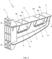
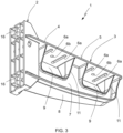
- the support bracket 1 comprises a base 2 for fixing said support bracket 1 to a vertical support surface, such as the vertical support bar 12 shown in Figures 11 to 13 , for example, and an arm 3 extending in a cantilever manner from said base 2 and intended for supporting a cable tray, such as the cable tray 13 shown in Figures 12 and 13 , for example, which is seated on said arm 3.
- the base 2 can have shapes other than the ones shown in the figures, suitable for fixing the support bracket 1 to different types of vertical support surface.
- the arm 3 comprises an upper wall 4 with an oblong upper face 5 extending in a horizontal plane in a horizontal longitudinal direction of said arm 3, a lower wall 8 opposite said upper wall 4, and a central partition 7 joining said upper wall 4 and said lower wall 8.
- the oblong upper face 5 forms a seating surface for a cable tray which is seated on said upper face 5.
- the upper wall 4 is provided with through holes 6a, 6b for the passage of fixing screws for fixing a cable tray to the support bracket 1.
- the upper wall 4 has oblong through holes 6a extending on both sides of the central partition 7 in a direction transverse to said central partition 7, and circular through holes 6b.
- the oblong through holes 6a are grouped in two pairs. The two oblong through holes 6a of each pair are separated from one another in the horizontal longitudinal direction of the arm 3, and a circular through hole 6b is arranged between them.
- the oblong through holes 6a can advantageously be used for fixing to the support bracket 1 a cable tray 13 like the one shown in Figures 12 and 13 , having a continuous bottom wall provided with holes uniformly distributed therein.
- the oblong nature of the through holes 6a allows one of them to be more readily aligned with one of the holes of the cable tray 13 for passing the fixing screw 14 therethrough.
- the circular through holes 6b can be used for fixing to the support bracket 1 a ladder-type cable tray, formed by two parallel longitudinal members joined by a series of cross members forming a discontinuous bottom wall.
- a securing device is often used, said device being fixed to the support bracket 1 by means of a screw or another fixing element through the circular through hole 6b and applying pressure on a cross member of the cable ladder.
- the central partition 7 has two through openings 9 adjacent to the upper wall 4. Each of these two through openings 9 is located below a group formed by two oblong through holes 6a and a circular through hole 6b arranged between them and contains an empty space 10 into which the three through holes 6a, 6b of the group come.
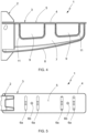
- the empty space 10 into which the through holes 6a, 6b come is a rectangular parallelepiped with a width W, in the horizontal longitudinal direction of the arm 3, greater than or equal to 4 cm, and a height H, in a vertical direction orthogonal to said horizontal longitudinal direction, greater than or equal to 2 cm.
- the empty space 10 of each through opening 9 has been indicated with a discontinuous line in Figure 8 .
- the empty space 10 has a width W of 8 cm and a height H of 3 cm.
- the central partition 7 comprises, in each through opening 9, a transverse wing 11 extending in a cantilever manner on both sides of said central partition 7 forming a perimetral wall of said through opening 9.
- the transverse wing 11 is continuous from one of the ends thereof attached to the upper wall 4 to the other one of the ends thereof also attached to said upper wall 4.
- the transverse wing 11 thereby extends continuously along the entire portion of the perimeter of the through opening 9 arranged in the central partition 7.
- each through opening 9 has an overall rectangular shape, with a lower side facing the upper wall 4 and slightly inclined with respect to same, and two lateral sides extending from the upper wall 4 orthogonal thereto and forming rounded corners with the lower side.
- This particular shape of the through opening 9 results from a design choice made taking into account esthetic, not technical, criteria, where many different shapes such as, for example, the shape of the third embodiment shown in Figures 16 and 17 , have been taken into consideration among other possible designs.
- the transverse wing 11 On the lower side of the through opening 9, the transverse wing 11 has a constant width, and this width increases progressively from the corners and along the two lateral sides until intersecting with the upper wall 4, where said width is maximum and is almost the same as the width of the upper wall 4.
- the lower wall 8 forms a rounded elbow and is joined to the upper wall 4 at the free end of the arm 3.
- Figure 11 shows, by way of example, the support bracket 1 fixed to a vertical support bar made up of a profile extruded from a polymer material.
- fixing is performed by means of screws 17 that go through through holes 16 provided in the base 2.
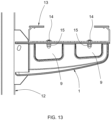
- Figures 12 and 13 show a cable tray 13 fixed to the support bracket 1.
- the cable tray 13 is seated on the upper face 5 of the arm 3 and fixed thereto by means of fixing screws 14 going through some of the through holes 6a, 6b of the upper wall 4 of said arm 3.
- Each fixing screw 14 is screwed into a nut 15 arranged against the lower face of the upper wall 4.
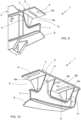
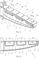
- Figures 14 and 15 show a second embodiment of the support bracket 1. This second embodiment differs from the first embodiment essentially in that the arm 3 is longer and has three through openings 9, and in that the through holes 6a, 6b are distributed in a different way.
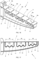
- Figures 16 and 17 show a third embodiment of the support bracket 1 differing from the second embodiment only by the shape of the through openings 9.
- the lower side of the through openings 9 is not straight, but rather is wavy.
Landscapes
- Engineering & Computer Science (AREA)
- Architecture (AREA)
- Civil Engineering (AREA)
- Structural Engineering (AREA)
- Details Of Indoor Wiring (AREA)
- Installation Of Indoor Wiring (AREA)
- Laying Of Electric Cables Or Lines Outside (AREA)
Applications Claiming Priority (2)
| Application Number | Priority Date | Filing Date | Title |
|---|---|---|---|
| ES202030662U ES1248154Y (es) | 2020-04-17 | 2020-04-17 | Escuadra de soporte para bandejas portacables |
| PCT/ES2021/070244 WO2021209666A1 (es) | 2020-04-17 | 2021-04-14 | Escuadra de soporte para bandejas portacables |
Publications (3)
| Publication Number | Publication Date |
|---|---|
| EP4138239A1 EP4138239A1 (en) | 2023-02-22 |
| EP4138239B1 true EP4138239B1 (en) | 2025-01-01 |
| EP4138239C0 EP4138239C0 (en) | 2025-01-01 |
Family
ID=71898947
Family Applications (1)
| Application Number | Title | Priority Date | Filing Date |
|---|---|---|---|
| EP21720796.8A Active EP4138239B1 (en) | 2020-04-17 | 2021-04-14 | Support bracket for cable trays |
Country Status (5)
| Country | Link |
|---|---|
| EP (1) | EP4138239B1 (pl) |
| CN (1) | CN115552747B (pl) |
| ES (2) | ES1248154Y (pl) |
| PL (1) | PL4138239T3 (pl) |
| WO (1) | WO2021209666A1 (pl) |
Families Citing this family (1)
| Publication number | Priority date | Publication date | Assignee | Title |
|---|---|---|---|---|
| CN114421380B (zh) * | 2021-12-04 | 2023-07-11 | 中铁九局集团第五工程有限公司 | 一种公路桥梁电缆托架 |
Citations (4)
| Publication number | Priority date | Publication date | Assignee | Title |
|---|---|---|---|---|
| CN201827518U (zh) * | 2010-08-27 | 2011-05-11 | 江苏源盛复合材料技术股份有限公司 | 一种复合材料电缆支架 |
| CN202580307U (zh) * | 2012-04-28 | 2012-12-05 | 宁波华缘玻璃钢电器制造有限公司 | 电缆支架 |
| EP2388876B1 (en) * | 2010-05-18 | 2013-06-26 | Unex Aparellaje Electrico S.L. | Wall support for electrical conductor carrier trays |
| USD851482S1 (en) * | 2016-12-02 | 2019-06-18 | Michael Ferman | Bracket |
Family Cites Families (9)
| Publication number | Priority date | Publication date | Assignee | Title |
|---|---|---|---|---|
| ES238421Y (es) * | 1978-09-28 | 1979-04-01 | Aparellaje Electrico, S.A. | Soporte para canalizaciones electricas. |
| DE3809079A1 (de) * | 1988-03-18 | 1988-08-11 | Rieth & Co | Ausleger fuer trag- oder aufhaengevorrichtungen fuer kabel, rohre u. dgl. |
| JP2002325331A (ja) * | 2001-04-23 | 2002-11-08 | Matsushita Electric Works Ltd | ブラケット |
| CN201475498U (zh) * | 2009-09-08 | 2010-05-19 | 广州宏能电力技术开发有限公司 | 复合材料电缆支撑架 |
| US8567734B2 (en) * | 2009-09-14 | 2013-10-29 | Underground Devices, Inc | Cable support system |
| CN204114354U (zh) * | 2014-09-23 | 2015-01-21 | 羊慧芳 | 一种螺钉式玻璃纤维增强塑料电缆支架 |
| CN107458415B (zh) * | 2016-06-02 | 2019-08-09 | 株洲时代新材料科技股份有限公司 | 一种低地板车转动铰的上底座及安装方法 |
| US10186850B1 (en) * | 2017-10-02 | 2019-01-22 | Electrical Materials Company | Non-metallic electrical cable support arrangement |
| CN110635413B (zh) * | 2019-10-23 | 2020-12-15 | 中国商用飞机有限责任公司 | 可预埋螺母的多通道线缆固定装置 |
-
2020
- 2020-04-17 ES ES202030662U patent/ES1248154Y/es active Active
-
2021
- 2021-04-14 PL PL21720796.8T patent/PL4138239T3/pl unknown
- 2021-04-14 CN CN202180028895.8A patent/CN115552747B/zh active Active
- 2021-04-14 WO PCT/ES2021/070244 patent/WO2021209666A1/es not_active Ceased
- 2021-04-14 ES ES21720796T patent/ES3017426T3/es active Active
- 2021-04-14 EP EP21720796.8A patent/EP4138239B1/en active Active
Patent Citations (4)
| Publication number | Priority date | Publication date | Assignee | Title |
|---|---|---|---|---|
| EP2388876B1 (en) * | 2010-05-18 | 2013-06-26 | Unex Aparellaje Electrico S.L. | Wall support for electrical conductor carrier trays |
| CN201827518U (zh) * | 2010-08-27 | 2011-05-11 | 江苏源盛复合材料技术股份有限公司 | 一种复合材料电缆支架 |
| CN202580307U (zh) * | 2012-04-28 | 2012-12-05 | 宁波华缘玻璃钢电器制造有限公司 | 电缆支架 |
| USD851482S1 (en) * | 2016-12-02 | 2019-06-18 | Michael Ferman | Bracket |
Also Published As
| Publication number | Publication date |
|---|---|
| ES1248154U (es) | 2020-07-01 |
| CN115552747A (zh) | 2022-12-30 |
| ES3017426T3 (en) | 2025-05-12 |
| PL4138239T3 (pl) | 2025-05-26 |
| ES1248154Y (es) | 2020-09-22 |
| CN115552747B (zh) | 2025-09-23 |
| WO2021209666A1 (es) | 2021-10-21 |
| EP4138239C0 (en) | 2025-01-01 |
| EP4138239A1 (en) | 2023-02-22 |
Similar Documents
| Publication | Publication Date | Title |
|---|---|---|
| US8435086B2 (en) | Vertical cable manager | |
| US6427952B2 (en) | Cable management ring | |
| US5023404A (en) | Wiring duct | |
| US5239132A (en) | Strap for retaining junction box | |
| EP1315261B1 (en) | A joining member for a mesh cable tray | |
| US20120211609A1 (en) | Cable Support and Methods of Supporting Cables | |
| EP4138239B1 (en) | Support bracket for cable trays | |
| US20110030992A1 (en) | Compact Spillover Fitting and Method of Use Thereof | |
| US6520345B1 (en) | Self-squaring relay rack assembly | |
| US10673219B2 (en) | Electrical box cable connector | |
| EP4136722B1 (en) | Support bracket for cable trays | |
| JP2021013230A (ja) | 配索材固定体 | |
| US6572058B1 (en) | Multiple cable support bracket | |
| US11594866B2 (en) | Cable tray barrier strip | |
| KR200493672Y1 (ko) | 산업용 선반의 패널 가이드 파이프 | |
| US6024329A (en) | Support device for a cableway | |
| EP4123852B1 (en) | Support bar for cable trays | |
| US4787585A (en) | Adapter support | |
| EP4340146A1 (en) | Mesh cable tray | |
| EP4122673B1 (en) | Support bar for cable trays | |
| JP2524636B2 (ja) | フロアパネルおよびフロアパネル装置 | |
| KR102835744B1 (ko) | 케이블 거치대 | |
| KR20250169839A (ko) | 전기선의 안전보호와 제조효율 및 설치의 용이성을 향상시킨 접지형 레이스웨이 조립체 | |
| JPS5927651Y2 (ja) | 回路基板用固定具 | |
| JP2019019936A (ja) | 長尺体用支持具 |
Legal Events
| Date | Code | Title | Description |
|---|---|---|---|
| STAA | Information on the status of an ep patent application or granted ep patent |
Free format text: STATUS: UNKNOWN |
|
| STAA | Information on the status of an ep patent application or granted ep patent |
Free format text: STATUS: THE INTERNATIONAL PUBLICATION HAS BEEN MADE |
|
| PUAI | Public reference made under article 153(3) epc to a published international application that has entered the european phase |
Free format text: ORIGINAL CODE: 0009012 |
|
| STAA | Information on the status of an ep patent application or granted ep patent |
Free format text: STATUS: REQUEST FOR EXAMINATION WAS MADE |
|
| 17P | Request for examination filed |
Effective date: 20221108 |
|
| AK | Designated contracting states |
Kind code of ref document: A1 Designated state(s): AL AT BE BG CH CY CZ DE DK EE ES FI FR GB GR HR HU IE IS IT LI LT LU LV MC MK MT NL NO PL PT RO RS SE SI SK SM TR |
|
| DAX | Request for extension of the european patent (deleted) | ||
| RAV | Requested validation state of the european patent: fee paid |
Extension state: MA Effective date: 20221108 |
|
| GRAP | Despatch of communication of intention to grant a patent |
Free format text: ORIGINAL CODE: EPIDOSNIGR1 |
|
| STAA | Information on the status of an ep patent application or granted ep patent |
Free format text: STATUS: GRANT OF PATENT IS INTENDED |
|
| INTG | Intention to grant announced |
Effective date: 20240830 |
|
| GRAS | Grant fee paid |
Free format text: ORIGINAL CODE: EPIDOSNIGR3 |
|
| GRAA | (expected) grant |
Free format text: ORIGINAL CODE: 0009210 |
|
| STAA | Information on the status of an ep patent application or granted ep patent |
Free format text: STATUS: THE PATENT HAS BEEN GRANTED |
|
| AK | Designated contracting states |
Kind code of ref document: B1 Designated state(s): AL AT BE BG CH CY CZ DE DK EE ES FI FR GB GR HR HU IE IS IT LI LT LU LV MC MK MT NL NO PL PT RO RS SE SI SK SM TR |
|
| REG | Reference to a national code |
Ref country code: GB Ref legal event code: FG4D |
|
| REG | Reference to a national code |
Ref country code: CH Ref legal event code: EP |
|
| REG | Reference to a national code |
Ref country code: DE Ref legal event code: R096 Ref document number: 602021024249 Country of ref document: DE |
|
| REG | Reference to a national code |
Ref country code: IE Ref legal event code: FG4D |
|
| U01 | Request for unitary effect filed |
Effective date: 20250114 |
|
| U07 | Unitary effect registered |
Designated state(s): AT BE BG DE DK EE FI FR IT LT LU LV MT NL PT RO SE SI Effective date: 20250120 |
|
| PGFP | Annual fee paid to national office [announced via postgrant information from national office to epo] |
Ref country code: GB Payment date: 20250311 Year of fee payment: 5 |
|
| REG | Reference to a national code |
Ref country code: ES Ref legal event code: FG2A Ref document number: 3017426 Country of ref document: ES Kind code of ref document: T3 Effective date: 20250512 |
|
| U21 | Renewal fee for the european patent with unitary effect paid with additional fee |
Year of fee payment: 5 Effective date: 20250507 |
|
| PGFP | Annual fee paid to national office [announced via postgrant information from national office to epo] |
Ref country code: PL Payment date: 20250214 Year of fee payment: 5 |
|
| PG25 | Lapsed in a contracting state [announced via postgrant information from national office to epo] |
Ref country code: IS Free format text: LAPSE BECAUSE OF FAILURE TO SUBMIT A TRANSLATION OF THE DESCRIPTION OR TO PAY THE FEE WITHIN THE PRESCRIBED TIME-LIMIT Effective date: 20250501 Ref country code: NO Free format text: LAPSE BECAUSE OF FAILURE TO SUBMIT A TRANSLATION OF THE DESCRIPTION OR TO PAY THE FEE WITHIN THE PRESCRIBED TIME-LIMIT Effective date: 20250401 |
|
| PG25 | Lapsed in a contracting state [announced via postgrant information from national office to epo] |
Ref country code: HR Free format text: LAPSE BECAUSE OF FAILURE TO SUBMIT A TRANSLATION OF THE DESCRIPTION OR TO PAY THE FEE WITHIN THE PRESCRIBED TIME-LIMIT Effective date: 20250101 |
|
| PG25 | Lapsed in a contracting state [announced via postgrant information from national office to epo] |
Ref country code: GR Free format text: LAPSE BECAUSE OF FAILURE TO SUBMIT A TRANSLATION OF THE DESCRIPTION OR TO PAY THE FEE WITHIN THE PRESCRIBED TIME-LIMIT Effective date: 20250402 |
|
| PGFP | Annual fee paid to national office [announced via postgrant information from national office to epo] |
Ref country code: CH Payment date: 20250501 Year of fee payment: 5 |
|
| PG25 | Lapsed in a contracting state [announced via postgrant information from national office to epo] |
Ref country code: CZ Free format text: LAPSE BECAUSE OF FAILURE TO SUBMIT A TRANSLATION OF THE DESCRIPTION OR TO PAY THE FEE WITHIN THE PRESCRIBED TIME-LIMIT Effective date: 20250101 |
|
| PG25 | Lapsed in a contracting state [announced via postgrant information from national office to epo] |
Ref country code: SM Free format text: LAPSE BECAUSE OF FAILURE TO SUBMIT A TRANSLATION OF THE DESCRIPTION OR TO PAY THE FEE WITHIN THE PRESCRIBED TIME-LIMIT Effective date: 20250101 |
|
| PGFP | Annual fee paid to national office [announced via postgrant information from national office to epo] |
Ref country code: ES Payment date: 20250711 Year of fee payment: 5 |
|
| PG25 | Lapsed in a contracting state [announced via postgrant information from national office to epo] |
Ref country code: SK Free format text: LAPSE BECAUSE OF FAILURE TO SUBMIT A TRANSLATION OF THE DESCRIPTION OR TO PAY THE FEE WITHIN THE PRESCRIBED TIME-LIMIT Effective date: 20250101 |
|
| PLBE | No opposition filed within time limit |
Free format text: ORIGINAL CODE: 0009261 |
|
| STAA | Information on the status of an ep patent application or granted ep patent |
Free format text: STATUS: NO OPPOSITION FILED WITHIN TIME LIMIT |