EP4138178A1 - Lower case of battery module having cooling block and manufacturing method thereof - Google Patents
Lower case of battery module having cooling block and manufacturing method thereof Download PDFInfo
- Publication number
- EP4138178A1 EP4138178A1 EP22191122.5A EP22191122A EP4138178A1 EP 4138178 A1 EP4138178 A1 EP 4138178A1 EP 22191122 A EP22191122 A EP 22191122A EP 4138178 A1 EP4138178 A1 EP 4138178A1
- Authority
- EP
- European Patent Office
- Prior art keywords
- lower case
- cooling block
- cooling
- battery module
- block
- Prior art date
- Legal status (The legal status is an assumption and is not a legal conclusion. Google has not performed a legal analysis and makes no representation as to the accuracy of the status listed.)
- Granted
Links
Images


Classifications
-
- H—ELECTRICITY
- H01—ELECTRIC ELEMENTS
- H01M—PROCESSES OR MEANS, e.g. BATTERIES, FOR THE DIRECT CONVERSION OF CHEMICAL ENERGY INTO ELECTRICAL ENERGY
- H01M10/00—Secondary cells; Manufacture thereof
- H01M10/60—Heating or cooling; Temperature control
- H01M10/65—Means for temperature control structurally associated with the cells
- H01M10/655—Solid structures for heat exchange or heat conduction
- H01M10/6556—Solid parts with flow channel passages or pipes for heat exchange
-
- H—ELECTRICITY
- H01—ELECTRIC ELEMENTS
- H01M—PROCESSES OR MEANS, e.g. BATTERIES, FOR THE DIRECT CONVERSION OF CHEMICAL ENERGY INTO ELECTRICAL ENERGY
- H01M10/00—Secondary cells; Manufacture thereof
- H01M10/60—Heating or cooling; Temperature control
- H01M10/61—Types of temperature control
- H01M10/613—Cooling or keeping cold
-
- H—ELECTRICITY
- H01—ELECTRIC ELEMENTS
- H01M—PROCESSES OR MEANS, e.g. BATTERIES, FOR THE DIRECT CONVERSION OF CHEMICAL ENERGY INTO ELECTRICAL ENERGY
- H01M10/00—Secondary cells; Manufacture thereof
- H01M10/60—Heating or cooling; Temperature control
- H01M10/62—Heating or cooling; Temperature control specially adapted for specific applications
- H01M10/625—Vehicles
-
- H—ELECTRICITY
- H01—ELECTRIC ELEMENTS
- H01M—PROCESSES OR MEANS, e.g. BATTERIES, FOR THE DIRECT CONVERSION OF CHEMICAL ENERGY INTO ELECTRICAL ENERGY
- H01M10/00—Secondary cells; Manufacture thereof
- H01M10/60—Heating or cooling; Temperature control
- H01M10/64—Heating or cooling; Temperature control characterised by the shape of the cells
- H01M10/647—Prismatic or flat cells, e.g. pouch cells
-
- H—ELECTRICITY
- H01—ELECTRIC ELEMENTS
- H01M—PROCESSES OR MEANS, e.g. BATTERIES, FOR THE DIRECT CONVERSION OF CHEMICAL ENERGY INTO ELECTRICAL ENERGY
- H01M10/00—Secondary cells; Manufacture thereof
- H01M10/60—Heating or cooling; Temperature control
- H01M10/65—Means for temperature control structurally associated with the cells
- H01M10/656—Means for temperature control structurally associated with the cells characterised by the type of heat-exchange fluid
- H01M10/6567—Liquids
-
- H—ELECTRICITY
- H01—ELECTRIC ELEMENTS
- H01M—PROCESSES OR MEANS, e.g. BATTERIES, FOR THE DIRECT CONVERSION OF CHEMICAL ENERGY INTO ELECTRICAL ENERGY
- H01M50/00—Constructional details or processes of manufacture of the non-active parts of electrochemical cells other than fuel cells, e.g. hybrid cells
- H01M50/20—Mountings; Secondary casings or frames; Racks, modules or packs; Suspension devices; Shock absorbers; Transport or carrying devices; Holders
- H01M50/204—Racks, modules or packs for multiple batteries or multiple cells
- H01M50/207—Racks, modules or packs for multiple batteries or multiple cells characterised by their shape
- H01M50/209—Racks, modules or packs for multiple batteries or multiple cells characterised by their shape adapted for prismatic or rectangular cells
-
- H—ELECTRICITY
- H01—ELECTRIC ELEMENTS
- H01M—PROCESSES OR MEANS, e.g. BATTERIES, FOR THE DIRECT CONVERSION OF CHEMICAL ENERGY INTO ELECTRICAL ENERGY
- H01M50/00—Constructional details or processes of manufacture of the non-active parts of electrochemical cells other than fuel cells, e.g. hybrid cells
- H01M50/20—Mountings; Secondary casings or frames; Racks, modules or packs; Suspension devices; Shock absorbers; Transport or carrying devices; Holders
- H01M50/218—Mountings; Secondary casings or frames; Racks, modules or packs; Suspension devices; Shock absorbers; Transport or carrying devices; Holders characterised by the material
- H01M50/22—Mountings; Secondary casings or frames; Racks, modules or packs; Suspension devices; Shock absorbers; Transport or carrying devices; Holders characterised by the material of the casings or racks
- H01M50/222—Inorganic material
- H01M50/224—Metals
-
- H—ELECTRICITY
- H01—ELECTRIC ELEMENTS
- H01M—PROCESSES OR MEANS, e.g. BATTERIES, FOR THE DIRECT CONVERSION OF CHEMICAL ENERGY INTO ELECTRICAL ENERGY
- H01M50/00—Constructional details or processes of manufacture of the non-active parts of electrochemical cells other than fuel cells, e.g. hybrid cells
- H01M50/20—Mountings; Secondary casings or frames; Racks, modules or packs; Suspension devices; Shock absorbers; Transport or carrying devices; Holders
- H01M50/249—Mountings; Secondary casings or frames; Racks, modules or packs; Suspension devices; Shock absorbers; Transport or carrying devices; Holders specially adapted for aircraft or vehicles, e.g. cars or trains
-
- H—ELECTRICITY
- H01—ELECTRIC ELEMENTS
- H01M—PROCESSES OR MEANS, e.g. BATTERIES, FOR THE DIRECT CONVERSION OF CHEMICAL ENERGY INTO ELECTRICAL ENERGY
- H01M50/00—Constructional details or processes of manufacture of the non-active parts of electrochemical cells other than fuel cells, e.g. hybrid cells
- H01M50/20—Mountings; Secondary casings or frames; Racks, modules or packs; Suspension devices; Shock absorbers; Transport or carrying devices; Holders
- H01M50/258—Modular batteries; Casings provided with means for assembling
-
- H—ELECTRICITY
- H01—ELECTRIC ELEMENTS
- H01M—PROCESSES OR MEANS, e.g. BATTERIES, FOR THE DIRECT CONVERSION OF CHEMICAL ENERGY INTO ELECTRICAL ENERGY
- H01M50/00—Constructional details or processes of manufacture of the non-active parts of electrochemical cells other than fuel cells, e.g. hybrid cells
- H01M50/20—Mountings; Secondary casings or frames; Racks, modules or packs; Suspension devices; Shock absorbers; Transport or carrying devices; Holders
- H01M50/262—Mountings; Secondary casings or frames; Racks, modules or packs; Suspension devices; Shock absorbers; Transport or carrying devices; Holders with fastening means, e.g. locks
-
- H—ELECTRICITY
- H01—ELECTRIC ELEMENTS
- H01M—PROCESSES OR MEANS, e.g. BATTERIES, FOR THE DIRECT CONVERSION OF CHEMICAL ENERGY INTO ELECTRICAL ENERGY
- H01M2220/00—Batteries for particular applications
- H01M2220/20—Batteries in motive systems, e.g. vehicle, ship, plane
-
- Y—GENERAL TAGGING OF NEW TECHNOLOGICAL DEVELOPMENTS; GENERAL TAGGING OF CROSS-SECTIONAL TECHNOLOGIES SPANNING OVER SEVERAL SECTIONS OF THE IPC; TECHNICAL SUBJECTS COVERED BY FORMER USPC CROSS-REFERENCE ART COLLECTIONS [XRACs] AND DIGESTS
- Y02—TECHNOLOGIES OR APPLICATIONS FOR MITIGATION OR ADAPTATION AGAINST CLIMATE CHANGE
- Y02E—REDUCTION OF GREENHOUSE GAS [GHG] EMISSIONS, RELATED TO ENERGY GENERATION, TRANSMISSION OR DISTRIBUTION
- Y02E60/00—Enabling technologies; Technologies with a potential or indirect contribution to GHG emissions mitigation
- Y02E60/10—Energy storage using batteries
Definitions
- the present disclosure relates to a lower case in which a battery module is mounted, and more particularly, to a battery module lower case to which a cooling block having a cooling water flow path is attached.
- a heat sink and a heat sink frame are separately made and combined to manufacture a single battery tray, a battery is disposed between two battery trays manufactured in this way, and then the battery trays are bound with a band clamp.
- FIG. 1 shows a water-cooled battery module according to the above-described disclosure
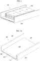
- FIGS. 2A and 2B show a lower case from which the battery module is separated.
- the lower case 200 is configured of a lower horizontal plate 220 and side plates 240 that stand vertically on both sides of the lower horizontal plate 220, and has a module mounting space 260 formed therein so that the battery module 300 can be accommodated therein.
- Cooling passages 222 are formed in the lower horizontal plate 220 at regular intervals to cool the battery module 300 mounted in the module mounting space 260 with a cooling water. That is, the lower case 200, in particular, the lower horizontal plate 220 serves as a water-cooled cooling block for the battery module 300.
- the cooling passages 222 may be formed at the same time when the lower case 200 is manufactured by an extrusion or casting method.
- the cooling block that is, the lower horizontal plate 220 in which the cooling passages 222 are formed is located outside the battery module, it is possible to ensure safety even in the case of a leakage of the cooling water.
- the present inventor proposes a lower case of a battery module, of which costs are reduced by improving a water-cooled battery module of the previous disclosure and manufacturing a cooling block by a press method other than an extrusion or casting method and further strengthening safety problem due to a leakage of cooling water, and a manufacturing method thereof.
- a lower case of a battery module including a lower case in which a battery is mounted, a cooling block attached to the lower case and configured to form a cooling passage between the lower case and the cooling block, and nipples mounted in the lower case to introduce and withdraw cooling water into and from the cooling passage, and a manufacturing method thereof.
- a lower case of a battery module including a lower case in which a battery is mounted, a lower panel assembled to the lower case, a cooling block attached to the lower panel and configured to form a cooling passage between the lower panel and the cooling block, and nipples mounted in the lower case to introduce and withdraw cooling water into and from the cooling passage, and a manufacturing method thereof.
- FIG. 3A is an upper perspective view of a lower case of a battery module according to an embodiment of the present disclosure
- FIG. 3B is a lower perspective view of the lower case.
- the lower case 10 is an element for ensuring mechanical robustness of a battery system by mounting components of a battery module assembly (BMA) and a battery system assembly (BSA) in an inner space thereof.
- BMA battery module assembly
- BSA battery system assembly
- the lower case 10 is made of an aluminum material or a steel material in the present embodiment.
- the cooling block 20 is attached to a lower outer surface of the lower case 10. That is, the cooling block 20 is attached to the lower outer surface of the lower case 10 to be isolated from the battery elements (the BMA and BSA components) mounted in the lower case 10. A cooling passage 21 is formed in the cooling block 20 so that cooling water is circulated therethrough.
- the cooling block 20 is manufactured by a press method (in the previous disclosure of the inventor in FIG. 2 , the lower case 200 was manufactured by an extrusion or casting method). In order to attach the press-manufactured cooling block 20 to a lower portion of the lower case 10 (precisely to a lower panel 40 which will be described in FIG. 4 ), brazing welding or a structural adhesive may be used.
- the cooling block 20 is made of aluminum or steel/plastic by molding. When the cooling block 20 is made of aluminum, it can be attached by brazing welding, and when the cooling block 20 is made of steel/plastic by molding, it can be attached with a structural adhesive.
- Nipples 30 are for an inlet and an outlet for introducing and withdrawing the cooling water into and from the cooling passage 21 of the cooling block 20 attached to the lower portion of the lower case 10 and may be attached to the lower case 10 by brazing welding or a structural adhesive in the same manner as the cooling block 20.
- the nipples 30 are mounted outside the lower case 10, that is, at a position isolated from the battery system to suppress degradation in safety of the battery system due to a leakage in a nipple connection part or a pipe.
- FIG. 4 shows the overall structure of the lower case of the battery module according to the embodiment of the present disclosure.
- the lower panel 40 is assembled to the lower outer surface of the lower case 10, and the cooling block 20 is attached to a lower portion of the lower panel 40.
- the safety of the battery module may be ensured by placing the cooling block 20 to be isolated from the BMA and BSA components in the lower case 10 and thus solving the existing problems caused by the cooling water flowing into the battery when the cooling water leaks due to pressure or collision.
- the lower panel 40 is a component according to one embodiment and may be omitted according to another embodiment. That is, the cooling block 20 may be directly attached to the lower surface of the lower case 10. In the following description, although it is assumed that the lower panel 40 is present, attaching the cooling block 20 directly to the lower case 10 in a state in which the lower panel 40 is omitted can be easily performed through the following description.
- the nipples 30 are mounted on a lower portion of a side wall 11 of the lower case 10, and a cooling water passage hole 41 is formed in the lower panel 40 at the same position as the position of the nipple 30. Therefore, when the lower panel 40 is assembled at the lower portion of the lower case 10, the nipple 30 and the cooling water passage hole 41 coincide with each other (a sealer may be used for water-tightness).
- a liner plate 50 and a RIVTAC ® 51 were used in the present embodiment. That is, the lower panel 40 is placed on the lower portion of the lower case 10, the liner plate 50 is provided, and then the RIVTAC ® 51 is fastened to fix an edge of the lower panel 40 to a lower edge of the lower case 10.
- the lower panel 40 may be attached to the lower portion of the lower case 10 using a friction stir welding (FSW)/metal inert gas (MIG) welding method.
- FSW friction stir welding
- MIG metal inert gas
- the cooling block 20 attached to the lower panel 40 may be attached to the lower panel 40 by brazing welding when the cooling block 20 is made of an aluminum material as described above and may be attached with a structural adhesive when the cooling block 20 is made of steel/plastic by molding.
- the lower case In the case of the lower case manufactured with such a structure by the conventional extrusion or casting method, the lower case itself has to be replaced when the cooling system is damaged, but according to the present disclosure, when the cooling block 20 is damaged, only the cooling block 20 needs to be replaced, and the lower case 10 can be reused.
- the cooling block 20 may be manufactured by a press method. That is, a recess (or an embossing) may be press-processed in the shape of the cooling passage 21 on a plate base material using a press mold.
- the recess is expressed from the viewpoint of looking at the cooling block 20 from the position of the lower panel 40
- the embossing is expressed from the viewpoint of looking at a bottom surface of the cooling block 20.
- the recess (or embossing) forms the cooling passage 21 together with the surface of the lower panel 40 by attaching the cooling block 20 to the lower panel 40.
- the manufacturing process can be simplified and the manufacturing cost can be reduced.
- FIG. 5A is a perspective view of the cooling block 20 when seen from the bottom surface of the lower case 10
- FIG. 5B is a plan view of the cooling block 20 (that is, a bottom view of the lower case 10)
- FIG. 5C is a cross-sectional view of the cooling block 20, which is taken a line passing the cooling passage 21 in a state in which the cooling block 20 is attached to the lower panel 40.
- cooling passage 21 which protrudes from the bottom surface of the cooling block 20 is embossed by a press.
- FIG. 5B it can be seen that the cooling water inlet and outlet 22 which communicate with the nipples 30 are formed in the cooling passage 21.
- an outer line 23 of the cooling block 20 is pressed into a small area to be located within an outer line of the lower panel 40. Therefore, even when an attachment state between the lower panel 40 and the cooling block 20 is destroyed and the cooling water leaks out, a possibility that the cooling water escapes to the outside without flowing on a side surface of the lower case 10 and penetrating into the inner space is further increased.
- the recess 24 concavely formed by pressing into the lower portion of the cooling block 20 forms a space between the lower panel 40 and the cooling block 20 and thus forms the cooling passage 21.
- cooling performance may be somewhat reduced by welding for attaching the lower panel 40 to the lower case 10 and the need to ensure a thickness for securing rigidity.
- a carving 42 having a shape that is identical or similar to a passage shape is formed in a portion of the lower panel 40 that forms the cooling passage 21 with the recess 24 of the cooling block 20.
- the carving 42 formed in the lower panel 40 increases a height H of the cooling passage 21 to reduce a differential pressure during circulation of the cooling water and reduces a heat transfer path P from the cooling passage 21 to the battery through the lower panel 40 to increase the cooling performance.
- FIG. 6A a pair of slide guides 43 are mounted on the lower panel 40 assembled on the lower case 10, and the cooling block 20 is fitted into a space between the guides 43 from the side and is then slidingly inserted. After insertion, the cooling block 20 is attached to the lower panel 40 using brazing welding or a structural adhesive as described above.
- FIG. 6B is a cross-sectional view of the cooling block 20 fitted to the slide guide 43.
- an assembly position of the cooling block 20 can be restricted, the assembly property is improved by facilitating the assembly, and the separation due to excessive pressure can be prevented after assembly, thereby obtaining an effect of structural strengthening.
Landscapes
- Chemical & Material Sciences (AREA)
- Chemical Kinetics & Catalysis (AREA)
- Electrochemistry (AREA)
- General Chemical & Material Sciences (AREA)
- Engineering & Computer Science (AREA)
- Manufacturing & Machinery (AREA)
- Aviation & Aerospace Engineering (AREA)
- Inorganic Chemistry (AREA)
- Battery Mounting, Suspending (AREA)
- Secondary Cells (AREA)
Abstract
Description
- This application claims priority to and the benefit of
Korean Patent Application No. 10-2021-0110476, filed on August 20, 2021 - The present disclosure relates to a lower case in which a battery module is mounted, and more particularly, to a battery module lower case to which a cooling block having a cooling water flow path is attached.
- In a conventional water-cooled battery module, a heat sink and a heat sink frame are separately made and combined to manufacture a single battery tray, a battery is disposed between two battery trays manufactured in this way, and then the battery trays are bound with a band clamp.
- In order to manufacture a large-capacity water-cooled battery module in this way, since the manufacturing method has to be repeatedly performed for each battery, there is a problem that it is very cumbersome and takes a long time. In addition, since a cooling block is included in the battery module, when cooling water leaks out, the cooling water is introduced into the battery module, which causes a major problem such as a short circuit.
- In order to solve the problems, the present inventor has applied for an disclosure related to a lower case for mounting a battery module as shown in
FIG. 1 (Korean Patent Application No. 10-2018-0028767 filed on March 12, 2018 FIG. 1 shows a water-cooled battery module according to the above-described disclosure, andFIGS. 2A and2B show a lower case from which the battery module is separated. - In the water-cooled
battery module 100 of the above-described disclosure, at least onebattery module 300 is mounted in thelower case 200. Thelower case 200 is configured of a lowerhorizontal plate 220 andside plates 240 that stand vertically on both sides of the lowerhorizontal plate 220, and has amodule mounting space 260 formed therein so that thebattery module 300 can be accommodated therein.Cooling passages 222 are formed in the lowerhorizontal plate 220 at regular intervals to cool thebattery module 300 mounted in themodule mounting space 260 with a cooling water. That is, thelower case 200, in particular, the lowerhorizontal plate 220 serves as a water-cooled cooling block for thebattery module 300. Thecooling passages 222 may be formed at the same time when thelower case 200 is manufactured by an extrusion or casting method. - According to the above-described water-cooled battery module according to the above-described disclosure of the present inventor, above all, since the cooling block, that is, the lower
horizontal plate 220 in which thecooling passages 222 are formed is located outside the battery module, it is possible to ensure safety even in the case of a leakage of the cooling water. - The present inventor proposes a lower case of a battery module, of which costs are reduced by improving a water-cooled battery module of the previous disclosure and manufacturing a cooling block by a press method other than an extrusion or casting method and further strengthening safety problem due to a leakage of cooling water, and a manufacturing method thereof.
- According to one feature of the present disclosure for solving the above problems, there are provided a lower case of a battery module including a lower case in which a battery is mounted, a cooling block attached to the lower case and configured to form a cooling passage between the lower case and the cooling block, and nipples mounted in the lower case to introduce and withdraw cooling water into and from the cooling passage, and a manufacturing method thereof.
- According to another feature of the present disclosure for solving the above problems, there are provided a lower case of a battery module including a lower case in which a battery is mounted, a lower panel assembled to the lower case, a cooling block attached to the lower panel and configured to form a cooling passage between the lower panel and the cooling block, and nipples mounted in the lower case to introduce and withdraw cooling water into and from the cooling passage, and a manufacturing method thereof.
- The above-described configurations and operations of the present disclosure will become more apparent from embodiments described in detail below with reference to the drawings.
- The above and other objects, features and advantages of the present disclosure will become more apparent to those of ordinary skill in the art by describing exemplary embodiments thereof in detail with reference to the accompanying drawings, in which:
-
FIG. 1 is a perspective view showing a water-cooled battery module according to a previous disclosure of the inventor; -
FIGS. 2A and2B are a perspective view and a cross-sectional view of a lower case constituting the water-cooled battery module ofFIG. 1 ; -
FIG. 3A is an upper perspective view of a lower case of a battery module according to an embodiment of the present disclosure; -
FIG. 3B is a bottom perspective view of the lower case of the battery module; -
FIG. 4 is an exploded view showing the overall structure of the lower case of the battery module; -
FIG. 5A is a perspective view of a cooling block (20) when seen from a bottom surface of a lower case (10); -
FIG. 5B is a bottom view of the lower case (10); -
FIG. 5C is a cross-sectional view of the cooling block (20), which is taken a line passing a cooling passage (21) in a state in which the cooling block (20) is attached to a lower panel (40); -
FIG. 6A is an explanatory view of an assembly method of the cooling block (20) when seen from the bottom surface of the lower case (10); and -
FIG. 6B is a partial cross-sectional view of the cooling block (20) assembled as shown inFIG. 6A . - Advantages and features of the present disclosure and methods for achieving them will be made clear from embodiments described in detail below with reference to the accompanying drawings. However, the present disclosure may be embodied in many different forms and should not be construed as being limited to the embodiments set forth herein. Rather, these embodiments are provided so that this disclosure will be thorough and complete and will fully convey the scope of the present disclosure to those of ordinary skill in the technical field to which the present disclosure pertains. The present disclosure is defined by the claims.
- Meanwhile, terms used herein are for the purpose of describing the embodiments and are not intended to limit the present disclosure. As used herein, the singular forms include the plural forms as well unless the context clearly indicates otherwise. The term "comprise" or "comprising" used herein does not preclude the presence or addition of one or more other elements, steps, operations, and/or devices other than stated elements, steps, operations, and/or devices.
-
FIG. 3A is an upper perspective view of a lower case of a battery module according to an embodiment of the present disclosure, andFIG. 3B is a lower perspective view of the lower case. - The
lower case 10 is an element for ensuring mechanical robustness of a battery system by mounting components of a battery module assembly (BMA) and a battery system assembly (BSA) in an inner space thereof. Although there are various methods of manufacturing thelower case 10, thelower case 10 is made of an aluminum material or a steel material in the present embodiment. - The
cooling block 20 is attached to a lower outer surface of thelower case 10. That is, thecooling block 20 is attached to the lower outer surface of thelower case 10 to be isolated from the battery elements (the BMA and BSA components) mounted in thelower case 10. Acooling passage 21 is formed in thecooling block 20 so that cooling water is circulated therethrough. In the present embodiment, thecooling block 20 is manufactured by a press method (in the previous disclosure of the inventor inFIG. 2 , thelower case 200 was manufactured by an extrusion or casting method). In order to attach the press-manufacturedcooling block 20 to a lower portion of the lower case 10 (precisely to alower panel 40 which will be described inFIG. 4 ), brazing welding or a structural adhesive may be used. Thecooling block 20 is made of aluminum or steel/plastic by molding. When thecooling block 20 is made of aluminum, it can be attached by brazing welding, and when thecooling block 20 is made of steel/plastic by molding, it can be attached with a structural adhesive. -
Nipples 30 are for an inlet and an outlet for introducing and withdrawing the cooling water into and from thecooling passage 21 of thecooling block 20 attached to the lower portion of thelower case 10 and may be attached to thelower case 10 by brazing welding or a structural adhesive in the same manner as thecooling block 20. In relation to ensuring safety of the battery system which is one of main objects of the present disclosure, unlike the conventional battery system in which the nipples are included in the lower case, in the present disclosure, thenipples 30 are mounted outside thelower case 10, that is, at a position isolated from the battery system to suppress degradation in safety of the battery system due to a leakage in a nipple connection part or a pipe. -
FIG. 4 shows the overall structure of the lower case of the battery module according to the embodiment of the present disclosure. - The
lower panel 40 is assembled to the lower outer surface of thelower case 10, and thecooling block 20 is attached to a lower portion of thelower panel 40. In this way, the safety of the battery module may be ensured by placing thecooling block 20 to be isolated from the BMA and BSA components in thelower case 10 and thus solving the existing problems caused by the cooling water flowing into the battery when the cooling water leaks due to pressure or collision. - The
lower panel 40 is a component according to one embodiment and may be omitted according to another embodiment. That is, thecooling block 20 may be directly attached to the lower surface of thelower case 10. In the following description, although it is assumed that thelower panel 40 is present, attaching thecooling block 20 directly to thelower case 10 in a state in which thelower panel 40 is omitted can be easily performed through the following description. - The
nipples 30 are mounted on a lower portion of a side wall 11 of thelower case 10, and a cooling water passage hole 41 is formed in thelower panel 40 at the same position as the position of thenipple 30. Therefore, when thelower panel 40 is assembled at the lower portion of thelower case 10, thenipple 30 and the cooling water passage hole 41 coincide with each other (a sealer may be used for water-tightness). - In order to assemble the
lower panel 40 to thelower case 10, aliner plate 50 and aRIVTAC ® 51 were used in the present embodiment. That is, thelower panel 40 is placed on the lower portion of thelower case 10, theliner plate 50 is provided, and then theRIVTAC ® 51 is fastened to fix an edge of thelower panel 40 to a lower edge of thelower case 10. However, other fastening methods are possible. For example, thelower panel 40 may be attached to the lower portion of thelower case 10 using a friction stir welding (FSW)/metal inert gas (MIG) welding method. - The
cooling block 20 attached to thelower panel 40 may be attached to thelower panel 40 by brazing welding when thecooling block 20 is made of an aluminum material as described above and may be attached with a structural adhesive when thecooling block 20 is made of steel/plastic by molding. - In the case of the lower case manufactured with such a structure by the conventional extrusion or casting method, the lower case itself has to be replaced when the cooling system is damaged, but according to the present disclosure, when the
cooling block 20 is damaged, only thecooling block 20 needs to be replaced, and thelower case 10 can be reused. - The
cooling block 20 may be manufactured by a press method. That is, a recess (or an embossing) may be press-processed in the shape of thecooling passage 21 on a plate base material using a press mold. Here, the recess is expressed from the viewpoint of looking at thecooling block 20 from the position of thelower panel 40, and the embossing is expressed from the viewpoint of looking at a bottom surface of thecooling block 20. The recess (or embossing) forms thecooling passage 21 together with the surface of thelower panel 40 by attaching thecooling block 20 to thelower panel 40. - As described above, since the recess (or the embossing) for forming the outside of the
cooling block 20 and the cooling passage is manufactured by the pressing method, the manufacturing process can be simplified and the manufacturing cost can be reduced. -
FIG. 5A is a perspective view of thecooling block 20 when seen from the bottom surface of thelower case 10,FIG. 5B is a plan view of the cooling block 20 (that is, a bottom view of the lower case 10), andFIG. 5C is a cross-sectional view of thecooling block 20, which is taken a line passing thecooling passage 21 in a state in which thecooling block 20 is attached to thelower panel 40. - It can be seen from
FIG. 5A that thecooling passage 21 which protrudes from the bottom surface of thecooling block 20 is embossed by a press. - Additionally, in
FIG. 5B , it can be seen that the cooling water inlet andoutlet 22 which communicate with thenipples 30 are formed in thecooling passage 21. In addition, it can be seen that anouter line 23 of thecooling block 20 is pressed into a small area to be located within an outer line of thelower panel 40. Therefore, even when an attachment state between thelower panel 40 and thecooling block 20 is destroyed and the cooling water leaks out, a possibility that the cooling water escapes to the outside without flowing on a side surface of thelower case 10 and penetrating into the inner space is further increased. - Additionally, in the cross-sectional view of
FIG. 5C , it can be seen that therecess 24 concavely formed by pressing into the lower portion of thecooling block 20 forms a space between thelower panel 40 and thecooling block 20 and thus forms thecooling passage 21. However, in this structure, cooling performance may be somewhat reduced by welding for attaching thelower panel 40 to thelower case 10 and the need to ensure a thickness for securing rigidity. In order to solve such problems and to maintain the cooling performance, a carving 42 having a shape that is identical or similar to a passage shape is formed in a portion of thelower panel 40 that forms thecooling passage 21 with therecess 24 of thecooling block 20. The carving 42 formed in thelower panel 40 increases a height H of thecooling passage 21 to reduce a differential pressure during circulation of the cooling water and reduces a heat transfer path P from thecooling passage 21 to the battery through thelower panel 40 to increase the cooling performance. - The ease of assembly of the
cooling block 20 and the structure for preventing separation after assembly will be described. - Referring to
FIG. 6A , a pair of slide guides 43 are mounted on thelower panel 40 assembled on thelower case 10, and thecooling block 20 is fitted into a space between theguides 43 from the side and is then slidingly inserted. After insertion, thecooling block 20 is attached to thelower panel 40 using brazing welding or a structural adhesive as described above.FIG. 6B is a cross-sectional view of thecooling block 20 fitted to theslide guide 43. - Due to the application of such a sliding structure, an assembly position of the
cooling block 20 can be restricted, the assembly property is improved by facilitating the assembly, and the separation due to excessive pressure can be prevented after assembly, thereby obtaining an effect of structural strengthening. - According to the present disclosure, the following effects can be obtained.
- It is possible to reduce a thermal resistance element between a cell (a battery) to be cooled and cooling water so that cooling efficiency is increased by integrating a cooling block and cooling-related parts with a lower case.
- In terms of unsafety that is the biggest problem of water-cooled batteries, the safety of the battery can be improved by placing the cooling block outside the case and thus blocking a possibility that the cooling water enters the case and causes a short (a short circuit) and fire when the cooling water leaks from the cooling block side.
- Since the cooling block is manufactured by a press method and can be easily assembled in the lower case, the process related to press-fitting or casting is eliminated, and cost can be reduced.
- Since the cooling block manufactured by the press method can be easily removed from the lower case, when the cooling block is damaged, the lower case itself can be left, and only the cooling block can be replaced.
- Although the present disclosure has been described in detail above with reference to exemplary embodiments, those of ordinary skill in the technical field to which the present disclosure pertains should be able to understand that various modifications and alterations can be made without departing from the technical spirit or essential features of the present disclosure. Therefore, it should be understood that the disclosed embodiments are not limiting but illustrative in all aspects. The scope of the present disclosure is defined not by the above description but by the following claims, and it should be understood that all changes or modifications derived from the scope and equivalents of the claims fall within the scope of the present disclosure.
Claims (15)
- A lower case of a battery module, comprising:a lower case in which a battery is mounted;a cooling block attached to the lower case and configured to define a cooling passage extending between the lower case and the cooling block; andnipples mounted in the lower case to introduce and withdraw cooling water into and from the cooling passage.
- The lower case of the battery module of claim 1, wherein the cooling block is braze-welded or adhesive-bonded to the lower case.
- The lower case of the battery module of claim 1 or 2, wherein an outer line of the cooling block is located within an outer line of the lower case.
- The lower case of the battery module of any one of claims 1 to 3, wherein the cooling passage is defined by a carving formed in the lower case and a recess formed in the cooling block.
- The lower case of the battery module of any one of claims 1 to 4, wherein the lower case includes a slide guide configured to restrict an attachment position when the cooling block is attached to the lower case.
- The lower case of the battery module of any one of claims 1 to 5, further comprising a lower panel assembled to the lower case,
wherein the cooling block is attached to the lower case in a state in which the cooling block is attached to the lower panel and is configured to form the cooling passage between the lower panel and the cooling block. - The lower case of the battery module of claim 6, wherein the lower panel includes a slide guide configured to restrict an attachment position when the cooling block is attached to the lower panel.
- The lower case of the battery module of claim 6 or 7, wherein the cooling passage is defined by a carving formed in the lower panel and a recess formed in the cooling block.
- A method of manufacturing a lower case of a battery module, the method comprising:providing a lower case in which a battery is mounted;providing a cooling block to be attached to the lower case to form a cooling passage between the lower case and the cooling block;attaching the cooling block to the lower case such that the cooling passage extends between the lower case and the cooling block; andattaching nipples to the lower case to introduce and withdraw cooling water into and from the cooling passage.
- The method of claim 9, wherein, in the attaching of the cooling block to the lower case, an outer line of the cooling block is located within an outer line of the lower case.
- The method of claim 9 or 10, further comprising forming a carving in the lower case and forming a recess in the cooling block,
wherein the cooling passage is defined by the carving formed in the lower case and the recess formed in the cooling block. - The method of any one of claims 9 to 11, further comprising forming a slide guide configured to restrict a position of the cooling block when attaching the cooling block to the lower case.
- The method of any one of claims 9 to 12, further comprising assembling a lower panel to the lower case,
wherein the cooling block is attached to the lower case in a state in which the cooling block is attached to the lower panel. - The method of claim 13, further comprising forming a carving in the lower panel and forming a recess in the cooling block,
wherein the cooling passage is defined by the carving formed in the lower panel and the recess formed in the cooling block. - The method of claim 13 or 14, further comprising forming a slide guide configured to restrict a position of the cooling block when attaching the cooling block to the lower panel.
Applications Claiming Priority (1)
| Application Number | Priority Date | Filing Date | Title |
|---|---|---|---|
| KR1020210110476A KR20230028033A (en) | 2021-08-20 | 2021-08-20 | Battery module lower case with cooling block and manufacturing method thereof |
Publications (2)
| Publication Number | Publication Date |
|---|---|
| EP4138178A1 true EP4138178A1 (en) | 2023-02-22 |
| EP4138178B1 EP4138178B1 (en) | 2024-03-27 |
Family
ID=83004923
Family Applications (1)
| Application Number | Title | Priority Date | Filing Date |
|---|---|---|---|
| EP22191122.5A Active EP4138178B1 (en) | 2021-08-20 | 2022-08-19 | Lower case of battery module having cooling block and manufacturing method thereof |
Country Status (4)
| Country | Link |
|---|---|
| US (1) | US20230055817A1 (en) |
| EP (1) | EP4138178B1 (en) |
| KR (1) | KR20230028033A (en) |
| CN (1) | CN220324589U (en) |
Cited By (2)
| Publication number | Priority date | Publication date | Assignee | Title |
|---|---|---|---|---|
| CN118040224A (en) * | 2024-04-12 | 2024-05-14 | 湖南工程学院 | New energy automobile power module installation mechanism |
| WO2025051408A1 (en) * | 2023-09-04 | 2025-03-13 | Volkswagen Aktiengesellschaft | Battery housing for a drive battery of a vehicle, and manufacture of said battery housing |
Families Citing this family (2)
| Publication number | Priority date | Publication date | Assignee | Title |
|---|---|---|---|---|
| GB2631178A (en) * | 2023-03-01 | 2024-12-25 | Mahindra Electric Automobile Ltd | An arrangement for sealing a frame and cover plate of a battery frame assembly |
| WO2026071486A1 (en) * | 2024-09-26 | 2026-04-02 | 주식회사 카펙발레오 | Cooling case assembly and battery system assembly having same |
Citations (5)
| Publication number | Priority date | Publication date | Assignee | Title |
|---|---|---|---|---|
| EP2337142A1 (en) * | 2009-12-18 | 2011-06-22 | Valeo Klimasysteme GmbH | A cooling apparatus for a vehicle drive battery and a vehicle drive battery assembly including a cooling apparatus. |
| EP3264494A1 (en) * | 2016-06-28 | 2018-01-03 | MAN Truck & Bus AG | Battery module for a vehicle, in particular a commercial vehicle |
| KR20180028767A (en) | 2016-09-09 | 2018-03-19 | 현대모비스 주식회사 | method for winding hairpin coil with cap and winding structure thereof |
| CN111048867A (en) * | 2019-11-26 | 2020-04-21 | 江苏大学 | An air-liquid coupling cooling system and its control method |
| CN112952277A (en) * | 2021-02-04 | 2021-06-11 | 上汽大众汽车有限公司 | Battery module assembly with integrated thermal management system and battery management system |
Family Cites Families (1)
| Publication number | Priority date | Publication date | Assignee | Title |
|---|---|---|---|---|
| CN110193545B (en) * | 2019-05-30 | 2020-11-06 | 飞荣达科技(江苏)有限公司 | Heat-dissipating liquid cooling plate and processing method thereof |
-
2021
- 2021-08-20 KR KR1020210110476A patent/KR20230028033A/en active Pending
-
2022
- 2022-08-19 CN CN202222195737.6U patent/CN220324589U/en active Active
- 2022-08-19 US US17/891,582 patent/US20230055817A1/en active Pending
- 2022-08-19 EP EP22191122.5A patent/EP4138178B1/en active Active
Patent Citations (5)
| Publication number | Priority date | Publication date | Assignee | Title |
|---|---|---|---|---|
| EP2337142A1 (en) * | 2009-12-18 | 2011-06-22 | Valeo Klimasysteme GmbH | A cooling apparatus for a vehicle drive battery and a vehicle drive battery assembly including a cooling apparatus. |
| EP3264494A1 (en) * | 2016-06-28 | 2018-01-03 | MAN Truck & Bus AG | Battery module for a vehicle, in particular a commercial vehicle |
| KR20180028767A (en) | 2016-09-09 | 2018-03-19 | 현대모비스 주식회사 | method for winding hairpin coil with cap and winding structure thereof |
| CN111048867A (en) * | 2019-11-26 | 2020-04-21 | 江苏大学 | An air-liquid coupling cooling system and its control method |
| CN112952277A (en) * | 2021-02-04 | 2021-06-11 | 上汽大众汽车有限公司 | Battery module assembly with integrated thermal management system and battery management system |
Cited By (2)
| Publication number | Priority date | Publication date | Assignee | Title |
|---|---|---|---|---|
| WO2025051408A1 (en) * | 2023-09-04 | 2025-03-13 | Volkswagen Aktiengesellschaft | Battery housing for a drive battery of a vehicle, and manufacture of said battery housing |
| CN118040224A (en) * | 2024-04-12 | 2024-05-14 | 湖南工程学院 | New energy automobile power module installation mechanism |
Also Published As
| Publication number | Publication date |
|---|---|
| CN220324589U (en) | 2024-01-09 |
| US20230055817A1 (en) | 2023-02-23 |
| EP4138178B1 (en) | 2024-03-27 |
| KR20230028033A (en) | 2023-02-28 |
Similar Documents
| Publication | Publication Date | Title |
|---|---|---|
| EP4138178A1 (en) | Lower case of battery module having cooling block and manufacturing method thereof | |
| KR102228616B1 (en) | Water-cooled battery pack cooling device to reduce working fluid flow resistance | |
| EP2610908B1 (en) | Cooling device | |
| US9377252B2 (en) | Heat exchanger and casing for the heat exchanger | |
| US20180080693A1 (en) | Heat exchange device | |
| CN218731481U (en) | Battery module shell, battery module and all-terrain vehicle | |
| KR102228611B1 (en) | Bolt-coupled type water-cooled battery pack cooling device | |
| KR20120031226A (en) | Heat exchanger | |
| EP3923399B1 (en) | Battery pack and cooling system thereof | |
| US20130112369A1 (en) | Power semiconductor module cooling apparatus | |
| KR20160046474A (en) | Water cooling battery module and manufacturing method the same | |
| WO2021170139A1 (en) | Heat exchanger | |
| US11476514B2 (en) | Integrated cooling assembly and battery assembly | |
| KR20190107478A (en) | Water cooling battery module | |
| CN209861414U (en) | Water-cooled power supply cabinet | |
| JP2013225553A (en) | Heat exchanger and manufacturing method of the same | |
| EP4086561B1 (en) | Chip, chip assembly, core and intercooler | |
| EP1273868B1 (en) | Structure of heat exchanger tank | |
| JP2014186924A (en) | Battery cooler and manufacturing method thereof | |
| US20190219345A1 (en) | Tank for heat exchanger and method for manufacturing the tank | |
| CN217903339U (en) | Battery pack | |
| CN113851751A (en) | Battery pack box structure and battery pack | |
| CN223182536U (en) | An efficient heat dissipation device and electronic equipment that is easy to assemble | |
| WO2023164833A1 (en) | Liquid cold plate, battery tray, battery holder, and vehicle | |
| CN111211373B (en) | Liquid cooling plate and manufacturing method thereof |
Legal Events
| Date | Code | Title | Description |
|---|---|---|---|
| PUAI | Public reference made under article 153(3) epc to a published international application that has entered the european phase |
Free format text: ORIGINAL CODE: 0009012 |
|
| STAA | Information on the status of an ep patent application or granted ep patent |
Free format text: STATUS: REQUEST FOR EXAMINATION WAS MADE |
|
| 17P | Request for examination filed |
Effective date: 20220819 |
|
| AK | Designated contracting states |
Kind code of ref document: A1 Designated state(s): AL AT BE BG CH CY CZ DE DK EE ES FI FR GB GR HR HU IE IS IT LI LT LU LV MC MK MT NL NO PL PT RO RS SE SI SK SM TR |
|
| GRAP | Despatch of communication of intention to grant a patent |
Free format text: ORIGINAL CODE: EPIDOSNIGR1 |
|
| STAA | Information on the status of an ep patent application or granted ep patent |
Free format text: STATUS: GRANT OF PATENT IS INTENDED |
|
| INTG | Intention to grant announced |
Effective date: 20231108 |
|
| GRAS | Grant fee paid |
Free format text: ORIGINAL CODE: EPIDOSNIGR3 |
|
| GRAA | (expected) grant |
Free format text: ORIGINAL CODE: 0009210 |
|
| STAA | Information on the status of an ep patent application or granted ep patent |
Free format text: STATUS: THE PATENT HAS BEEN GRANTED |
|
| AK | Designated contracting states |
Kind code of ref document: B1 Designated state(s): AL AT BE BG CH CY CZ DE DK EE ES FI FR GB GR HR HU IE IS IT LI LT LU LV MC MK MT NL NO PL PT RO RS SE SI SK SM TR |
|
| RAP3 | Party data changed (applicant data changed or rights of an application transferred) |
Owner name: HYUNDAI MOBIS CO., LTD. |
|
| REG | Reference to a national code |
Ref country code: GB Ref legal event code: FG4D |
|
| REG | Reference to a national code |
Ref country code: CH Ref legal event code: EP |
|
| REG | Reference to a national code |
Ref country code: DE Ref legal event code: R096 Ref document number: 602022002555 Country of ref document: DE |
|
| REG | Reference to a national code |
Ref country code: IE Ref legal event code: FG4D |
|
| PG25 | Lapsed in a contracting state [announced via postgrant information from national office to epo] |
Ref country code: LT Free format text: LAPSE BECAUSE OF FAILURE TO SUBMIT A TRANSLATION OF THE DESCRIPTION OR TO PAY THE FEE WITHIN THE PRESCRIBED TIME-LIMIT Effective date: 20240327 |
|
| REG | Reference to a national code |
Ref country code: LT Ref legal event code: MG9D |
|
| PG25 | Lapsed in a contracting state [announced via postgrant information from national office to epo] |
Ref country code: GR Free format text: LAPSE BECAUSE OF FAILURE TO SUBMIT A TRANSLATION OF THE DESCRIPTION OR TO PAY THE FEE WITHIN THE PRESCRIBED TIME-LIMIT Effective date: 20240628 |
|
| PG25 | Lapsed in a contracting state [announced via postgrant information from national office to epo] |
Ref country code: RS Free format text: LAPSE BECAUSE OF FAILURE TO SUBMIT A TRANSLATION OF THE DESCRIPTION OR TO PAY THE FEE WITHIN THE PRESCRIBED TIME-LIMIT Effective date: 20240627 Ref country code: HR Free format text: LAPSE BECAUSE OF FAILURE TO SUBMIT A TRANSLATION OF THE DESCRIPTION OR TO PAY THE FEE WITHIN THE PRESCRIBED TIME-LIMIT Effective date: 20240327 |
|
| PG25 | Lapsed in a contracting state [announced via postgrant information from national office to epo] |
Ref country code: RS Free format text: LAPSE BECAUSE OF FAILURE TO SUBMIT A TRANSLATION OF THE DESCRIPTION OR TO PAY THE FEE WITHIN THE PRESCRIBED TIME-LIMIT Effective date: 20240627 Ref country code: NO Free format text: LAPSE BECAUSE OF FAILURE TO SUBMIT A TRANSLATION OF THE DESCRIPTION OR TO PAY THE FEE WITHIN THE PRESCRIBED TIME-LIMIT Effective date: 20240627 Ref country code: LT Free format text: LAPSE BECAUSE OF FAILURE TO SUBMIT A TRANSLATION OF THE DESCRIPTION OR TO PAY THE FEE WITHIN THE PRESCRIBED TIME-LIMIT Effective date: 20240327 Ref country code: HR Free format text: LAPSE BECAUSE OF FAILURE TO SUBMIT A TRANSLATION OF THE DESCRIPTION OR TO PAY THE FEE WITHIN THE PRESCRIBED TIME-LIMIT Effective date: 20240327 Ref country code: GR Free format text: LAPSE BECAUSE OF FAILURE TO SUBMIT A TRANSLATION OF THE DESCRIPTION OR TO PAY THE FEE WITHIN THE PRESCRIBED TIME-LIMIT Effective date: 20240628 Ref country code: FI Free format text: LAPSE BECAUSE OF FAILURE TO SUBMIT A TRANSLATION OF THE DESCRIPTION OR TO PAY THE FEE WITHIN THE PRESCRIBED TIME-LIMIT Effective date: 20240327 Ref country code: BG Free format text: LAPSE BECAUSE OF FAILURE TO SUBMIT A TRANSLATION OF THE DESCRIPTION OR TO PAY THE FEE WITHIN THE PRESCRIBED TIME-LIMIT Effective date: 20240327 |
|
| REG | Reference to a national code |
Ref country code: NL Ref legal event code: MP Effective date: 20240327 |
|
| PG25 | Lapsed in a contracting state [announced via postgrant information from national office to epo] |
Ref country code: SE Free format text: LAPSE BECAUSE OF FAILURE TO SUBMIT A TRANSLATION OF THE DESCRIPTION OR TO PAY THE FEE WITHIN THE PRESCRIBED TIME-LIMIT Effective date: 20240327 Ref country code: LV Free format text: LAPSE BECAUSE OF FAILURE TO SUBMIT A TRANSLATION OF THE DESCRIPTION OR TO PAY THE FEE WITHIN THE PRESCRIBED TIME-LIMIT Effective date: 20240327 |
|
| PG25 | Lapsed in a contracting state [announced via postgrant information from national office to epo] |
Ref country code: NL Free format text: LAPSE BECAUSE OF FAILURE TO SUBMIT A TRANSLATION OF THE DESCRIPTION OR TO PAY THE FEE WITHIN THE PRESCRIBED TIME-LIMIT Effective date: 20240327 |
|
| REG | Reference to a national code |
Ref country code: AT Ref legal event code: MK05 Ref document number: 1670804 Country of ref document: AT Kind code of ref document: T Effective date: 20240327 |
|
| PG25 | Lapsed in a contracting state [announced via postgrant information from national office to epo] |
Ref country code: NL Free format text: LAPSE BECAUSE OF FAILURE TO SUBMIT A TRANSLATION OF THE DESCRIPTION OR TO PAY THE FEE WITHIN THE PRESCRIBED TIME-LIMIT Effective date: 20240327 |
|
| PG25 | Lapsed in a contracting state [announced via postgrant information from national office to epo] |
Ref country code: IS Free format text: LAPSE BECAUSE OF FAILURE TO SUBMIT A TRANSLATION OF THE DESCRIPTION OR TO PAY THE FEE WITHIN THE PRESCRIBED TIME-LIMIT Effective date: 20240727 |
|
| PG25 | Lapsed in a contracting state [announced via postgrant information from national office to epo] |
Ref country code: SM Free format text: LAPSE BECAUSE OF FAILURE TO SUBMIT A TRANSLATION OF THE DESCRIPTION OR TO PAY THE FEE WITHIN THE PRESCRIBED TIME-LIMIT Effective date: 20240327 Ref country code: PT Free format text: LAPSE BECAUSE OF FAILURE TO SUBMIT A TRANSLATION OF THE DESCRIPTION OR TO PAY THE FEE WITHIN THE PRESCRIBED TIME-LIMIT Effective date: 20240729 |
|
| PG25 | Lapsed in a contracting state [announced via postgrant information from national office to epo] |
Ref country code: ES Free format text: LAPSE BECAUSE OF FAILURE TO SUBMIT A TRANSLATION OF THE DESCRIPTION OR TO PAY THE FEE WITHIN THE PRESCRIBED TIME-LIMIT Effective date: 20240327 |
|
| PG25 | Lapsed in a contracting state [announced via postgrant information from national office to epo] |
Ref country code: CZ Free format text: LAPSE BECAUSE OF FAILURE TO SUBMIT A TRANSLATION OF THE DESCRIPTION OR TO PAY THE FEE WITHIN THE PRESCRIBED TIME-LIMIT Effective date: 20240327 Ref country code: EE Free format text: LAPSE BECAUSE OF FAILURE TO SUBMIT A TRANSLATION OF THE DESCRIPTION OR TO PAY THE FEE WITHIN THE PRESCRIBED TIME-LIMIT Effective date: 20240327 |
|
| PG25 | Lapsed in a contracting state [announced via postgrant information from national office to epo] |
Ref country code: AT Free format text: LAPSE BECAUSE OF FAILURE TO SUBMIT A TRANSLATION OF THE DESCRIPTION OR TO PAY THE FEE WITHIN THE PRESCRIBED TIME-LIMIT Effective date: 20240327 |
|
| PG25 | Lapsed in a contracting state [announced via postgrant information from national office to epo] |
Ref country code: PL Free format text: LAPSE BECAUSE OF FAILURE TO SUBMIT A TRANSLATION OF THE DESCRIPTION OR TO PAY THE FEE WITHIN THE PRESCRIBED TIME-LIMIT Effective date: 20240327 |
|
| PG25 | Lapsed in a contracting state [announced via postgrant information from national office to epo] |
Ref country code: SK Free format text: LAPSE BECAUSE OF FAILURE TO SUBMIT A TRANSLATION OF THE DESCRIPTION OR TO PAY THE FEE WITHIN THE PRESCRIBED TIME-LIMIT Effective date: 20240327 |
|
| PG25 | Lapsed in a contracting state [announced via postgrant information from national office to epo] |
Ref country code: SM Free format text: LAPSE BECAUSE OF FAILURE TO SUBMIT A TRANSLATION OF THE DESCRIPTION OR TO PAY THE FEE WITHIN THE PRESCRIBED TIME-LIMIT Effective date: 20240327 Ref country code: SK Free format text: LAPSE BECAUSE OF FAILURE TO SUBMIT A TRANSLATION OF THE DESCRIPTION OR TO PAY THE FEE WITHIN THE PRESCRIBED TIME-LIMIT Effective date: 20240327 Ref country code: RO Free format text: LAPSE BECAUSE OF FAILURE TO SUBMIT A TRANSLATION OF THE DESCRIPTION OR TO PAY THE FEE WITHIN THE PRESCRIBED TIME-LIMIT Effective date: 20240327 Ref country code: PT Free format text: LAPSE BECAUSE OF FAILURE TO SUBMIT A TRANSLATION OF THE DESCRIPTION OR TO PAY THE FEE WITHIN THE PRESCRIBED TIME-LIMIT Effective date: 20240729 Ref country code: PL Free format text: LAPSE BECAUSE OF FAILURE TO SUBMIT A TRANSLATION OF THE DESCRIPTION OR TO PAY THE FEE WITHIN THE PRESCRIBED TIME-LIMIT Effective date: 20240327 Ref country code: IS Free format text: LAPSE BECAUSE OF FAILURE TO SUBMIT A TRANSLATION OF THE DESCRIPTION OR TO PAY THE FEE WITHIN THE PRESCRIBED TIME-LIMIT Effective date: 20240727 Ref country code: ES Free format text: LAPSE BECAUSE OF FAILURE TO SUBMIT A TRANSLATION OF THE DESCRIPTION OR TO PAY THE FEE WITHIN THE PRESCRIBED TIME-LIMIT Effective date: 20240327 Ref country code: EE Free format text: LAPSE BECAUSE OF FAILURE TO SUBMIT A TRANSLATION OF THE DESCRIPTION OR TO PAY THE FEE WITHIN THE PRESCRIBED TIME-LIMIT Effective date: 20240327 Ref country code: CZ Free format text: LAPSE BECAUSE OF FAILURE TO SUBMIT A TRANSLATION OF THE DESCRIPTION OR TO PAY THE FEE WITHIN THE PRESCRIBED TIME-LIMIT Effective date: 20240327 Ref country code: AT Free format text: LAPSE BECAUSE OF FAILURE TO SUBMIT A TRANSLATION OF THE DESCRIPTION OR TO PAY THE FEE WITHIN THE PRESCRIBED TIME-LIMIT Effective date: 20240327 |
|
| REG | Reference to a national code |
Ref country code: DE Ref legal event code: R097 Ref document number: 602022002555 Country of ref document: DE |
|
| PG25 | Lapsed in a contracting state [announced via postgrant information from national office to epo] |
Ref country code: DK Free format text: LAPSE BECAUSE OF FAILURE TO SUBMIT A TRANSLATION OF THE DESCRIPTION OR TO PAY THE FEE WITHIN THE PRESCRIBED TIME-LIMIT Effective date: 20240327 |
|
| PG25 | Lapsed in a contracting state [announced via postgrant information from national office to epo] |
Ref country code: DK Free format text: LAPSE BECAUSE OF FAILURE TO SUBMIT A TRANSLATION OF THE DESCRIPTION OR TO PAY THE FEE WITHIN THE PRESCRIBED TIME-LIMIT Effective date: 20240327 |
|
| PLBE | No opposition filed within time limit |
Free format text: ORIGINAL CODE: 0009261 |
|
| STAA | Information on the status of an ep patent application or granted ep patent |
Free format text: STATUS: NO OPPOSITION FILED WITHIN TIME LIMIT |
|
| 26N | No opposition filed |
Effective date: 20250103 |
|
| PG25 | Lapsed in a contracting state [announced via postgrant information from national office to epo] |
Ref country code: LU Free format text: LAPSE BECAUSE OF NON-PAYMENT OF DUE FEES Effective date: 20240819 |
|
| PG25 | Lapsed in a contracting state [announced via postgrant information from national office to epo] |
Ref country code: SI Free format text: LAPSE BECAUSE OF FAILURE TO SUBMIT A TRANSLATION OF THE DESCRIPTION OR TO PAY THE FEE WITHIN THE PRESCRIBED TIME-LIMIT Effective date: 20240327 Ref country code: MC Free format text: LAPSE BECAUSE OF FAILURE TO SUBMIT A TRANSLATION OF THE DESCRIPTION OR TO PAY THE FEE WITHIN THE PRESCRIBED TIME-LIMIT Effective date: 20240327 |
|
| REG | Reference to a national code |
Ref country code: BE Ref legal event code: MM Effective date: 20240831 |
|
| PG25 | Lapsed in a contracting state [announced via postgrant information from national office to epo] |
Ref country code: BE Free format text: LAPSE BECAUSE OF NON-PAYMENT OF DUE FEES Effective date: 20240831 |
|
| PGFP | Annual fee paid to national office [announced via postgrant information from national office to epo] |
Ref country code: FR Payment date: 20250624 Year of fee payment: 4 |
|
| PG25 | Lapsed in a contracting state [announced via postgrant information from national office to epo] |
Ref country code: IE Free format text: LAPSE BECAUSE OF NON-PAYMENT OF DUE FEES Effective date: 20240819 |
|
| PGFP | Annual fee paid to national office [announced via postgrant information from national office to epo] |
Ref country code: DE Payment date: 20250624 Year of fee payment: 4 |
|
| PGFP | Annual fee paid to national office [announced via postgrant information from national office to epo] |
Ref country code: IT Payment date: 20250901 Year of fee payment: 4 |
|
| PG25 | Lapsed in a contracting state [announced via postgrant information from national office to epo] |
Ref country code: CY Free format text: LAPSE BECAUSE OF FAILURE TO SUBMIT A TRANSLATION OF THE DESCRIPTION OR TO PAY THE FEE WITHIN THE PRESCRIBED TIME-LIMIT; INVALID AB INITIO Effective date: 20220819 |
|
| PG25 | Lapsed in a contracting state [announced via postgrant information from national office to epo] |
Ref country code: HU Free format text: LAPSE BECAUSE OF FAILURE TO SUBMIT A TRANSLATION OF THE DESCRIPTION OR TO PAY THE FEE WITHIN THE PRESCRIBED TIME-LIMIT; INVALID AB INITIO Effective date: 20220819 |
|
| REG | Reference to a national code |
Ref country code: CH Ref legal event code: H13 Free format text: ST27 STATUS EVENT CODE: U-0-0-H10-H13 (AS PROVIDED BY THE NATIONAL OFFICE) Effective date: 20260324 |
|
| PG25 | Lapsed in a contracting state [announced via postgrant information from national office to epo] |
Ref country code: CH Free format text: LAPSE BECAUSE OF NON-PAYMENT OF DUE FEES Effective date: 20250831 |