EP4138031B1 - Bildverarbeitungsverfahren - Google Patents
Bildverarbeitungsverfahren Download PDFInfo
- Publication number
- EP4138031B1 EP4138031B1 EP20931455.8A EP20931455A EP4138031B1 EP 4138031 B1 EP4138031 B1 EP 4138031B1 EP 20931455 A EP20931455 A EP 20931455A EP 4138031 B1 EP4138031 B1 EP 4138031B1
- Authority
- EP
- European Patent Office
- Prior art keywords
- image
- difference
- area
- background image
- background
- Prior art date
- Legal status (The legal status is an assumption and is not a legal conclusion. Google has not performed a legal analysis and makes no representation as to the accuracy of the status listed.)
- Active
Links
Images



Classifications
-
- G—PHYSICS
- G06—COMPUTING OR CALCULATING; COUNTING
- G06V—IMAGE OR VIDEO RECOGNITION OR UNDERSTANDING
- G06V10/00—Arrangements for image or video recognition or understanding
- G06V10/20—Image preprocessing
- G06V10/26—Segmentation of patterns in the image field; Cutting or merging of image elements to establish the pattern region, e.g. clustering-based techniques; Detection of occlusion
- G06V10/273—Segmentation of patterns in the image field; Cutting or merging of image elements to establish the pattern region, e.g. clustering-based techniques; Detection of occlusion removing elements interfering with the pattern to be recognised
-
- G—PHYSICS
- G06—COMPUTING OR CALCULATING; COUNTING
- G06T—IMAGE DATA PROCESSING OR GENERATION, IN GENERAL
- G06T7/00—Image analysis
- G06T7/20—Analysis of motion
- G06T7/254—Analysis of motion involving subtraction of images
-
- G—PHYSICS
- G01—MEASURING; TESTING
- G01S—RADIO DIRECTION-FINDING; RADIO NAVIGATION; DETERMINING DISTANCE OR VELOCITY BY USE OF RADIO WAVES; LOCATING OR PRESENCE-DETECTING BY USE OF THE REFLECTION OR RERADIATION OF RADIO WAVES; ANALOGOUS ARRANGEMENTS USING OTHER WAVES
- G01S13/00—Systems using the reflection or reradiation of radio waves, e.g. radar systems; Analogous systems using reflection or reradiation of waves whose nature or wavelength is irrelevant or unspecified
- G01S13/88—Radar or analogous systems specially adapted for specific applications
- G01S13/89—Radar or analogous systems specially adapted for specific applications for mapping or imaging
- G01S13/90—Radar or analogous systems specially adapted for specific applications for mapping or imaging using synthetic aperture techniques, e.g. synthetic aperture radar [SAR] techniques
- G01S13/9021—SAR image post-processing techniques
- G01S13/9029—SAR image post-processing techniques specially adapted for moving target detection within a single SAR image or within multiple SAR images taken at the same time
-
- G—PHYSICS
- G06—COMPUTING OR CALCULATING; COUNTING
- G06T—IMAGE DATA PROCESSING OR GENERATION, IN GENERAL
- G06T7/00—Image analysis
- G06T7/10—Segmentation; Edge detection
- G06T7/136—Segmentation; Edge detection involving thresholding
-
- G—PHYSICS
- G06—COMPUTING OR CALCULATING; COUNTING
- G06V—IMAGE OR VIDEO RECOGNITION OR UNDERSTANDING
- G06V10/00—Arrangements for image or video recognition or understanding
- G06V10/20—Image preprocessing
- G06V10/255—Detecting or recognising potential candidate objects based on visual cues, e.g. shapes
-
- G—PHYSICS
- G06—COMPUTING OR CALCULATING; COUNTING
- G06V—IMAGE OR VIDEO RECOGNITION OR UNDERSTANDING
- G06V10/00—Arrangements for image or video recognition or understanding
- G06V10/20—Image preprocessing
- G06V10/28—Quantising the image, e.g. histogram thresholding for discrimination between background and foreground patterns
-
- G—PHYSICS
- G06—COMPUTING OR CALCULATING; COUNTING
- G06V—IMAGE OR VIDEO RECOGNITION OR UNDERSTANDING
- G06V10/00—Arrangements for image or video recognition or understanding
- G06V10/40—Extraction of image or video features
- G06V10/60—Extraction of image or video features relating to illumination properties, e.g. using a reflectance or lighting model
-
- G—PHYSICS
- G06—COMPUTING OR CALCULATING; COUNTING
- G06T—IMAGE DATA PROCESSING OR GENERATION, IN GENERAL
- G06T2207/00—Indexing scheme for image analysis or image enhancement
- G06T2207/10—Image acquisition modality
- G06T2207/10032—Satellite or aerial image; Remote sensing
- G06T2207/10044—Radar image
-
- G—PHYSICS
- G06—COMPUTING OR CALCULATING; COUNTING
- G06T—IMAGE DATA PROCESSING OR GENERATION, IN GENERAL
- G06T2207/00—Indexing scheme for image analysis or image enhancement
- G06T2207/30—Subject of image; Context of image processing
- G06T2207/30181—Earth observation
-
- G—PHYSICS
- G06—COMPUTING OR CALCULATING; COUNTING
- G06V—IMAGE OR VIDEO RECOGNITION OR UNDERSTANDING
- G06V20/00—Scenes; Scene-specific elements
- G06V20/10—Terrestrial scenes
- G06V20/13—Satellite images
-
- G—PHYSICS
- G06—COMPUTING OR CALCULATING; COUNTING
- G06V—IMAGE OR VIDEO RECOGNITION OR UNDERSTANDING
- G06V20/00—Scenes; Scene-specific elements
- G06V20/50—Context or environment of the image
- G06V20/52—Surveillance or monitoring of activities, e.g. for recognising suspicious objects
Definitions
- the present invention relates to an image processing method, an image processing system, and a program.
- Marine surveillance is performed by detecting sea-going vessels with use of captured image such as satellite images.
- captured image such as satellite images.
- SAR synthetic aperture radar
- Patent Literature 1 discloses an example of detecting a vessel by using an SAR image.
- a captured image is binarized and an area with high luminance is extracted as a candidate vessel.
- Patent Literature 1 JP 2019-175142 A
- Patent Literature 1 there is a problem that a vessel coming alongside a land cannot be detected with high accuracy due to an interference with an object provided on the land. That is, on a land that a vessel comes alongside, since there is an object on the land such as a bridge or a crane, a vessel cannot be detected with high accuracy due to an interference with such an object. Specifically, when an object on the land has high luminance, it is difficult to appropriately set a luminance value serving as a threshold for binarization, which causes a case where an object on the land and a vessel are not distinguishable from each other with high accuracy. Moreover, there is a case where an object on the land may be erroneously detected as a vessel. This causes a problem that detection may not be performed with high accuracy not only in the case of detecting a vessel and the case of the water area in a captured image, but also in the case of detecting a mobile body located in a specific area.
- Eun Jeon et al: "Human Detection Based on the Generation of a Background Image by Using a Far-Infrared Light Camera” discloses human detection in an input thermal image based on generation of a background image, obtaining pixel and edge difference images from the background and input images, which are combined using pixel- wise conjunction.
- the thresholds for the difference images are adaptively determined based on the brightness information of the generated background image. Finally, human detection is performed in the combined difference image.
- an object of the present invention is to provide an image processing method, an image processing system, and a program capable of solving the above-described problem, that is, a mobile body in a captured image cannot be detected with high accuracy.
- An image processing method according to one aspect of the present invention, is disclosed in claim 2.
- an image processing device according to one aspect of the present invention, is disclosed in claim 1.
- the present invention can detect a mobile body in a captured image with high accuracy.
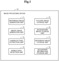
- FIG. 1 is a diagram for explaining a configuration of an image processing device
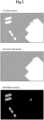
- Figs. 2 to 7 are diagrams for explaining the processing operation of the image processing device.
- An image processing device 10 of the present embodiment is for detecting a sea-going vessel in order to perform marine surveillance from captured images such as satellite images captured using a synthetic aperture radar (SAR).
- SAR synthetic aperture radar
- the image processing device 10 is configured of one or a plurality of information processing devices each having an arithmetic device and a storage device. As illustrated in Fig. 1 , the image processing device 10 includes a difference image generation unit 11, a binary image generation unit 12, a candidate pixel extraction unit 13, and a mobile body detection unit 14. The respective functions of the difference image generation unit 11, the binary image generation unit 12, the candidate pixel extraction unit 13, and the mobile body detection unit 14 can be implemented through execution, by the arithmetic unit, of a program for implementing the respective functions stored in the storage device.
- the image processing device 10 also includes a focused image storage unit 15, a background image storage unit 16, a difference image storage unit 17, and a geographic information storage unit 18.
- the focused image storage unit 15, the background image storage unit 16, the difference image storage unit 17, and the geographic information storage unit 18 are configured of a storage device.
- the respective constituent elements will be described in detail.
- the focused image storage unit 15 stores therein a focused image (object image) that is an image of a sea that is an area (object area) from which a vessel that is a mobile body is detected.
- a focused image is a satellite image captured using an SAR as illustrated in the upper drawing of Fig. 2 , and is mainly an image of the sea, but includes a land adjacent to the sea, or an object provided on the land.
- the luminance values of pixels in the focused image pixels of a land, an object on the land, and a vessel take high luminance values, and pixels of a water area that is sea take low luminance values. Since a focused image is a satellite image, it is associated with position information such as latitude and longitude on the earth based on information such as an orbit of the satellite and the setting of the imaging device.
- the background image storage unit 16 stores therein a background image that is a satellite image captured by using an SAR as similar to the focused image, and is an image of an area corresponding to the object area of the focused image, that is, the sea that is an area almost the same as the object area.
- a background image is a captured image at the time when there is no vessel moving in the object area such as the sea. Therefore, a background image is configured of an image captured in a time period when there is no vessel in the object area, or an image in which image processing of removing a mobile body, that is, a vessel, is performed on a plurality of past images of the object area.
- a background image is generated by performing positioning of a plurality of past captured images of the object area and selecting a minimum value for each pixel to thereby remove pixels of high luminance values that may be determined to be a vessel, as described below. Since a background image is a satellite image itself or generated from a satellite image, it is associated with position information such as latitude and longitude on the earth based on information such as an orbit of the satellite and the setting of the imaging device.
- the difference image storage unit 17 stores therein a difference image representing a difference between the focused image and the background image.
- a difference image is an image in which a difference between luminance values of pixels corresponding to each other in the focused image and the background image is generated as a new pixel value, as described below. Therefore, as illustrated in the lower drawing of Fig. 2 for example, in the difference image, a portion of the focused image having a change in the luminance value relative to the background image takes a high luminance value, so that a portion where a mobile body is not present in the background image but is present in the focused image is particularly represented by a high luminance value relative to the surroundings. Since a difference image is generated from a focused image and a background image that are satellite images, it is associated with position information such as latitude and longitude on the earth based on information such as an orbit of the satellite and the setting of the imaging device.
- the geographic information storage unit 18 stores therein map information of an object area where the focused image and the background image are captured.
- map information includes position information of a land of the object area, and includes position information such as latitude and longitude on the earth of the land, for example.
- the difference image generation unit 11 (image generation means) reads out, from the focused image storage unit 15, a focused image captured at a predetermined time that is a processing object from which a vessel is to be detected, reads out a background image from the background image storage unit 16, generates a difference image from the focused image and the background image, and stores it in the difference image storage unit 17.
- the difference image generation unit 11 performs positioning of the focused image illustrated in the upper drawing of Fig. 2 and the background image illustrated in the center drawing of Fig. 2 , on the basis of the position information, the similarity in the topography in the images, and the like, and calculates a difference between the luminance values of pixels corresponding to each other.
- the difference image generation unit 11 generates a difference image as illustrated in the lower drawing of Fig. 2 by using the difference as a new pixel value. Therefore, the generated difference image is an image in which a portion in the focused image where the luminance value has a change relative to the background image, that is, a portion of a mobile body in particular, is indicated by a higher luminance value relative to the surroundings.
- the difference image may be generated by a method other than that described above.
- the difference image generation unit 11 may have a function of generating a background image to be used for generating a difference image.
- the difference image generation unit 11 generates a background image by acquiring past captured images of the object area previously stored in the background image storage unit 16, performing positioning on those captured images on the basis of the position information, similarity of the topography in the images, and the like, and selecting a minimum value for each pixel to thereby remove pixels having high luminance values that may be determined as a vessel.
- a background image may be generated by any method.
- the binary image generation unit 12 (detection means) performs processing to binarize each of the focused image, the background image, and the difference image. At that time, the binary image generation unit 12 determines a threshold of a luminance value for binarization in each image. In the below description, a threshold setting process by the binary image generation unit 12 will be described first.
- the binary image generation unit 12 first uses the geographic information stored in the geographic information storage unit 18 to set a water area (specific area) on the focused image. Specifically, the binary image generation unit 12 specifies a land area (exclusion area) representing the position of the land on the focused image, from the position information included in the focused image and the geographic information including the position information of the land. Then, the binary image generation unit 12 sets an extended land area (extended exclusion area) that is obtained by extending the edge of the land adjacent to the water area in the land area by a predetermined distance to the water area side. For example, the binary image generation unit 12 sets the extended land area by extending the edge of the land area adjacent to the water area to the water area side by 20 pixels in the focused image, that is, by 20 m in the object area.
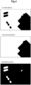
- the binary image generation unit 12 excludes the extended land area from the object area of the entire focused image and sets the remaining area as a water area. Thereby, the binary image generation unit 12 sets the water area on the focused image as indicated by an area surrounded by a dotted line in the upper drawing of Fig. 3 .
- the binary image generation unit 12 sets a water area on the background image as illustrated by an area surrounded by a dotted line in the center drawing of Fig. 3 , and sets a water area in the difference image as illustrated by an area surrounded by a dotted line in the lower drawing of Fig. 3 .
- a water area of a predetermined area located adjacent to the land is excluded as an extended land area. Therefore, it is possible to set a water area in which a bridge installed on a land or an object on the land such as a crane are excluded.
- the binary image generation unit 12 is not necessarily limited to set a water area by setting an extended land area as described above.
- the binary image generation unit 12 may set a water area by simply excluding the land area from the object area, or may set a water area by means of another method.
- the binary image generation unit 12 generates distribution of luminance values of pixels of a water area set in each of the focused image, the background image, and the difference image, and from the distribution, sets a threshold of luminance values for binarization. Specifically, for a focused image, the binary image generation unit 12 first generates distribution of luminance values of all pixels in the area set as a water area to be surrounded by a dotted line in the upper drawing of Fig. 3 . At that time, for example, the binary image generation unit 12 generates distribution of the luminance values of the pixels by approximating the distribution of the luminance values to a function. Then, from the generated distribution, the binary image generation unit 12 sets a threshold of luminance values for binarizing the focused image.
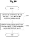
- the binary image generation unit 12 sets a threshold of luminance values with which luminance values of the sea that can be considered as a water area and luminance values that can be considered as an object existing in the water area are distinguishable from each other, in the water area in the focused image. Then, the binary image generation unit 12 uses the threshold set for the focused image to generate a binary image (transformed image) in which the luminance value of each pixel in the entire focused image is binarized. Thereby, the binary image generation unit 12 generates a binary image as illustrated in the upper drawing of Fig. 4 from the focused image.
- the binary image generation unit 12 also performs, on the background image and the difference image, the same processing as that performed on the focused image, and generates binary images respectively. Specifically, for the background image, the binary image generation unit 12 generates distribution of luminance values of all pixels in the area set as a water area surrounded by a dotted line in the center drawing of Fig. 3 , and from the distribution, sets a threshold of the luminance values for binarizing the background image, and generates a binary image as illustrated in the center drawing of Fig. 4 from the background image by using such a threshold.
- the binary image generation unit 12 sets a threshold of luminance values with which the luminance values of the sea that can be considered as a water area and the luminance values that can be considered as an object existing in the water area are distinguishable from each other, in the water area in the background image. Furthermore, for the difference image, the binary image generation unit 12 generates distribution of luminance values of all pixels in the area set as a water area surrounded by a dotted line in the lower drawing of Fig. 3 , and from the distribution, sets a threshold of the luminance values for binarizing the difference image, and generates a binary image as illustrated in the lower drawing of Fig. 4 from the difference image by using such a threshold.
- the binary image generation unit 12 sets a threshold of luminance values with which the luminance values of the sea that can be considered as a water area and the luminance values that can be considered as an object existing in the water area are distinguishable from each other, in the water area in the difference image.
- the binary image of the difference image becomes a binary image in which a pixel having a change in the luminance value and a pixel having no change in the luminance value between the focused image and the background image, that is, a pixel that can be considered as a water area and a pixel that can be considered as an object existing in the water area, are distinguishable from each other.
- the candidate pixel extraction unit 13 extracts a pixel of a candidate vessel by using the binary images of the focused image, the background image, and the difference image generated as described above. At that time, the candidate pixel extraction unit 13 determines, for each binary image, whether or not each pixel is a water area (specific area), and extracts a pixel that is a candidate vessel on the basis of the determination result of each binary image.
- the candidate pixel extraction unit 13 extracts it as a pixel of a candidate vessel.
- the pixels of the areas surrounded by the rectangles of the dotted lines in Fig. 5 are extracted as candidate vessels.
- the mobile body detection unit 14 detects a mobile body that is a vessel located on the focused image, on the basis of the pixels extracted as a candidate vessel as described above. For example, the mobile body detection unit 14 generates a figure configured of a plurality of pixels on the basis of the distance between the pixels extracted as a candidate vessel. For example, when the pixels extracted as a candidate vessel are adjacent to each other or located within a range of a certain distance, the mobile body detection unit 14 puts a set of the pixels into one figure. Then, the mobile body detection unit 14 compares, for example, the generated figure with a template indicating the shape of a vessel prepared in advance, and when determining that the generated figure is almost the same as the template, detects the generated figure as a vessel.
- the mobile body detection unit 14 detects that a while figure surrounded by a rectangle of a solid line as a vessel in the focused image.
- a plurality of determination criteria may be set for a set of pixels to be generated as one figure, depending on the vessel size.
- a plurality of past images of an object area captured in advance are stored in the background image storage unit 16, and a focused image in which an object area for detecting a vessel is captured is stored in the focused image storage unit 15.
- geographic information including position information of a land in the object area is stored in the geographic information storage unit 18.
- the image processing device 10 acquires a plurality of past captured images of an object area previously stored in the background image storage unit 16. Then, the image processing device 10 performs positioning on the captured images on the basis of the position information, selects a minimum value for each pixel to remove pixels having high luminance values that may be determined as a vessel to thereby generate a background image, and stores it in the background image storage unit 16 (step S1). For example, the image processing device 10 generates a background image as illustrated in the center drawing of Fig. 2 . Note that the process of generating a background image may not be performed, and may previously store an image determined that a mobile body such as a vessel is not present, as a background image.
- the image processing device 10 reads out, from the focused image storage unit 15, a focused image as illustrated in the upper drawing of Fig. 2 that is captured at a predetermined time and is an object of processing to detect a vessel, and also reads out a background image as illustrated in the center drawing of Fig. 2 from the background image storage unit 16. Then, the image processing device 10 calculates a difference between the luminance values of the pixels corresponding to each other from the focused image and the background image, generates a difference image by using the difference as a new pixel value, and stores it in the difference image storage unit 17 (step S2). For example, the image processing device 10 generates a difference image as illustrated in the lower drawing of Fig. 2 .
- the image processing device 10 sets a water area in each of the focused image, the background image, and the difference image (step S3).
- the image processing device 10 specifies a land area representing the position of the land on the focused image by using the geographic information stored in the geographic information storage unit 18, and sets an extended land area by extending the edge adjacent to the water area of the land area by a predetermined distance to the water area side.
- the image processing device 10 excludes the extended land area from the object area of the entire focused image, and sets the remaining area as a water area.
- the image processing device 10 sets the water area on the focused image as indicated by an area surrounded by the dotted line in the upper drawing of Fig. 3 for example.
- the image processing device 10 sets water areas on the background image and the difference image as indicated by the dotted line in the center drawing of Fig. 3 and the dotted line in the lower drawing of Fig. 3 , respectively.
- the image processing device 10 generates distribution of the luminance values of the pixels in the water area for each water area set in the focused image, the background image, and the difference image (step S4). For example, the image processing device 10 generates distribution of the luminance values of the pixels by approximating the distribution of the luminance values to a function. Then, from the distribution generated for each of the focused image, the background image, and the difference image, the image processing device 10 sets a threshold of a luminance value for binarizing each image (step S5).
- the image processing device 10 sets a threshold of luminance values with which the luminance values of the sea that can be considered as a water area and the luminance values that can be considered as an object existing in the water area are distinguishable from each other.
- the difference image it can be said to set a threshold of luminance values with which the pixels having no change and the pixels with a change between the focused image and the background image are distinguishable from each other.
- the image processing device 10 For each of the focused image, the background image, and the difference image, the image processing device 10 generates a binary image in which the luminance value of each pixel is binarized by using a threshold set for each image (step S6). As a result, the image processing device 10 generates binary images as illustrated in the upper drawing, the center drawing, and the lower drawing of Fig. 4 from the focused image, the background image, and the difference image, respectively.
- the image processing device 10 extracts a pixel that is a candidate vessel by using the binary images of the focused image, the background image, and the difference image generated as described above (step S7). For example, the image processing device 10 determines, for each binary image, whether or not each pixel is a water area, and extracts a pixel that is a candidate vessel on the basis of the determination result of each binary image.
- the image processing device 10 extracts it as a pixel of a candidate vessel.
- the pixels in the areas surrounded by the rectangles of dotted lines in Fig. 5 are extracted as candidate vessels.
- the image processing device 10 detects a mobile body that is a vessel located on the focused image, on the basis of the pixels extracted as a candidate vessel as described above (step S8).
- the image processing device 10 generates a figure configured of a plurality of pixels on the basis of a distance between the pixels extracted as a candidate vessel, and when the figure satisfies the criterion such as a template, the image processing device 10 detects it as a vessel.
- the image processing device 10 detects that a while figure surrounded by a rectangle of a solid line as a vessel in the focused image.
- a vessel can be detected with high accuracy by using binary images of an object image, a background image, and a difference image, performing binarization by using distribution of luminance values of a water area set to each of the object image, the background image, and the difference image, and setting a water area in which an expended land is removed at that time.
- the image processing device 10 detects a vessel appearing in the focused image.
- it is possible to detect various vessels by changing the criteria for extracting a pixel as a candidate vessel in the candidate pixel extraction unit 13.
- a vessel lost in the background image that is, a vessel that is at anchor in the background image but is lost in the focused image.
- the candidate pixel extraction unit 13 extracts it as a pixel of a candidate for a lost vessel.
- Figs. 8 and 9 are block diagrams illustrating a configuration of an image processing device according to the second exemplary embodiment
- Fig. 10 is a flowchart illustrating an operation of the image processing device. Note that the present embodiment shows the outlines of the configurations of the image processing device and the image processing method described in the embodiment described above.
- the image processing device 100 is configured of a typical information processing device, having a hardware configuration as described below as an example.
- the image processing device 100 can construct, and can be equipped with, an image generation means 121 and a detection means 122 illustrated in Fig. 9 through acquisition and execution of the program group 104 by the CPU 101.
- the program group 104 is stored in the storage device 105 or the ROM 102 in advance, and is loaded to the RAM 103 and executed by the CPU 101 as needed. Further, the program group 104 may be provided to the CPU 101 via the communication network 111, or may be stored on the storage medium 110 in advance and read out by the drive 106 and supplied to the CPU 101.
- the image generation means 121 and the detection means 122 may be constructed by dedicated electronic circuits for implementing such means.
- Fig. 8 illustrates an example of the hardware configuration of the information processing device that is the image processing device 100.
- the hardware configuration of the information processing device is not limited to that described above.
- the information processing device may be configured of part of the configuration described above, such as without the drive 106.
- the image processing device 100 executes the image processing method illustrated in the flowchart of Fig. 10 , by the functions of the image generation means 121 and the detection means 122 constructed by the program as described above.
- the image processing device 100 executes the processing to
- the present invention is configured as described above, by using an object image from which a mobile body is to be detected, a background image, and a difference image thereof, it is possible to detect a mobile body with high accuracy while suppressing an influence of an area that is different from the place to which the mobile body can move or an object existing in such an area.
- Non-transitory computer-readable media include tangible storage media of various types.
- Examples of non-transitory computer-readable media include magnetic storage media (for example, flexible disk, magnetic tape, and hard disk drive), magneto-optical storage media (for example, magneto-optical disk), a CD-ROM (Read Only Memory), a CD-R, a CD-R/W, and semiconductor memories (for example, mask ROM, PROM (Programmable ROM), EPROM (Erasable PROM), a flash ROM, and a RAM (Random Access Memory)).
- the program may be supplied to a computer by being stored in a transitory computer-readable medium of any type.
- transitory computer-readable media include electric signals, optical signals, and electromagnetic waves.
- a transitory computer-readable medium can be supplied to a computer via a wired communication channel such as a wire and an optical fiber, or a wireless communication channel.
- At least one of the functions of the image generation means 121 and the detection means 122 described above may be carried out by an information processing device provided and connected to any location on the network, that is, may be carried out by so-called cloud computing.
Landscapes
- Engineering & Computer Science (AREA)
- Physics & Mathematics (AREA)
- General Physics & Mathematics (AREA)
- Theoretical Computer Science (AREA)
- Remote Sensing (AREA)
- Multimedia (AREA)
- Radar, Positioning & Navigation (AREA)
- Computer Vision & Pattern Recognition (AREA)
- Electromagnetism (AREA)
- Computer Networks & Wireless Communication (AREA)
- Software Systems (AREA)
- Image Analysis (AREA)
- Image Processing (AREA)
Claims (3)
- Bildverarbeitungsvorrichtung, umfassend:eine Bilderzeugungseinrichtung (11) zum Erzeugen eines Differenzbildes, das eine Differenz zwischen einem Objektbild und einem Hintergrundbild darstellt, wobei das Objektbild ein Bild ist, das einen Zielbereich enthält, aus welchem ein mobiler Körper zu detektieren ist, wobei das Hintergrundbild den Zielbereich enthält und ein zu der Zeit erfasstes Bild ist, zu welcher es keinen mobilen Körper im Zielbereich gibt; undeine Detektionseinrichtung zum Detektieren des mobilen Körpers aus dem Objektbild auf der Basis des Objektbildes, des Hintergrundbildes und des Differenzbildes,wobei das Objektbild und das Hintergrundbild Satellitenbilder sind, die jeweils mit Positionsinformation assoziiert sind, die basierend auf einer Umlaufbahn eines Satelliten der Breitengrad und der Längengrad auf der Erde ist,wobei die Bilderzeugungseinrichtung (11) konfiguriert ist, um ein Positionieren des Objektbildes und des Hintergrundbildes auf der Basis der Positionsinformation und einer topologischen Ähnlichkeit zwischen dem Objektbild und dem Hintergrundbild durchzuführen, eine Differenz zwischen einem Luminanzwert jedes Pixels des Objektbildes und einem Luminanzwert eines entsprechenden Pixels des Hintergrundbildes zu berechnen und das Differenzbild unter Verwendung der berechneten Differenzen als Pixelwerte zu erzeugen, undwobei die Detektionseinrichtung folgendes umfasst:eine Binärbilderzeugungseinrichtung (12), die konfiguriert ist, umauf der Basis von in jedem des Objektbildes, des Hintergrundbildes und des Differenzbildes enthaltener Positionsinformation und geografischer Information, die Positionsinformation von einem Land enthält, einen Sperrbereich zu spezifizieren, der ein Landbereich ist, der eine Position des Landes auf jedem des Objektbildes, des Hintergrundbildes und des Differenzbildes darstellt,einen erweiterten Sperrbereich einzustellen, der durch Erweitern des spezifizierten Sperrbereichs gemäß einem vorbestimmten Kriterium aus dem in jedem des Objektbildes, des Hintergrundbildes und des Differenzbildes enthaltenen Zielbereich erzeugt ist,einen restlichen Bereich, in welchem der erweiterte Sperrbereich aus dem in jedem des Objektbildes, des Hintergrundbildes und des Differenzbildes enthaltenen Zielbereich entfernt ist, derart zu bestimmen, dass er ein Wasserbereich ist,eine Verteilung von Luminanzwerten von Pixeln in dem in jedem des Objektbildes, des Hintergrundbildes und des Differenzbildes enthaltenen Wasserbereich zu erzeugen,eine Schwelle von Luminanzwerten, mit welcher Luminanzwerte, die als Wasserbereich angesehen werden können, und Luminanzwerte, die als im Wasserbereich existierendes Objekt angesehen werden können, voneinander unterscheidbar sind, im Wasserbereich in jedem des Objektbildes, des Hintergrundbildes und des Differenzbildes einzustellen, unddurch Binarisieren des Objektbildes, des Hintergrundbildes und des Differenzbildes jeweils mit einem Verwenden der eingestellten Schwellen erhaltene Binärbilder zu erzeugen;eine Kandidatenpixel-Extraktionseinheit (13), die konfiguriert ist, umauf der Basis der Binärbilder des Objektbildes, des Hintergrundbildes und des Differenzbildes Pixel zu detektieren, die jeweils erfüllen, dass das Pixel nicht ein Wasserbereich im Binärbild des Objektbildes ist, das Pixel ein Wasserbereich im Binärbild des Hintergrundbildes ist und das Pixel nicht ein Wasserbereich im Binärbild des Differenzbildes ist, unddie detektierten Pixel als Pixel eines Kandidaten eines mobilen Körpers zu extrahieren; undeine Detektionseinrichtung für einen mobilen Körper (14), die konfiguriert ist, um den mobilen Körper im Objektbild auf der Basis der extrahierten Pixel zu detektieren.
- Computerimplementiertes Bildverarbeitungsverfahren, umfassend:(S2) Erzeugen eines Differenzbildes, das eine Differenz zwischen einem Objektbild und einem Hintergrundbild darstellt, wobei das Objektbild ein Bild ist, das einen Zielbereich enthält, aus welchem ein mobiler Körper zu detektieren ist, wobei das Hintergrundbild den Zielbereich enthält und ein zu der Zeit erfasstes Bild ist, zu welcher es keinen mobilen Körper im Zielbereich gibt; undDetektieren des mobilen Körpers aus dem Objektbild auf der Basis des Objektbildes, des Hintergrundbildes und des Differenzbildes,wobei das Objektbild und das Hintergrundbild Satellitenbilder sind, die jeweils mit Positionsinformation assoziiert sind, die der Breitengrad und der Längengrad auf der Erde ist,wobei das Erzeugen folgendes umfasst:Durchführen eines Positionierens des Objektbildes und des Hintergrundbildes auf der Basis der Positionsinformation oder einer topologischen Ähnlichkeit zwischen dem Objektbild und dem Hintergrundbild,Berechnen einer Differenz zwischen einem Luminanzwert jedes Pixels des Objektbildes und einem Luminanzwert eines entsprechenden Pixels des Hintergrundbildes, undErzeugen des Differenzbildes unter Verwendung der berechneten Differenzen als Pixelwerte, undwobei das Detektieren folgendes umfasst:(S3) auf der Basis von in jedem des Objektbildes, des Hintergrundbildes und des Differenzbildes enthaltener Positionsinformation und geografischer Information, die Positionsinformation von einem Land enthält, Spezifizieren eines Sperrbereichs, der ein Landbereich ist, der eine Position des Landes auf jedem des Objektbildes, des Hintergrundbildes und des Differenzbildes darstellt,(S3) Einstellen eines erweiterten Sperrbereichs, der durch Erweitern des spezifizierten Sperrbereichs gemäß einem vorbestimmten Kriterium aus dem in jedem des Objektbildes, des Hintergrundbildes und des Differenzbildes enthaltenen Zielbereich erzeugt ist,(S3) derartiges Bestimmen eines restlichen Bereichs, in welchem der erweiterte Sperrbereich aus dem in jedem des Objektbildes, des Hintergrundbildes und des Differenzbildes enthaltenen Zielbereich entfernt ist, dass er ein Wasserbereich ist,(S4) Erzeugen einer Verteilung von Luminanzwerten von Pixeln in dem in jedem des Objektbildes, des Hintergrundbildes und des Differenzbildes enthaltenen Wasserbereich,(S5) Einstellen einer Schwelle von Luminanzwerten, mit welcher Luminanzwerte, die als Wasserbereich angesehen werden können, und Luminanzwerte, die als im Wasserbereich existierendes Objekt angesehen werden können, voneinander unterscheidbar sind, im Wasserbereich in jedem des Objektbildes, des Hintergrundbildes und des Differenzbildes, und(S6) Erzeugen von durch Binarisieren des Objektbildes, des Hintergrundbildes und des Differenzbildes jeweils mit einem Verwenden der eingestellten Schwellen erhaltenen Binärbildern;(S7) auf der Basis der Binärbilder des Objektbildes, des Hintergrundbildes und des Differenzbildes Detektieren von Pixeln, die jeweils erfüllen, dass das Pixel nicht ein Wasserbereich im Binärbild des Objektbildes ist, das Pixel ein Wasserbereich im Binärbild des Hintergrundbildes ist und das Pixel nicht ein Wasserbereich im Binärbild des Differenzbildes ist, und(S7) Extrahieren der detektierten Pixel als Pixel eines Kandidaten eines mobilen Körpers; und(S8) Detektieren des mobilen Körper im Objektbild auf der Basis der extrahierten Pixel.
- Programm zum Veranlassen, dass ein Computer das Verfahren nach Anspruch 2 durchführt.
Applications Claiming Priority (1)
| Application Number | Priority Date | Filing Date | Title |
|---|---|---|---|
| PCT/JP2020/016962 WO2021210181A1 (ja) | 2020-04-17 | 2020-04-17 | 画像処理方法 |
Publications (3)
| Publication Number | Publication Date |
|---|---|
| EP4138031A1 EP4138031A1 (de) | 2023-02-22 |
| EP4138031A4 EP4138031A4 (de) | 2023-06-14 |
| EP4138031B1 true EP4138031B1 (de) | 2024-06-05 |
Family
ID=78084761
Family Applications (1)
| Application Number | Title | Priority Date | Filing Date |
|---|---|---|---|
| EP20931455.8A Active EP4138031B1 (de) | 2020-04-17 | 2020-04-17 | Bildverarbeitungsverfahren |
Country Status (4)
| Country | Link |
|---|---|
| US (1) | US20230133519A1 (de) |
| EP (1) | EP4138031B1 (de) |
| JP (1) | JP7509197B2 (de) |
| WO (1) | WO2021210181A1 (de) |
Families Citing this family (1)
| Publication number | Priority date | Publication date | Assignee | Title |
|---|---|---|---|---|
| CN118097551B (zh) * | 2024-02-29 | 2024-08-16 | 上海天齐智能建筑股份有限公司 | 一种基于机器视觉的安防监控系统及方法 |
Family Cites Families (11)
| Publication number | Priority date | Publication date | Assignee | Title |
|---|---|---|---|---|
| JPH09288732A (ja) * | 1996-04-23 | 1997-11-04 | Mitsubishi Heavy Ind Ltd | 航行船舶認識装置 |
| JP3850602B2 (ja) * | 1999-10-18 | 2006-11-29 | 三菱電機株式会社 | 移動体検出装置および移動体検出方法 |
| JP4032800B2 (ja) * | 2002-04-11 | 2008-01-16 | 株式会社日立製作所 | 地図解析装置及びその実現のためのプログラム |
| JP2004227527A (ja) * | 2003-01-27 | 2004-08-12 | Fujitsu Ltd | 画像処理方法、その方法をコンピュータに行わせるプログラム、そのプログラムを記録する記録媒体 |
| JP5891022B2 (ja) * | 2011-12-06 | 2016-03-22 | ハンファテクウィン株式会社Hanwha Techwin Co.,Ltd. | 物体検出装置、監視カメラ、及び物体検出方法 |
| US9192348B2 (en) * | 2014-01-23 | 2015-11-24 | Perkinelmer Cellular Technologies Germany Gmbh | Method and system for automated detection of tissue interior to a mammalian ribcage from an in vivo image |
| CN106651880B (zh) * | 2016-12-27 | 2020-04-14 | 首都师范大学 | 基于多特征融合的热红外遥感影像的海上动目标检测方法 |
| CN107563985B (zh) * | 2017-08-31 | 2020-08-25 | 成都空御科技有限公司 | 一种红外图像空中运动目标的检测方法 |
| CN108230364B (zh) * | 2018-01-12 | 2022-02-11 | 东南大学 | 一种基于神经网络的前景物体运动状态分析方法 |
| JP6991089B2 (ja) | 2018-03-28 | 2022-01-12 | 株式会社Ihi | 船舶検出装置及び方法 |
| CN110751643A (zh) * | 2019-10-21 | 2020-02-04 | 睿视智觉(厦门)科技有限公司 | 一种水质异常检测方法、装置及设备 |
-
2020
- 2020-04-17 US US17/918,156 patent/US20230133519A1/en not_active Abandoned
- 2020-04-17 JP JP2022515180A patent/JP7509197B2/ja active Active
- 2020-04-17 EP EP20931455.8A patent/EP4138031B1/de active Active
- 2020-04-17 WO PCT/JP2020/016962 patent/WO2021210181A1/ja not_active Ceased
Also Published As
| Publication number | Publication date |
|---|---|
| EP4138031A4 (de) | 2023-06-14 |
| EP4138031A1 (de) | 2023-02-22 |
| WO2021210181A1 (ja) | 2021-10-21 |
| US20230133519A1 (en) | 2023-05-04 |
| JP7509197B2 (ja) | 2024-07-02 |
| JPWO2021210181A1 (de) | 2021-10-21 |
Similar Documents
| Publication | Publication Date | Title |
|---|---|---|
| JP6977873B2 (ja) | 画像処理装置、画像処理方法、及び、画像処理プログラム | |
| JP6319785B2 (ja) | 異常潮位変動検知装置、異常潮位変動検知方法、及び異常潮位変動検知プログラム | |
| US10977923B2 (en) | River risk level determining device, river risk level determining method, and storage medium | |
| JP7184101B2 (ja) | 船舶行動解析装置、船舶行動解析方法及びプログラム | |
| JP6632474B2 (ja) | 監視装置、監視方法及び空港監視システム | |
| US20210132214A1 (en) | Synthetic aperture radar image analysis system, synthetic aperture radar image analysis method, and synthetic aperture radar image analysis program | |
| US20240303852A1 (en) | Methods and systems for detecting vessels | |
| CN112686106B (zh) | 一种视频图像转海事雷达图像的方法 | |
| KR20180020421A (ko) | 대용량 고해상도 위성 영상을 이용한 해안선 추출 방법 및 시스템 | |
| US20230133519A1 (en) | Image processing method | |
| WO2022247684A1 (zh) | 基站馈线检测方法、系统及相关装置 | |
| JP2016053763A (ja) | 画像処理装置、画像処理方法及びプログラム | |
| US12597222B2 (en) | Method and system for determining a region of water clearance of a water surface | |
| US20230360361A1 (en) | Image processing method | |
| GB2523598A (en) | Method for determining the position of a client device | |
| CN120807604B (zh) | 深度估计模型训练方法、深度图估计方法及相关装置 | |
| CN119850665B (zh) | 空间目标边缘检测方法、装置、设备和介质 | |
| CN116778340B (zh) | 兼顾全局和局部信息感知的雷达图像舰船目标检测方法 | |
| EP4181087B1 (de) | Sichtbarkeitsbestimmungssystem, sichtbarkeitsbestimmungsverfahren und programm | |
| KR102695156B1 (ko) | 컨테이너 선박 자동 탐지 시스템 및 그 방법 | |
| JP2025166872A (ja) | 画像処理装置、画像処理方法及び画像処理プログラム | |
| Xu et al. | On-borne automated detection of ocean internal waves in SAR images based on spatial features | |
| KR20250118812A (ko) | Ai를 기반으로 한 건물의 3d 모델링 데이터 자동 생성 방법 | |
| CN122066818A (en) | Grid map processing method, related device and computer program product | |
| CN121982556A (zh) | 一种基于深度学习的光学卫星影像舰船检测与航向判断方法 |
Legal Events
| Date | Code | Title | Description |
|---|---|---|---|
| STAA | Information on the status of an ep patent application or granted ep patent |
Free format text: STATUS: THE INTERNATIONAL PUBLICATION HAS BEEN MADE |
|
| PUAI | Public reference made under article 153(3) epc to a published international application that has entered the european phase |
Free format text: ORIGINAL CODE: 0009012 |
|
| STAA | Information on the status of an ep patent application or granted ep patent |
Free format text: STATUS: REQUEST FOR EXAMINATION WAS MADE |
|
| 17P | Request for examination filed |
Effective date: 20221107 |
|
| AK | Designated contracting states |
Kind code of ref document: A1 Designated state(s): AL AT BE BG CH CY CZ DE DK EE ES FI FR GB GR HR HU IE IS IT LI LT LU LV MC MK MT NL NO PL PT RO RS SE SI SK SM TR |
|
| A4 | Supplementary search report drawn up and despatched |
Effective date: 20230515 |
|
| RIC1 | Information provided on ipc code assigned before grant |
Ipc: G06V 20/40 20220101ALI20230509BHEP Ipc: G06T 7/136 20170101ALI20230509BHEP Ipc: G06T 7/254 20170101ALI20230509BHEP Ipc: G06T 7/00 20170101AFI20230509BHEP |
|
| DAV | Request for validation of the european patent (deleted) | ||
| DAX | Request for extension of the european patent (deleted) | ||
| GRAP | Despatch of communication of intention to grant a patent |
Free format text: ORIGINAL CODE: EPIDOSNIGR1 |
|
| STAA | Information on the status of an ep patent application or granted ep patent |
Free format text: STATUS: GRANT OF PATENT IS INTENDED |
|
| INTG | Intention to grant announced |
Effective date: 20240209 |
|
| GRAS | Grant fee paid |
Free format text: ORIGINAL CODE: EPIDOSNIGR3 |
|
| GRAA | (expected) grant |
Free format text: ORIGINAL CODE: 0009210 |
|
| STAA | Information on the status of an ep patent application or granted ep patent |
Free format text: STATUS: THE PATENT HAS BEEN GRANTED |
|
| AK | Designated contracting states |
Kind code of ref document: B1 Designated state(s): AL AT BE BG CH CY CZ DE DK EE ES FI FR GB GR HR HU IE IS IT LI LT LU LV MC MK MT NL NO PL PT RO RS SE SI SK SM TR |
|
| REG | Reference to a national code |
Ref country code: CH Ref legal event code: EP |
|
| REG | Reference to a national code |
Ref country code: DE Ref legal event code: R096 Ref document number: 602020032151 Country of ref document: DE |
|
| REG | Reference to a national code |
Ref country code: IE Ref legal event code: FG4D |
|
| REG | Reference to a national code |
Ref country code: LT Ref legal event code: MG9D |
|
| PG25 | Lapsed in a contracting state [announced via postgrant information from national office to epo] |
Ref country code: BG Free format text: LAPSE BECAUSE OF FAILURE TO SUBMIT A TRANSLATION OF THE DESCRIPTION OR TO PAY THE FEE WITHIN THE PRESCRIBED TIME-LIMIT Effective date: 20240605 |
|
| REG | Reference to a national code |
Ref country code: NL Ref legal event code: MP Effective date: 20240605 |
|
| PG25 | Lapsed in a contracting state [announced via postgrant information from national office to epo] |
Ref country code: HR Free format text: LAPSE BECAUSE OF FAILURE TO SUBMIT A TRANSLATION OF THE DESCRIPTION OR TO PAY THE FEE WITHIN THE PRESCRIBED TIME-LIMIT Effective date: 20240605 Ref country code: FI Free format text: LAPSE BECAUSE OF FAILURE TO SUBMIT A TRANSLATION OF THE DESCRIPTION OR TO PAY THE FEE WITHIN THE PRESCRIBED TIME-LIMIT Effective date: 20240605 |
|
| PG25 | Lapsed in a contracting state [announced via postgrant information from national office to epo] |
Ref country code: GR Free format text: LAPSE BECAUSE OF FAILURE TO SUBMIT A TRANSLATION OF THE DESCRIPTION OR TO PAY THE FEE WITHIN THE PRESCRIBED TIME-LIMIT Effective date: 20240906 |
|
| PG25 | Lapsed in a contracting state [announced via postgrant information from national office to epo] |
Ref country code: ES Free format text: LAPSE BECAUSE OF FAILURE TO SUBMIT A TRANSLATION OF THE DESCRIPTION OR TO PAY THE FEE WITHIN THE PRESCRIBED TIME-LIMIT Effective date: 20240605 |
|
| PG25 | Lapsed in a contracting state [announced via postgrant information from national office to epo] |
Ref country code: LV Free format text: LAPSE BECAUSE OF FAILURE TO SUBMIT A TRANSLATION OF THE DESCRIPTION OR TO PAY THE FEE WITHIN THE PRESCRIBED TIME-LIMIT Effective date: 20240605 |
|
| PG25 | Lapsed in a contracting state [announced via postgrant information from national office to epo] |
Ref country code: NO Free format text: LAPSE BECAUSE OF FAILURE TO SUBMIT A TRANSLATION OF THE DESCRIPTION OR TO PAY THE FEE WITHIN THE PRESCRIBED TIME-LIMIT Effective date: 20240905 Ref country code: LV Free format text: LAPSE BECAUSE OF FAILURE TO SUBMIT A TRANSLATION OF THE DESCRIPTION OR TO PAY THE FEE WITHIN THE PRESCRIBED TIME-LIMIT Effective date: 20240605 Ref country code: HR Free format text: LAPSE BECAUSE OF FAILURE TO SUBMIT A TRANSLATION OF THE DESCRIPTION OR TO PAY THE FEE WITHIN THE PRESCRIBED TIME-LIMIT Effective date: 20240605 Ref country code: GR Free format text: LAPSE BECAUSE OF FAILURE TO SUBMIT A TRANSLATION OF THE DESCRIPTION OR TO PAY THE FEE WITHIN THE PRESCRIBED TIME-LIMIT Effective date: 20240906 Ref country code: FI Free format text: LAPSE BECAUSE OF FAILURE TO SUBMIT A TRANSLATION OF THE DESCRIPTION OR TO PAY THE FEE WITHIN THE PRESCRIBED TIME-LIMIT Effective date: 20240605 Ref country code: ES Free format text: LAPSE BECAUSE OF FAILURE TO SUBMIT A TRANSLATION OF THE DESCRIPTION OR TO PAY THE FEE WITHIN THE PRESCRIBED TIME-LIMIT Effective date: 20240605 Ref country code: BG Free format text: LAPSE BECAUSE OF FAILURE TO SUBMIT A TRANSLATION OF THE DESCRIPTION OR TO PAY THE FEE WITHIN THE PRESCRIBED TIME-LIMIT Effective date: 20240605 Ref country code: RS Free format text: LAPSE BECAUSE OF FAILURE TO SUBMIT A TRANSLATION OF THE DESCRIPTION OR TO PAY THE FEE WITHIN THE PRESCRIBED TIME-LIMIT Effective date: 20240905 |
|
| PG25 | Lapsed in a contracting state [announced via postgrant information from national office to epo] |
Ref country code: NL Free format text: LAPSE BECAUSE OF FAILURE TO SUBMIT A TRANSLATION OF THE DESCRIPTION OR TO PAY THE FEE WITHIN THE PRESCRIBED TIME-LIMIT Effective date: 20240605 |
|
| REG | Reference to a national code |
Ref country code: AT Ref legal event code: MK05 Ref document number: 1693012 Country of ref document: AT Kind code of ref document: T Effective date: 20240605 |
|
| PG25 | Lapsed in a contracting state [announced via postgrant information from national office to epo] |
Ref country code: NL Free format text: LAPSE BECAUSE OF FAILURE TO SUBMIT A TRANSLATION OF THE DESCRIPTION OR TO PAY THE FEE WITHIN THE PRESCRIBED TIME-LIMIT Effective date: 20240605 |
|
| PG25 | Lapsed in a contracting state [announced via postgrant information from national office to epo] |
Ref country code: PT Free format text: LAPSE BECAUSE OF FAILURE TO SUBMIT A TRANSLATION OF THE DESCRIPTION OR TO PAY THE FEE WITHIN THE PRESCRIBED TIME-LIMIT Effective date: 20241007 |
|
| PG25 | Lapsed in a contracting state [announced via postgrant information from national office to epo] |
Ref country code: PT Free format text: LAPSE BECAUSE OF FAILURE TO SUBMIT A TRANSLATION OF THE DESCRIPTION OR TO PAY THE FEE WITHIN THE PRESCRIBED TIME-LIMIT Effective date: 20241007 |
|
| PG25 | Lapsed in a contracting state [announced via postgrant information from national office to epo] |
Ref country code: PL Free format text: LAPSE BECAUSE OF FAILURE TO SUBMIT A TRANSLATION OF THE DESCRIPTION OR TO PAY THE FEE WITHIN THE PRESCRIBED TIME-LIMIT Effective date: 20240605 |
|
| PG25 | Lapsed in a contracting state [announced via postgrant information from national office to epo] |
Ref country code: EE Free format text: LAPSE BECAUSE OF FAILURE TO SUBMIT A TRANSLATION OF THE DESCRIPTION OR TO PAY THE FEE WITHIN THE PRESCRIBED TIME-LIMIT Effective date: 20240605 |
|
| PG25 | Lapsed in a contracting state [announced via postgrant information from national office to epo] |
Ref country code: AT Free format text: LAPSE BECAUSE OF FAILURE TO SUBMIT A TRANSLATION OF THE DESCRIPTION OR TO PAY THE FEE WITHIN THE PRESCRIBED TIME-LIMIT Effective date: 20240605 Ref country code: IS Free format text: LAPSE BECAUSE OF FAILURE TO SUBMIT A TRANSLATION OF THE DESCRIPTION OR TO PAY THE FEE WITHIN THE PRESCRIBED TIME-LIMIT Effective date: 20241005 |
|
| PG25 | Lapsed in a contracting state [announced via postgrant information from national office to epo] |
Ref country code: CZ Free format text: LAPSE BECAUSE OF FAILURE TO SUBMIT A TRANSLATION OF THE DESCRIPTION OR TO PAY THE FEE WITHIN THE PRESCRIBED TIME-LIMIT Effective date: 20240605 |
|
| PG25 | Lapsed in a contracting state [announced via postgrant information from national office to epo] |
Ref country code: RO Free format text: LAPSE BECAUSE OF FAILURE TO SUBMIT A TRANSLATION OF THE DESCRIPTION OR TO PAY THE FEE WITHIN THE PRESCRIBED TIME-LIMIT Effective date: 20240605 Ref country code: SK Free format text: LAPSE BECAUSE OF FAILURE TO SUBMIT A TRANSLATION OF THE DESCRIPTION OR TO PAY THE FEE WITHIN THE PRESCRIBED TIME-LIMIT Effective date: 20240605 |
|
| PG25 | Lapsed in a contracting state [announced via postgrant information from national office to epo] |
Ref country code: SM Free format text: LAPSE BECAUSE OF FAILURE TO SUBMIT A TRANSLATION OF THE DESCRIPTION OR TO PAY THE FEE WITHIN THE PRESCRIBED TIME-LIMIT Effective date: 20240605 |
|
| PG25 | Lapsed in a contracting state [announced via postgrant information from national office to epo] |
Ref country code: SM Free format text: LAPSE BECAUSE OF FAILURE TO SUBMIT A TRANSLATION OF THE DESCRIPTION OR TO PAY THE FEE WITHIN THE PRESCRIBED TIME-LIMIT Effective date: 20240605 Ref country code: SK Free format text: LAPSE BECAUSE OF FAILURE TO SUBMIT A TRANSLATION OF THE DESCRIPTION OR TO PAY THE FEE WITHIN THE PRESCRIBED TIME-LIMIT Effective date: 20240605 Ref country code: RO Free format text: LAPSE BECAUSE OF FAILURE TO SUBMIT A TRANSLATION OF THE DESCRIPTION OR TO PAY THE FEE WITHIN THE PRESCRIBED TIME-LIMIT Effective date: 20240605 Ref country code: PL Free format text: LAPSE BECAUSE OF FAILURE TO SUBMIT A TRANSLATION OF THE DESCRIPTION OR TO PAY THE FEE WITHIN THE PRESCRIBED TIME-LIMIT Effective date: 20240605 Ref country code: IS Free format text: LAPSE BECAUSE OF FAILURE TO SUBMIT A TRANSLATION OF THE DESCRIPTION OR TO PAY THE FEE WITHIN THE PRESCRIBED TIME-LIMIT Effective date: 20241005 Ref country code: EE Free format text: LAPSE BECAUSE OF FAILURE TO SUBMIT A TRANSLATION OF THE DESCRIPTION OR TO PAY THE FEE WITHIN THE PRESCRIBED TIME-LIMIT Effective date: 20240605 Ref country code: CZ Free format text: LAPSE BECAUSE OF FAILURE TO SUBMIT A TRANSLATION OF THE DESCRIPTION OR TO PAY THE FEE WITHIN THE PRESCRIBED TIME-LIMIT Effective date: 20240605 Ref country code: AT Free format text: LAPSE BECAUSE OF FAILURE TO SUBMIT A TRANSLATION OF THE DESCRIPTION OR TO PAY THE FEE WITHIN THE PRESCRIBED TIME-LIMIT Effective date: 20240605 |
|
| PG25 | Lapsed in a contracting state [announced via postgrant information from national office to epo] |
Ref country code: IT Free format text: LAPSE BECAUSE OF FAILURE TO SUBMIT A TRANSLATION OF THE DESCRIPTION OR TO PAY THE FEE WITHIN THE PRESCRIBED TIME-LIMIT Effective date: 20240605 |
|
| REG | Reference to a national code |
Ref country code: DE Ref legal event code: R097 Ref document number: 602020032151 Country of ref document: DE |
|
| PLBE | No opposition filed within time limit |
Free format text: ORIGINAL CODE: 0009261 |
|
| STAA | Information on the status of an ep patent application or granted ep patent |
Free format text: STATUS: NO OPPOSITION FILED WITHIN TIME LIMIT |
|
| PG25 | Lapsed in a contracting state [announced via postgrant information from national office to epo] |
Ref country code: DK Free format text: LAPSE BECAUSE OF FAILURE TO SUBMIT A TRANSLATION OF THE DESCRIPTION OR TO PAY THE FEE WITHIN THE PRESCRIBED TIME-LIMIT Effective date: 20240605 |
|
| 26N | No opposition filed |
Effective date: 20250306 |
|
| PGFP | Annual fee paid to national office [announced via postgrant information from national office to epo] |
Ref country code: DE Payment date: 20250422 Year of fee payment: 6 |
|
| PGFP | Annual fee paid to national office [announced via postgrant information from national office to epo] |
Ref country code: GB Payment date: 20250423 Year of fee payment: 6 |
|
| PG25 | Lapsed in a contracting state [announced via postgrant information from national office to epo] |
Ref country code: SE Free format text: LAPSE BECAUSE OF FAILURE TO SUBMIT A TRANSLATION OF THE DESCRIPTION OR TO PAY THE FEE WITHIN THE PRESCRIBED TIME-LIMIT Effective date: 20240605 |
|
| REG | Reference to a national code |
Ref country code: CH Ref legal event code: H13 Free format text: ST27 STATUS EVENT CODE: U-0-0-H10-H13 (AS PROVIDED BY THE NATIONAL OFFICE) Effective date: 20251125 |
|
| PG25 | Lapsed in a contracting state [announced via postgrant information from national office to epo] |
Ref country code: LU Free format text: LAPSE BECAUSE OF NON-PAYMENT OF DUE FEES Effective date: 20250417 |
|
| PG25 | Lapsed in a contracting state [announced via postgrant information from national office to epo] |
Ref country code: MC Free format text: LAPSE BECAUSE OF FAILURE TO SUBMIT A TRANSLATION OF THE DESCRIPTION OR TO PAY THE FEE WITHIN THE PRESCRIBED TIME-LIMIT Effective date: 20240605 |
|
| REG | Reference to a national code |
Ref country code: BE Ref legal event code: MM Effective date: 20250430 |
|
| PG25 | Lapsed in a contracting state [announced via postgrant information from national office to epo] |
Ref country code: FR Free format text: LAPSE BECAUSE OF NON-PAYMENT OF DUE FEES Effective date: 20250430 |
|
| PG25 | Lapsed in a contracting state [announced via postgrant information from national office to epo] |
Ref country code: BE Free format text: LAPSE BECAUSE OF NON-PAYMENT OF DUE FEES Effective date: 20250430 |
|
| PG25 | Lapsed in a contracting state [announced via postgrant information from national office to epo] |
Ref country code: CH Free format text: LAPSE BECAUSE OF NON-PAYMENT OF DUE FEES Effective date: 20250430 |
|
| PG25 | Lapsed in a contracting state [announced via postgrant information from national office to epo] |
Ref country code: IE Free format text: LAPSE BECAUSE OF NON-PAYMENT OF DUE FEES Effective date: 20250417 |