EP4137833A1 - Matratze für einen untersuchungstisch eines mrt-geräts mit einem kabelkanal - Google Patents
Matratze für einen untersuchungstisch eines mrt-geräts mit einem kabelkanal Download PDFInfo
- Publication number
- EP4137833A1 EP4137833A1 EP21198791.2A EP21198791A EP4137833A1 EP 4137833 A1 EP4137833 A1 EP 4137833A1 EP 21198791 A EP21198791 A EP 21198791A EP 4137833 A1 EP4137833 A1 EP 4137833A1
- Authority
- EP
- European Patent Office
- Prior art keywords
- mattress
- cable
- wall
- cable duct
- slit
- Prior art date
- Legal status (The legal status is an assumption and is not a legal conclusion. Google has not performed a legal analysis and makes no representation as to the accuracy of the status listed.)
- Withdrawn
Links
- 239000000463 material Substances 0.000 claims description 20
- 238000000034 method Methods 0.000 claims description 4
- 239000006261 foam material Substances 0.000 description 4
- 238000007726 management method Methods 0.000 description 4
- DQXBYHZEEUGOBF-UHFFFAOYSA-N but-3-enoic acid;ethene Chemical compound C=C.OC(=O)CC=C DQXBYHZEEUGOBF-UHFFFAOYSA-N 0.000 description 2
- 230000001419 dependent effect Effects 0.000 description 2
- 239000005038 ethylene vinyl acetate Substances 0.000 description 2
- 229920001200 poly(ethylene-vinyl acetate) Polymers 0.000 description 2
- 239000004814 polyurethane Substances 0.000 description 2
- 125000006850 spacer group Chemical group 0.000 description 2
- 239000006260 foam Substances 0.000 description 1
- 238000002595 magnetic resonance imaging Methods 0.000 description 1
- 229920002635 polyurethane Polymers 0.000 description 1
Images



Classifications
-
- A—HUMAN NECESSITIES
- A61—MEDICAL OR VETERINARY SCIENCE; HYGIENE
- A61B—DIAGNOSIS; SURGERY; IDENTIFICATION
- A61B8/00—Diagnosis using ultrasonic, sonic or infrasonic waves
- A61B8/08—Clinical applications
- A61B8/0858—Clinical applications involving measuring tissue layers, e.g. skin, interfaces
-
- A—HUMAN NECESSITIES
- A61—MEDICAL OR VETERINARY SCIENCE; HYGIENE
- A61B—DIAGNOSIS; SURGERY; IDENTIFICATION
- A61B8/00—Diagnosis using ultrasonic, sonic or infrasonic waves
- A61B8/46—Ultrasonic, sonic or infrasonic diagnostic devices with special arrangements for interfacing with the operator or the patient
- A61B8/467—Ultrasonic, sonic or infrasonic diagnostic devices with special arrangements for interfacing with the operator or the patient characterised by special input means
- A61B8/469—Ultrasonic, sonic or infrasonic diagnostic devices with special arrangements for interfacing with the operator or the patient characterised by special input means for selection of a region of interest
-
- A—HUMAN NECESSITIES
- A61—MEDICAL OR VETERINARY SCIENCE; HYGIENE
- A61B—DIAGNOSIS; SURGERY; IDENTIFICATION
- A61B8/00—Diagnosis using ultrasonic, sonic or infrasonic waves
- A61B8/52—Devices using data or image processing specially adapted for diagnosis using ultrasonic, sonic or infrasonic waves
- A61B8/5215—Devices using data or image processing specially adapted for diagnosis using ultrasonic, sonic or infrasonic waves involving processing of medical diagnostic data
- A61B8/5223—Devices using data or image processing specially adapted for diagnosis using ultrasonic, sonic or infrasonic waves involving processing of medical diagnostic data for extracting a diagnostic or physiological parameter from medical diagnostic data
Definitions
- the invention relates to the field of mattresses, and in particular to mattresses for supporting patients under examination, especially in a magnetic resonance (MR) apparatus.
- MR magnetic resonance
- balun which becomes hot during the MR scan.
- Managing the cables, especially those with balun, on such an examination table of a MR system is difficult and annoying, especially for the following problems. Due to the lack of proper cable management method, the coil cables with balun have to be placed on the body of the person who is under examination. This leads to a risk of balun burning of the person. To mitigate the risk of burning, typically, an additional spacer is required to be placed between the balun and the person. Further, the coil setup gets even more complicated when more coils are necessary for examination. In addition, there is a risk that the cables and baluns fall off from the examination table. Furthermore, the person's comfort is highly restricted due to the many items, including baluns, cables, and the spacer, which are arranged on the person's body.
- a bed apparatus for a magnetic resonance imaging apparatus which includes a table, a table driving mechanism, a bed supporting part, and a cable guide.
- the table provides a connection port for a reception coil of magnetic resonance signals.
- the table driving mechanism is configured to shift the table.
- the bed supporting part is configured to support the table.
- the cable guide is configured to protect a signal cable between the table and the bed supporting part and to bend a portion of the signal cable along with a move of the table.
- the signal cable is connected to the connection port. The portion of the signal cable corresponds to a position of the table.
- an arrangement with a mattress for an examination table of a magnetic resonance apparatus and a cable duct which is arranged along a side of the mattress is provided, wherein
- the cable duct could be arranged on any side of the mattress.
- the side of the mattress where the cable duct is arranged may be one of the two long sides of the mattress. Usually, this is the side from which a medical doctor or a nurse would prepare the patient for examination.
- the outer wall is made from a flexible material such that the outer wall is deformable for achieving an access opening via which a cable may be inserted into and/or a cable may be removed from the cable reception volume.
- the slit may be opened up sufficiently in order to insert or remove cables and baluns of different types and sizes.
- the two slit-confining outer wall areas between which the longitudinal slit is formed are in contact with each other such that the cable reception volume is completely surrounded by the outer wall.
- the two slit-confining outer wall areas between which the longitudinal slit is formed are at a distance from each other such that the longitudinal slit forms a permanent longitudinal opening.
- the cable duct may be arranged relative to the mattress in such a way that in the natural state the longitudinal opening of the outer wall faces a side portion of the mattress on a side of the mattress such that the cable reception volume is closed by the outer wall and the side portion of the mattress which is faced by the permanent longitudinal opening, and in a deformed state in which the access opening is formed by deforming the flexible material of the outer wall the cable reception volume is accessible via the access opening between of the outer wall and the side portion of the mattress which is faced by the longitudinal opening.
- a cable or balun which has been inserted into the cable reception volume of the cable duct cannot be accessed and touched accidentally from outside of the cable duct, either, since the cable reception volume is completely confined by the outer walls and the side of the mattress.
- the cable duct is formed by a mattress accessory which comprises a middle section and a side section, wherein the middle section is arranged below the mattress and the side section protrudes over a side edge on a side of the mattress and forms the cable duct. While in this way, a cable duct could also be provided on just one side of the mattress, it is easy to provide a cable duct on two opposite sides of the mattress. Further, the mattress accessory with the cable duct(s) is held in place by the weight of the mattress and also by the weight of the patient in case of an examination situation.
- the mattress accessory comprises two side sections which are arranged on opposite sides of the middle part and which protrude over the side edges on the long sides of the mattress and form a respective cable duct on both long sides of the mattress.
- the cable duct is formed by a mattress accessory which comprises a side section and a fastening section wherein the mattress accessory is attached to the mattress via the fastening section such that the side section protrudes over a side edge on a side of the mattress and forms the cable duct.
- the mattress accessory may be attached to the mattress by hook-and-loop fastener or push buttons. Two such mattress accessories may be arranged on both long sides of the mattress, respectively.
- a second cable duct may be arranged on the other longs side of the mattress and is also integral with the mattress.
- the shape of the outer wall of the cable duct may follow different designs.
- the outer wall of the cable duct which surrounds the cable reception volume is C-shaped in a cross section which is perpendicular to the long side direction of the mattress.
- the outer wall of the cable duct may be made from a foam material, e.g. from EVA (ethylene vinyl acetate) foam which is wrapped with a PU (polyurethane) layer on the outside.
- EVA ethylene vinyl acetate
- PU polyurethane
- the mattress according to the present invention may be made from a foam material.
- the foam material of the cable duct may be more flexible than the foam material of the mattress.
- the longitudinal slit of the outer wall extends along the complete length of the cable duct.
- the outer wall of the cable duct and/or the mattress is/are pierced, e.g. for getting access to alignment grooves for some dedicated coils of a patient table on which the mattress with the cable duct is used, in case the alignment grooves are covered by the cable duct.
- the invention also relates to an examination table for supporting a person under examination in a magnetic resonance apparatus with an arrangement as described above.
- the examination table may comprise a handle for manipulating the examination table, wherein the handle comprises a gripping area for gripping the handle with a human hand, and wherein the gripping area comprises a bore for the reception of a cable. This helps further avoiding that such a cable annoys the patient or a nurse or medical doctor which prepares the patient for examination.
- the invention also relates to a magnetic resonance system with an examination table as described above.
- the invention relates to a cable management assembly for a magnetic resonance apparatus, comprising a mattress accessory including a side section and a fastening section, wherein
- the mattress accessory comprises a middle section next to the side section, wherein the middle section is configured for being arranged below the mattress and the side section is configured for protruding over a side edge on a side of the mattress and forms the cable duct.
- the mattress accessory is configured for being attached to the mattress via the fastening section such that the side section which forms the cable duct protrudes over a side edge on a side of the mattress.
- the invention also relates to a method of use of a cable duct for a mattress of a magnetic resonance apparatus, wherein
- Fig. 1 schematically depicts a mattress accessory 9 according to an embodiment of the invention in a perspective view
- Fig. 2 schematically depicts a section of the mattress accessory 9 according to Fig. 1 together with a mattress 2 in a perspective view
- an arrangement 1 with a mattress 2 and a cable duct 3 which is arranged along a side of the mattress 2 is provided, wherein the cable duct 3 runs parallel to an axis 8 which runs parallel to the long side of the mattress 2.
- This arrangement 1 is intended to be used for an examination table 18 of a magnetic resonance apparatus 6 a as shown in in Fig. 5 , which schematically depicts a detail of such a magnetic resonance apparatus 6 with an examination table 18 which is equipped with a mattress accessory 9 according to an embodiment of the invention.
- the cable duct 3 comprises an outer wall 4 which partly surrounds a cable reception volume 5 in which cables of the magnetic resonance apparatus 6 may be arranged.
- the outer wall 4 has a longitudinal slit 7 between two slit-confining outer wall areas 19, wherein the slit 7 extends parallel to the side of the mattress 2 along the length of the cable duct 3, This longitudinal slit 7 is configured for allowing a cable to be inserted into or removed from the cable reception volume 5 via the longitudinal slit 7.
- the outer wall 4 is made from a flexible material such that the outer wall 4 is deformable for achieving an access opening via which a cable may be inserted into and/or a cable may be removed from the cable reception volume 5.
- the two slit-confining outer wall areas 19 between which the longitudinal slit 7 is formed are at a distance from each other such that the longitudinal slit 7 forms a permanent longitudinal opening.
- the cable duct 3 is arranged relative to the mattress 2 in such a way that in the natural state the longitudinal opening of the outer wall 4 faces a side portion 17 of the mattress 2 on a side of the mattress 2 such that the cable reception volume 5 is closed by the outer wall 4 and the side portion 17 of the mattress 2 which is faced by the permanent longitudinal opening, and in a deformed state in which the access opening is formed by deforming the flexible material of the outer wall 4 the cable reception volume 5 is accessible via the access opening between of the outer wall 4 and the side portion 17 of the mattress 2 which is faced by the longitudinal opening 7.
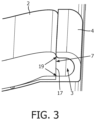
- Fig. 3 which schematically depicts a detail of the mattress accessory 9 according to Fig.
- FIG. 1 together with a mattress 2 in a perspective view shows the outer wall 4 in its natural undeformed state. Further, as depicted in Figs. 1, 2 , and 3 , the outer wall 4 of the cable duct 3 is C-shaped with its opening facing a side of the mattress 2.
- the mattress accessory 9 comprises a middle section 10 and two side section 11, wherein the middle section 10 is arranged below the mattress 2 and the side sections 11 protrude over the side edges on both sides of the mattress 2.
- the mattress accessory 9 with the cable ducts 3 may be held in place by the weight of the mattress 2 and also by the weight of the patient in case of an examination situation.
- the mattress accessory 9 is provided with an open slit 7, wherein the slit-confining outer walls 19 between which the slit 7 is formed are arranged in such a way relative to the side of the mattress 2 that the cable reception volume is circumferentially closed.
- the slit 7 may also be closed in a natural state in which the flexible regions of the outer wall 4 of the cable duct 3 are not deformed by an externa force.
- the two slit-confining outer wall areas 19 between which the longitudinal slit 7 is formed are in contact with each other such that the cable reception volume 5 is completely surrounded by the outer wall 4.
- the cable duct 3 is formed by a mattress accessory 9 which comprises a side section 11 and a fastening section 12 wherein the mattress accessory 9 is attached to the mattress 2 via the fastening section 12 such that the side section 11 protrudes over a side edge on a side of the mattress 2 and forms the cable duct 3.
- the mattress accessory 9 is attached to the mattress 2 by a hook-and-loop fastener 13.
- push buttons could be used for attaching the mattress accessory 9 to the mattress 2 push buttons (not shown) could be used.
- two such mattress accessories 9 are arranged on both long sides of the mattress 2, respectively, for providing a cable duct 3 on both opposite long sides of the mattress 2.
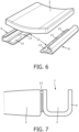
- Fig. 6 schematically depicts a mattress together with two mattress accessories 9 according to still another embodiment of the invention.
- the mattress accessories 9 are attached to the two opposite long sides of the mattress 2, respectively.
- the mattress accessories 9 also comprise hook-and-loop fasteners 13 for attaching them to the mattress 2.
- the mattress accessories 9 each comprise a region which extends under the mattress 2 and acts as a fastening section 12 such that the hook-and-loop fasteners 13 may interact with respective counter parts of the mattress 2 which are arranged on the bottom of the mattress 2. Similar to the embodiment shown in Figs. 1, 2 , and 3 , this allows for a design of the cable duct 3 with C-shaped outer walls 4 which provide for a permanent slit 7 which is closed by a side of the mattress 2 when the mattress accessories 9 are attached to the mattress 2.
- FIG. 7 which schematically depicts a detail of a mattress 2 and a mattress accessory 9 which comprises an open slit 7 on the top, also in case of a permanently open slit 7 it is not absolutely necessary to cover the slit 7.
- a cable When a cable is arranged in the cable reception volume 5 it will typically lie on the bottom of the reception volume 5 and, hence, it is less likely that the cable is accidentally touched compared with a situation in which the cable is placed on the mattress 2 next to the patient.
- Fig. 5 schematically depicts a detail of a MR apparatus with an examination table.
- the examination table may be equipped with an arm support 14 for the patient.
- the examination table may comprise a strap opening 15 and a coil cable opening 16.
- the flexible outer wall 4 can be folded up to access these strap opening 15 and the coil cable opening 16.
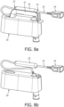
- Fig. 8a schematically depicts an adaptor interface 20 of an examination table with a handle 21 according to an embodiment of the invention in a perspective view.
- the adaptor interface 20 comprises a cable 23 with a balun 25 and a connector 24 which provides a connectivity for a coil cable (not shown).
- the handle 21 provides a gripping area and comprises a groove 22 to accommodate the cable 23 and/or the balun 25 of the cable 23. This helps avoiding that the cable 23 and/or the balun 25 annoys the patient or a nurse or medical doctor which prepares the patient for examination.
- Fig. 8b in general depicts the same adaptor interface 20 as Fig. 8a wherein the depiction of the handle 21 is omitted for better showing the routing of the cable 23.
- REFERENCE SYMBOL LIST arrangement 1 mattress 2 cable duct 3 outer wall 4 cable reception volume 5 MR apparatus 6 longitudinal slit 7 axis which runs parallel to the long side of the mattress 8 mattress accessory 9 middle section 10 side section 11 fastening section 12 hook-and-loop fastener 13 arm support 14 strap opening 15 coil cable opening 16 side portion on the long side of the mattress 17 examination table 18 slit-confining outer wall areas 19 adaptor interface 20 handle 21 groove 22 cable 23 connector 24 balun 25
Landscapes
- Health & Medical Sciences (AREA)
- Life Sciences & Earth Sciences (AREA)
- Engineering & Computer Science (AREA)
- Biomedical Technology (AREA)
- Medical Informatics (AREA)
- Veterinary Medicine (AREA)
- Biophysics (AREA)
- Nuclear Medicine, Radiotherapy & Molecular Imaging (AREA)
- Pathology (AREA)
- Radiology & Medical Imaging (AREA)
- Public Health (AREA)
- Heart & Thoracic Surgery (AREA)
- Physics & Mathematics (AREA)
- Molecular Biology (AREA)
- Surgery (AREA)
- Animal Behavior & Ethology (AREA)
- General Health & Medical Sciences (AREA)
- Physiology (AREA)
- Computer Vision & Pattern Recognition (AREA)
- Magnetic Resonance Imaging Apparatus (AREA)
Priority Applications (5)
| Application Number | Priority Date | Filing Date | Title |
|---|---|---|---|
| EP22757293.0A EP4388334B1 (de) | 2021-08-20 | 2022-07-28 | Matratze für einen untersuchungstisch eines mrt-geräts mit einem kabelkanal |
| PCT/EP2022/071211 WO2023020803A1 (en) | 2021-08-20 | 2022-07-28 | Mattress for an examination table of a mri apparatus equipped with a cable duct |
| CN202280056475.5A CN117836646A (zh) | 2021-08-20 | 2022-07-28 | 用于mri设备的检查台的配备有电缆管道的床垫 |
| JP2024508463A JP2024529680A (ja) | 2021-08-20 | 2022-07-28 | ケーブルダクトを有するmri装置の検査テーブル用マットレス |
| US18/684,265 US20240350091A1 (en) | 2021-08-20 | 2022-07-28 | Mattress for an examination table of a mri apparatus equipped with a cable duct |
Applications Claiming Priority (1)
| Application Number | Priority Date | Filing Date | Title |
|---|---|---|---|
| CN2021113712 | 2021-08-20 |
Publications (1)
| Publication Number | Publication Date |
|---|---|
| EP4137833A1 true EP4137833A1 (de) | 2023-02-22 |
Family
ID=84958402
Family Applications (1)
| Application Number | Title | Priority Date | Filing Date |
|---|---|---|---|
| EP21198791.2A Withdrawn EP4137833A1 (de) | 2021-08-20 | 2021-09-24 | Matratze für einen untersuchungstisch eines mrt-geräts mit einem kabelkanal |
Country Status (1)
| Country | Link |
|---|---|
| EP (1) | EP4137833A1 (de) |
Citations (2)
| Publication number | Priority date | Publication date | Assignee | Title |
|---|---|---|---|---|
| US20130176029A1 (en) | 2012-01-10 | 2013-07-11 | Toshiba Medical Systems Corporation | Bed apparatus for magnetic resonance imaging apparatus and magnetic resonance imaging apparatus |
| US20140361769A1 (en) * | 2013-06-05 | 2014-12-11 | Donald Hardie | Signal Transmissions to and from a Local Coil of a Magnetic Resonance System |
-
2021
- 2021-09-24 EP EP21198791.2A patent/EP4137833A1/de not_active Withdrawn
Patent Citations (2)
| Publication number | Priority date | Publication date | Assignee | Title |
|---|---|---|---|---|
| US20130176029A1 (en) | 2012-01-10 | 2013-07-11 | Toshiba Medical Systems Corporation | Bed apparatus for magnetic resonance imaging apparatus and magnetic resonance imaging apparatus |
| US20140361769A1 (en) * | 2013-06-05 | 2014-12-11 | Donald Hardie | Signal Transmissions to and from a Local Coil of a Magnetic Resonance System |
Non-Patent Citations (1)
| Title |
|---|
| PHILIPS: "Application Guide Volume 1 - Basics Achieva Release 3-2 Series - Section 5.22", PHILIPS HEALTHCARE NEDERLAND, 1 September 2012 (2012-09-01), pages 130 - 146, XP002806331 * |
Similar Documents
| Publication | Publication Date | Title |
|---|---|---|
| US7806376B2 (en) | Medical instrument | |
| US7869858B2 (en) | Patient table system and apparatus | |
| EP4388334B1 (de) | Matratze für einen untersuchungstisch eines mrt-geräts mit einem kabelkanal | |
| JP2006314793A (ja) | 外科用患者テーブルのためのシステム、方法及び装置 | |
| US20110173753A1 (en) | Specialized tabletops for medical imaging | |
| US20150005618A1 (en) | MRI Transfer Station | |
| EP3508129A1 (de) | Mrt-transfertischanordnung | |
| US6037773A (en) | Magnetic resonance imaging apparatus | |
| JP2014004362A (ja) | 乳児患者移送装置 | |
| CA2960842C (en) | Infant patient transfer device with vapor barrier | |
| US8689798B2 (en) | Protective medical device cushion and method for use thereof | |
| CN114847993A (zh) | 模块化超声探头管理系统 | |
| JP3497953B2 (ja) | Mri用ボディープローブ及びmri装置 | |
| CN110840481A (zh) | 超声系统探头保持器 | |
| CN110709007B (zh) | 血压计用套以及血压计 | |
| CN114028709A (zh) | 一种阀固定组件及具有该阀固定组件的介入手术机器人 | |
| JP2005507278A (ja) | 医療検査装置とフレーム及び患者テーブルの結合体との組立体、並びにこのような結合体 | |
| EP1943950A1 (de) | Röntgenstrahlendetektionsanordnung | |
| IL224790A (en) | Bedding for a newborn that is ahead of its time | |
| US8839470B2 (en) | Medical image table assembly and method of manufacturing the same | |
| CN111093440B (zh) | 包括推针固定组件的被褥的改进 | |
| US20020079898A1 (en) | Device for stabilizing parts of a body particularly for computed tomography diagnostics | |
| EP2809229A1 (de) | Mrt-übertragungsstation | |
| KR102127976B1 (ko) | 초음파 진단기의 선명도가 개선된 프로브용 커버 조립체 | |
| JP2015217153A (ja) | 医療台 |
Legal Events
| Date | Code | Title | Description |
|---|---|---|---|
| PUAI | Public reference made under article 153(3) epc to a published international application that has entered the european phase |
Free format text: ORIGINAL CODE: 0009012 |
|
| STAA | Information on the status of an ep patent application or granted ep patent |
Free format text: STATUS: THE APPLICATION HAS BEEN PUBLISHED |
|
| AK | Designated contracting states |
Kind code of ref document: A1 Designated state(s): AL AT BE BG CH CY CZ DE DK EE ES FI FR GB GR HR HU IE IS IT LI LT LU LV MC MK MT NL NO PL PT RO RS SE SI SK SM TR |
|
| STAA | Information on the status of an ep patent application or granted ep patent |
Free format text: STATUS: THE APPLICATION IS DEEMED TO BE WITHDRAWN |
|
| 18D | Application deemed to be withdrawn |
Effective date: 20230823 |