EP4137815A1 - Failure prediction system - Google Patents
Failure prediction system Download PDFInfo
- Publication number
- EP4137815A1 EP4137815A1 EP21789345.2A EP21789345A EP4137815A1 EP 4137815 A1 EP4137815 A1 EP 4137815A1 EP 21789345 A EP21789345 A EP 21789345A EP 4137815 A1 EP4137815 A1 EP 4137815A1
- Authority
- EP
- European Patent Office
- Prior art keywords
- failure prediction
- equipment
- parameter
- hydraulic oil
- parameters
- Prior art date
- Legal status (The legal status is an assumption and is not a legal conclusion. Google has not performed a legal analysis and makes no representation as to the accuracy of the status listed.)
- Granted
Links
Images




Classifications
-
- G—PHYSICS
- G01—MEASURING; TESTING
- G01N—INVESTIGATING OR ANALYSING MATERIALS BY DETERMINING THEIR CHEMICAL OR PHYSICAL PROPERTIES
- G01N33/00—Investigating or analysing materials by specific methods not covered by groups G01N1/00 - G01N31/00
- G01N33/26—Oils; Viscous liquids; Paints; Inks
- G01N33/28—Oils, i.e. hydrocarbon liquids
- G01N33/2888—Lubricating oil characteristics, e.g. deterioration
-
- G—PHYSICS
- G01—MEASURING; TESTING
- G01N—INVESTIGATING OR ANALYSING MATERIALS BY DETERMINING THEIR CHEMICAL OR PHYSICAL PROPERTIES
- G01N27/00—Investigating or analysing materials by the use of electric, electrochemical, or magnetic means
- G01N27/02—Investigating or analysing materials by the use of electric, electrochemical, or magnetic means by investigating impedance
- G01N27/04—Investigating or analysing materials by the use of electric, electrochemical, or magnetic means by investigating impedance by investigating resistance
- G01N27/06—Investigating or analysing materials by the use of electric, electrochemical, or magnetic means by investigating impedance by investigating resistance of a liquid
-
- G—PHYSICS
- G01—MEASURING; TESTING
- G01N—INVESTIGATING OR ANALYSING MATERIALS BY DETERMINING THEIR CHEMICAL OR PHYSICAL PROPERTIES
- G01N33/00—Investigating or analysing materials by specific methods not covered by groups G01N1/00 - G01N31/00
- G01N33/26—Oils; Viscous liquids; Paints; Inks
- G01N33/28—Oils, i.e. hydrocarbon liquids
-
- G—PHYSICS
- G05—CONTROLLING; REGULATING
- G05B—CONTROL OR REGULATING SYSTEMS IN GENERAL; FUNCTIONAL ELEMENTS OF SUCH SYSTEMS; MONITORING OR TESTING ARRANGEMENTS FOR SUCH SYSTEMS OR ELEMENTS
- G05B23/00—Testing or monitoring of control systems or parts thereof
- G05B23/02—Electric testing or monitoring
- G05B23/0205—Electric testing or monitoring by means of a monitoring system capable of detecting and responding to faults
- G05B23/0218—Electric testing or monitoring by means of a monitoring system capable of detecting and responding to faults characterised by the fault detection method dealing with either existing or incipient faults
- G05B23/0224—Process history based detection method, e.g. whereby history implies the availability of large amounts of data
- G05B23/024—Quantitative history assessment, e.g. mathematical relationships between available data; Functions therefor; Principal component analysis [PCA]; Partial least square [PLS]; Statistical classifiers, e.g. Bayesian networks, linear regression or correlation analysis; Neural networks
-
- G—PHYSICS
- G05—CONTROLLING; REGULATING
- G05B—CONTROL OR REGULATING SYSTEMS IN GENERAL; FUNCTIONAL ELEMENTS OF SUCH SYSTEMS; MONITORING OR TESTING ARRANGEMENTS FOR SUCH SYSTEMS OR ELEMENTS
- G05B23/00—Testing or monitoring of control systems or parts thereof
- G05B23/02—Electric testing or monitoring
- G05B23/0205—Electric testing or monitoring by means of a monitoring system capable of detecting and responding to faults
- G05B23/0218—Electric testing or monitoring by means of a monitoring system capable of detecting and responding to faults characterised by the fault detection method dealing with either existing or incipient faults
- G05B23/0243—Electric testing or monitoring by means of a monitoring system capable of detecting and responding to faults characterised by the fault detection method dealing with either existing or incipient faults model based detection method, e.g. first-principles knowledge model
- G05B23/0254—Electric testing or monitoring by means of a monitoring system capable of detecting and responding to faults characterised by the fault detection method dealing with either existing or incipient faults model based detection method, e.g. first-principles knowledge model based on a quantitative model, e.g. mathematical relationships between inputs and outputs; functions: observer, Kalman filter, residual calculation, Neural Networks
-
- G—PHYSICS
- G05—CONTROLLING; REGULATING
- G05B—CONTROL OR REGULATING SYSTEMS IN GENERAL; FUNCTIONAL ELEMENTS OF SUCH SYSTEMS; MONITORING OR TESTING ARRANGEMENTS FOR SUCH SYSTEMS OR ELEMENTS
- G05B23/00—Testing or monitoring of control systems or parts thereof
- G05B23/02—Electric testing or monitoring
- G05B23/0205—Electric testing or monitoring by means of a monitoring system capable of detecting and responding to faults
- G05B23/0259—Electric testing or monitoring by means of a monitoring system capable of detecting and responding to faults characterized by the response to fault detection
- G05B23/0283—Predictive maintenance, e.g. involving the monitoring of a system and, based on the monitoring results, taking decisions on the maintenance schedule of the monitored system; Estimating remaining useful life [RUL]
Definitions
- This invention relates to a failure prediction system.
- the hydraulic oil used in equipment oxidizes and gradually deteriorates with equipment use. Therefore, in order to avoid equipment failure and shortened equipment life, the deterioration state of the hydraulic oil must be properly estimated, and the fluid must be replenished or replaced at the appropriate time.
- Patent Document 1 JP 2016-20864 A .
- the purpose of the present invention is to provide a failure prediction system that outputs not only the state of hydraulic oil but also information on failure prediction of equipment by processing in real time.
- At least one embodiment of the present invention proposes a failure prediction system of an equipment characterized in comprising: an oil condition sensor attached to the equipment; a parameter calculator to calculate values of the plurality of parameters indicating the state of the hydraulic oil based on a correlation information between a sensor output of the oil condition sensor and the values of the plurality of parameters indicating the state of the hydraulic oil and the sensor output; a failure prediction determiner that predicts a failure of the equipment based on the values of the parameters and identifies and outputs the parameters that are inferred as the cause of the failure prediction.
- the failure prediction system 1 comprises an oil condition sensor 10, a parameter calculator 20, and a failure prediction determiner 30.
- the oil condition sensor 10 is an oil condition sensor that detects the oil condition of the hydraulic oil, is mounted so that the sensing member is immersed in the hydraulic oil of the equipment 100 to be sensed, and acquires information including, for example, the relative permittivity and conductivity of the hydraulic oil.
- the oil condition sensor 10 is connected to the parameter calculator 20 (described below) wirelessly or via a network, and outputs the information acquired by the oil condition sensor 10 sequentially or at the request of the parameter calculator 20.
- the parameter calculator 20 obtains the values of the plurality of parameters indicating the state of the hydraulic oil based on the correlation information between the sensor output of the oil condition sensor 10 and the values of the plurality of parameters indicating the state of the hydraulic oil and the sensor output.
- parameters indicating the condition of the hydraulic oil may be parameters including total acid number, degree of contamination, metallic elements, and moisture.
- the parameter calculator 20 may be a stand-alone device or, for example, a server in the cloud.
- the failure prediction determiner 30 outputs failure prediction information of equipment 100 in real time from the values of correlated parameters.
- the failure prediction determiner 30 inputs the values of correlated parameters, performs machine learning, and outputs failure prediction information of the equipment 100.
- the failure prediction information the information including the timing of failure and the contribution of parameters indicating the condition of the hydraulic oil can be exemplified.
- the failure prediction determiner 30 may be a stand-alone device or, for example, a server in the cloud.
- It may be a stand-alone device that combines the failure prediction determiner 30 and the parameter calculator 20, or it may be a server in the cloud, for example.
- the parameter calculator 20 consists of a calculator 21, a correlation function storage 22, and a controller 23, as shown in Fig. 2 .
- the calculator 21 calculates values of parameters indicating the oil condition of the hydraulic oil based on information obtained from the oil condition sensor 10, for example, sensor information including relative permittivity and conductivity, and correlation functions stored in the correlation function storage 22 described below.
- the correlation function storage 22 stores correlation functions that indicate the correlation between sensor information obtained from the oil condition sensor 10 and parameters indicating the oil condition of the hydraulic oil.
- Correlation functions are calculated by mathematical regression from the vast amount of data collected and include, for example, correlation functions between relative permittivity and total acid number, relative permittivity and degree of contamination, relative permittivity and moisture, conductivity and degree of contamination, conductivity and metallic elements, and conductivity and moisture.
- the controller 23 controls the operation of the calculator 21 according to a control program stored in ROM (Read Only Memory) etc.
- the failure prediction determiner 30 comprises a failure prediction determination algorithm 31, a learning model storage 32, a controller 33, and an information memory 34.
- the failure prediction determination algorithm 31 is an algorithm for performing machine learning in the failure prediction determiner 30, and it takes as input the values of the parameters indicating the oil condition of the hydraulic oil calculated in the parameter calculator 20, performs machine learning using the learning model described below, and outputs failure prediction information including failure timing and contribution of the parameters indicating the oil condition of the hydraulic oil, for example, and corresponding messages to prevent failure.
- a boosting that forms a decision tree structure can be exemplified.
- the learning model storage 32 stores learning models generated in advance.
- the learning model is data from which rules and patterns (outputs) are learned based on input data.
- the controller 33 controls the operation of the failure prediction determiner 30 according to a control program stored in ROM (Read Only Memory) etc.
- the ROM and other memory elements of the controller 33 store corresponding messages etc. in response to failure prediction information to prevent failures before they occur.
- the controller 33 causes all of the equipment 100 to perform failure prediction determination. In other words, the controller 33 causes the same model and the same period of use of the equipment 100 to perform the failure prediction determination.
- the information memory 34 stores a database linking the information input from the parameter calculator 20 and the failure prediction information output from the failure prediction determination algorithm 31.
- the controller 23 of the parameter calculator 20 monitors, for example, the output from the oil condition sensor 10 at predetermined time intervals, and outputs sensor information obtained from the oil condition sensor 10, including, for example, relative permittivity and conductivity, to the calculator 21 (step S101).
- the calculator 21 of the parameter calculator 20 calculates the value of the parameter indicating the oil condition of the hydraulic oil based on the information input from the controller 23, for example, sensor information including relative permittivity and conductivity, and the correlation function stored in the correlation function storage 22 described below (step S102).
- the correlation function storage 22 stores correlation functions between relative permittivity and degree of contamination, correlation functions between relative permittivity and moisture, correlation functions between conductivity and degree of contamination, correlation functions between conductivity and metallic elements, correlation functions between conductivity and moisture, etc., including the correlation function between permittivity and total acid number as shown in Fig. 5 .
- the calculator 21 calculates the values of parameters indicating the oil condition of the hydraulic oil, for example, total acid number, degree of contamination, metallic elements, and moisture, based on sensor information including relative permittivity and conductivity and correlation functions stored in the correlation function storage 22, and outputs them to the failure prediction determiner 30.
- the controller 33 of the failure prediction determiner 30 incorporates the calculation results of the parameter calculator 20 into the failure prediction determination algorithm 31.
- the failure prediction determination algorithm 31 takes as input the values of parameters indicating the oil condition of the hydraulic oil calculated in the parameter calculator 20 and executes machine learning using a learning model to display on a display (not shown) or output to a user terminal or the like in real time, for example, failure prediction information including failure timing, contribution of parameters indicating the oil condition, and corresponding messages etc. for preventing failures (step S103) .
- the information output from the parameter calculator 20 and the failure prediction information output from the failure prediction determination algorithm 31 are stored in the information memory 34 in the form of a database.
- the parameter calculator 20 obtains the values of multiple parameters indicating the state of the hydraulic oil, and the failure prediction determiner 30 predicts a failure of the equipment 100 from the parameter values, identifies parameters that are speculated as the cause of failure prediction, and outputs failure prediction information in real time.
- the oil condition of the hydraulic oil and the failure of the equipment 100 can be monitored in real time based on the sensor outputs of the oil condition sensor 10 attached to the equipment 100 and the correlation information between the values of multiple parameters indicating the condition of the hydraulic oil and the sensor outputs, which enables early determination of when to replace the hydraulic oil appropriately and the failure of the equipment 100.
- the parameter calculator 20 obtains the values of multiple parameters indicating the state of the hydraulic oil, and the failure prediction determiner 30 predicts failure of the equipment 100 from the values of the parameters, identifies the parameters that are inferred as the cause of the failure prediction, and outputs failure prediction information in real time.
- the failure prediction system 1 since the failure prediction system 1 notifies users of failure prediction information after predicting the condition of hydraulic oil, the basis of failure prediction information can be presented to users based on the prediction results of hydraulic oil conditions.
- the failure prediction system 1 since the failure prediction system 1 according to this embodiment displays on a display (not shown) or outputs to a user terminal or the like in real time information including the time of failure, the contribution of parameters indicating the state of the hydraulic oil, and a corresponding message to prevent failure, it can prompt the user to act quickly.
- the parameter calculator in the failure prediction system 1 obtains the values of the parameters from the sensor outputs of the oil condition sensors using the first learning data generated by machine learning with the previously measured parameter values as teacher data.
- the parameter calculator 20 in the failure prediction system 1 stores, for example, a correlation function between sensor outputs mathematically calculated based on collected data and parameters indicating the state of hydraulic oil, and uses first learning data generated by machine learning with previously measured parameter values as teacher data to obtain the values of parameters from the sensor outputs of the oil condition sensors.
- the failure prediction determiner in the failure prediction system 1 identifies and outputs said parameters that are inferred as causes of failure prediction of equipment from the values of the parameters calculated by the parameter calculator using a second learning model generated by machine learning, with the objective variable being whether the equipment is in a failed state or not, or in a state that is predictive of failure, and the parameter being an explanatory variable.
- the failure prediction determiner in the failure prediction system 1 identifies and outputs said parameters that are inferred as causes of failure prediction of equipment from the values of parameters calculated by the parameter calculator based on a second learning model generated by machine learning, using as objective variables whether the equipment is in a failed state or not, or whether it is in a state that is predicted to fail, and parameters as explanatory variables.
- the controller 33 in the failure prediction system 1 will have the failure prediction determination performed for all equipment 100, i.e., for devices of the same model and with the same period of use.
- the failure prediction system 1 by having the failure prediction determination performed on, for example, equipment 100 of the same model and with the same period of use, the failure prediction information for each equipment 100 can be reported to the user.
- a function to generate a learning model may be added to the failure prediction system 1, and the learning model may be generated by the information used in the process of acquiring failure prediction information and the failure prediction information, and the learning model used in the process of acquiring failure prediction information may be updated.
- the accuracy of generating failure prediction information in the failure prediction system 1 can be improved by updating the learning model using the newly obtained information.
- the failure prediction system 1A comprises an oil condition sensor 10, a parameter calculator 20, and a failure prediction determiner 30A.
- the failure prediction determiner 30A outputs failure prediction information of equipment 100 in real time from the values of correlated parameters.
- the failure prediction determiner 30A does not perform machine learning on the next and subsequent contribution for parameters whose contribution is lower than the set value.
- the failure prediction determiner 30A comprises a failure prediction determination algorithm 31, a learning model storage 32, a controller 33A, and an information memory 34.
- the controller 33A controls the operation of the failure prediction determiner 30A according to a control program stored in ROM (Read Only Memory) etc.
- the controller 33A detects parameters whose contribution is lower than the set value based on the database linking the information input from the parameter calculator 20 and the failure prediction information output from the failure prediction determination algorithm 31 stored in the information memory 34, and controls the failure prediction determiner 30A not to perform machine learning on the contribution from the next time onward for the parameter in question.
- the controller 23 of the parameter calculator 20 monitors the output from the oil condition sensor 10 at predetermined time intervals and outputs sensor information obtained from the oil condition sensor 10, including, for example, relative permittivity and conductivity, to the calculator 21 (step S201).
- the calculator 21 of the parameter calculator 20 calculates values of parameters indicating the oil condition of the hydraulic oil based on information input from the controller 23, for example, sensor information including relative permittivity and conductivity, and correlation functions stored in the correlation function storage 22 described below (step S202).
- the controller 33A of the failure prediction determiner 30A determines the presence or absence of parameters whose contribution is lower than a set value based on a database stored in the information memory 34 that links the information input from the parameter calculator 20 and the failure prediction information output from the failure prediction determination algorithm 31 (step S203).
- the controller 33A of the failure prediction determiner 30A executes control so that all calculation results of the parameter calculator 20 are incorporated into the failure prediction determination algorithm 31, wherein the failure prediction determination algorithm 31 takes as input the values of parameters indicating the oil state of the hydraulic oil calculated in the parameter calculator 20 and executes machine learning using a learning model to display on a display (not shown) or output to a user terminal or the like in real time, for example, failure prediction information including failure timing, contribution of parameters indicating the condition of the hydraulic oil, and corresponding messages for preventing failures (step S205).
- the controller 33A of the failure prediction determiner 30A executes control so that the calculated results of the parameters excluding the calculation results of the parameters whose contribution is lower than the set value among the calculation results of the parameter calculator 20 are incorporated into the failure prediction determination algorithm 31, wherein the failure prediction determination algorithm 31 takes as input the values of parameters indicating the oil state of the hydraulic oil calculated in the parameter calculator 20 and executes machine learning using a learning model to display on a display (not shown) or output to a user terminal or the like in real time, for example, failure prediction information including failure timing, contribution of parameters indicating the oil condition, and corresponding messages for preventing failures (step S204).
- the controller 33A of the failure prediction determiner 30A in the failure prediction system 1A determines the presence or absence of parameters whose contribution is lower than a set value based on a database stored in the information memory 34 that links the information input from the parameter calculator 20 and the failure prediction information output from the failure prediction determination algorithm 31, and when it is determined that there is a parameter in the database whose contribution is lower than the set value ("YES" in step S203), it executes control so that the calculated results of the parameters excluding the calculation results of the parameters whose contribution is lower than the set value among the calculation results of the parameter calculator 20 are incorporated into the failure prediction determination algorithm 31, wherein the failure prediction determination algorithm 31 takes as input the values of parameters indicating the oil state of the hydraulic oil calculated in the parameter calculator 20 and executes machine learning using a learning model to display on a display (not shown) or output to a user terminal or the like in real time, for example, failure prediction information including failure timing, contribution of parameters indicating the oil condition, and corresponding messages for preventing failures.
- the processing load of the failure prediction determiner 30A can be reduced.
- the parameter calculator 20 calculates the value of the parameter indicating the oil condition of the hydraulic oil based on the information obtained from the oil condition sensor 10, for example, sensor information including relative permittivity and conductivity, and a correlation function calculated by mathematical regression from a vast amount of data stored in the correlation function storage 22 described below.
- the parameter calculator 20 may calculate the value of the parameter from the correlation between the sensor information including relative permittivity and conductivity obtained from a vast amount of data using a specific algorithm and the value of the parameter indicating the oil condition of the hydraulic oil.
- the values of parameters can be calculated with a high degree of accuracy even when the relationship between sensor information including relative permittivity and conductivity and the values of parameters indicating the oil condition of the hydraulic oil have a relationship that cannot be expressed by a function.
- Variation 1 it is exemplified that different algorithms are applied to the parameter calculator 20 and the failure prediction determiner 30 and 30A to perform failure prediction determination. However, under the condition that it is limited to certain specific data, such as data with high dielectric constant, for example, the parameter calculator 20 and the failure prediction determiner 30 and 30A may be operated using one algorithm.
- the application of a machine learning classification algorithm to the failure prediction determiners 30 and 30A is exemplified, but a theory-based or rule-based algorithm may also be applied.
- the failure prediction determiner 30 may perform machine learning of the contribution even if the equipment 100 is the same model as the equipment 100 for which machine learning of the contribution of the parameters indicating the condition of the hydraulic oil has been performed so far.
- the failure prediction systems 1 and 1A of the present invention can be realized by recording the processes of the failure prediction systems 1 and 1A on a recording medium readable by a computer system and having the program recorded on this recording medium read and executed by the failure prediction systems 1 and 1A.
- the computer system here includes hardware such as an OS and peripheral devices.
- Computer system shall include the homepage provision environment (or display environment) if the WWW (World Wide Web) system is used.
- the above program may be transmitted from a computer system storing this program in a memory device or the like to another computer system via a transmission medium or by transmission waves in a transmission medium.
- transmission medium for transmitting the program refers to a medium that has the function of transmitting information, such as a network (communication network) such as the Internet or a communication channel (communication line) such as a telephone line.
- the above programs may also be those that can be used to realize some of the aforementioned functions. Furthermore, it may be a so-called difference file (difference program), which can realize the aforementioned functions in combination with a program already recorded in the computer system.
- difference file difference program
- failure prediction system it is possible to output not only the condition of hydraulic oil but also information on failure prediction of equipment through real-time processing.
Landscapes
- Engineering & Computer Science (AREA)
- Physics & Mathematics (AREA)
- Chemical & Material Sciences (AREA)
- General Physics & Mathematics (AREA)
- Life Sciences & Earth Sciences (AREA)
- Health & Medical Sciences (AREA)
- Automation & Control Theory (AREA)
- Chemical Kinetics & Catalysis (AREA)
- Pathology (AREA)
- Biochemistry (AREA)
- Immunology (AREA)
- General Health & Medical Sciences (AREA)
- Analytical Chemistry (AREA)
- General Chemical & Material Sciences (AREA)
- Medicinal Chemistry (AREA)
- Food Science & Technology (AREA)
- Oil, Petroleum & Natural Gas (AREA)
- Artificial Intelligence (AREA)
- Evolutionary Computation (AREA)
- Mathematical Physics (AREA)
- Electrochemistry (AREA)
- Fluid-Pressure Circuits (AREA)
- Testing And Monitoring For Control Systems (AREA)
- Testing Of Devices, Machine Parts, Or Other Structures Thereof (AREA)
- Investigating Or Analyzing Materials By The Use Of Electric Means (AREA)
Abstract
Description
- This invention relates to a failure prediction system.
- The hydraulic oil used in equipment oxidizes and gradually deteriorates with equipment use. Therefore, in order to avoid equipment failure and shortened equipment life, the deterioration state of the hydraulic oil must be properly estimated, and the fluid must be replenished or replaced at the appropriate time.
- In order to meet the above requirements, a technology has been disclosed to reduce the time required to determine the degree of deterioration of the hydraulic oil after the hydraulic oil in use in the equipment is sampled (see, for example, patent document 1).
- [Patent Document 1]
JP 2016-20864 A - However, the technology described in the
patent document 1 assumes that hydraulic oil is collected while the equipment is in use. As a result, equipment operation must be stopped when collecting hydraulic oil, which affects productivity and work efficiency. - Related to the above problem, assuming that hydraulic oil is collected while the equipment is in use, the condition of the hydraulic oil cannot be evaluated frequently, making it difficult to perform predictive maintenance accurately even if the determination time is reduced.
- Furthermore, although the technology described in
patent document 1 estimates the degree of deterioration of hydraulic oil, it does not determine equipment failure. - The purpose of the present invention, therefore, is to provide a failure prediction system that outputs not only the state of hydraulic oil but also information on failure prediction of equipment by processing in real time.
- First Aspect: At least one embodiment of the present invention proposes a failure prediction system of an equipment characterized in comprising: an oil condition sensor attached to the equipment; a parameter calculator to calculate values of the plurality of parameters indicating the state of the hydraulic oil based on a correlation information between a sensor output of the oil condition sensor and the values of the plurality of parameters indicating the state of the hydraulic oil and the sensor output; a failure prediction determiner that predicts a failure of the equipment based on the values of the parameters and identifies and outputs the parameters that are inferred as the cause of the failure prediction.
-
-
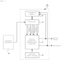
Fig. 1 shows the configuration of failure prediction system according to the first embodiment. -
Fig. 2 shows the configuration of the parameter calculator according to the first embodiment. -
Fig. 3 shows the configuration of the failure prediction determiner according to the first embodiment. -
Fig. 4 is the flowchart showing the process of the failure prediction system according to the first embodiment. -
Fig. 5 shows the correlation stored in the correlation function storage of the parameter calculator according to the first embodiment. -
Fig. 6 is the flowchart showing the process of the failure prediction system according to the second embodiment. - Hereinafter, a
failure prediction system 1 according to a first embodiment of the present invention will be described with reference toFigs. 1 to 5 . - The configuration of a
failure prediction system 1 according to the first embodiment of the present invention will be described with reference toFigs 1 to 3 . - As shown in
Fig. 1 , thefailure prediction system 1 comprises anoil condition sensor 10, aparameter calculator 20, and a failure prediction determiner 30. - The
oil condition sensor 10 is an oil condition sensor that detects the oil condition of the hydraulic oil, is mounted so that the sensing member is immersed in the hydraulic oil of theequipment 100 to be sensed, and acquires information including, for example, the relative permittivity and conductivity of the hydraulic oil. - The
oil condition sensor 10 is connected to the parameter calculator 20 (described below) wirelessly or via a network, and outputs the information acquired by theoil condition sensor 10 sequentially or at the request of theparameter calculator 20. - The
parameter calculator 20 obtains the values of the plurality of parameters indicating the state of the hydraulic oil based on the correlation information between the sensor output of theoil condition sensor 10 and the values of the plurality of parameters indicating the state of the hydraulic oil and the sensor output. - The examples of parameters indicating the condition of the hydraulic oil may be parameters including total acid number, degree of contamination, metallic elements, and moisture.
- Here, the
parameter calculator 20 may be a stand-alone device or, for example, a server in the cloud. - The failure prediction determiner 30 outputs failure prediction information of
equipment 100 in real time from the values of correlated parameters. - Here, the failure prediction determiner 30 inputs the values of correlated parameters, performs machine learning, and outputs failure prediction information of the
equipment 100. - For example, as the failure prediction information, the information including the timing of failure and the contribution of parameters indicating the condition of the hydraulic oil can be exemplified.
- The failure prediction determiner 30 may be a stand-alone device or, for example, a server in the cloud.
- It may be a stand-alone device that combines the failure prediction determiner 30 and the
parameter calculator 20, or it may be a server in the cloud, for example. - The
parameter calculator 20 consists of acalculator 21, acorrelation function storage 22, and acontroller 23, as shown inFig. 2 . - The
calculator 21 calculates values of parameters indicating the oil condition of the hydraulic oil based on information obtained from theoil condition sensor 10, for example, sensor information including relative permittivity and conductivity, and correlation functions stored in thecorrelation function storage 22 described below. - The
correlation function storage 22 stores correlation functions that indicate the correlation between sensor information obtained from theoil condition sensor 10 and parameters indicating the oil condition of the hydraulic oil. - Correlation functions are calculated by mathematical regression from the vast amount of data collected and include, for example, correlation functions between relative permittivity and total acid number, relative permittivity and degree of contamination, relative permittivity and moisture, conductivity and degree of contamination, conductivity and metallic elements, and conductivity and moisture.
- The
controller 23 controls the operation of thecalculator 21 according to a control program stored in ROM (Read Only Memory) etc. - As shown in
Fig. 3 , the failure prediction determiner 30 comprises a failureprediction determination algorithm 31, alearning model storage 32, acontroller 33, and aninformation memory 34. - The failure
prediction determination algorithm 31 is an algorithm for performing machine learning in the failure prediction determiner 30, and it takes as input the values of the parameters indicating the oil condition of the hydraulic oil calculated in theparameter calculator 20, performs machine learning using the learning model described below, and outputs failure prediction information including failure timing and contribution of the parameters indicating the oil condition of the hydraulic oil, for example, and corresponding messages to prevent failure. - As an example of the failure
prediction determination algorithm 31, a boosting that forms a decision tree structure can be exemplified. - The
learning model storage 32 stores learning models generated in advance. Here, the learning model is data from which rules and patterns (outputs) are learned based on input data. - The
controller 33 controls the operation of the failure prediction determiner 30 according to a control program stored in ROM (Read Only Memory) etc. - In addition, the ROM and other memory elements of the
controller 33 store corresponding messages etc. in response to failure prediction information to prevent failures before they occur. - The
controller 33 causes all of theequipment 100 to perform failure prediction determination. In other words, thecontroller 33 causes the same model and the same period of use of theequipment 100 to perform the failure prediction determination. - The
information memory 34 stores a database linking the information input from theparameter calculator 20 and the failure prediction information output from the failureprediction determination algorithm 31. - Processing of the failure prediction system according to the first embodiment of the present invention will be described with reference to
Figs. 4 and 5 . - The
controller 23 of theparameter calculator 20 monitors, for example, the output from theoil condition sensor 10 at predetermined time intervals, and outputs sensor information obtained from theoil condition sensor 10, including, for example, relative permittivity and conductivity, to the calculator 21 (step S101). - The
calculator 21 of theparameter calculator 20 calculates the value of the parameter indicating the oil condition of the hydraulic oil based on the information input from thecontroller 23, for example, sensor information including relative permittivity and conductivity, and the correlation function stored in thecorrelation function storage 22 described below (step S102). - For example, the
correlation function storage 22 stores correlation functions between relative permittivity and degree of contamination, correlation functions between relative permittivity and moisture, correlation functions between conductivity and degree of contamination, correlation functions between conductivity and metallic elements, correlation functions between conductivity and moisture, etc., including the correlation function between permittivity and total acid number as shown inFig. 5 . - The
calculator 21 calculates the values of parameters indicating the oil condition of the hydraulic oil, for example, total acid number, degree of contamination, metallic elements, and moisture, based on sensor information including relative permittivity and conductivity and correlation functions stored in thecorrelation function storage 22, and outputs them to the failure prediction determiner 30. - The
controller 33 of the failure prediction determiner 30 incorporates the calculation results of theparameter calculator 20 into the failureprediction determination algorithm 31. - The failure
prediction determination algorithm 31 takes as input the values of parameters indicating the oil condition of the hydraulic oil calculated in theparameter calculator 20 and executes machine learning using a learning model to display on a display (not shown) or output to a user terminal or the like in real time, for example, failure prediction information including failure timing, contribution of parameters indicating the oil condition, and corresponding messages etc. for preventing failures (step S103) . - The information output from the
parameter calculator 20 and the failure prediction information output from the failureprediction determination algorithm 31 are stored in theinformation memory 34 in the form of a database. - As explained above, in the
failure prediction system 1 according to this embodiment, based on the sensor output of theoil condition sensor 10 attached to theequipment 100 and the correlation information between the sensor output and the values of multiple parameters indicating the state of the hydraulic oil, theparameter calculator 20 obtains the values of multiple parameters indicating the state of the hydraulic oil, and thefailure prediction determiner 30 predicts a failure of theequipment 100 from the parameter values, identifies parameters that are speculated as the cause of failure prediction, and outputs failure prediction information in real time. - Therefore, the oil condition of the hydraulic oil and the failure of the
equipment 100 can be monitored in real time based on the sensor outputs of theoil condition sensor 10 attached to theequipment 100 and the correlation information between the values of multiple parameters indicating the condition of the hydraulic oil and the sensor outputs, which enables early determination of when to replace the hydraulic oil appropriately and the failure of theequipment 100. - In the
failure prediction system 1 according to this embodiment, theparameter calculator 20 obtains the values of multiple parameters indicating the state of the hydraulic oil, and thefailure prediction determiner 30 predicts failure of theequipment 100 from the values of the parameters, identifies the parameters that are inferred as the cause of the failure prediction, and outputs failure prediction information in real time. - In other words, since the
failure prediction system 1 notifies users of failure prediction information after predicting the condition of hydraulic oil, the basis of failure prediction information can be presented to users based on the prediction results of hydraulic oil conditions. - In addition, since the
failure prediction system 1 according to this embodiment displays on a display (not shown) or outputs to a user terminal or the like in real time information including the time of failure, the contribution of parameters indicating the state of the hydraulic oil, and a corresponding message to prevent failure, it can prompt the user to act quickly. - The parameter calculator in the
failure prediction system 1 according to this embodiment obtains the values of the parameters from the sensor outputs of the oil condition sensors using the first learning data generated by machine learning with the previously measured parameter values as teacher data. - In other words, the
parameter calculator 20 in thefailure prediction system 1 according to this embodiment stores, for example, a correlation function between sensor outputs mathematically calculated based on collected data and parameters indicating the state of hydraulic oil, and uses first learning data generated by machine learning with previously measured parameter values as teacher data to obtain the values of parameters from the sensor outputs of the oil condition sensors. - Therefore, it is possible to predict how the values of parameters indicating the state of the hydraulic oil will change relative to changes in sensor output values due to the cumulative usage time of the
equipment 100 and other factors. - The failure prediction determiner in the
failure prediction system 1 according to this embodiment identifies and outputs said parameters that are inferred as causes of failure prediction of equipment from the values of the parameters calculated by the parameter calculator using a second learning model generated by machine learning, with the objective variable being whether the equipment is in a failed state or not, or in a state that is predictive of failure, and the parameter being an explanatory variable. - That is, for example, the failure prediction determiner in the
failure prediction system 1 according to this embodiment identifies and outputs said parameters that are inferred as causes of failure prediction of equipment from the values of parameters calculated by the parameter calculator based on a second learning model generated by machine learning, using as objective variables whether the equipment is in a failed state or not, or whether it is in a state that is predicted to fail, and parameters as explanatory variables. - Therefore, it is possible to output highly accurate information on failure prediction of equipment in a short period of time.
- The
controller 33 in thefailure prediction system 1 according to this embodiment will have the failure prediction determination performed for allequipment 100, i.e., for devices of the same model and with the same period of use. - In general, it is expected that similar failure prediction trends will appear for the same model of
equipment 100, but the failure prediction trends differ in the contribution of parameters indicating the condition of the hydraulic oil, depending on the user's usage. - Therefore, in the
failure prediction system 1 according to this embodiment, by having the failure prediction determination performed on, for example,equipment 100 of the same model and with the same period of use, the failure prediction information for eachequipment 100 can be reported to the user. - A function to generate a learning model may be added to the
failure prediction system 1, and the learning model may be generated by the information used in the process of acquiring failure prediction information and the failure prediction information, and the learning model used in the process of acquiring failure prediction information may be updated. - Thus, the accuracy of generating failure prediction information in the
failure prediction system 1 can be improved by updating the learning model using the newly obtained information. - Hereinafter, the failure prediction system 1A according to the second embodiment of the invention will be described with reference to
Fig. 6 . - The configuration of the failure prediction system 1A according to the second embodiment of the invention will be described.
- The failure prediction system 1A according to this embodiment comprises an
oil condition sensor 10, aparameter calculator 20, and a failure prediction determiner 30A. - Detailed descriptions of the components with the same symbols as in the first embodiment are omitted, since they have the same functions.
- The failure prediction determiner 30A outputs failure prediction information of
equipment 100 in real time from the values of correlated parameters. - The failure prediction determiner 30A does not perform machine learning on the next and subsequent contribution for parameters whose contribution is lower than the set value.
- The failure prediction determiner 30A comprises a failure
prediction determination algorithm 31, alearning model storage 32, a controller 33A, and aninformation memory 34. - Detailed descriptions of the components with the same symbols as in the first embodiment are omitted, since they have the same functions.
- The controller 33A controls the operation of the failure prediction determiner 30A according to a control program stored in ROM (Read Only Memory) etc.
- The controller 33A detects parameters whose contribution is lower than the set value based on the database linking the information input from the
parameter calculator 20 and the failure prediction information output from the failureprediction determination algorithm 31 stored in theinformation memory 34, and controls the failure prediction determiner 30A not to perform machine learning on the contribution from the next time onward for the parameter in question. - Processing of the failure prediction system 1A according to the second embodiment of the present invention will be described with reference to
Fig. 6 . - The
controller 23 of theparameter calculator 20, for example, monitors the output from theoil condition sensor 10 at predetermined time intervals and outputs sensor information obtained from theoil condition sensor 10, including, for example, relative permittivity and conductivity, to the calculator 21 (step S201). - The
calculator 21 of theparameter calculator 20 calculates values of parameters indicating the oil condition of the hydraulic oil based on information input from thecontroller 23, for example, sensor information including relative permittivity and conductivity, and correlation functions stored in thecorrelation function storage 22 described below (step S202). - The controller 33A of the failure prediction determiner 30A determines the presence or absence of parameters whose contribution is lower than a set value based on a database stored in the
information memory 34 that links the information input from theparameter calculator 20 and the failure prediction information output from the failure prediction determination algorithm 31 (step S203). - At this time, if it is determined that there is no parameter in the database whose contribution is lower than the set value ("NO" in step S203), the controller 33A of the failure prediction determiner 30A executes control so that all calculation results of the
parameter calculator 20 are incorporated into the failureprediction determination algorithm 31, wherein the failureprediction determination algorithm 31 takes as input the values of parameters indicating the oil state of the hydraulic oil calculated in theparameter calculator 20 and executes machine learning using a learning model to display on a display (not shown) or output to a user terminal or the like in real time, for example, failure prediction information including failure timing, contribution of parameters indicating the condition of the hydraulic oil, and corresponding messages for preventing failures (step S205). - On the other hand, if it is determined that there is parameter in the database whose contribution is lower than the set value ("YES" in step S203), the controller 33A of the failure prediction determiner 30A executes control so that the calculated results of the parameters excluding the calculation results of the parameters whose contribution is lower than the set value among the calculation results of the
parameter calculator 20 are incorporated into the failureprediction determination algorithm 31, wherein the failureprediction determination algorithm 31 takes as input the values of parameters indicating the oil state of the hydraulic oil calculated in theparameter calculator 20 and executes machine learning using a learning model to display on a display (not shown) or output to a user terminal or the like in real time, for example, failure prediction information including failure timing, contribution of parameters indicating the oil condition, and corresponding messages for preventing failures (step S204). - As explained above, the controller 33A of the failure prediction determiner 30A in the failure prediction system 1A according to this embodiment determines the presence or absence of parameters whose contribution is lower than a set value based on a database stored in the
information memory 34 that links the information input from theparameter calculator 20 and the failure prediction information output from the failureprediction determination algorithm 31, and when it is determined that there is a parameter in the database whose contribution is lower than the set value ("YES" in step S203), it executes control so that the calculated results of the parameters excluding the calculation results of the parameters whose contribution is lower than the set value among the calculation results of theparameter calculator 20 are incorporated into the failureprediction determination algorithm 31, wherein the failureprediction determination algorithm 31 takes as input the values of parameters indicating the oil state of the hydraulic oil calculated in theparameter calculator 20 and executes machine learning using a learning model to display on a display (not shown) or output to a user terminal or the like in real time, for example, failure prediction information including failure timing, contribution of parameters indicating the oil condition, and corresponding messages for preventing failures. - Therefore, if there is a parameter whose contribution is lower than a set value based on the database linking the information input from the
parameter calculator 20 and the failure prediction information output from the failureprediction determination algorithm 31 stored in theinformation memory 34, the processing load of the failure prediction determiner 30A can be reduced. - In the first and second embodiments, the
parameter calculator 20 calculates the value of the parameter indicating the oil condition of the hydraulic oil based on the information obtained from theoil condition sensor 10, for example, sensor information including relative permittivity and conductivity, and a correlation function calculated by mathematical regression from a vast amount of data stored in thecorrelation function storage 22 described below. - However, the
parameter calculator 20 may calculate the value of the parameter from the correlation between the sensor information including relative permittivity and conductivity obtained from a vast amount of data using a specific algorithm and the value of the parameter indicating the oil condition of the hydraulic oil. - In this way, the values of parameters can be calculated with a high degree of accuracy even when the relationship between sensor information including relative permittivity and conductivity and the values of parameters indicating the oil condition of the hydraulic oil have a relationship that cannot be expressed by a function.
- In
Variation 1, it is exemplified that different algorithms are applied to theparameter calculator 20 and thefailure prediction determiner 30 and 30A to perform failure prediction determination. However, under the condition that it is limited to certain specific data, such as data with high dielectric constant, for example, theparameter calculator 20 and thefailure prediction determiner 30 and 30A may be operated using one algorithm. - In the first and second embodiments, the application of a machine learning classification algorithm to the
failure prediction determiners 30 and 30A is exemplified, but a theory-based or rule-based algorithm may also be applied. - The
failure prediction determiner 30 may perform machine learning of the contribution even if theequipment 100 is the same model as theequipment 100 for which machine learning of the contribution of the parameters indicating the condition of the hydraulic oil has been performed so far. - In other words, even for the same model of equipment, different usage conditions, such as its usage method and operating environment, will result in different contributions, and different failure modes can be expected.
- Therefore, even if the equipment is of the same model, the user can be notified of the true failure prediction information for that equipment by performing contribution machine learning.
- The
failure prediction systems 1 and 1A of the present invention can be realized by recording the processes of thefailure prediction systems 1 and 1A on a recording medium readable by a computer system and having the program recorded on this recording medium read and executed by thefailure prediction systems 1 and 1A. The computer system here includes hardware such as an OS and peripheral devices. - "Computer system" shall include the homepage provision environment (or display environment) if the WWW (World Wide Web) system is used. The above program may be transmitted from a computer system storing this program in a memory device or the like to another computer system via a transmission medium or by transmission waves in a transmission medium. Here, "transmission medium" for transmitting the program refers to a medium that has the function of transmitting information, such as a network (communication network) such as the Internet or a communication channel (communication line) such as a telephone line.
- The above programs may also be those that can be used to realize some of the aforementioned functions. Furthermore, it may be a so-called difference file (difference program), which can realize the aforementioned functions in combination with a program already recorded in the computer system.
- Although the above embodiments of this invention have been described in detail with reference to the drawings, specific configurations are not limited to these embodiments, and includes designs and the like within a range that does not deviate from the gist of the present invention.
- According to the above failure prediction system, it is possible to output not only the condition of hydraulic oil but also information on failure prediction of equipment through real-time processing.
-
- 1; Failure prediction system
- 1A ; Failure prediction system
- 10 ; Oil condition sensor
- 20 ; Parameter calculator
- 21 ; Calculator
- 22 ; Correlation function storage
- 23 ; Controller
- 30; Failure prediction determiner
- 30A; Failure prediction determiner
- 31; Failure prediction determination algorithm
- 32 ; Learning model storage
- 33 ; Controller
- 33A; Controller
- 34 ; Information memory
- 100 ; Equipment
Claims (6)
- A failure prediction system of an equipment characterized in comprising:an oil condition sensor attached to the equipment;a parameter calculator to calculate values of the plurality of parameters indicating the state of the hydraulic oil based on a correlation information between a sensor output of the oil condition sensor and the values of the plurality of parameters indicating the state of the hydraulic oil and the sensor output;a failure prediction determiner that predicts a failure of the equipment based on the values of the parameters and identifies and outputs the parameters that are inferred as the cause of the failure prediction.
- The failure prediction system of the equipment according to claim 1,
characterized in that the parameter calculator obtains the value of the parameter from the sensor output of the oil condition sensor using a first learning data generated by machine learning with a previously measured value of the parameter as a teacher data. - The failure prediction system of the equipment according to claim 1,
characterized in that the failure prediction determiner identifies and outputs the parameter that is inferred as the cause of the failure prediction of the equipment from the value of the parameter calculated by the parameter calculator using a second learning model generated by machine learning, with whether the equipment is in a failed state or in a state of failure prediction as the objective variable, and the parameter as an explanatory variable. - The failure prediction system of the equipment according to claim 3,
characterized in that the failure prediction determiner calculates and outputs the contribution of the parameters that are inferred as the cause of the failure prediction using the algorithm of the decision tree structure as the second learning model. - The failure prediction system of the equipment according to claim 4,
characterized in that the failure prediction determiner does not perform the process of calculating the contribution from the next time onward for the parameter with a contribution lower than the preset value. - The failure prediction system of the equipment according to claim 1,
characterized in that the oil condition sensor outputs electrical characteristics of the hydraulic oil, including relative permittivity and conductivity of the hydraulic oil, wherein the parameter calculator calculates parameters for total acid number, degree of contamination, metallic elements, and moisture based on the relative permittivity and conductivity.
Applications Claiming Priority (2)
| Application Number | Priority Date | Filing Date | Title |
|---|---|---|---|
| JP2020071624A JP7534118B2 (en) | 2020-04-13 | 2020-04-13 | Failure prediction system |
| PCT/JP2021/011822 WO2021210353A1 (en) | 2020-04-13 | 2021-03-22 | Failure prediction system |
Publications (3)
| Publication Number | Publication Date |
|---|---|
| EP4137815A1 true EP4137815A1 (en) | 2023-02-22 |
| EP4137815A4 EP4137815A4 (en) | 2024-04-24 |
| EP4137815B1 EP4137815B1 (en) | 2026-02-25 |
Family
ID=78079637
Family Applications (1)
| Application Number | Title | Priority Date | Filing Date |
|---|---|---|---|
| EP21789345.2A Active EP4137815B1 (en) | 2020-04-13 | 2021-03-22 | Failure prediction system |
Country Status (5)
| Country | Link |
|---|---|
| US (1) | US12130250B2 (en) |
| EP (1) | EP4137815B1 (en) |
| JP (1) | JP7534118B2 (en) |
| CN (1) | CN115380214A (en) |
| WO (1) | WO2021210353A1 (en) |
Families Citing this family (5)
| Publication number | Priority date | Publication date | Assignee | Title |
|---|---|---|---|---|
| EP4237920A1 (en) * | 2020-12-02 | 2023-09-06 | Hitachi Energy Switzerland AG | Prognosis of high voltage equipment |
| JP2023180942A (en) * | 2022-06-10 | 2023-12-21 | 株式会社日立製作所 | Compressor oil physical property prediction system |
| JP2026021652A (en) * | 2022-11-04 | 2026-02-12 | 出光興産株式会社 | Lubricant oil abnormality detection system, lubricant oil abnormality detection device, lubricant oil abnormality detection method, lubricant oil abnormality detection program, and recording medium |
| CN117092288A (en) * | 2023-08-16 | 2023-11-21 | 广东电网有限责任公司 | A transformer status detection device, method, storage medium and program product |
| CN119916787B (en) * | 2025-02-10 | 2025-10-28 | 湖南行必达网联科技有限公司 | Vehicle fault diagnosis method, device, controller and vehicle |
Family Cites Families (25)
| Publication number | Priority date | Publication date | Assignee | Title |
|---|---|---|---|---|
| US4620185A (en) * | 1985-04-08 | 1986-10-28 | Rexnord Inc. | Wearing part diagnostic system employing tracer elements |
| GB9515506D0 (en) * | 1995-07-28 | 1995-09-27 | Collister Christopher J | Fluid permittivity measurement apparatus and method |
| AR028868A1 (en) | 1999-09-17 | 2003-05-28 | Prolec Ge S De R L De C V | DEVICE AND INTELLIGENT ANALYSIS METHOD FOR ELECTRICAL EQUIPMENT FULL WITH FLUID |
| GB0003442D0 (en) * | 2000-02-16 | 2000-04-05 | Kaiku Ltd | Apparatus |
| JP2004354082A (en) | 2003-05-27 | 2004-12-16 | Suzuki Motor Corp | Engine oil deterioration detection device |
| US7581434B1 (en) * | 2003-09-25 | 2009-09-01 | Rockwell Automation Technologies, Inc. | Intelligent fluid sensor for machinery diagnostics, prognostics, and control |
| JP4857597B2 (en) | 2005-05-02 | 2012-01-18 | 富士電機株式会社 | Degradation diagnosis method for oil-filled electrical equipment |
| JP2007310611A (en) | 2006-05-18 | 2007-11-29 | Ntn Corp | System for monitoring and diagnosing equipment using bearing |
| US20190156600A1 (en) * | 2006-11-16 | 2019-05-23 | Ge Global Sourcing Llc | Locomotive sensor system for monitoring engine and lubricant health |
| JP5055035B2 (en) | 2007-06-19 | 2012-10-24 | 三菱重工業株式会社 | Oil deterioration detection device |
| DE102007042507B4 (en) * | 2007-09-07 | 2019-12-12 | HELLA GmbH & Co. KGaA | Method for determining the contents of liquids, in particular motor oil |
| JP2012181169A (en) | 2011-03-03 | 2012-09-20 | Ntn Corp | Apparatus and method for monitoring state of rolling component |
| JP6394946B2 (en) | 2014-07-15 | 2018-09-26 | 国立大学法人福井大学 | Lubricating oil deterioration degree estimation method and lubricating oil deterioration degree estimation system |
| US10466152B2 (en) * | 2015-10-07 | 2019-11-05 | Logilube, LLC | Fluid monitoring and management devices, fluid monitoring and management systems, and fluid monitoring and management methods |
| EP3242118A1 (en) * | 2016-05-06 | 2017-11-08 | DANA ITALIA S.r.l. | Sensor system for monitoring a vehicle axle and for discriminating between a plurality of axle failure modes |
| EP3548718B1 (en) * | 2016-11-30 | 2024-02-07 | Westinghouse Air Brake Technologies Corporation | Sensing system and method |
| JP2018116545A (en) * | 2017-01-19 | 2018-07-26 | オムロン株式会社 | Prediction model creation device, production facility monitoring system, and production facility monitoring method |
| KR102323119B1 (en) | 2017-07-28 | 2021-11-08 | 히다찌 겐끼 가부시키가이샤 | Oil diagnosis system |
| JP6698603B2 (en) | 2017-09-29 | 2020-05-27 | ファナック株式会社 | Numerical control system and method for detecting abnormal operation state |
| JP7099816B2 (en) | 2017-10-27 | 2022-07-12 | 株式会社日立製作所 | Lubricating oil deterioration diagnostic method, lubricating oil monitoring system and method for rotating machinery |
| JP7063022B2 (en) * | 2018-03-14 | 2022-05-09 | オムロン株式会社 | Anomaly detection system, support device and model generation method |
| KR20190002510U (en) | 2018-03-29 | 2019-10-10 | 한국조선해양 주식회사 | Voltage measurement system for harmonic devices and vessel |
| CN110287980A (en) | 2019-03-28 | 2019-09-27 | 清华大学 | Fault Diagnosis Method of Main Transformer Based on Random Forest |
| CN110766059A (en) | 2019-10-14 | 2020-02-07 | 四川西部能源股份有限公司郫县水电厂 | Transformer fault prediction method, device and equipment |
| CN110837852A (en) * | 2019-10-25 | 2020-02-25 | 广州机械科学研究院有限公司 | Fault diagnosis method and device for rolling mill gearbox and terminal equipment |
-
2020
- 2020-04-13 JP JP2020071624A patent/JP7534118B2/en active Active
-
2021
- 2021-03-22 CN CN202180027615.1A patent/CN115380214A/en active Pending
- 2021-03-22 WO PCT/JP2021/011822 patent/WO2021210353A1/en not_active Ceased
- 2021-03-22 EP EP21789345.2A patent/EP4137815B1/en active Active
- 2021-03-22 US US17/918,513 patent/US12130250B2/en active Active
Also Published As
| Publication number | Publication date |
|---|---|
| WO2021210353A1 (en) | 2021-10-21 |
| JP7534118B2 (en) | 2024-08-14 |
| EP4137815B1 (en) | 2026-02-25 |
| CN115380214A (en) | 2022-11-22 |
| US12130250B2 (en) | 2024-10-29 |
| EP4137815A4 (en) | 2024-04-24 |
| US20230147470A1 (en) | 2023-05-11 |
| JP2021167791A (en) | 2021-10-21 |
Similar Documents
| Publication | Publication Date | Title |
|---|---|---|
| EP4137815B1 (en) | Failure prediction system | |
| JP4276623B2 (en) | Technical equipment monitoring apparatus and method | |
| US10637751B2 (en) | Methods and systems for online monitoring using a variable data sampling rate | |
| JPWO2017154844A1 (en) | Analysis apparatus, analysis method, and analysis program | |
| CN101743522A (en) | Model maintenance architecture for advanced process control | |
| CN116529740A (en) | Load forecasting for electrical devices using machine learning | |
| CN118963303B (en) | Intelligent monitoring method and system for milk powder production line based on artificial intelligence | |
| JP7846130B2 (en) | Neural network-based anomaly detection for time-series data | |
| US20190196458A1 (en) | Method for selecting leading associated parameter and method for combining critical parameter and leading associated parameter for equipment prognostics and health management | |
| CN113360486B (en) | Data prediction methods, devices, electronic devices and media | |
| Mishra et al. | An opportunistic group maintenance model for the multi-unit series system employing Jaya algorithm | |
| CN120493070A (en) | Fault prediction and detection method, device, equipment and medium based on intelligent model | |
| CN117272844B (en) | Method and system for predicting working life of switchboard | |
| TWI870899B (en) | System and method for estimating false alarm detection to optimize early warning management | |
| US20230152759A1 (en) | Information processing apparatus, information processing method, and computer program product | |
| US20240027974A1 (en) | Drift detection in dynamic processes | |
| CN119415904B (en) | Equipment failure early warning method, device, medium and system based on industrial Internet of Things | |
| KR20240129812A (en) | Method, apparatus, system and computer program for predictive maintenance of network equipment | |
| KR20250148904A (en) | Spectrum analysis device for dissolved gas signal from ultra-high pressure Oil-immersed transformer and spectrum analysis method thereof | |
| CN117893199A (en) | Substation automation equipment monitoring method, device, terminal equipment and storage medium | |
| Shcherbakov et al. | Health Index Construction Method for Distributed Cyber-Physical Systems | |
| CN119541157A (en) | A warning method and device for monitoring environmental parameters of a data center | |
| WO2023152985A1 (en) | Traffic prediction device, traffic prediction method, and program | |
| CN120218889A (en) | A predictive maintenance method and related products | |
| Butte et al. | DOUBLE EWMA CONTROL CHARTS FOR TREND MONITORING |
Legal Events
| Date | Code | Title | Description |
|---|---|---|---|
| STAA | Information on the status of an ep patent application or granted ep patent |
Free format text: STATUS: THE INTERNATIONAL PUBLICATION HAS BEEN MADE |
|
| PUAI | Public reference made under article 153(3) epc to a published international application that has entered the european phase |
Free format text: ORIGINAL CODE: 0009012 |
|
| STAA | Information on the status of an ep patent application or granted ep patent |
Free format text: STATUS: REQUEST FOR EXAMINATION WAS MADE |
|
| 17P | Request for examination filed |
Effective date: 20221013 |
|
| AK | Designated contracting states |
Kind code of ref document: A1 Designated state(s): AL AT BE BG CH CY CZ DE DK EE ES FI FR GB GR HR HU IE IS IT LI LT LU LV MC MK MT NL NO PL PT RO RS SE SI SK SM TR |
|
| DAV | Request for validation of the european patent (deleted) | ||
| DAX | Request for extension of the european patent (deleted) | ||
| REG | Reference to a national code |
Ipc: G01N0033280000 Ref country code: DE Ref legal event code: R079 Ref document number: 602021048747 Country of ref document: DE Free format text: PREVIOUS MAIN CLASS: G01N0033300000 Ipc: G01N0033280000 |
|
| A4 | Supplementary search report drawn up and despatched |
Effective date: 20240325 |
|
| RIC1 | Information provided on ipc code assigned before grant |
Ipc: G05B 23/02 20060101ALI20240319BHEP Ipc: G01N 33/28 20060101AFI20240319BHEP |
|
| GRAP | Despatch of communication of intention to grant a patent |
Free format text: ORIGINAL CODE: EPIDOSNIGR1 |
|
| STAA | Information on the status of an ep patent application or granted ep patent |
Free format text: STATUS: GRANT OF PATENT IS INTENDED |
|
| INTG | Intention to grant announced |
Effective date: 20251030 |
|
| GRAS | Grant fee paid |
Free format text: ORIGINAL CODE: EPIDOSNIGR3 |
|
| GRAA | (expected) grant |
Free format text: ORIGINAL CODE: 0009210 |
|
| STAA | Information on the status of an ep patent application or granted ep patent |
Free format text: STATUS: THE PATENT HAS BEEN GRANTED |
|
| AK | Designated contracting states |
Kind code of ref document: B1 Designated state(s): AL AT BE BG CH CY CZ DE DK EE ES FI FR GB GR HR HU IE IS IT LI LT LU LV MC MK MT NL NO PL PT RO RS SE SI SK SM TR |
|
| REG | Reference to a national code |
Ref country code: CH Ref legal event code: F10 Free format text: ST27 STATUS EVENT CODE: U-0-0-F10-F00 (AS PROVIDED BY THE NATIONAL OFFICE) Effective date: 20260225 Ref country code: GB Ref legal event code: FG4D |
|
| REG | Reference to a national code |
Ref country code: DE Ref legal event code: R096 Ref document number: 602021048747 Country of ref document: DE |
|
| REG | Reference to a national code |
Ref country code: IE Ref legal event code: FG4D |
|
| PGFP | Annual fee paid to national office [announced via postgrant information from national office to epo] |
Ref country code: DE Payment date: 20260324 Year of fee payment: 6 |