US4620185A - Wearing part diagnostic system employing tracer elements - Google Patents
Wearing part diagnostic system employing tracer elements Download PDFInfo
- Publication number
- US4620185A US4620185A US06/721,097 US72109785A US4620185A US 4620185 A US4620185 A US 4620185A US 72109785 A US72109785 A US 72109785A US 4620185 A US4620185 A US 4620185A
- Authority
- US
- United States
- Prior art keywords
- lubricant
- bearing
- machine
- indicator
- monitoring
- Prior art date
- Legal status (The legal status is an assumption and is not a legal conclusion. Google has not performed a legal analysis and makes no representation as to the accuracy of the status listed.)
- Expired - Fee Related
Links
Images

Classifications
-
- B—PERFORMING OPERATIONS; TRANSPORTING
- B02—CRUSHING, PULVERISING, OR DISINTEGRATING; PREPARATORY TREATMENT OF GRAIN FOR MILLING
- B02C—CRUSHING, PULVERISING, OR DISINTEGRATING IN GENERAL; MILLING GRAIN
- B02C25/00—Control arrangements specially adapted for crushing or disintegrating
-
- F—MECHANICAL ENGINEERING; LIGHTING; HEATING; WEAPONS; BLASTING
- F16—ENGINEERING ELEMENTS AND UNITS; GENERAL MEASURES FOR PRODUCING AND MAINTAINING EFFECTIVE FUNCTIONING OF MACHINES OR INSTALLATIONS; THERMAL INSULATION IN GENERAL
- F16N—LUBRICATING
- F16N29/00—Special means in lubricating arrangements or systems providing for the indication or detection of undesired conditions; Use of devices responsive to conditions in lubricating arrangements or systems
-
- G—PHYSICS
- G07—CHECKING-DEVICES
- G07C—TIME OR ATTENDANCE REGISTERS; REGISTERING OR INDICATING THE WORKING OF MACHINES; GENERATING RANDOM NUMBERS; VOTING OR LOTTERY APPARATUS; ARRANGEMENTS, SYSTEMS OR APPARATUS FOR CHECKING NOT PROVIDED FOR ELSEWHERE
- G07C3/00—Registering or indicating the condition or the working of machines or other apparatus, other than vehicles
-
- F—MECHANICAL ENGINEERING; LIGHTING; HEATING; WEAPONS; BLASTING
- F16—ENGINEERING ELEMENTS AND UNITS; GENERAL MEASURES FOR PRODUCING AND MAINTAINING EFFECTIVE FUNCTIONING OF MACHINES OR INSTALLATIONS; THERMAL INSULATION IN GENERAL
- F16N—LUBRICATING
- F16N2200/00—Condition of lubricant
- F16N2200/16—Condition of lubricant using tracers
-
- F—MECHANICAL ENGINEERING; LIGHTING; HEATING; WEAPONS; BLASTING
- F16—ENGINEERING ELEMENTS AND UNITS; GENERAL MEASURES FOR PRODUCING AND MAINTAINING EFFECTIVE FUNCTIONING OF MACHINES OR INSTALLATIONS; THERMAL INSULATION IN GENERAL
- F16N—LUBRICATING
- F16N2250/00—Measuring
- F16N2250/04—Pressure
-
- F—MECHANICAL ENGINEERING; LIGHTING; HEATING; WEAPONS; BLASTING
- F16—ENGINEERING ELEMENTS AND UNITS; GENERAL MEASURES FOR PRODUCING AND MAINTAINING EFFECTIVE FUNCTIONING OF MACHINES OR INSTALLATIONS; THERMAL INSULATION IN GENERAL
- F16N—LUBRICATING
- F16N2250/00—Measuring
- F16N2250/08—Temperature
-
- F—MECHANICAL ENGINEERING; LIGHTING; HEATING; WEAPONS; BLASTING
- F16—ENGINEERING ELEMENTS AND UNITS; GENERAL MEASURES FOR PRODUCING AND MAINTAINING EFFECTIVE FUNCTIONING OF MACHINES OR INSTALLATIONS; THERMAL INSULATION IN GENERAL
- F16N—LUBRICATING
- F16N2250/00—Measuring
- F16N2250/16—Number of revolutions, RPM
-
- F—MECHANICAL ENGINEERING; LIGHTING; HEATING; WEAPONS; BLASTING
- F16—ENGINEERING ELEMENTS AND UNITS; GENERAL MEASURES FOR PRODUCING AND MAINTAINING EFFECTIVE FUNCTIONING OF MACHINES OR INSTALLATIONS; THERMAL INSULATION IN GENERAL
- F16N—LUBRICATING
- F16N2250/00—Measuring
- F16N2250/30—Dialectricum
-
- F—MECHANICAL ENGINEERING; LIGHTING; HEATING; WEAPONS; BLASTING
- F16—ENGINEERING ELEMENTS AND UNITS; GENERAL MEASURES FOR PRODUCING AND MAINTAINING EFFECTIVE FUNCTIONING OF MACHINES OR INSTALLATIONS; THERMAL INSULATION IN GENERAL
- F16N—LUBRICATING
- F16N2260/00—Fail safe
- F16N2260/02—Indicating
Definitions
- the present invention relates to a system for monitoring the vital signs of heavy machines, and specifically relates to a system for monitoring the level of indicator materials in the lubricant to pinpoint the location of malfunctioning machine components.
- Bearing failure is a major cause of rock crusher breakdown, and is also a major source of maintenance expenditures in this industry. It normally takes from 50 to 100 man hours to dismantle a rock crusher in order to change worn bearings, each of which may be very costly. In an effort to minimize maintenance costs due to malfunctioning bearings, manufacturers have developed methods of monitoring the bearing condition to predict and minimize machine breakdowns due to bearing failure.
- a major drawback of the above-mentioned sensing systems is that although machine failure can be detected and prevented, it has previously been impossible to ascertain the exact location of the malfunctioning component. Thus, when any or all of the above-mentioned sensing devices become activated, normally large portions of the affected machine must be dismantled to discover and repair or replace malfunctioning machine components.
- the present invention discloses a machine condition diagnostic system for use in a machine having an internal lubrication system, consisting of a lubricant monitor used in conjunction with machine components which are labelled with function specific wear indicators.
- a typical monitored component would be a single lubricated bearing.
- a plurality of bearings involved with a particular machine function for example, drive shaft box bearings, would be labelled with the same indicator so that the presence of that indicator in the lubricant in abnormal amounts would indicate a malfunction in the bearings of that particular section of the machine. All replacement bearings would contain the same indicator to assure continuity of the system.
- the machine condition diagnostic system of the present invention comprises uniformly distributing a distinctive trace element within selected components so that the component or components performing a specific function all have the same indicator; establishing normal levels of indicators in the lubricant; and monitoring the lubricant on a periodic or continuous basis to detect increases in the indicator level. If the level of indicators does in fact exceed normal levels, a sample of the lubricant is analyzed by methods capable of ascertaining the identity of the indicator and the location of the malfunctioning component.
- the machine condition diagnostic system of the present invention enables machine operators to continually monitor machine condition and accurately locate malfunctioning components in order to more efficiently maintain machine operation.
- FIG. 1 is a schematic illustration of the machine condition diagnostic system of the present invention
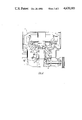
- FIG. 2 is a sectional elevation of a rock crusher, indicating the various locations where function-specific trace elements would be placed;
- FIG. 3a is a sectional elevation of a bearing from a machine embodying the present invention wherein the machine condition indicator is uniformly distributed throughout the bearing;
- FIG. 3b is a sectional elevation of a bearing from a machine embodying the present invention wherein the machine condition indicator is a trace element pill embedded in the bearing wall;
- FIG. 3c is a sectional elevation of a bearing from a machine embodying the present invention wherein the machine condition indicator is one of several laminated layers which comprise the bearing.
- a machine bearing condition diagnostic system comprising a machine 10 having an internal lubrication system and a machine condition monitoring system 12 which is capable of either periodically or continually monitoring machine vital signs such as component RPM, oil temperature, oil pressure, oil level in the oil holding tank, power draw and the time that various machine components continue moving after power to the machine has been cut off.
- machine vital signs such as component RPM, oil temperature, oil pressure, oil level in the oil holding tank, power draw and the time that various machine components continue moving after power to the machine has been cut off.
- the present system can also be used with existing devices capable of sensing a change in the dielectric constant of the lubricant, in this case lubricating oil.
- This dielectric analysis is applicable to the present invention because it provides the capability of sensing the presence of location-specific metallic trace elements in the lubricating oil. As the level of metallic particles carried in the oil varies, the conductivity changes. This change in conductivity is measured and compared with a predetermined value.
- the machine 10 to be monitored is fitted with components such as bearings within which trace element indicators 60 have been uniformly distributed (see FIG. 3a).
- the indicator materials comprise on the order of 1% of component mass.
- the indicators may be added to the bearing material during the casting process.
- Preferred indicators for bronze or brass bearings include but are not restricted to aluminum, beryllium, bismuth, carbon, cobalt, chromium and zirconium.
- indicators may be any traceable element or compound which can be uniformly distributed within a bearing without affecting its performance. Radioactive indicators may also be used.
- a rock crusher 10 embodying the present invention would have distinct indicator elements distributed in a function-specific arrangement.
- the socket liner 42 would be labelled with beryllium as its indicator, head bushing 44 with bismuth, eccentric bushing 46 with cobalt, and thrustplate bearing 48 with zirconium.
- distinct indicator elements could be assigned to designated classes of components, such as labelling all countershaft bushings 50 with chromium. Replacement bearings would contain the same indicator materials to assure continuity of the system.
- the alarm component 14 of the present invention is designed to be triggered by unacceptable variations in the amount of indicator metal present in the lubricating oil.
- an alternative embodiment of the present invention would involve the substitution of uniformly distributed trace element indicators in each bearing with the drilling of a bore 32 into the race surface of each bearing to beyond the depth of the maximum acceptable wear, which is usually in the range of about 1/16th of an inch.
- a pill 34 comprised of an indicator material is securely placed into the bottom of the bore.
- the pill may alternately be inserted into the bearing through the race area 38 or from the exterior 40.
- the bore 32 is then sealed up with a sealant 33 such as lead.
- the sealant need not match the wear properties of the bearing material because the amount of bearing-shaft contact is significantly greater than the cross-sectional area of the bore 32, and the bore area will not be subjected to extraordinary amounts of wear.
- the pill will be uncovered, releasing the indicator into the oil.
- a plurality of indicator pills may be located around the inner periphery of the bearing.
- the bearing may also be manufactured in laminar fashion with the indicator material 60 restricted to a separate layer which is exposed whenever wear exceeds acceptable limits.
- All of the above-mentioned monitored machine functions such as oil pressure and temperature, shaft RPM, power draw or dielectric constant have pre-set acceptable parameters within which the machine normally operates. If any of the monitors detect an unacceptable variation in any of the pre-set parameters, the system is designed to alert the operator by means of an alarm 14 in the form of a written printout, an audible signal such as a bell, or a flashing light.
- lubricant 16 In conventional systems, once the alarm is triggered, the operator only knows that a malfunction has been detected. In the present invention, once alarm 14 is triggered and a bearing failure is suspected, the operator removes a sample of the lubricant 16. The amount of lubricant in the sample will vary from machine to machine; however, anywhere from one pint to one quart will be acceptable. In the case of machines not fitted with automatic vital sign monitoring systems, lubricant can still be sampled on a periodic basis as a preventive measure.
- the sample then undergoes analysis, 18 such as by spectrochemical means, to determine the identity of various contaminants contained therein.
- analysis such as by spectrochemical means
- the type of analytical method will vary with the individual characteristics of the various indicator elements.
- the analysis will reveal the presence of excessive amounts of trace elements corresponding to one or more locations in the machine where excessive bearing wear is occurring.
- the operator merely has to coordinate the material found in the analysis with the functional section of the machine associated with that particular indicator. Appropriate repair and/or replacement of malfunctioning parts 20 can then be readily accomplished, in many instances avoiding catastrophic failure and minimizing downtime and failure cost.
- the machine operator will then remove a sample of lubricant and have it analyzed via spectrochemical or other means. The results of the analysis will identify and quantify the various indicator contaminants. Those indicators whose levels deviate from predetermined values will be noted and correlated with their corresponding machine function to identify the malfunctioning component or components.
- the present invention provides a machine condition diagnostic system which is capable of monitoring the condition of lubricant and pinpointing malfunctioning components so that machine down time is minimized and repairs are accomplished more efficiently. While a particular embodiment of this process has been described, it will be obvious to persons skilled in the art that changes and modifications might be made without departing from the invention in its broader aspects. It is the aim of the dependent claims to cover all such changes and modifications as fall within the true scope and spirit of the invention.
Abstract
Description
Claims (12)
Priority Applications (8)
| Application Number | Priority Date | Filing Date | Title |
|---|---|---|---|
| US06/721,097 US4620185A (en) | 1985-04-08 | 1985-04-08 | Wearing part diagnostic system employing tracer elements |
| AU54662/86A AU5466286A (en) | 1985-04-08 | 1986-03-12 | Machine condition diagnostic system |
| ZA862030A ZA862030B (en) | 1985-04-08 | 1986-03-19 | Machine condition diagnostic system |
| KR1019860002311A KR860007962A (en) | 1985-04-08 | 1986-03-28 | Machine Condition Diagnosis System and Bearing Condition Remote Detection Method |
| EP86630054A EP0197878A3 (en) | 1985-04-08 | 1986-04-03 | Machine condition diagnostic system |
| BR8601573A BR8601573A (en) | 1985-04-08 | 1986-04-07 | PROCESS TO MONITOR A MACHINE WITH AN INTERNAL LUBRICATION SYSTEM AND PROCESS TO MONITOR THE CONDITION OF THE BEARING LUBRICANT |
| JP61079357A JPS6258133A (en) | 1985-04-08 | 1986-04-08 | Diagnostic system of state of machine |
| US06/882,324 US4658638A (en) | 1985-04-08 | 1986-07-07 | Machine component diagnostic system |
Applications Claiming Priority (1)
| Application Number | Priority Date | Filing Date | Title |
|---|---|---|---|
| US06/721,097 US4620185A (en) | 1985-04-08 | 1985-04-08 | Wearing part diagnostic system employing tracer elements |
Related Child Applications (1)
| Application Number | Title | Priority Date | Filing Date |
|---|---|---|---|
| US06/882,324 Continuation-In-Part US4658638A (en) | 1985-04-08 | 1986-07-07 | Machine component diagnostic system |
Publications (1)
| Publication Number | Publication Date |
|---|---|
| US4620185A true US4620185A (en) | 1986-10-28 |
Family
ID=24896524
Family Applications (1)
| Application Number | Title | Priority Date | Filing Date |
|---|---|---|---|
| US06/721,097 Expired - Fee Related US4620185A (en) | 1985-04-08 | 1985-04-08 | Wearing part diagnostic system employing tracer elements |
Country Status (7)
| Country | Link |
|---|---|
| US (1) | US4620185A (en) |
| EP (1) | EP0197878A3 (en) |
| JP (1) | JPS6258133A (en) |
| KR (1) | KR860007962A (en) |
| AU (1) | AU5466286A (en) |
| BR (1) | BR8601573A (en) |
| ZA (1) | ZA862030B (en) |
Cited By (24)
| Publication number | Priority date | Publication date | Assignee | Title |
|---|---|---|---|---|
| US4909081A (en) * | 1988-02-03 | 1990-03-20 | Schlumberger Industries Limited | Systems for detecting magnetic particles in fluids |
| US5061364A (en) * | 1990-01-26 | 1991-10-29 | Westinghouse Electric Corp. | Diagnostic filter for detecting conductive and semiconductive particles in a fluid stream |
| US5187542A (en) * | 1991-06-27 | 1993-02-16 | The United States Of America As Represented By The Administrator Of The National Aeronautics And Space Administration | Spectroscopic wear detector |
| US5473643A (en) * | 1994-08-19 | 1995-12-05 | Westinghouse Idaho Nuclear Company | Corrosion testing using isotopes |
| US5602945A (en) * | 1996-03-21 | 1997-02-11 | Nordberg, Incorporated | Thrust bearing for use in a conical crusher |
| US5769339A (en) * | 1996-11-22 | 1998-06-23 | Nordberg, Inc. | Conical gyratory mill for fine or regrinding |
| US5799885A (en) * | 1996-11-22 | 1998-09-01 | Nordberg, Inc. | High reduction ratio crushing in conical/gyratory crushers |
| US5806772A (en) * | 1996-11-22 | 1998-09-15 | Nordberg, Inc. | Conical gyratory grinding and crushing apparatus |
| EP0982579A1 (en) * | 1998-03-16 | 2000-03-01 | Central Japan Railway Company | Devices for inspecting bearings of main motors of rolling stock |
| US6065698A (en) * | 1996-11-22 | 2000-05-23 | Nordberg Incorporated | Anti-spin method and apparatus for conical/gyratory crushers |
| US6510726B1 (en) * | 1998-12-23 | 2003-01-28 | Federal-Mogul World Wide, Inc. | Bismuth tracer bearings |
| US6637932B2 (en) * | 1999-09-17 | 2003-10-28 | General Electric Company | Engine thrust bearing condition monitoring method |
| US6680688B1 (en) * | 2002-12-09 | 2004-01-20 | Viewmove Technologies, Inc. | Measuring system and method for detecting object distance by transmitted media with different wave velocities |
| US6746154B2 (en) | 2001-10-08 | 2004-06-08 | Federal-Mogul World Wide, Inc. | Lead-free bearing |
| DE10340489A1 (en) * | 2003-09-03 | 2005-03-31 | ThyssenKrupp Fördertechnik GmbH | Mineral mill bearing wear monitoring procedure uses pairs of trace element inclusions on surface layers to allow detection in lubricant |
| US20060067465A1 (en) * | 2004-09-24 | 2006-03-30 | Bary Wilson | Component specific machine wear determination with x-ray fluorescence spectrometry |
| DE102005009512B3 (en) * | 2005-02-24 | 2006-04-20 | Federal-Mogul Wiesbaden Gmbh & Co. Kg | Test rig, for checking adhesion of bearing metal layers on plain bearings, has two housing parts with play that can put stress on bearing |
| US20080237381A1 (en) * | 2007-03-27 | 2008-10-02 | Dennis Kruger | Pill crusher and pill pouch |
| US20170284914A1 (en) * | 2016-04-01 | 2017-10-05 | Caterpillar Inc. | Additive manufactured component that indicates wear and system and method thereof |
| US10180075B1 (en) * | 2017-08-25 | 2019-01-15 | Rolls-Royce Corporation | On-wing component wear analysis with fluid quality sensing |
| US10634583B2 (en) | 2015-07-09 | 2020-04-28 | Mhwirth As | Condition monitoring method |
| US11175274B2 (en) * | 2019-06-03 | 2021-11-16 | Caterpillar Inc. | Systems and methods for remaining useful life prediction of a fluid |
| DE102020215637A1 (en) | 2020-12-10 | 2022-06-15 | Robert Bosch Gesellschaft mit beschränkter Haftung | Method of making a three-dimensional object |
| EP4036550A4 (en) * | 2019-09-27 | 2023-10-18 | Daido Metal Company Ltd. | Sliding member of internal combustion engine including self-detecting material for monitoring sliding member damage |
Families Citing this family (5)
| Publication number | Priority date | Publication date | Assignee | Title |
|---|---|---|---|---|
| AU577689B2 (en) * | 1985-05-23 | 1988-09-29 | Hamersley Iron Pty. Limited | Detecting the degree of wear of a lubricated machine component. |
| GB8802237D0 (en) * | 1988-02-02 | 1988-03-02 | Shell Int Research | Detection of chemicals by immunoassay |
| JP2730184B2 (en) * | 1989-05-30 | 1998-03-25 | 石川島播磨重工業株式会社 | Diagnosis method for paper machine dryer lubrication |
| NO339758B1 (en) * | 2016-02-11 | 2017-01-30 | Mhwirth As | Condition monitoring method |
| GB2602038A (en) * | 2020-12-16 | 2022-06-22 | Edwards Ltd | Bearing wear monitoring |
Citations (9)
| Publication number | Priority date | Publication date | Assignee | Title |
|---|---|---|---|---|
| US2315845A (en) * | 1941-10-25 | 1943-04-06 | Atlantic Refining Co | Wear test method and composition |
| US2808563A (en) * | 1954-06-08 | 1957-10-01 | Beloit Iron Works | Film strength tester |
| US2939011A (en) * | 1954-07-01 | 1960-05-31 | Tidewater Oil Company | Wear test method and apparatus |
| US3228735A (en) * | 1961-03-07 | 1966-01-11 | John T Stewart | Damage indicators for car axle bearings |
| US3678883A (en) * | 1970-03-25 | 1972-07-25 | Smith International | Worn bearing indicator |
| US4029554A (en) * | 1974-05-20 | 1977-06-14 | Naeco Associates, Inc. | Oil test method |
| US4169677A (en) * | 1976-05-03 | 1979-10-02 | Panel Laboratories Ltd. | Method and apparatus for diagnosing the condition of oil-wetted parts |
| US4364032A (en) * | 1979-12-08 | 1982-12-14 | Hitachi, Ltd. | Method and apparatus for diagnosing local overheating in a rotary electric machine |
| US4492461A (en) * | 1981-03-19 | 1985-01-08 | Jones David G | Wear analysis equipment |
Family Cites Families (3)
| Publication number | Priority date | Publication date | Assignee | Title |
|---|---|---|---|---|
| DE2313998A1 (en) * | 1973-03-21 | 1974-09-26 | Heinz Dr Rupp | SIMPLE METHOD FOR CHECKING THE QUALITY OF MACHINE OILS OR OTHER LUBRICANTS DURING OPERATION |
| DE2710343C2 (en) * | 1977-03-10 | 1979-04-12 | Klein, Schanzlin & Becker Ag, 6710 Frankenthal | Wear indicator for shaft bearings |
| US4203725A (en) * | 1978-02-13 | 1980-05-20 | Contamoil Corporation | Method and test kit for the on-site determination of the presence of contaminant material in lubricating oil |
-
1985
- 1985-04-08 US US06/721,097 patent/US4620185A/en not_active Expired - Fee Related
-
1986
- 1986-03-12 AU AU54662/86A patent/AU5466286A/en not_active Abandoned
- 1986-03-19 ZA ZA862030A patent/ZA862030B/en unknown
- 1986-03-28 KR KR1019860002311A patent/KR860007962A/en not_active Application Discontinuation
- 1986-04-03 EP EP86630054A patent/EP0197878A3/en not_active Withdrawn
- 1986-04-07 BR BR8601573A patent/BR8601573A/en unknown
- 1986-04-08 JP JP61079357A patent/JPS6258133A/en active Pending
Patent Citations (9)
| Publication number | Priority date | Publication date | Assignee | Title |
|---|---|---|---|---|
| US2315845A (en) * | 1941-10-25 | 1943-04-06 | Atlantic Refining Co | Wear test method and composition |
| US2808563A (en) * | 1954-06-08 | 1957-10-01 | Beloit Iron Works | Film strength tester |
| US2939011A (en) * | 1954-07-01 | 1960-05-31 | Tidewater Oil Company | Wear test method and apparatus |
| US3228735A (en) * | 1961-03-07 | 1966-01-11 | John T Stewart | Damage indicators for car axle bearings |
| US3678883A (en) * | 1970-03-25 | 1972-07-25 | Smith International | Worn bearing indicator |
| US4029554A (en) * | 1974-05-20 | 1977-06-14 | Naeco Associates, Inc. | Oil test method |
| US4169677A (en) * | 1976-05-03 | 1979-10-02 | Panel Laboratories Ltd. | Method and apparatus for diagnosing the condition of oil-wetted parts |
| US4364032A (en) * | 1979-12-08 | 1982-12-14 | Hitachi, Ltd. | Method and apparatus for diagnosing local overheating in a rotary electric machine |
| US4492461A (en) * | 1981-03-19 | 1985-01-08 | Jones David G | Wear analysis equipment |
Cited By (31)
| Publication number | Priority date | Publication date | Assignee | Title |
|---|---|---|---|---|
| US4909081A (en) * | 1988-02-03 | 1990-03-20 | Schlumberger Industries Limited | Systems for detecting magnetic particles in fluids |
| US5061364A (en) * | 1990-01-26 | 1991-10-29 | Westinghouse Electric Corp. | Diagnostic filter for detecting conductive and semiconductive particles in a fluid stream |
| US5187542A (en) * | 1991-06-27 | 1993-02-16 | The United States Of America As Represented By The Administrator Of The National Aeronautics And Space Administration | Spectroscopic wear detector |
| US5473643A (en) * | 1994-08-19 | 1995-12-05 | Westinghouse Idaho Nuclear Company | Corrosion testing using isotopes |
| US5602945A (en) * | 1996-03-21 | 1997-02-11 | Nordberg, Incorporated | Thrust bearing for use in a conical crusher |
| US5799885A (en) * | 1996-11-22 | 1998-09-01 | Nordberg, Inc. | High reduction ratio crushing in conical/gyratory crushers |
| US5769339A (en) * | 1996-11-22 | 1998-06-23 | Nordberg, Inc. | Conical gyratory mill for fine or regrinding |
| US5806772A (en) * | 1996-11-22 | 1998-09-15 | Nordberg, Inc. | Conical gyratory grinding and crushing apparatus |
| US6065698A (en) * | 1996-11-22 | 2000-05-23 | Nordberg Incorporated | Anti-spin method and apparatus for conical/gyratory crushers |
| US6315225B1 (en) | 1996-11-22 | 2001-11-13 | Metso Minerals (Milwaukee) Inc. | Anti-spin method and apparatus for conical/gyratory crushers |
| EP0982579A1 (en) * | 1998-03-16 | 2000-03-01 | Central Japan Railway Company | Devices for inspecting bearings of main motors of rolling stock |
| EP0982579A4 (en) * | 1998-03-16 | 2006-03-22 | Tokai Ryokaku Tetsudo Kk | Devices for inspecting bearings of main motors of rolling stock |
| US6510726B1 (en) * | 1998-12-23 | 2003-01-28 | Federal-Mogul World Wide, Inc. | Bismuth tracer bearings |
| US6637932B2 (en) * | 1999-09-17 | 2003-10-28 | General Electric Company | Engine thrust bearing condition monitoring method |
| US6746154B2 (en) | 2001-10-08 | 2004-06-08 | Federal-Mogul World Wide, Inc. | Lead-free bearing |
| US20040111892A1 (en) * | 2001-10-08 | 2004-06-17 | Greene Robert L. | Lead-free bearing |
| US6854183B2 (en) | 2001-10-08 | 2005-02-15 | Federal-Mogul World Wide, Inc. | Lead-free bearing |
| US6680688B1 (en) * | 2002-12-09 | 2004-01-20 | Viewmove Technologies, Inc. | Measuring system and method for detecting object distance by transmitted media with different wave velocities |
| DE10340489A1 (en) * | 2003-09-03 | 2005-03-31 | ThyssenKrupp Fördertechnik GmbH | Mineral mill bearing wear monitoring procedure uses pairs of trace element inclusions on surface layers to allow detection in lubricant |
| US20060067465A1 (en) * | 2004-09-24 | 2006-03-30 | Bary Wilson | Component specific machine wear determination with x-ray fluorescence spectrometry |
| US7184515B2 (en) * | 2004-09-24 | 2007-02-27 | Battelle Memorial Institute | Component specific machine wear determination with x-ray fluorescence spectrometry |
| DE102005009512B3 (en) * | 2005-02-24 | 2006-04-20 | Federal-Mogul Wiesbaden Gmbh & Co. Kg | Test rig, for checking adhesion of bearing metal layers on plain bearings, has two housing parts with play that can put stress on bearing |
| US7648093B2 (en) | 2007-03-27 | 2010-01-19 | Dennis Kruger | Pill crusher and pill pouch |
| US20080237381A1 (en) * | 2007-03-27 | 2008-10-02 | Dennis Kruger | Pill crusher and pill pouch |
| US10634583B2 (en) | 2015-07-09 | 2020-04-28 | Mhwirth As | Condition monitoring method |
| US20170284914A1 (en) * | 2016-04-01 | 2017-10-05 | Caterpillar Inc. | Additive manufactured component that indicates wear and system and method thereof |
| US10267718B2 (en) * | 2016-04-01 | 2019-04-23 | Caterpillar Inc. | Additive manufactured component that indicates wear and system and method thereof |
| US10180075B1 (en) * | 2017-08-25 | 2019-01-15 | Rolls-Royce Corporation | On-wing component wear analysis with fluid quality sensing |
| US11175274B2 (en) * | 2019-06-03 | 2021-11-16 | Caterpillar Inc. | Systems and methods for remaining useful life prediction of a fluid |
| EP4036550A4 (en) * | 2019-09-27 | 2023-10-18 | Daido Metal Company Ltd. | Sliding member of internal combustion engine including self-detecting material for monitoring sliding member damage |
| DE102020215637A1 (en) | 2020-12-10 | 2022-06-15 | Robert Bosch Gesellschaft mit beschränkter Haftung | Method of making a three-dimensional object |
Also Published As
| Publication number | Publication date |
|---|---|
| KR860007962A (en) | 1986-11-10 |
| EP0197878A2 (en) | 1986-10-15 |
| AU5466286A (en) | 1986-10-16 |
| JPS6258133A (en) | 1987-03-13 |
| BR8601573A (en) | 1986-12-09 |
| ZA862030B (en) | 1986-11-26 |
| EP0197878A3 (en) | 1987-01-07 |
Similar Documents
| Publication | Publication Date | Title |
|---|---|---|
| US4620185A (en) | Wearing part diagnostic system employing tracer elements | |
| US4658638A (en) | Machine component diagnostic system | |
| EP1549942B1 (en) | Fluid condition monitor | |
| JP7099816B2 (en) | Lubricating oil deterioration diagnostic method, lubricating oil monitoring system and method for rotating machinery | |
| KR20150004844A (en) | Bearing monitoring method and system | |
| EP3964703A1 (en) | Engine lubrication oil consumption and condition monitoring | |
| JP5990729B1 (en) | General-purpose deterioration curve creation method and machine life prediction method, and general-purpose deterioration curve creation program and machine life prediction program | |
| Karanović et al. | Benefits of lubricant oil analysis for maintenance decision support: a case study | |
| TW202006248A (en) | Wind drive generator diagnostic system and method, and wind drive generator diagnostic device characterized by accurately and quickly determining whether there is a need for an analysis associated with the taking of lubricant oil and whether there is a need for maintenance work such as lubricant oil replacement, parts replacement, etc. | |
| US7184515B2 (en) | Component specific machine wear determination with x-ray fluorescence spectrometry | |
| JP6919986B2 (en) | Lubricating oil monitoring systems and methods for wind power generators | |
| CN113418731A (en) | Online fault diagnosis method for cigarette making machine set | |
| DE102011076099B4 (en) | Method for operating a bearing arrangement | |
| WO2018112598A1 (en) | A system and method for monitoring the status of an electric submersible pump | |
| US4651560A (en) | Methods of an apparatus for monitoring mechanical equipment's operational condition | |
| Scott | The application of ferrography to the condition monitoring of gas turbines | |
| KR19980053189A (en) | How to detect hot rolling mill chatter | |
| Whitby | What to monitor? | |
| Wang et al. | On-line oil monitoring sensors fusion for aircraft health management | |
| Sheldon et al. | Combining Oil Health, Level, and Vibration to Achieve Complete Machine Monitoring | |
| CA1038358A (en) | Protective device for a roller type pulverizer | |
| JP2016098996A (en) | Lubricant deterioration detection method and rolling device with lubricant deterioration detection means | |
| Baker et al. | Failure modes and prognostic techniques for h-60 tail rotor drive system bearings | |
| Parikka et al. | Towards adaptive grease lubrication | |
| Woodley | Failure prediction by condition monitoring (part 1) |
Legal Events
| Date | Code | Title | Description |
|---|---|---|---|
| AS | Assignment |
Owner name: REXNORD INC., A WI CORP Free format text: ASSIGNMENT OF ASSIGNORS INTEREST.;ASSIGNOR:PLAHMER, THOMAS G.;REEL/FRAME:004394/0281 Effective date: 19850404 |
|
| AS | Assignment |
Owner name: NORDBERG INC., 3073 S. CHASE AVE., MILWAUKEE, WI 5 Free format text: ASSIGNMENT OF ASSIGNORS INTEREST.;ASSIGNOR:REXNORD INC.;REEL/FRAME:004834/0102 Effective date: 19880126 Owner name: NORDBERG INC., A CORP. OF DE,WISCONSIN Free format text: ASSIGNMENT OF ASSIGNORS INTEREST;ASSIGNOR:REXNORD INC.;REEL/FRAME:004834/0102 Effective date: 19880126 |
|
| AS | Assignment |
Owner name: FIRST NATIONAL BANK OF BOSTON, THE, 100 FEDERAL ST Free format text: SECURITY INTEREST;ASSIGNOR:NORDBERG, INC., A DE CORP.;REEL/FRAME:004930/0280 Effective date: 19880729 Owner name: FIRST NATIONAL BANK OF BOSTON, THE, MASSACHUSETTS Free format text: SECURITY INTEREST;ASSIGNOR:NORDBERG, INC., A DE CORP.;REEL/FRAME:004930/0280 Effective date: 19880729 |
|
| AS | Assignment |
Owner name: FIRST NATIONAL BANK OF BOSTON, THE, 100 FEDERAL ST Free format text: RELEASED BY SECURED PARTY;ASSIGNOR:NORDBERG, INC., 3073 SOUTH CHASE AVE., MILWAUKEE, WI 53207, A DE CORP.;REEL/FRAME:005060/0994 Effective date: 19890308 |
|
| FEPP | Fee payment procedure |
Free format text: PAYOR NUMBER ASSIGNED (ORIGINAL EVENT CODE: ASPN); ENTITY STATUS OF PATENT OWNER: LARGE ENTITY |
|
| FPAY | Fee payment |
Year of fee payment: 4 |
|
| FPAY | Fee payment |
Year of fee payment: 8 |
|
| REMI | Maintenance fee reminder mailed | ||
| LAPS | Lapse for failure to pay maintenance fees | ||
| FP | Lapsed due to failure to pay maintenance fee |
Effective date: 19981028 |
|
| STCH | Information on status: patent discontinuation |
Free format text: PATENT EXPIRED DUE TO NONPAYMENT OF MAINTENANCE FEES UNDER 37 CFR 1.362 |