EP4137769A1 - Display device and refrigerator having the same - Google Patents
Display device and refrigerator having the same Download PDFInfo
- Publication number
- EP4137769A1 EP4137769A1 EP22194183.4A EP22194183A EP4137769A1 EP 4137769 A1 EP4137769 A1 EP 4137769A1 EP 22194183 A EP22194183 A EP 22194183A EP 4137769 A1 EP4137769 A1 EP 4137769A1
- Authority
- EP
- European Patent Office
- Prior art keywords
- refrigerator
- storage
- displayed
- icon
- button
- Prior art date
- Legal status (The legal status is an assumption and is not a legal conclusion. Google has not performed a legal analysis and makes no representation as to the accuracy of the status listed.)
- Pending
Links
- 230000015654 memory Effects 0.000 claims abstract description 27
- 230000008014 freezing Effects 0.000 claims description 88
- 238000007710 freezing Methods 0.000 claims description 88
- 230000008859 change Effects 0.000 claims description 25
- 238000004891 communication Methods 0.000 abstract description 19
- 238000007726 management method Methods 0.000 description 58
- 238000000034 method Methods 0.000 description 53
- 235000013305 food Nutrition 0.000 description 43
- 239000000463 material Substances 0.000 description 33
- 230000006870 function Effects 0.000 description 25
- 230000008569 process Effects 0.000 description 24
- 238000012790 confirmation Methods 0.000 description 18
- 238000003780 insertion Methods 0.000 description 17
- 230000037431 insertion Effects 0.000 description 17
- 238000012217 deletion Methods 0.000 description 16
- 230000037430 deletion Effects 0.000 description 16
- 238000003745 diagnosis Methods 0.000 description 15
- 241000287828 Gallus gallus Species 0.000 description 10
- 230000002354 daily effect Effects 0.000 description 10
- 238000010411 cooking Methods 0.000 description 9
- 230000005236 sound signal Effects 0.000 description 9
- 230000003442 weekly effect Effects 0.000 description 8
- 230000000007 visual effect Effects 0.000 description 7
- 244000061456 Solanum tuberosum Species 0.000 description 5
- 235000002595 Solanum tuberosum Nutrition 0.000 description 5
- 235000013527 bean curd Nutrition 0.000 description 5
- 235000013399 edible fruits Nutrition 0.000 description 5
- 230000001954 sterilising effect Effects 0.000 description 5
- 230000001965 increasing effect Effects 0.000 description 4
- 235000011888 snacks Nutrition 0.000 description 4
- 238000004659 sterilization and disinfection Methods 0.000 description 4
- 241000894006 Bacteria Species 0.000 description 3
- 230000005540 biological transmission Effects 0.000 description 3
- 235000013372 meat Nutrition 0.000 description 3
- 238000010295 mobile communication Methods 0.000 description 3
- 238000012545 processing Methods 0.000 description 3
- 241000251468 Actinopterygii Species 0.000 description 2
- 240000002234 Allium sativum Species 0.000 description 2
- 244000088415 Raphanus sativus Species 0.000 description 2
- 235000006140 Raphanus sativus var sativus Nutrition 0.000 description 2
- 238000006243 chemical reaction Methods 0.000 description 2
- 239000003086 colorant Substances 0.000 description 2
- 230000003247 decreasing effect Effects 0.000 description 2
- 238000010586 diagram Methods 0.000 description 2
- 235000004611 garlic Nutrition 0.000 description 2
- 235000021109 kimchi Nutrition 0.000 description 2
- 239000004973 liquid crystal related substance Substances 0.000 description 2
- 238000012986 modification Methods 0.000 description 2
- 230000004048 modification Effects 0.000 description 2
- 235000019645 odor Nutrition 0.000 description 2
- 230000003287 optical effect Effects 0.000 description 2
- 238000002360 preparation method Methods 0.000 description 2
- 238000004171 remote diagnosis Methods 0.000 description 2
- 230000003068 static effect Effects 0.000 description 2
- 235000005979 Citrus limon Nutrition 0.000 description 1
- 244000131522 Citrus pyriformis Species 0.000 description 1
- 240000008415 Lactuca sativa Species 0.000 description 1
- 241000700605 Viruses Species 0.000 description 1
- 230000004308 accommodation Effects 0.000 description 1
- 230000003213 activating effect Effects 0.000 description 1
- 238000003491 array Methods 0.000 description 1
- 230000002457 bidirectional effect Effects 0.000 description 1
- 230000001413 cellular effect Effects 0.000 description 1
- 239000012141 concentrate Substances 0.000 description 1
- 238000013500 data storage Methods 0.000 description 1
- 238000004332 deodorization Methods 0.000 description 1
- 230000000694 effects Effects 0.000 description 1
- 230000005611 electricity Effects 0.000 description 1
- 230000003203 everyday effect Effects 0.000 description 1
- 239000010408 film Substances 0.000 description 1
- 238000005286 illumination Methods 0.000 description 1
- 230000001939 inductive effect Effects 0.000 description 1
- 238000003825 pressing Methods 0.000 description 1
- 235000012045 salad Nutrition 0.000 description 1
- 239000000126 substance Substances 0.000 description 1
- 230000001360 synchronised effect Effects 0.000 description 1
- 238000012360 testing method Methods 0.000 description 1
- 239000010409 thin film Substances 0.000 description 1
Images


Classifications
-
- F—MECHANICAL ENGINEERING; LIGHTING; HEATING; WEAPONS; BLASTING
- F25—REFRIGERATION OR COOLING; COMBINED HEATING AND REFRIGERATION SYSTEMS; HEAT PUMP SYSTEMS; MANUFACTURE OR STORAGE OF ICE; LIQUEFACTION SOLIDIFICATION OF GASES
- F25D—REFRIGERATORS; COLD ROOMS; ICE-BOXES; COOLING OR FREEZING APPARATUS NOT OTHERWISE PROVIDED FOR
- F25D29/00—Arrangement or mounting of control or safety devices
- F25D29/005—Mounting of control devices
-
- F—MECHANICAL ENGINEERING; LIGHTING; HEATING; WEAPONS; BLASTING
- F25—REFRIGERATION OR COOLING; COMBINED HEATING AND REFRIGERATION SYSTEMS; HEAT PUMP SYSTEMS; MANUFACTURE OR STORAGE OF ICE; LIQUEFACTION SOLIDIFICATION OF GASES
- F25D—REFRIGERATORS; COLD ROOMS; ICE-BOXES; COOLING OR FREEZING APPARATUS NOT OTHERWISE PROVIDED FOR
- F25D11/00—Self-contained movable devices, e.g. domestic refrigerators
- F25D11/02—Self-contained movable devices, e.g. domestic refrigerators with cooling compartments at different temperatures
-
- F—MECHANICAL ENGINEERING; LIGHTING; HEATING; WEAPONS; BLASTING
- F25—REFRIGERATION OR COOLING; COMBINED HEATING AND REFRIGERATION SYSTEMS; HEAT PUMP SYSTEMS; MANUFACTURE OR STORAGE OF ICE; LIQUEFACTION SOLIDIFICATION OF GASES
- F25D—REFRIGERATORS; COLD ROOMS; ICE-BOXES; COOLING OR FREEZING APPARATUS NOT OTHERWISE PROVIDED FOR
- F25D23/00—General constructional features
- F25D23/02—Doors; Covers
- F25D23/028—Details
-
- F—MECHANICAL ENGINEERING; LIGHTING; HEATING; WEAPONS; BLASTING
- F25—REFRIGERATION OR COOLING; COMBINED HEATING AND REFRIGERATION SYSTEMS; HEAT PUMP SYSTEMS; MANUFACTURE OR STORAGE OF ICE; LIQUEFACTION SOLIDIFICATION OF GASES
- F25D—REFRIGERATORS; COLD ROOMS; ICE-BOXES; COOLING OR FREEZING APPARATUS NOT OTHERWISE PROVIDED FOR
- F25D29/00—Arrangement or mounting of control or safety devices
-
- G—PHYSICS
- G06—COMPUTING; CALCULATING OR COUNTING
- G06F—ELECTRIC DIGITAL DATA PROCESSING
- G06F3/00—Input arrangements for transferring data to be processed into a form capable of being handled by the computer; Output arrangements for transferring data from processing unit to output unit, e.g. interface arrangements
- G06F3/01—Input arrangements or combined input and output arrangements for interaction between user and computer
- G06F3/048—Interaction techniques based on graphical user interfaces [GUI]
- G06F3/0481—Interaction techniques based on graphical user interfaces [GUI] based on specific properties of the displayed interaction object or a metaphor-based environment, e.g. interaction with desktop elements like windows or icons, or assisted by a cursor's changing behaviour or appearance
- G06F3/0482—Interaction with lists of selectable items, e.g. menus
-
- G—PHYSICS
- G06—COMPUTING; CALCULATING OR COUNTING
- G06F—ELECTRIC DIGITAL DATA PROCESSING
- G06F3/00—Input arrangements for transferring data to be processed into a form capable of being handled by the computer; Output arrangements for transferring data from processing unit to output unit, e.g. interface arrangements
- G06F3/01—Input arrangements or combined input and output arrangements for interaction between user and computer
- G06F3/048—Interaction techniques based on graphical user interfaces [GUI]
- G06F3/0484—Interaction techniques based on graphical user interfaces [GUI] for the control of specific functions or operations, e.g. selecting or manipulating an object, an image or a displayed text element, setting a parameter value or selecting a range
- G06F3/04847—Interaction techniques to control parameter settings, e.g. interaction with sliders or dials
-
- G—PHYSICS
- G06—COMPUTING; CALCULATING OR COUNTING
- G06F—ELECTRIC DIGITAL DATA PROCESSING
- G06F3/00—Input arrangements for transferring data to be processed into a form capable of being handled by the computer; Output arrangements for transferring data from processing unit to output unit, e.g. interface arrangements
- G06F3/01—Input arrangements or combined input and output arrangements for interaction between user and computer
- G06F3/048—Interaction techniques based on graphical user interfaces [GUI]
- G06F3/0484—Interaction techniques based on graphical user interfaces [GUI] for the control of specific functions or operations, e.g. selecting or manipulating an object, an image or a displayed text element, setting a parameter value or selecting a range
- G06F3/0486—Drag-and-drop
-
- G—PHYSICS
- G06—COMPUTING; CALCULATING OR COUNTING
- G06F—ELECTRIC DIGITAL DATA PROCESSING
- G06F3/00—Input arrangements for transferring data to be processed into a form capable of being handled by the computer; Output arrangements for transferring data from processing unit to output unit, e.g. interface arrangements
- G06F3/01—Input arrangements or combined input and output arrangements for interaction between user and computer
- G06F3/048—Interaction techniques based on graphical user interfaces [GUI]
- G06F3/0487—Interaction techniques based on graphical user interfaces [GUI] using specific features provided by the input device, e.g. functions controlled by the rotation of a mouse with dual sensing arrangements, or of the nature of the input device, e.g. tap gestures based on pressure sensed by a digitiser
- G06F3/0488—Interaction techniques based on graphical user interfaces [GUI] using specific features provided by the input device, e.g. functions controlled by the rotation of a mouse with dual sensing arrangements, or of the nature of the input device, e.g. tap gestures based on pressure sensed by a digitiser using a touch-screen or digitiser, e.g. input of commands through traced gestures
- G06F3/04886—Interaction techniques based on graphical user interfaces [GUI] using specific features provided by the input device, e.g. functions controlled by the rotation of a mouse with dual sensing arrangements, or of the nature of the input device, e.g. tap gestures based on pressure sensed by a digitiser using a touch-screen or digitiser, e.g. input of commands through traced gestures by partitioning the display area of the touch-screen or the surface of the digitising tablet into independently controllable areas, e.g. virtual keyboards or menus
-
- F—MECHANICAL ENGINEERING; LIGHTING; HEATING; WEAPONS; BLASTING
- F25—REFRIGERATION OR COOLING; COMBINED HEATING AND REFRIGERATION SYSTEMS; HEAT PUMP SYSTEMS; MANUFACTURE OR STORAGE OF ICE; LIQUEFACTION SOLIDIFICATION OF GASES
- F25D—REFRIGERATORS; COLD ROOMS; ICE-BOXES; COOLING OR FREEZING APPARATUS NOT OTHERWISE PROVIDED FOR
- F25D2400/00—General features of, or devices for refrigerators, cold rooms, ice-boxes, or for cooling or freezing apparatus not covered by any other subclass
- F25D2400/36—Visual displays
- F25D2400/361—Interactive visual displays
-
- F—MECHANICAL ENGINEERING; LIGHTING; HEATING; WEAPONS; BLASTING
- F25—REFRIGERATION OR COOLING; COMBINED HEATING AND REFRIGERATION SYSTEMS; HEAT PUMP SYSTEMS; MANUFACTURE OR STORAGE OF ICE; LIQUEFACTION SOLIDIFICATION OF GASES
- F25D—REFRIGERATORS; COLD ROOMS; ICE-BOXES; COOLING OR FREEZING APPARATUS NOT OTHERWISE PROVIDED FOR
- F25D2500/00—Problems to be solved
- F25D2500/06—Stock management
-
- F—MECHANICAL ENGINEERING; LIGHTING; HEATING; WEAPONS; BLASTING
- F25—REFRIGERATION OR COOLING; COMBINED HEATING AND REFRIGERATION SYSTEMS; HEAT PUMP SYSTEMS; MANUFACTURE OR STORAGE OF ICE; LIQUEFACTION SOLIDIFICATION OF GASES
- F25D—REFRIGERATORS; COLD ROOMS; ICE-BOXES; COOLING OR FREEZING APPARATUS NOT OTHERWISE PROVIDED FOR
- F25D2700/00—Means for sensing or measuring; Sensors therefor
- F25D2700/06—Sensors detecting the presence of a product
Definitions
- the present invention relates to a display device and a refrigerator having the same, and more particularly, to a refrigerator which is communicable with a refrigerator main body and a communication device.
- a refrigerator is an electric home appliance which stores food and other items in a cold state or a frozen state using a refrigerating cycle, and includes a main body provided with storage chambers and doors provided on the main body to open and close the storage chambers, and compressors, condensers, expansion devices and evaporators are provided at the inside of the main body.
- a main purpose of the refrigerator is to keep the storage state of stored items without damage while remarkably increasing the storage period of the items.
- the present invention is directed to a display device and a refrigerator having the same that substantially obviate one or more problems due to limitations and disadvantages of the related art.
- An object of the present invention is to provide a refrigerator which may provide various pieces of information to users or process useful information.
- Another object of the present invention is to provide a refrigerator which may provide a convenient user interface to users.
- a refrigerator includes a display unit to display the inner shape of the refrigerator including a plurality of storage spaces, in a first area, a memory having storage information on stored items stored in each of the plurality of storage spaces, and a controller to display icons indicating at least one of kinds and the numbers of the stored items stored in each of the plurality of storage spaces of the inner shape of the refrigerator according to the storage information.
- a refrigerator in another aspect of the present invention, includes a main body including storage chambers to store items, doors to open and close the main body, a display device installed on one of the doors, and provided with an insertion slot into which a designated storage device is inserted and a display unit to visually display designated information, and a cover member detachably provided on the one of the doors to selectively cover one side surface of the display device provided with the insertion slot.
- a refrigerator in accordance with the present invention includes a main body 1 provided with storage chambers, and doors to open and close the storage chambers, and a display device 200 which may provide information to users or receive information is provided on one of the doors.
- the storage chambers include a freezing chamber 5 and a refrigerating chamber 6.
- FIG. 1 illustrates the freezing chamber 5 and the refrigerating chamber 6 as being arranged in parallel, the freezing chamber 5 and the refrigerating chamber 6 may be arranged vertically.
- a special freezing chamber (not shown) maintained at a remarkably lower temperature than the temperature in the freezing chamber 5 may be arranged within the freezing chamber 5.
- the reason for arranging such a special freezing chamber is to rapidly store a relatively small amount of meat or fish in a frozen state for a long time.
- the doors include a freezing chamber door 7 to open and close the freezing chamber 5 and a refrigerating chamber door 8 to open and close the refrigerating chamber 6.
- a sub-storage chamber 10 divided from the refrigerating chamber 5 is provided on the refrigerating chamber door 8, and a sub-door 11 to open and close the sub-storage chamber 10 is provided in front of the refrigerating chamber door 8.
- Handles 7a and 8a are respectively provided on the freezing chamber door 7 and the refrigerating chamber door 8.
- a filter device 295 to purify and sterilize air within the freezing chamber 5 or the refrigerating chamber 6 is provided within the freezing chamber 5 or the refrigerating chamber 6.
- Such a filter device 295 may include a filter unit 295a and a fan unit 295b to absorb air.
- the filter device 295 is provided on the rear wall of the freezing chamber 5 or the refrigerating chamber 6, and may thus absorb air within the freezing chamber 5 or the refrigerating chamber 6 to remove foreign substances and bacteria from the absorbed air.
- a lighting device 296 indicating operation of the filter device 295 may be provided around the filter device 295.
- FIG. 1 illustrates the display device 200 as being exposed from the front surface of the freezing chamber door 7
- the display device 200 may be provided on the refrigerating chamber door 8.
- Pieces of information are stored in the display device 200. These pieces of information may be provided to users through the display device 200, or a user may input a designated piece of information using the display device 200.
- Such information may include information regarding operation of the refrigerator, information regarding items stored in the freezing chamber 5 or the refrigerating chamber 7, recipe information regarding dishes which may be made using designated food materials, or user memos.
- the display device 200 is provided to be communicable with a wireless terminal C, such as an external PDA or smart phone, and may be connected thereto in terms of flow of information.
- a wireless terminal C such as an external PDA or smart phone
- information processed through the display device 200 may be displayed on the wireless terminal C through a wireless communication network.
- information processed through the wireless terminal C may be reflected on the display device 200.
- FIG. 2 is a perspective view illustrating the door 7 and the display device 200 provided on the door 7.
- the display device 200 includes a display unit 241 constituting a screen, and the display unit 241 may be provided at the upper portion of the front surface of the door 7 so as to be exposed to the outside.
- a cover member 30 is detachably provided on one side surface of the door 7.
- the cover member 30 serves to selectively cover an insertion slot 245 (with reference to FIG. 3 ) into which a storage device (for example, an SD memory card or a USB storage device) which will be describe later is inserted.
- a storage device for example, an SD memory card or a USB storage device
- the door 7 includes a front door part 71 serving as a front member of the door 7 and a rear door part 72 serving as a rear member of the door 7.
- the display device 200 is provided between the front door part 71 and the rear door part 72.
- the display device 200 includes the display unit 241, a housing unit 243 surrounding the display unit 241, and the insertion slot 245 provided on one side surface of the housing unit 243.
- the display device 200 is accommodated in a frame unit 50, and the frame unit 50 has an accommodation space 50a to accommodate the display device 200 and is provided at the inside of the rear door part 72 and the front door part 72.
- a front surface opening 71a to expose the display unit 241 to the front is provided on the front surface of the front door part 71.
- side openings 71b and 50b to expose the insertion slot 245 are provided on one side surface of the front door part 71 and one side surface of the frame unit 50.
- the cover 30 is detachably provided at the side openings 71b and 50b.
- the insertion slot 245 may be exposed by separating the cover member 30 from the side opening 71b and 50b.
- the cover member 30 is connected to the side openings 71b and 50b so as not to expose the insertion slot 245 to the outside.
- FIGs. 1 to 4 illustrate the display device 200 as being provided on the freezing chamber door 7 from among the doors.
- the side surface of the freezing chamber door 7 on which the insertion slot 245 is formed may be provided so as to be opposite one side surface of the refrigerating chamber door 8 arranged in parallel with the freezing chamber door 7.
- FIG. 5 is a control block diagram in accordance with the present invention.
- the display device 200 of the refrigerator in accordance with the present invention may include a communication unit 210, an audio/video (A/V) input unit 220, a user input unit 230, an output unit 240, a memory 250, an interface unit 260, an RFID reader unit 270, a controller 280, a power supply unit 290 and the insertion slot 245.
- A/V audio/video
- the display device 200 of the refrigerator may include a communication unit 210, an audio/video (A/V) input unit 220, a user input unit 230, an output unit 240, a memory 250, an interface unit 260, an RFID reader unit 270, a controller 280, a power supply unit 290 and the insertion slot 245.
- A/V audio/video
- the communication unit 210 may include at least one module which may execute use of Internet between the display device 200 and a wired or wireless communication system or through an Internet network where the display device 200 is located.
- the communication unit 210 may include a broadcast reception module 211, a mobile communication module 212, an Internet module 213, a short range communication module 214, etc.
- the broadcast reception module 211 receives a broadcast signal and/or information regarding broadcast from an external broadcast management server through a broadcast channel under control of the controller 280, and reproduces such information through the display unit 241.
- the mobile communication module 212 transmits/receives a signal with at least one of a base station, an external terminal and a server through a mobile communication network.
- a signal may include an audio signal, a video communication signal or data in various shapes according transmission/reception of text/multimedia messages.
- the internet module 213 refers to a module for wired/wireless internet connection, and wireless LAN (WLAN; Wi-Fi), wireless broadband (WiBro), world interoperability for microwave access (WiMax) or high speed downlink packet access (HSDPA) may be used as a wireless Internet technique.
- WLAN wireless LAN
- Wi-Fi wireless broadband
- WiMax wireless broadband
- WiMax world interoperability for microwave access
- HSDPA high speed downlink packet access
- the short range communication module 214 refers to a module for short range communication, and Bluetooth, radio frequency identification (RFID), infrared data association (IrDA), ultra wideband (UWB) or ZigBee may be used as a short range communication technique.
- RFID radio frequency identification
- IrDA infrared data association
- UWB ultra wideband
- ZigBee ZigBee
- the A/V input unit 220 serves to input an audio signal or a video signal, and may include a camera module 221 and a microphone 222.
- the camera module 221 processes image data, such as a still image or a moving image, obtained by an image sensor in a video communication mode or a photographing mode.
- image data such as a still image or a moving image
- the processed image data may be displayed on the display unit 241.
- the image data processed by the camera module 221 may be stored in the memory 250 or be transmitted to the outside through the communication unit 210. Two or more camera modules 221 may be provided according to usage environments.
- the microphone 222 receives an external audio signal in a communication mode, a recording mode or a voice recognition mode, and processes the audio signal into electrical voice data.
- the user input unit 230 generates input data to allow a user to control operation of a terminal for refrigerators, i.e., the display device 200.
- the user input unit 230 may include a key-pad, a direction key, a dome switch, a touch-pad (constant pressure type/capacitive type), a jog wheel, a jog switch, etc.
- the output unit 240 generates video or audio output, and may include the display unit 241 and an audio output module 242.
- the audio output module 242 may include a speaker.
- the display unit 241 displays (outputs) information processed by the display device 200.
- the display unit 241 displays the information regarding the refrigerator as a user interface (UI) or a graphical user interface (GUI) in the form of a widget or an icon.
- UI user interface
- GUI graphical user interface
- the above-described display unit 241 may include at least one of a liquid crystal display (LCD), a thin film transistor liquid crystal display (TFT LCD), an organic light emitting diode (OLED), a flexible display and a 3D display.
- LCD liquid crystal display
- TFT LCD thin film transistor liquid crystal display
- OLED organic light emitting diode
- the display unit 241 and a sensor sensing a touch operation form a layered structure (hereinafter, referred to as a 'touch screen')
- the display unit 241 may be used as an input device in addition to the output device.
- the touch sensor may have a type, for example, a touch film, a touch sheet or a touch-pad.
- the touch sensor may be configured to convert change of pressure applied to a specific region of the display unit 241 or capacitance generated at a specific region of the display unit 241 into an electrical input signal.
- the touch sensor may be configured to detect pressure during touch as well as the position and area of a touch point.
- the controller 280 may detect which region of the display unit 241 is touched.
- the audio output module 242 outputs data including audio stored in the memory 250, or outputs audio informing a user of an operating state regarding the refrigerator.
- Such an audio output module 242 may include a receiver, a speaker, a buzzer, etc.
- the memory 250 may store programs to execute processing and control of the controller 280, and store information regarding operation of the refrigerator.
- the memory 250 in accordance with the present invention may receive and store power information in real time.
- the power information includes information regarding change of power charges according to time, general power consumption amounts in home according to time which are provided by an electric power company or an electric power service company, reference power charges, etc.
- Such power information may be obtained from an external service server or web server through the communication unit 210, or be obtained from an external device through the interface unit 260.
- the memory 260 stores graphic data which provides such power information to a user through various visual effects.
- the above-described memory 250 may include at least one type of storage media from among flash memory, hard disc, multimedia card micro and card type memories (for example, an SD or XD memory), a random access memory (RAM), a static random access memory (SRAM), a read-only memory (ROM), an electrically erasable programmable read-only memory (EEPROM), a programmable read-only memory (PROM), a magnetic memory, a magnetic disc and an optical disc.
- flash memory for example, an SD or XD memory
- RAM random access memory
- SRAM static random access memory
- ROM read-only memory
- EEPROM electrically erasable programmable read-only memory
- PROM programmable read-only memory
- magnetic memory a magnetic disc and an optical disc.
- the interface unit 260 serves as a channel with all external devices connected to the terminal 200 for refrigerators.
- the interface unit 260 receives data from an external device, receives power and transmits the power to the respective elements within the terminal 200 for refrigerators, or transmits data within the terminal 200 for refrigerators to an external device.
- the interface unit 260 may include a wired/wireless headset port, an external charger port, a wired/wireless data port, a memory card port, a port to which a device provided with an identification module is connected, an audio input/output (I/O) port, a video input/output (I/O) port, an earphone port, etc.
- a wired/wireless headset port may include a wired/wireless headset port, an external charger port, a wired/wireless data port, a memory card port, a port to which a device provided with an identification module is connected, an audio input/output (I/O) port, a video input/output (I/O) port, an earphone port, etc.
- the controller 280 generally controls overall operation of the display device 200.
- the controller 280 may be a microprocessor within the refrigerator 100.
- the power supply unit 290 receives power of the refrigerator 100 or external power supplied through the interface unit 260 and then supplies power required for operation of the respective elements, under control of the controller 280.
- Various embodiments described herein may be implemented in recording media readable by a computer or a device similar thereto, for example, using software, hardware or a combination thereof.
- ASICs application specific integrated circuits
- DSPs digital signal processors
- DSPDs digital signal processing devices
- PLDs programmable logic devices
- FPGAs field programmable gate arrays
- processors controllers, micro-controllers, microprocessors and electrical units to execute other functions.
- the embodiments described herein may be implemented by the controller 280 alone.
- a software code may be implemented by a software application written in a suitable program language. Such a software code may be stored in the memory 250, and be executed by the controller 280.
- a drive unit to drive a compressor 292, a cold air fan 293, a lighting device 296, a filter device 295 and a defrost heater 297 which are provided in the refrigerator main body may be connected to the controller 280.
- these elements may be operated according to a command from the controller 280.
- FIG. 6 is a view illustrating one example of an initial picture arrangement displayed on the display unit of the refrigerator in accordance with one embodiment of the present invention.
- the initial picture may be initially displayed after power has been applied to the refrigerator and then booting of an operating system (OS) has been completed, or be displayed if an event in which the display unit is turned off and back on (for example, operation of the user input unit, opening of the storage chamber, etc.) occurs.
- OS operating system
- an indicator 610 indicating Wi-Fi signal strength may be displayed at the upper end of the left portion of the display unit 241, and current time 620 may be displayed at the upper end of the right portion of the display unit 241.
- the shape of the indicator 610 may be changed according to the currently activated wireless interface.
- Various widgets are displayed at a middle portion 630, and icons of menus which are executable through the touch screen are arranged at a lower portion 640.
- a food management icon 641, a recipe icon 642, a shopping list icon 643, an environment setting icon 644, a refrigerator management icon 645, a schedule icon 646 and a memo icon 647 may be displayed at the lower portion 640. Functions corresponding to the respective icons will be sequentially described below.
- microphones 222 and 222' to convert a voice command of a user into an electrical signal may be arranged at the lower end of the touch screen 241.
- the arrangement/positions/kinds of the menu icons, the indicator 610 and the widgets shown in FIG. 6 are exemplary, and the present invention is not limited thereto but may be applied to various configurations.
- FIGs. 7(a) and 7(b) are views illustrating one example of an initial picture of a food management menu displayed on the display unit of the refrigerator in accordance with the embodiment of the present invention.
- the food management menu has a function of newly registering information on items stored in the storage chambers or confirming/amending/deleting information on the registered items.
- the food management menu may be called by selecting the food management icon 641 at the lower portion 640 of the initial picture of FIG. 6 .
- the touch screen 241 switches from the initial picture of FIG. 6 to the food management menu picture, as shown in FIG. 7(a) , and if information on the stored items is stored in advance in the memory 250, a popup window 710 indicating calling of the stored information may be displayed.
- a home button 701, a menu button 703 and a back button 705 are displayed at the upper end of the left portion. If the home button 701 is selected, the initial picture which was finally displayed may be displayed, and if the menu button 703 is selected, setting of the food management menu may be changed or a sub-menu may be displayed. If the back button 705 is selected, the menu which was finally displayed or the initial picture which was finally displayed may be displayed.
- the above-described home button 701, menu button 703 and back button 705 may be displayed in other menus, such as the recipe menu or the shopping list menu, in the same/similar manner, as well as the food management menu, and the functions thereof may be different according to the menus.
- an inner space graphic 720 imitating the shapes of the storage chambers within the refrigerator and a stored item selection area 730 to specify stored items are displayed, and sub-menu icons 741 to 749 of the food management menu are displayed under the inner space graphic 720 and the stored item selection area 730, as shown in FIG. 7(b) .
- a microphone icon 731 to specify the stored items through voice recognition and a keyboard icon 733 to input names of the stored items using a virtual touch keyboard may be displayed in the stored item selection area 730. If expiration of the storage period of a stored item in each of the storage chamber is near, visual effects, such as change of color of the corresponding storage chamber, may be exhibited.
- FIGs. 8(a) to 8(d) are views illustrating one example of input of information on a stored item according to frequency through the display unit of the refrigerator in accordance with the embodiment of the present invention.
- a frequency tab 810 and a category tab 820 are displayed at the upper end of the stored item selection area, as shown in FIG. 8(a) .
- icons of stored items are aligned in order of decreasing input frequency at the middle of the stored item selection area. That is, an icon corresponding to a stored item which is stored frequently by a user may be displayed at the upper end.
- color of a selected stored item icon 831 may be changed, and if touch is followed by flicking, stored item icons may be scrolled in the vertical direction.
- the chicken icon 831 may be activated by maintaining a touched state of the chicken icon 831 in the stored item selection area for a designated time, as shown in FIG. 8(b) , and thus a movable icon 833 may be separated from the chicken icon 831.
- a detailed information popup window 850 may be displayed, as shown in FIG. 8(d) .
- the icon 831 corresponding to the stored item, +/- buttons 851 to adjust the number of the stored item, and a storage period change button 853 may be displayed on the popup window 850.
- FIG. 9 is a view illustrating one example of setting of a storage period from among information on a stored item through the display unit of the refrigerator in accordance with the embodiment of the present invention.
- a period change popup window is displayed, as shown in FIG. 9 .
- a storage starting date 910 and a storage ending date 920 may be changed by manipulating +/- buttons.
- a user may select a storage button 930 to store the changed storage period, or select a cancel button 940 to cancel change of the storage period.
- Storage periods of stored items set in the above-described manner may be displayed on a storage period notification widget, which will be described later, in the order that the storage period expiration dates of the stored items are near.
- FIGs. 10(a) and 10(b) are views illustrating one example of selection of a separate storage chamber through the display unit of the refrigerator in accordance with the embodiment of the present invention.
- FIGs. 10(a) and 10(b) illustrate a state after storage of the information on chicken has been completed through the process shown in FIGs. 8(a) to 8(d) and FIG. 9 .
- FIG. 10(a) illustrates that a chicken icon 1020 is displayed in one area 1010 of a storage chamber and thus indicates that chicken is stored at the corresponding position.
- a magic space area 1030 is selected from the refrigerator inner space graphic, the refrigerator inner space graphic is changed to an outer shape graphic and the magic space of an opened type 1040 is displayed in an area of the outer shape corresponding to the magic space, as shown in FIG. 10(b) .
- a process of adding information of a stored item into the magic space is the same as the process of adding information of a stored item into the storage chamber within the refrigerator, and a detailed description thereof will thus be omitted. Further, if a portion of the refrigerator outer shape graphic except for the magic space is selected, the inner space graphic may be re-displayed.
- FIGs. 11(a) and 11(b) are views illustrating one example of input of information on stored items according to category through the display unit of the refrigerator in accordance with the embodiment of the present invention.
- a category tab 1120 provided at the upper end of the stored item selection area is selected, icons corresponding to categories of stored items are displayed under the category tab 1120, as shown in FIG. 11(a) .
- icons 1130 corresponding respective fruits are displayed below the tab 1120, as shown in FIG. 11(b) .
- a user desires to input storage information on a specific fruit, one of the fruit icons is activated and is then dragged and dropped to one area of the storage chamber, and detailed information on the specific fruit is confirmed/amended through the detailed information popup window which will be displayed later, in the above-described manner with reference to FIGs. 8(a) to 8(d) .
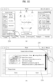
- FIGs. 12(a) and 12(b) are views illustrating one example of confirmation of information on stored items in a storage chamber through the display unit of the refrigerator in accordance with the embodiment of the present invention.
- FIGs. 12(a) and 12(b) illustrate a state in which storage information on 4 kinds of stored items in one storage chamber is input in advance. Further, it is assumed that only icons corresponding to 2 kinds of stored items which are lately stored (that is, information on which is input) in each storage chamber are displayed.
- an indicator 1220 indicating the number of stored items together with icons corresponding to information on the stored items are displayed in a specific storage chamber 1210.
- the indicator 1220 may be displayed only when the number of kinds of the stored items in the corresponding storage chamber exceeds 2, or be displayed at all times.
- the numeral displayed on the indicator 1220 may indicate the number of kinds of stored items, or indicate the number of input times. That is, when the same stored item is input twice, if the numeral displayed on the indicator 1220 indicates the number of kinds of stored items, the indicator 1220 displays 1, and when if the numeral displayed on the indicator 1220 indicates the number of input times, the indicator 1220 displays 2.
- a area corresponding to the storage chamber may be activated and magnified at a designated rate, as shown in FIG. 12(b) .
- the names of the stored items are displayed, and scroll buttons 1231 and 1233 to confirm other stored items are displayed at the left and right of the icons 1241 and 1243.
- FIG. 12(b) The case in that a bean curd icon 1243 is selected in FIG. 12(b) will be described with reference to FIGs. 13(a) and 13(b) .
- FIGs. 13(a) and 13(b) are views illustrating one example of confirmation of detailed information on a stored item in the storage chamber through the display unit of the refrigerator in accordance with the embodiment of the present invention.
- a popup window to confirm/change detailed information on bean curd is displayed, as shown in FIG. 13(a) .
- the shape of the popup window is basically similar to that of FIG. 8(d) . That is, an icon 1310 corresponding to a stored item, +/- buttons 1320 to adjust the number of the stored item, and a storage period change button 1330 may be displayed on the popup window 850. Further, a recommended dish view icon 1340, an icon 1350 to add the corresponding stored item to the shopping list, a wastebasket 1360 to delete storage information on the corresponding stored item, a confirmation icon 1360 and a cancellation icon 1370 may be displayed.
- the popup window of FIG. 13(a) differs from the popup window of FIG. 8(d) in that the popup window of FIG. 13(a) displays the detailed information as a value set when initial storage information is input.
- a popup window 1390 including recommended dishes using the corresponding stored item as a material may be displayed, as shown in FIG. 13(b) .
- FIGs. 14(a) to 14(d) are views illustrating one example of selection of a stored item through a voice command in the refrigerator in accordance with the embodiment of the present invention.
- the controller 280 activates the microphone 222, and when preparation to input a voice has been completed, a popup window 1420 to instruct a user to input a voice may be displayed, as shown in FIG. 14(b) .
- a popup window 1420 including an icon of a stored item according to a result of recognition may be displayed, as shown in FIG. 14(c) . If a stored item desired by a user through a voice command is garlic, the user selects an icon 1431 corresponding to garlic, and thus a window 1440 including an inner space graphic 1450 of the refrigerator may be displayed, as shown in FIG.
- FIGs. 15(a) and 15(b) are views illustrating one example of selection of a stored item through a virtual keyboard in the refrigerator in accordance with the embodiment of the present invention.
- a virtual keyboard 1530 may be displayed, as shown in FIG. 15(b) .
- Text input through the virtual keyboard 1530 may be displayed in an upper area 1520, and when input of a desired search word has been completed, a user may select a search button 1540.
- FIGs. 16(a) to 16(d) are views illustrating one example of registration and storage of a new stored item through the virtual keyboard in the refrigerator in accordance with the embodiment of the present invention.
- FIGs. 16(a) to 16(d) it is assumed that information regarding to an item "potato snack" is not stored in the memory 250 and an icon according to frequency and an icon according to category corresponding thereto are not present.
- a user inputs a word "potato snack” through the virtual keyboard and executes search, as shown in FIG. 16(a) .
- a menu 1610 to add a kind of stored item called “potato snack” is displayed, as shown in FIG. 16(b) .
- a popup window 1620 to confirm whether or not the corresponding stored item is added to a user database may be displayed, as shown in FIG. 16(c) . If "yes” to add the corresponding stored item is selected within the popup window 1620, a window including the inner space graphic of the refrigerator may be displayed, as shown in FIG. 16(d) .
- a subsequent process including setting of detailed information after a storage position has been selected is the same as the above-described process.
- Storage information on the above-described stored item may be transmitted to an external device, or information stored in the external device may be called to the refrigerator.
- the external device may be a mobile terminal, such as a smart phone, or a server. Connection with the external device may be executed through the wireless communication unit 210. For this purpose, a method of inputting a command will be described with reference to FIGs. 17(a) to 17(d) .
- FIGs. 17(a) to 17(d) are views illustrating one example of execution of input of a command to communicate with an external device in the display unit of the refrigerator in accordance with the embodiment of the present invention.
- a user may select a sending button 1710 at the lower end of the food management menu, as shown in FIG. 17(a) . Thereby, a popup window indicating a sending state may be displayed, as shown in FIG. 17(b) .
- a calling button 1720 at the lower end of the food management menu, as shown in FIG. 17(c) . Thereby, a popup window indicating a calling state may be displayed, as shown in FIG. 17(d) .
- an icon displayed on a storage chamber in the refrigerator inner space graphic may be added to the recipe or the shopping list. This will be described with reference to FIGs. 18(a) to 18(d) .
- FIGs. 18(a) to 18(d) are views illustrating one example of addition of a stored item displayed on the display unit to another menu in the refrigerator in accordance with the embodiment of the present invention.
- a user may select a storage chamber 1810, in which a stored item to be added to the recipe is stored, to activate the corresponding storage chamber 1810, and drag an icon 1820 of the stored item to be added to a recipe menu 1830 provided at the lower end, as shown in FIG. 18(a) .
- a popup window notifying a result of addition may be displayed, as shown in FIG. 18(b) .
- the user may select the storage chamber 1810, in which a stored item to be added to the shopping list is stored, to activate the corresponding storage chamber 1810, and drag an icon 1820 of the stored item to be added to a shopping list menu 1840 provided at the lower end, as shown in FIG. 18(c) .
- a popup window notifying a result of addition may be displayed, as shown in FIG. 18(d) .
- An icon displayed on a storage chamber on the refrigerator inner space graphic may be deleted. This will be described with reference to FIGs. 19(a) to 19(d) .
- FIGs. 19(a) to 19(d) are views illustrating one example of deletion of a stored item displayed on the display unit of the refrigerator in accordance with the embodiment of the present invention.
- a stored item may be deleted by activating a storage chamber in which the stored item is stored and then dragging an icon 1910 of the stored item desired to be deleted to a wastebasket 1920, as shown in FIG. 19(a) .
- deletion of the stored item means not only deletion of the icon displayed on the storage chamber, but also deletion of storage information on the stored item corresponding to the deleted icon.
- a popup window 1930 notifying throwing of the corresponding stored item into the wastebasket 1920 may be displayed, as shown in FIG. 19(b) .
- deletion of a designated range is possible.
- a menu button 1940 provided at the upper end is selected, as shown in FIG. 19(c)
- a menu 1950 to select a deletion range may be displayed at the lower end, as shown in FIG. 19(d) . That is, deletion of a designated range, such as deletion of the entirety of the freezing chamber, deletion of the entirety of the refrigerating chamber, deletion of the entirety of the magic space or deletion of the entirety of the refrigerator, may be specified, and when the range is specified, information on stored items stored in the corresponding range may be deleted at a time.
- FIG. 20 is a view illustrating one example of an initial picture of a recipe menu displayed on the display unit of the refrigerator in accordance with the embodiment of the present invention.
- the recipe menu has a function of searching or being recommended information on dishes made using a stored item in a storage chamber or dishes according to category, and may be called by selecting the recipe icon 642 of the lower portion 640 of the initial picture of FIG. 6 .
- a stored item selection area 2010 is prepared at the right.
- the stored item selection area 2010 may change an icon arrangement sequence or an alignment reference of stored items according to selection of a storage period tab 2011 displaying icons aligned in the order that the storage period expiration dates of the stored items are near and a possessed food tab 2013 displaying possessed stored items in order of category or in alphabetical order.
- a material area 2020 in which a stored item selected as a material of a dish is arranged is prepared at the upper end of the center.
- a recipe view button 2030 provided at the lower end, a recipe list using the stored item corresponding to an icon 2021 located in the material area 2020 as a material may be displayed in a recipe result area 2040.
- the icon 2021 of the stored item located in the material area 2002 may be added from the food management menu, as shown in FIG. 18(a) , or be selected from the right stored item selection area 2010.
- a method of adding a stored item icon from the stored item selection area 2010 to the material area 2020 will be described with reference to FIGs. 21(a) to 21(d) .
- FIGs. 21(a) to 21(d) are views illustrating a method of adding a stored item icon as a recipe material in the recipe menu displayed on the display unit of the refrigerator in accordance with the embodiment of the present invention.
- the corresponding icon 2110 when a user maintains touch with a chicken icon 2110 for a designated time (for example, 1 second) under the condition that the storage period tab is selected, the corresponding icon 2110 is activated to a movable state. Then, when the user drags ad drops the corresponding icon 2110 to the material area 2120, the chicken icon 2110 may be arranged in the material area 2120.
- a designated time for example, 1 second
- the user may select the possessed food tab 2130, activate an icon 2140 corresponding to young radish kimchi from among displayed icons and then drag the icon 2140 to the material area, as shown in FIG. 21(c) . Thereafter, when a recipe view button 2150 is selected, as shown in FIG. 21(d) , recipes using chicken and young radish kimchi as materials may be displayed in a recipe result area 2160 provided at the left.
- FIGs. 22(a) and 22(b) are views illustrating display of detailed information on a recipe displayed on the display unit of the refrigerator in accordance with the embodiment of the present invention.
- a popup window 2220 including detailed information on the selected recipe may be displayed, as shown in FIG. 22(b) . If the detailed information on the recipe is not displayed at a time on the popup window 2220, a scroll bar 2230 which is scrollable in the vertical direction through touch and drag input and indicates the position of the currently displayed portion with respect to the entire contents may be additionally displayed. Further, although not shown in the drawings, materials which are required by the selected recipe but are not present in the stored item information may be automatically added to the shopping list.
- An icon displayed on the stored item selection area may be moves to another menu, or be deleted. This will be described with reference to FIGs. 23(a) and 23(b) .
- FIGs. 23(a) and 23(b) are views illustrating one example of a method of moving or deleting a stored item icon displayed on the display unit of the refrigerator in accordance with the embodiment of the present invention.
- a user may activate an icon 2310 displayed on the stored item selection area displayed at the right of the recipe menu, and then drag the icon 2310 to a shopping list button 2320 or a wastebasket 2330, as shown in FIG. 23(a) . If the icon 2310 is dragged to the shopping list button 2320, a stored item corresponding to the corresponding icon 2310 may be added to the shopping list which will be described later, and if the icon 2310 is dragged to the wastebasket 2330, information on the corresponding stored item may be deleted.
- the icon 2340 may be deleted from the material area by applying touch to the corresponding icon 2340.
- the corresponding icon 2340 is deleted from the material area, but information on a stored item corresponding to the icon 2340 may be maintained.
- a user may search recipes regardless of icons added to the material area. This will be described with reference to FIGs. 24(a) to 24(d) .
- FIGs. 24(a) to 24(d) are views illustrating one example of a method of searching for recipes in the display unit of the refrigerator in accordance with the embodiment of the present invention.
- a dish icon 2410 according to theme, a dish icon 2420 according to material and an oven dish icon 2430 are arranged at the lower end of the recipe menu.
- a popup window in which a theme selection area 2440 is arranged at the upper end and a sub-theme list 2450 belonging to a selected theme is arranged under the theme selection area 2440 may be displayed, as shown in FIG. 24(b) .
- a popup window in which a material selection area 2460 is arranged at the upper end and a sub-concept list 2470 of a selected material is arranged under the material selection area 2460 may be displayed, as shown in FIG.
- a popup window in which a cooking mode selection area is arranged at the upper end and a sub-cooking mode list of a selected mode is arranged under the cooking mode selection area may be displayed, as shown in FIG. 24(d) .
- FIGs. 25(a) to 25(c) Next, a method of confirming detailed information on a searched recipe will be described to FIGs. 25(a) to 25(c) .
- FIGs. 25(a) to (c) are views illustrating one example of a method of confirming detailed information on a searched recipe in the display unit of the refrigerator in accordance with the embodiment of the present invention.
- FIG. 25(a) illustrates a subsequent process of FIG. 24(b) .
- the popup window in which the theme selection area is arranged at the upper end and the sub-theme list belonging to a selected theme is arranged under the theme selection area is displayed, as described above.
- a list of recipes belonging to the daily dish 2519 is displayed, as shown in FIG. 25(b) .
- a popup window 2530 including detailed information on a boiled bean curd recipe may be displayed, as shown in FIG. 25(c) .
- a scroll bar 2540 which is scrollable in the vertical direction through touch and drag input and indicates the position of the currently displayed portion with respect to the entire contents may be additionally displayed.
- FIGs. 26(a) and 26(b) are views illustrating one example of a method of calling the food management menu when the recipe menu is displayed on the display unit of the refrigerator in accordance with the embodiment of the present invention.
- the initial picture of the food management menu may be displayed, as shown in FIG. 26(b) .
- FIGs. 27(a) to 27(c) are views illustrating one example of an initial picture of the shopping list menu displayed on the display unit of the refrigerator in accordance with the embodiment of the present invention.
- the shopping list menu has a function of confirming/amending/deleting information on stored items added to the shopping list in the food management menu or the recipe menu.
- the shopping list menu may be called by selecting the shopping list icon 643 at the lower portion 640 of the initial picture of FIG. 6 .
- the touch screen 241 switches from the initial picture of FIG. 6 to the shopping list menu picture, as shown in FIG. 27(a) .
- icons 2710 of stored items saved as the shopping list and check boxes 2720 provided at the right sides of the respective icons 2710 may be displayed at the center of the initial picture of the shopping list menu.
- a sending button 2730 to send the shopping list to an external device and a calling button 2740 to obtain the shopping list from an external device are arranged at the lower end. Further, when an all selection/release button 2750 provided at the lower end is selected, as shown in FIG. 27(b) , all stored items included in the shopping list are selected, and thus all check boxes 2720 located at the right sides of the respective icons 2710 are checked.
- the checked states of the all check boxes may be released. Further, if a user desires to delete all or some of the stored items included in the shopping list, the check boxes of stored items desired to delete are selected and then a wastebasket button 2760 provided at the lower end is selected, thereby being capable of deleting the selected stored items.
- a widget is a mini application program made to directly use functions, such as weather, calendar, a calculator, etc., not through a Web browser.
- the widgets in accordance with the present invention may be displayed at the center of the initial picture, and it is assumed that the widgets are divisionally arranged at three pictures which are scrollable to right and left.
- FIGs. 28(a) to 28(c) are views illustrating one example of a widget configuration displayed on the display unit of the refrigerator in accordance with the embodiment of the present invention.
- FIG. 28(a) illustrates widgets at the left position from among the widgets arranged on three pictures.
- a page indicator 2810 indicating a picture on which the currently displayed widgets are arranged, from among the three pictures.
- the page indicator 2810 includes points prepared in number corresponding to the number of the respective pictures, and exhibits visual effects to discriminate a point corresponding to the currently displayed picture from other points.
- a memo widget 2820 to display a memo written through a memo function which will be described later and a weather widget 2830 to indicate weather of a predetermined region may be displayed on the left picture.
- the page indicator 2810 provides visual effects to the central point to indicate display of the central picture, as shown in FIG. 28(b) .
- a calendar widget 2840 to display a schedule according to designated unit (for example, 1 month) is displayed at the left of the central picture, and a storage period notification widget 2850 to display an icon of a stored item, storage period expiration of which is near, may be displayed at the right of the central picture.
- the page indicator 2810 provides visual effects to the right point to indicate display of the right picture, as shown in FIG. 28(c) .
- a recommended recipe widget 2860 randomly displaying recipes using stored items as materials is displayed at the left of the right picture, and a refrigerator management widget 2870 indicating an operating state of the refrigerator is displayed at the right of the right picture.
- the user may input a flicking touch in the rightward direction.
- FIGs. 29(a) to 29(d) are views illustrating one example of setting a region of the weather widget displayed on the display unit of the refrigerator in accordance with the embodiment of the present invention.
- a popup window 2920 for region setting may be displayed, as shown in FIG. 29(b) .
- a region list is not displayed at a time on the popup window 2920, the region list may be scrolled in the vertical direction through drag/flicking input.
- a popup window 2940 including a subregion list is displayed, as shown in FIG. 29(c) .
- a popup window 2950 indicating receiving weather of the corresponding region from an external server may be displayed after setting of the region has been completed, as shown in FIG. 29(d) .
- the weather widget displays weather of the changed region.
- FIG. 30 is a view illustrating one example of use of the storage period notification widget displayed on the display unit of the refrigerator in accordance with the embodiment of the present invention.
- an icon 3010 of a stored item, storage period expiration of which is near is displayed, as shown in FIG. 30 .
- the displayed icon 3010 may be dragged to a recipe menu 3020 provided at the lower end, thus being capable of being added to the material area of the recipe menu. Further, if the displayed icon 3010 is dragged to a shopping list menu 3030 provided at the lower end, the icon 3010 may be added to the shopping list menu.
- the 6 refrigerator management menus include menus regarding a freezing chamber temperature setting button 3111, a refrigerating chamber temperature setting button 3112, a special freezing setting button 3113 increasing the freezing velocity of the freezing chamber, a special freezing chamber operation setting button 3114, a filter device setting button 3115 and a smart power saving operation button 3116.
- Each of the freezing chamber and refrigerating chamber temperature setting buttons 3111 and 3112 includes a touch button to lower and raise temperature, and a window showing the current temperature of the freezing chamber or the refrigerating chamber.
- Each of the special freezing setting button 3113, the special freezing chamber operation setting button 3114 and the smart power saving operation button 3115 includes a touch button to select 'operating' and 'off', and the filter device setting button 3115 includes an 'auto' button automatically operable, a 'power' button to improve sterilizing performance during operation, and a 'off' button.
- a virtual refrigerator in which a refrigerating chamber and a freezing chamber are completely opened is displayed on the initial picture of refrigerator management, and the positions of a special freezing chamber and a filter device provided in the freezing chamber and the refrigerating chamber are displayed on the virtual refrigerator.
- Buttons regarding the above-described 6 menus are arranged around the virtual refrigerator, and a user may touch these buttons to operate the refrigerator.
- buttons are touch buttons
- these touch buttons may be capacitive switches which are operated through reaction with a human body close to the buttons by a designated distance or an object having static electricity without mechanical operation.
- the user in order to adjust the temperature of the freezing chamber or the refrigerating chamber, the user operates the freezing chamber temperature setting button 3111 or the refrigerating chamber temperature setting button 3112.
- the freezing chamber and the refrigerating chamber temperature setting buttons 3111 and 3112 include an up button and a down button so as to raise and lower the temperatures of the freezing chamber and the refrigerating chamber.
- buttons 3111a or a refrigerating chamber temperature state window 3112a are changed.
- Temperature adjustment of the freezing chamber or the refrigerating chamber is executed according to opening and closing operation of a cold air damper, change of an operation factor of the compressor, on/off of the cold air fan, or change of a rotating velocity of the cold air fan.
- the freezing chamber in the special freezing operation mode more rapidly reaches a target temperature than in the general freezing operation mode, and the special freezing operation may be executed while increasing the rotating velocity of the cold air fan.
- the window of the freezing chamber F of the virtual refrigerator may be automatically turned off.
- the special freezing chamber SF means a special freezing chamber which has a lower temperature than the freezing chamber and a relatively high freezing velocity in order to store food, such as meat, in the optimal state.
- Special freezing shown in FIG. 33 means rapid freezing of the entirety of the freezing chamber, and is used when a large amount of items are put into the freezing chamber.
- the compressor and the cold air fan are operated for a longer time than in the general freezing operation.
- the special freezing chamber shown in FIG. 34 means a storage space separately provided in the freezing chamber, and special freezing chamber operation means concentration of cold air into the storage space.
- the special freezing chamber operation is executed.
- FIGs. 35A to 35C are views illustrating display states regarding operation of the filter device 295 (with reference to FIG. 1 ).
- FIGs. 35A to 35C state the filter device 295 as a sterilization filter, the scope or function of the filter device 295 is not limited to the sterilization filter.
- the filter device 295 in accordance with the present invention may execute a sterilization function of removing virus or bacteria from the inside of the refrigerator and a deodorization function of removing odors from the inside of the refrigerator.
- the filter device 295 provided in the refrigerating chamber 6 (with reference to FIG. 1 ) of the main body of the refrigerator is operated to filter air within the refrigerating chamber 6.
- the lighting device 296 (with reference to FIG. 1 ) is provided around the filter device 295 of the refrigerating chamber 6. When the 'auto' button or the 'power' button is touched, the lighting device 296 is turned on while operating the filter device 295.
- operation of the filter device 295 when the 'auto' button is touched and operation of the filter device 295 when the 'power' button is touched are basically the same.
- operation of the filter device 295 when the 'auto' button is touched and operation of the filter device 295 when the 'power' button is touched are different in that a rotating velocity and an operating time of a fan unit 295b (with reference to FIG. 1 ) constituting the filter device 295 when the 'power' button is touched are increased.
- a replacement button 3601 in the refrigerating chamber R of the virtual refrigerator of the display unit 241 is popped up.
- a user or an AS mechanic may replace the filter unit 295a with a new one on seeing the popup state of the replacement button 3601.
- the replacement button 3601 When the replacement button 3601 is pressed for a designated time (for example, 5 seconds), the replacement button 3601 may disappear.
- FIGs. 37 to 40 are views illustrating a power saving command to reduce power consumed during operation of the refrigerator.
- a power saving mode selection popup window 3701 to select one of power saving modes is displayed.
- the power saving modes displayed on the popup window 3701 of FIG. 37 include a midnight power saving mode, a user power saving mode and an auto power saving mode.
- a midnight power saving function is executed.
- the midnight power saving function means minimization of operation of the refrigerator in a predetermined midnight time section (for example, 0 o'clock ⁇ 4 o'clock) to minimize a power consumption rate.
- the number of usage frequency of the refrigerator is remarkably reduced in the midnight time section due to user's sleeping.
- the operation factor of the compressor, operation of the cold air fan or operation of the defrost heater in the midnight time section are reduced as compared to in the general operation mode, thereby reducing power consumption.
- the temperature in the storage chamber is raised and such raise of the temperature acts as load.
- the compressor is operated, or the cold air fan is operated to supply cold air.
- the compressor or the cold air fan is not immediately operated as long as the temperature does not exceed the upper limit of a set inner temperature range of the refrigerating chamber 5 (with reference to FIG. 1 ) or the freezing chamber 6 (with reference to FIG. 1 ( )).
- the compressor or the cold air fan Only when the temperature of the refrigerating chamber or the freezing chamber reaches the upper limit of the set inner temperature range of the refrigerating chamber or the freezing chamber, the compressor or the cold air fan is operated.
- a message 3810 'midnight power saving' is displayed on the initial picture 3101 of the refrigerator management menu, thereby notifying the user of midnight power saving operation.
- FIGs. 39A and 39B illustrate selection of the user power saving mode so as to execute power saving operation in a time section selected by a user.
- a time setting window 3910 to set time is displayed.
- the user may set one time section or plural time sections as power saving time.
- the set time section may be a time section when the user does not frequently use the refrigerator, for example, leave-time or a time section between the office-going hour and the home-returning hour.
- a message 3920 'user power saving' is displayed on the initial picture of the refrigerator management menu.
- power saving operation is executed so as to cause the minimum power consumption within the set temperature range of the storage chamber, by lowering of the operation factor of the compressor or lowering of the operation performance of the cold air fan in the time section set by the user.
- FIG. 40 illustrates selection of the auto power saving mode on the power saving mode selection window.
- an auto power saving option 4001 when the user selects an auto power saving option 4001, a brief description of auto power saving and a power condition and charge information notification button 4002 are displayed.
- the auto power saving function means power saving operation of the refrigerator based on information regarding a time zone having the highest electric charges which is recognized by a server communicable with the refrigerator and is transmitted to the refrigerator.
- the auto power saving function is prepared to apply the trend of electric charges toward change from a fixed charge system unrelated to season and time to a variable charge system variable according to season and time to the refrigerator.
- an auto power saving notification message 4010 is displayed on the main setting window of the refrigerator management menu, as shown in FIG. 40 .
- FIG. 41 is a view illustrating display of a schedule when the schedule button 646 (with reference to FIG. 6 ) of the main menu displayed on the display unit is touched.
- a basic schedule picture 4101 is displayed in unit of month like a calendar, and when the picture 4101 is scrolled in the vertical direction under the condition that the picture 4101 is touched, the current month may move to the previous month or the next month.
- the date corresponding to today (February 27, 2011) is shown in a loud color so as to be discriminated from other dates.
- a schedule input window 4210 in which time zones of the corresponding date D are sequentially displayed is popped up.
- the schedule input window 4210 moves vertically and shows other time zones (Sequence (2)) .
- the user inputs a name and contents of the schedule on the detailed schedule information input window 4301 (Sequence 1).
- a keyboard input window allowing the user to input the name and contents of the schedule through the keyboard may be displayed.
- the user moves the corresponding compartment downward under the condition that the user maintains touch with the compartment.
- an input window to input the place is displayed, and when the user touches the input window, the keyboard input window is displayed.
- the user inputs the place using the keyboard input window (Sequence 4).
- setting once, setting every day, setting weekdays (Mon-Fri), setting every week (the corresponding day of the week), setting every month (the first week), setting every month (the corresponding day), and setting every year (the corresponding day) may be carried out. This may be carried out by touching a window under a portion displaying 'repetition' (Sequence 6).
- FIGs. 44A and 44B are views illustrating a process of amending or deleting the schedule input in advance on the display unit 241.
- FIG. 44A a figure 4401 for an index is displayed at a date having an input schedule on the basic schedule picture 4101.
- the schedule input window 4210 in which the schedule is recorded is displayed, as shown in FIG. 44A .
- a schedule confirmation button 4410 displayed at the upper end of the schedule input window 4210 in the above state As shown in FIG. 44B , a schedule amendment button 4411 and a schedule deletion button 4412 are displayed at the lower end of the schedule input window 4210.
- the schedule amendment button 4411 When the user touches the schedule amendment button 4411, the detailed schedule information input window 4301 shown in FIG. 43 is popped up, and the schedule may be amended through the detailed schedule information input window 4301 (Sequence 1).
- the schedule deletion button 4412 when the user touches the schedule deletion button 4412, the corresponding schedule may be deleted.
- FIG. 45 and FIGs. 46A to 46C are views illustrating rapid schedule registration through the display unit 241.
- a schedule confirmation button 4410 on the basic schedule picture 4101 when a user touches the schedule confirmation button 4410 on the basic schedule picture 4101, a schedule list button 4501, a daily search button 4502, a weekly search button 4503, a new schedule input button 4504, a today schedule search button 4505 and an environment setting button 4506 are popped up at the lower end of the basic schedule picture 4101.
- a daily schedule input window 4210 is displayed, as shown in FIG. 46B , and daily schedule may be searched.
- schedule in time zones of a specific date may be searched, and when the user moves the daily schedule input window 4210 right and left under the condition that the user maintains touch with the daily schedule input window 4210, a date is changed to another date, and schedule in time zones of the changed date may be searched.
- a weekly schedule list 4610 is displayed, as shown in FIG. 46C .
- schedule in time zones of the respective seven dates belonging to a specific week may be searched, and when the user moves the weekly schedule list 4610 right and left under the condition that the user maintains touch with the weekly schedule list 4610, a week is changed to another week, and schedule in time zones of the dates of the changed week may be searched.
- FIGs. 47 to 52B are views illustrating processing a user's memo through the display unit 241.
- FIG. 48A when the user touches a memo input window 4801 on the initial memo picture 4701, the initial memo picture 4701 is switched to a text input keyboard picture 4810.
- a memo storage button 4820 at the side of the memo input window 4801
- the memo is stored and a memo storage confirmation window 4830 is displayed.
- FIGs. 49A and 49B are views illustrating input of a picture or a memo in user's own handwriting other than input of a memo through the text keyboard 4811.
- the user may draw a memo by touching the drawing memo picture 4910.
- the user may draws a memo within a frame 4911 shown by a dotted line (a) , may touch a line width setting button 4912 to set a line width (b), and may press an eraser button 4913 to erase the drawn memo ( ⁇ ).
- the user may touch a color selection button 4914 to determine a line color (d), and may touch an initialization button 4915 to delete all of drawn memos (e) when the user desires to erase all of the drawn memos at a time.
- the user may touch a storage button 4916 to store the drawn memo (f), and touches a cancellation button 4917 to cancel the drawing memo (g).
- the user may touch the storage button 4916 to store the drawn memo.
- FIG. 50 is a view illustrating a process of erasing a drawn memo.
- the user may erase the drawn memo by touching the eraser button 4913 and touching a portion P desired to be erased up, down, right and left, i.e., in all directions.
- FIGs. 51A and 51B are views illustrating a process of deleting an unnecessary memo.
- a stored memo is displayed in a virtual Post-it shaped memo display window 5101 on the initial memo picture 4701.
- a popup window 5110 to reconfirm whether or not the memo is deleted is popped up.
- a popup window 5120 to confirm deletion of the memo is popped up, as shown in FIG. 51B , and thereby the process of deleting the unnecessary memo has been completed.
- FIGs. 52A and 52B are views illustrate storage of a memo in a background picture of the display unit 241, and therethrough, the stored memo may be displayed on the widget of the background picture.
- a user selects the specific memo display window 5101 displayed on the initial memo picture 4701 (Sequence 1), and touches a background picture storage button 5110 provided at the lower end of the initial memo picture 4701 (Sequence 2).
- an indicator indicating 'Home' is displayed at the upper end of the selected memo, and a color of the selected memo is discriminated from colors of other regions.
- FIG. 53A is a view illustrating a main environment setting picture to set the environment of the display unit 241.
- the environment setting button of the main menu shown in FIG. 6 the main environment setting picture is displayed on the display unit 241.
- total 8 sub-menus are displayed on the main environment setting picture 5301.
- the 8 sub-menus include menus regarding a screen brightness setting button 5311, a volume setting button 5312, a wireless network setting button 5313, an update button 5314, a screen setting button 5315, a date/time setting button 5316, a smart diagnosis button 5317 and a user registration/initialization setting button 5318.
- a screen brightness setting popup window 5320 is displayed, as shown in FIG. 53B .
- a scroll bar 5321 to adjust screen brightness is displayed on the screen brightness setting popup window 5320, and when the user moves the scroll bar 5322 to right and left to set desired brightness and then touches a confirmation button 5322, setting of screen brightness is completed.
- FIG. 54 is a view illustrating a process of setting volume.
- volume setting popup window 5410 to set volume is popped up, as shown in FIG. 54 , and a scroll bar 5411 to adjust the intensity of volume is displayed on the volume setting popup window 5410.
- FIG. 55A illustrates a wireless network setting picture 5420.
- the wireless network setting picture 5420 is displayed on the display unit 241.
- this embodiment illustrates use of a Wi-Fi system as a wireless network
- the present invention is not limited thereto.
- the user may touch a Wi-Fi on box button 5421, as shown in FIG. 55B .
- FIGs. 55B and 55C and FIG. 56 are views illustrating a detailed process of connecting the wireless network.
- a wireless password popup window for connection with the wireless network is popped up, as shown in FIG. 55C (here, U+ Net97A3 is an ID number of a wireless sharer).
- the user inputs a password on the wireless password popup window (in the case of setting of a password of the wireless sharer) (Sequence 2).
- connection of the wireless network is completed, as shown in FIG. 56 .
- FIG. 57 is a view illustrating a wireless password keyboard, and the wireless password keyboard may be converted among Korean/alphabet/numeral.
- Various types of passwords may be set using conversion keys and special function keys shown in FIG. 57 .
- FIGs. 58A and 58B are views illustrating a process of confirming user registration to update information, such as firmware or recipes.
- a user registration and initialization popup window 5810 is displayed, if the user not been registered.
- the user may execute user registration by inputting an ID and a password which were given to the user when the user purchases the refrigerator, or an ID and a password which were input through a homepage of a manufacturer on the user registration and initialization popup window 5810, and touching a new registration button 5812.
- FIG. 58B a picture shown in FIG. 58B is displayed, and the user ID and password are displayed on the picture.
- the user touches a user change button 5821 to execute user change, and when initialization of user information is required, the user touches a user information initialization button 5822.
- FIG. 59A is a view illustrating update of firmware or recipes on the display unit.
- a version confirmation popup window 5920 to confirm whether or not current software is the latest version, as shown in FIG. 59B .
- an update confirmation popup window 5930 is displayed, as shown in FIG. 59B , and the current versions of the firmware and the recipes and whether or not there are factors of the firmware and the recipes to be updated are displayed on the update confirmation popup window 5930.
- the user may update the firmware by inserting the SD memory card in which updated firmware is stored into the insertion slot 245 (with reference to FIG. 4 ) and then touching an SD card button 5932.
- rebooting is automatically executed.
- an update progress popup window 6120 is displayed, as shown in FIG. 61 , and when update has been completed, the display unit is returned to the initial environment setting picture 5301, as shown in FIG. 53A .
- a power saving screen or a lighting time may be selected through screen setting.
- a user touches the screen setting button 5315 on the initial environment setting picture 5301, as shown in FIG. 62 .
- a screen setting popup window 6220 is displayed.
- the user may select a power saving screen option, a lighting time option and an auto on option on the screen setting popup window 6220.
- the power saving screen means a state of the screen displayed by the display unit so as to save power after a designated lighting time from use of the display unit by the user.
- the user may select one of OFF of the screen, lowering of the intensity of illumination of the screen, and display of time.
- the user may select auto ON, as shown in a portion 6221 shown by a dotted line on the screen setting popup window 6220.
- Auto ON means the case in which the display unit is automatically brightened when the user touches and the case in which the display unit is automatically brightened when the user touches or the door or the sub-storage chamber of the refrigerator (expressed as the magic space in this embodiment).
- the screen setting popup window 5220 when the user selects screen OFF or screen darkening, the screen is turned off or darkened after a designated lighting time, and if the screen is retouched, the screen is in a locked state and thus a corresponding touch command is not executed even though the user touches the screen.
- the user touches the date/time button 5316 on the initial environment setting picture 5301, as shown in FIG. 65 .
- the initial environment setting picture 5301 is switched to a date/time setting picture, and date and time are displayed on the corresponding picture.
- date and time information is received through the wireless network and is applied to the display unit.
- the user touches a date setting compartment 6522 or a time setting compartment 6523.
- a date setting popup window 6610 or a time setting popup window 6620 is displayed, as shown in FIG. 66 , and date or time may be set using buttons provided on these popup windows 6610 and 6620.
- FIG. 67 is a view illustrating a process of executing smart diagnosis on the initial environment setting picture.
- Smart diagnosis is a diagnosis method which transmits a specific sound generated from the refrigerator as an audio signal to an A/S center and judges whether or not the refrigerator is out of order using such an audio signal.
- a smart diagnosis guidance picture 6720 is displayed, and particulars followed by the user and a diagnosis start button 6721 are displayed on the smart diagnosis guidance picture 6720.
- a method using smart diagnosis starts from opening of the door of the refrigerator and putting a cellular phone C on the hole of the speaker 242 located at the upper end of the main body of the refrigerator, as shown in FIG. 68 .
- the user touches the diagnosis start button 6721.
- an audio signal may be generated from the hole of the speaker 242, and remaining time taken to execute diagnosis may be displayed on the smart diagnosis guidance picture 6720.
- the user After audio signal transmission has been completed, the user receives an answer regarding a result of smart diagnosis from a consultant and takes measures, thereby judging whether or not the refrigerator is out of order and taking measures to cope with such a situation.
- FIG. 69 is a view illustrating a process of registering a user through the initial environment setting picture 5301.
- a user registration and initialization popup window 6920 is displayed, and an ID input window 6921 and a password input window 6922 are displayed on such a popup window 6920.
- the user inputs an ID and a password registered on a Website operated by a refrigerator manufacturer into the ID input window 6921 and the password input window 6922.
- the user interface displayed through the above-described display unit of the refrigerator may be implemented through a touch screen of a wireless terminal.
- the above-described user interface may be implemented by an exclusive remote controller provided with a touch screen or a smart phone provided with an application to control the refrigerator.
- the smart phone may include a wireless communication unit to exchange information with the outside wirelessly, a touch screen to recognize touch input of a user, and a memory to store input and output information.
- the smart phone may include other elements in addition to the above elements.
- the smart phone is referred to as a "wireless terminal", for convenience.
- FIG. 71 is a view illustrating one example of display of an application to control the refrigerator in accordance with the embodiment of the present invention on a wireless terminal.
- an icon 7110 executing a shortcut function of the corresponding application may be displayed on a background picture (home screen) or a main menu, as shown in FIG. 71(a) .
- An ID/password for log-in may be equal to or different from an ID/password set in the refrigerator.
- an initial picture of the application is displayed, as shown in FIG. 71(c) . If the wireless terminal is connected to the refrigerator through a server or is directly connected to the refrigerator and thus information (a shopping list, information of stored items, or etc.) of the wireless terminal is updated, i.e., synchronized with the refrigerator, a notification window 7120 notifying this fact may be displayed.
- the initial picture displayed after log-in is the food management menu
- a configuration of the food management menu will be described with reference to FIG. 72 .
- FIG. 72 is a view illustrating one example of display of the food management menu of the application to control the refrigerator on the wireless terminal in accordance with one embodiment of the present invention.
- menu buttons or icons when the food management menu is displayed on the wireless terminal is considerably similar to the user interface of the refrigerator described with reference to FIG. 7(b) .
- some menu buttons or icons may be omitted or changed to other shapes due to problems caused by the size of the touch screen of the wireless terminal.
- a sending button 7210 to send information on stored items to the refrigerator or the external server, and a calling button 7220 to call information on stored items from the refrigerator or the external server are arranged at the upper end of the food management menu.
- An input button according to frequency and a category input button 7230 to specify stored items are arranged below the sending button 7210 and the calling button 7220.
- a graphic 7240 representing the inner shape of the refrigerator is displayed at the center of the food management menu, and an indicator 7250 indicating kinds or the number of stored items stored in a corresponding storage chamber if there is storage information on items stored in advance is displayed on respective storage chambers in the graphic 7240.
- a button 7260 to call a virtual keypad is arranged under the graphic 7240, and a menu button area 7270 to call respective menus, such as the food management menu, the recipe menu, the shopping list menu, and the refrigerator temperature menu, is arranged at the lower end of the food management menu.
- FIGs. 73(a) and 73 (b) are views illustrating one example of a method of confirming information on stored items in the storage chamber through the food management menu of the application to control the refrigerator on the wireless terminal in accordance with the embodiment of the present invention.
- a list of icons of the stored items may be displayed, as shown in FIG. 73(b) .
- a button 7320 to add the corresponding stored item as a recipe material and a button 7330 to delete the corresponding icon are arranged at the side of each of the icons.
- FIGs. 74(a) and 74(b) are views illustrating one example of a method of confirming detailed information on a stored item in the storage chamber through the food management menu of the application to control the refrigerator on the wireless terminal in accordance with the embodiment of the present invention.
- FIG. 74(a) illustrates the subsequent process of FIG. 73(b) .
- a stored item detailed information picture may be displayed, as shown in FIG. 74(b) .
- a recommended recipe button 7420 to output recipes using the corresponding stored item as a material is arranged on the stored item detailed information picture.
- a storage period change button 7450 to change the storage period of the corresponding stored item and +/- buttons 7460 to adjust the number of the corresponding stored item may be displayed below the above-described buttons.
- Detailed functions of the respective buttons are similar to those of the user interface, and a detailed description thereof will thus be omitted.
- FIGs. 75(a) and 75 (b) are views illustrating one example of a method of specifying a stored item to be added through the food management menu of the application to control the refrigerator on the wireless terminal in accordance with the embodiment of the present invention.
- the icons of the stored items aligned in order of decreasing input frequency may be displayed, as shown in FIG. 75(a) .
- icons corresponding to categories of the stored items may be displayed, as shown in FIG. 75(b) .
- category classification may be equal to category classification described in the user interface of the refrigerator.
- FIG. 76 is a view illustrating one example of a recipe menu configuration of the application to control the refrigerator on the wireless terminal in accordance with the embodiment of the present invention.
- the recipe menu may be called by selecting a recipe button 7610 from a menu button area provided at the lower end.
- a sending button 7620 to send recipe information to the refrigerator or an external server and a calling button 7630 to call recipe information from the refrigerator or the external server are arranged at the upper end of the recipe menu.
- a cooking container icon 7640 to store a material which is a target object, the recipes of which are searched, is displayed below the sending button 7620 and the calling button 7630. If the cooking container icon 7640 is selected, a picture corresponding to the material area 2020 described with reference to FIG. 20 may be displayed entirely or a through a popup window.
- a recipe view button 7650 to search for and output recipes using stored items added to the cooking container icon 7640 as materials is displayed below the cooking container icon 7640.
- Buttons 7660 to specify the stored items to be added to the cooking container icon 7640 are arranged below the recipe view button 7650.
- a storage period button to confirm stored items, the storage period expiration dates of which are near and a possessed food button to confirm stored item information are respectively displayed.
- a button area 7670 to search for a recipe regardless of the stored items added to the cooking container icon 7640 is arranged at the lower end of the recipe menu.
- FIGs. 77(a) to 77(d) are views illustrating one example of a method of searching for a recipe by the application to control the refrigerator executed on the wireless terminal in accordance with the embodiment of the present invention.
- FIG. 77(a) may be displayed if a dish button according to theme is selected from the button area 7670 of FIG. 76 .
- a dish button according to theme is selected from the button area 7670 of FIG. 76 .
- a list of recipes included in the selected sub-theme may be displayed, as shown in FIG. 77(b) .
- recipe detailed information is displayed, as shown in FIG. 77(c) .
- a popup window 7730 enlarged from the thumbnail image 7720 may be displayed, as shown in FIG. 77(d) .
- FIG. 78 is a view illustrating one example of a shopping list menu configuration of the application to control the refrigerator executed on the wireless terminal in accordance with the embodiment of the present invention.
- the recipe menu may be called by selecting a shopping list button 7810 from the menu button area provided at the lower end.
- a sending button 7820 to send shopping list information to the refrigerator or the external server and a calling button 7830 to call recipe information from the refrigerator or the external server are arranged at the upper end of the shopping list menu.
- Icons 7840 corresponding to stored items added to the shopping list and wastebasket icons 7850 located at the right sides of the respective icons 7840 to delete the corresponding icons 7840 from the shopping list are provided below the sending button 7820 and the calling button 7830.
- FIG. 79 is a view illustrating one example of a refrigerator temperature menu configuration of the application to control the refrigerator executed on the wireless terminal in accordance with the embodiment of the present invention.
- the refrigerator temperature menu may be called by selecting a refrigerator temperature button 7910 from the menu button area provided at the lower end.
- Set temperatures of the respective storage chambers i.e., the refrigerating chamber, the freezing chamber, etc., whether or not special freezing is activated, whether or not the special freezing chamber is operated, a set state of the sterilization filter and a set state of the smart power saving function may be displayed on the refrigerator temperature menu.
- Information generated through operation of the above-described application may be directly sent to the refrigerator through the wireless communication unit provided on the wireless terminal, or be sent to the refrigerator via the server. Further, shopping list information, stored item information, etc. stored in the memory 250 of the refrigerator may be directly called from the refrigerator, or be called from the refrigerator via the server, thus being conveniently called.
- the above-described application may be implemented as a code which is readable by a processor, in a medium in which a program is recorded.
- the medium readable by the processor may include a ROM, a RAM, a CD-ROM, a magnetic tape, a floppy disc, or an optical data storage device, and may be implemented in the shape of a carrier wave (for example, sending through Internet).
- a refrigerator having a display device in accordance with one embodiment of the present invention provides a user interface which may more conveniently control function of the refrigerator or display various pieces of information through touch operation.
- the refrigerator may effectively manage information, such as storage positions and storage periods of the stored items and recipes made using the stored items as materials, through the user interface implemented on a touch screen provided on the refrigerator.
- the refrigerator may easily adjust the temperature of a freezing chamber or a refrigerating chamber through a display unit. Further, the refrigerator may easily execute special freezing operation, i.e., rapid freezing operation of the freezing chamber, and special freezing chamber operation.
- the refrigerator sets operation of a filter device through the display unit, thus being capable of easily removing odors and bacteria from the insides of storage chambers. If replacement of a filter unit of the filter device is required, the display unit visually displays a filter unit replacement signal, thus being capable of inducing rapid replacement of the filter unit.
- power saving operation is divided into a midnight power saving mode, a user power saving mode and an auto power saving mode
- various power saving modes may be set according to user's selection.
- setting of a wireless network or remote diagnosis of the refrigerator may be easily carried out through the display unit.
Landscapes
- Engineering & Computer Science (AREA)
- General Engineering & Computer Science (AREA)
- Physics & Mathematics (AREA)
- Chemical & Material Sciences (AREA)
- Combustion & Propulsion (AREA)
- Mechanical Engineering (AREA)
- Thermal Sciences (AREA)
- Theoretical Computer Science (AREA)
- Human Computer Interaction (AREA)
- General Physics & Mathematics (AREA)
- Cold Air Circulating Systems And Constructional Details In Refrigerators (AREA)
Abstract
Description
- The present invention relates to a display device and a refrigerator having the same, and more particularly, to a refrigerator which is communicable with a refrigerator main body and a communication device.
- A refrigerator is an electric home appliance which stores food and other items in a cold state or a frozen state using a refrigerating cycle, and includes a main body provided with storage chambers and doors provided on the main body to open and close the storage chambers, and compressors, condensers, expansion devices and evaporators are provided at the inside of the main body.
- In general, a main purpose of the refrigerator is to keep the storage state of stored items without damage while remarkably increasing the storage period of the items.
- Recently, the necessity for smart electric home appliances which may provide various pieces of information to users in addition to original purposes of the electric home appliances is on the rise.
- According to the trend toward smart electric home appliances, the necessity for a refrigerator which may visually provide information as to a product itself and other information required in life to users and raise user's information accessibility has been proposed.
- Further, the necessity for a refrigerator which may implement a bidirectional information flow system enabling a user to process specific information and then to input the processed information and enabling the input information to be reflected on operation of the refrigerator or practical, other than a unidirectional information system, has been proposed.
- Accordingly, the present invention is directed to a display device and a refrigerator having the same that substantially obviate one or more problems due to limitations and disadvantages of the related art.
- An object of the present invention is to provide a refrigerator which may provide various pieces of information to users or process useful information.
- Another object of the present invention is to provide a refrigerator which may provide a convenient user interface to users.
- Additional advantages, objects, and features of the invention will be set forth in part in the description which follows and in part will become apparent to those having ordinary skill in the art upon examination of the following or may be learned from practice of the invention. The objectives and other advantages of the invention may be realized and attained by the structure particularly pointed out in the written description and claims hereof as well as the appended drawings.
- To achieve these objects and other advantages and in accordance with the purpose of the invention, as embodied and broadly described herein, a refrigerator includes a display unit to display the inner shape of the refrigerator including a plurality of storage spaces, in a first area, a memory having storage information on stored items stored in each of the plurality of storage spaces, and a controller to display icons indicating at least one of kinds and the numbers of the stored items stored in each of the plurality of storage spaces of the inner shape of the refrigerator according to the storage information.
- In another aspect of the present invention, a refrigerator includes a main body including storage chambers to store items, doors to open and close the main body, a display device installed on one of the doors, and provided with an insertion slot into which a designated storage device is inserted and a display unit to visually display designated information, and a cover member detachably provided on the one of the doors to selectively cover one side surface of the display device provided with the insertion slot.
- It is to be understood that both the foregoing general description and the following detailed description of the present invention are exemplary and explanatory and are intended to provide further explanation of the invention as claimed.
- The accompanying drawings, which are included to provide a further understanding of the invention and are incorporated in and constitute a part of this application, illustrate embodiment(s) of the invention and together with the description serve to explain the principle of the invention. In the drawings:
-
FIG. 1 is a perspective view of a refrigerator in accordance with the present invention; -
FIG. 2 is a perspective view of a door in accordance with the present invention; -
FIG. 3 is an exploded perspective view illustrating the door and a display device in accordance with the present invention; -
FIG. 4 is a perspective view illustrating a storage device inserted into an insertion slot of the display device in accordance with the present invention; -
FIG. 5 is a control block diagram in accordance with the present invention; -
FIG. 6 is a view illustrating one example of an initial picture arrangement displayed on a display unit of a refrigerator in accordance with one embodiment of the present invention; -
FIGs. 7(a) and 7(b) are views illustrating one example of an initial picture of a food management menu displayed on the display unit of the refrigerator in accordance with the embodiment of the present invention; -
FIGs. 8(a) to 8(d) are views illustrating one example of input of information on a stored item through the display unit of the refrigerator in accordance with the embodiment of the present invention; -
FIG. 9 is a view illustrating one example of setting of a storage period from among information on a stored item through the display unit of the refrigerator in accordance with the embodiment of the present invention; -
FIGs. 10(a) and 10(b) are views illustrating one example of selection of a separate storage chamber through the display unit of the refrigerator in accordance with the embodiment of the present invention; -
FIGs. 11(a) and 11(b) are views illustrating one example of input of information on stored items according to category through the display unit of the refrigerator in accordance with the embodiment of the present invention; -
FIGs. 12(a) and 12(b) are views illustrating one example of confirmation of information on stored items in a storage chamber through the display unit of the refrigerator in accordance with the embodiment of the present invention; -
FIGs. 13(a) and 13(b) are views illustrating one example of confirmation of detailed information on a stored item in the storage chamber through the display unit of the refrigerator in accordance with the embodiment of the present invention; -
FIGs. 14(a) to 14(d) are views illustrating one example of selection of a stored item through a voice command in the refrigerator in accordance with the embodiment of the present invention; -
FIGs. 15(a) and 15(b) are views illustrating one example of selection of a stored item through a virtual keyboard in the refrigerator in accordance with the embodiment of the present invention; -
FIGs. 16(a) to 16(d) are views illustrating one example of registration and storage of a new stored item through the virtual keyboard in the refrigerator in accordance with the embodiment of the present invention; -
FIGs. 17(a) to 17(d) are views illustrating one example of execution of input of a command to communicate with an external device in the display unit of the refrigerator in accordance with the embodiment of the present invention; -
FIGs. 18(a) to 18(d) are views illustrating one example of addition of a stored item displayed on the display unit to another menu in the refrigerator in accordance with the embodiment of the present invention; -
FIGs. 19(a) to 19(d) are views illustrating one example of deletion of a stored item displayed on the display unit of the refrigerator in accordance with the embodiment of the present invention; -
FIG. 20 is a view illustrating one example of an initial picture of a recipe menu displayed on the display unit of the refrigerator in accordance with the embodiment of the present invention; -
FIGs. 21(a) to 21(d) are views illustrating a method of adding a stored item icon as a recipe material in the recipe menu displayed on the display unit of the refrigerator in accordance with the embodiment of the present invention; -
FIGs. 22(a) and 22(b) are views illustrating display of detailed information on a recipe displayed on the display unit of the refrigerator in accordance with the embodiment of the present invention; -
FIGs. 23(a) and 23(b) are views illustrating one example of a method of moving or deleting a stored item icon displayed on the display unit of the refrigerator in accordance with the embodiment of the present invention; -
FIGs. 24(a) to 24(d) are views illustrating one example of a method of searching for recipes in the display unit of the refrigerator in accordance with the embodiment of the present invention; -
FIGs. 25(a) to (c) are views illustrating one example of a method of confirming detailed information on a searched recipe in the display unit of the refrigerator in accordance with the embodiment of the present invention; -
FIGs. 26(a) and 26(b) are views illustrating one example of a method of calling a food management menu when a recipe menu is displayed on the display unit of the refrigerator in accordance with the embodiment of the present invention; -
FIGs. 27(a) to 27(c) are views illustrating one example of an initial picture of a shopping list menu displayed on the display unit of the refrigerator in accordance with the embodiment of the present invention; -
FIGs. 28(a) to 28(c) are views illustrating one example of a widget configuration displayed on the display unit of the refrigerator in accordance with the embodiment of the present invention; -
FIGs. 29(a) to 29(d) are views illustrating one example of setting a region of a weather widget displayed on the display unit of the refrigerator in accordance with the embodiment of the present invention; -
FIG. 30 is a view illustrating one example of use of a storage period notification widget displayed on the display unit of the refrigerator in accordance with the embodiment of the present invention; -
FIG. 31 is a view illustrating an initial picture of refrigerator management displayed on the display unit in accordance with the present invention; -
FIG. 32 is a view illustrating temperature adjustment of a freezing chamber or a refrigerating chamber on the display unit in accordance with the present invention; -
FIG. 33 is a view illustrating setting of special freezing operation on the display unit in accordance with the present invention; -
FIG. 34 is a view illustrating setting of operation of a special freezing chamber on the display unit in accordance with the present invention; -
FIGs. 35A to 35C are views illustrating setting of operation of a filter device on the display unit in accordance with the present invention; -
FIG. 36 is a view illustrating notification of replacement of a filter on the display unit in accordance with the present invention; -
FIGs. 37 to 40 are views illustrating setting of a power saving mode on the display unit in accordance with the present invention; -
FIGs. 41 to 46C are views illustrating execution of schedule management on the display unit in accordance with the present invention; -
FIGs. 47 to 52B are views illustrating execution of memo management on the display unit in accordance with the present invention; -
FIG. 53A is a view illustrating an initial picture of environment setting displayed on the display unit in accordance with the present invention; -
FIG. 53B is a view illustrating execution of setting of screen brightness on the display unit in accordance with the present invention; -
FIG. 54 is a view illustrating execution of setting of volume on the display unit in accordance with the present invention; -
FIGs. 55A to 57 are views illustrating setting of a wireless network on the display unit in accordance with the present invention; -
FIGs. 58A to 61 are views illustrating update of information on the display unit in accordance with the present invention; -
FIGs. 62 and63 are views illustrating execution of setting of a screen on the display unit in accordance with the present invention; -
FIG. 64 is a view illustrating release of screen locking on the display unit in accordance with the present invention; -
FIGs. 65 and66 are views illustrating setting of date or time on the display unit in accordance with the present invention; -
FIGs. 67 and68 are views illustrating execution of smart remote diagnosis through a voice signal and the display unit in accordance with the present invention; -
FIGs. 69 and70 are views illustrating execution of user registration on the display unit in accordance with the present invention; -
FIG. 71 is a view illustrating one example of display of an application to control the refrigerator in accordance with the embodiment of the present invention on a wireless terminal; -
FIG. 72 is a view illustrating one example of display of a food management menu of the application to control the refrigerator on the wireless terminal in accordance with one embodiment of the present invention; -
FIGs. 73(a) and 73(b) are views illustrating one example of a method of confirming information on stored items in the storage chamber through the food management menu of the application to control the refrigerator on the wireless terminal in accordance with the embodiment of the present invention; -
FIGs. 74(a) and 74(b) are views illustrating one example of a method of confirming detailed information on a stored item in the storage chamber through the food management menu of the application to control the refrigerator on the wireless terminal in accordance with the embodiment of the present invention; -
FIGs. 75(a) and 75 (b) are views illustrating one example of a method of specifying a stored item to be added through the food management menu of the application to control the refrigerator on the wireless terminal in accordance with the embodiment of the present invention; -
FIG. 76 is a view illustrating one example of a recipe menu configuration of the application to control the refrigerator on the wireless terminal in accordance with the embodiment of the present invention; -
FIGs. 77(a) to 77(d) are views illustrating one example of a method of searching for a recipe by the application to control the refrigerator executed on the wireless terminal in accordance with the embodiment of the present invention; -
FIG. 78 is a view illustrating one example of a shopping list menu configuration of the application to control the refrigerator executed on the wireless terminal in accordance with the embodiment of the present invention; and -
FIG. 79 is a view illustrating one example of a refrigerator temperature menu configuration of the application to control the refrigerator executed on the wireless terminal in accordance with the embodiment of the present invention. - Reference will now be made in detail to the preferred embodiments of the present invention, examples of which are illustrated in the accompanying drawings. Wherever possible, the same reference numbers will be used throughout the drawings to refer to the same or like parts.
- As shown in
FIG. 1 , a refrigerator in accordance with the present invention includes amain body 1 provided with storage chambers, and doors to open and close the storage chambers, and adisplay device 200 which may provide information to users or receive information is provided on one of the doors. - The storage chambers include a freezing
chamber 5 and a refrigeratingchamber 6. AlthoughFIG. 1 illustrates the freezingchamber 5 and the refrigeratingchamber 6 as being arranged in parallel, the freezingchamber 5 and the refrigeratingchamber 6 may be arranged vertically. - A special freezing chamber (not shown) maintained at a remarkably lower temperature than the temperature in the freezing
chamber 5 may be arranged within the freezingchamber 5. - The reason for arranging such a special freezing chamber (not shown) is to rapidly store a relatively small amount of meat or fish in a frozen state for a long time.
- The doors include a freezing
chamber door 7 to open and close the freezingchamber 5 and a refrigeratingchamber door 8 to open and close the refrigeratingchamber 6. - A
sub-storage chamber 10 divided from the refrigeratingchamber 5 is provided on the refrigeratingchamber door 8, and a sub-door 11 to open and close thesub-storage chamber 10 is provided in front of the refrigeratingchamber door 8. -
Handles chamber door 7 and the refrigeratingchamber door 8. - A
filter device 295 to purify and sterilize air within the freezingchamber 5 or the refrigeratingchamber 6 is provided within the freezingchamber 5 or the refrigeratingchamber 6. Such afilter device 295 may include afilter unit 295a and afan unit 295b to absorb air. - The
filter device 295 is provided on the rear wall of the freezingchamber 5 or the refrigeratingchamber 6, and may thus absorb air within the freezingchamber 5 or the refrigeratingchamber 6 to remove foreign substances and bacteria from the absorbed air. - A
lighting device 296 indicating operation of thefilter device 295 may be provided around thefilter device 295. - Although
FIG. 1 illustrates thedisplay device 200 as being exposed from the front surface of the freezingchamber door 7, thedisplay device 200 may be provided on the refrigeratingchamber door 8. - Although they will be described later, various pieces of information are stored in the
display device 200. These pieces of information may be provided to users through thedisplay device 200, or a user may input a designated piece of information using thedisplay device 200. - Further, such information may include information regarding operation of the refrigerator, information regarding items stored in the freezing
chamber 5 or the refrigeratingchamber 7, recipe information regarding dishes which may be made using designated food materials, or user memos. - Further, the
display device 200 is provided to be communicable with a wireless terminal C, such as an external PDA or smart phone, and may be connected thereto in terms of flow of information. - That is, information processed through the
display device 200 may be displayed on the wireless terminal C through a wireless communication network. - Otherwise, information processed through the wireless terminal C may be reflected on the
display device 200. -
FIG. 2 is a perspective view illustrating thedoor 7 and thedisplay device 200 provided on thedoor 7. - Here, the
display device 200 includes adisplay unit 241 constituting a screen, and thedisplay unit 241 may be provided at the upper portion of the front surface of thedoor 7 so as to be exposed to the outside. - A
cover member 30 is detachably provided on one side surface of thedoor 7. Thecover member 30 serves to selectively cover an insertion slot 245 (with reference toFIG. 3 ) into which a storage device (for example, an SD memory card or a USB storage device) which will be describe later is inserted. - As shown in
FIG. 3 , thedoor 7 includes afront door part 71 serving as a front member of thedoor 7 and arear door part 72 serving as a rear member of thedoor 7. - The
display device 200 is provided between thefront door part 71 and therear door part 72. - The
display device 200 includes thedisplay unit 241, ahousing unit 243 surrounding thedisplay unit 241, and theinsertion slot 245 provided on one side surface of thehousing unit 243. - The
display device 200 is accommodated in aframe unit 50, and theframe unit 50 has anaccommodation space 50a to accommodate thedisplay device 200 and is provided at the inside of therear door part 72 and thefront door part 72. - A front surface opening 71a to expose the
display unit 241 to the front is provided on the front surface of thefront door part 71. - Further,
side openings insertion slot 245 are provided on one side surface of thefront door part 71 and one side surface of theframe unit 50. - The
cover 30 is detachably provided at theside openings - As shown in
FIG. 4 , if the storage device M is inserted into theinsertion slot 245 to supply information to thedisplay device 200, or to update firmware or other pieces of information, theinsertion slot 245 may be exposed by separating thecover member 30 from theside opening - Then, when update or supply of information has been completed, the
cover member 30 is connected to theside openings insertion slot 245 to the outside. -
FIGs. 1 to 4 illustrate thedisplay device 200 as being provided on the freezingchamber door 7 from among the doors. - In this case, the side surface of the freezing
chamber door 7 on which theinsertion slot 245 is formed may be provided so as to be opposite one side surface of the refrigeratingchamber door 8 arranged in parallel with the freezingchamber door 7. -
FIG. 5 is a control block diagram in accordance with the present invention. - With reference to
FIG. 5 , thedisplay device 200 of the refrigerator in accordance with the present invention may include acommunication unit 210, an audio/video (A/V)input unit 220, auser input unit 230, anoutput unit 240, amemory 250, an interface unit 260, anRFID reader unit 270, acontroller 280, apower supply unit 290 and theinsertion slot 245. - Hereinafter, the above elements will be sequentially described.
- The
communication unit 210 may include at least one module which may execute use of Internet between thedisplay device 200 and a wired or wireless communication system or through an Internet network where thedisplay device 200 is located. - For example, the
communication unit 210 may include abroadcast reception module 211, amobile communication module 212, anInternet module 213, a shortrange communication module 214, etc. - The
broadcast reception module 211 receives a broadcast signal and/or information regarding broadcast from an external broadcast management server through a broadcast channel under control of thecontroller 280, and reproduces such information through thedisplay unit 241. - The
mobile communication module 212 transmits/receives a signal with at least one of a base station, an external terminal and a server through a mobile communication network. Such a signal may include an audio signal, a video communication signal or data in various shapes according transmission/reception of text/multimedia messages. - The
internet module 213 refers to a module for wired/wireless internet connection, and wireless LAN (WLAN; Wi-Fi), wireless broadband (WiBro), world interoperability for microwave access (WiMax) or high speed downlink packet access (HSDPA) may be used as a wireless Internet technique. - The short
range communication module 214 refers to a module for short range communication, and Bluetooth, radio frequency identification (RFID), infrared data association (IrDA), ultra wideband (UWB) or ZigBee may be used as a short range communication technique. - The A/
V input unit 220 serves to input an audio signal or a video signal, and may include acamera module 221 and amicrophone 222. - The
camera module 221 processes image data, such as a still image or a moving image, obtained by an image sensor in a video communication mode or a photographing mode. The processed image data may be displayed on thedisplay unit 241. - The image data processed by the
camera module 221 may be stored in thememory 250 or be transmitted to the outside through thecommunication unit 210. Two ormore camera modules 221 may be provided according to usage environments. - The
microphone 222 receives an external audio signal in a communication mode, a recording mode or a voice recognition mode, and processes the audio signal into electrical voice data. - The
user input unit 230 generates input data to allow a user to control operation of a terminal for refrigerators, i.e., thedisplay device 200. Theuser input unit 230 may include a key-pad, a direction key, a dome switch, a touch-pad (constant pressure type/capacitive type), a jog wheel, a jog switch, etc. - The
output unit 240 generates video or audio output, and may include thedisplay unit 241 and anaudio output module 242. - Here, the
audio output module 242 may include a speaker. - The
display unit 241 displays (outputs) information processed by thedisplay device 200. - For example, if the
display device 200 displays information regarding the refrigerator, thedisplay unit 241 displays the information regarding the refrigerator as a user interface (UI) or a graphical user interface (GUI) in the form of a widget or an icon. - The above-described
display unit 241 may include at least one of a liquid crystal display (LCD), a thin film transistor liquid crystal display (TFT LCD), an organic light emitting diode (OLED), a flexible display and a 3D display. - If the
display unit 241 and a sensor sensing a touch operation (hereinafter, referred to as a 'touch sensor') form a layered structure (hereinafter, referred to as a 'touch screen'), thedisplay unit 241 may be used as an input device in addition to the output device. - The touch sensor may have a type, for example, a touch film, a touch sheet or a touch-pad.
- The touch sensor may be configured to convert change of pressure applied to a specific region of the
display unit 241 or capacitance generated at a specific region of thedisplay unit 241 into an electrical input signal. The touch sensor may be configured to detect pressure during touch as well as the position and area of a touch point. - If there is touch input with respect to the touch sensor, (a) signal(s) corresponding to the touch input is/are transmitted to a touch controller. The touch controller processes the signal(s) and then transmits corresponding data to the
controller 280. - Thereby, the
controller 280 may detect which region of thedisplay unit 241 is touched. - The
audio output module 242 outputs data including audio stored in thememory 250, or outputs audio informing a user of an operating state regarding the refrigerator. - Such an
audio output module 242 may include a receiver, a speaker, a buzzer, etc. - The
memory 250 may store programs to execute processing and control of thecontroller 280, and store information regarding operation of the refrigerator. - Further, the
memory 250 in accordance with the present invention may receive and store power information in real time. - Here, the power information includes information regarding change of power charges according to time, general power consumption amounts in home according to time which are provided by an electric power company or an electric power service company, reference power charges, etc.
- Such power information may be obtained from an external service server or web server through the
communication unit 210, or be obtained from an external device through the interface unit 260. - Further, the memory 260 stores graphic data which provides such power information to a user through various visual effects.
- The above-described
memory 250 may include at least one type of storage media from among flash memory, hard disc, multimedia card micro and card type memories (for example, an SD or XD memory), a random access memory (RAM), a static random access memory (SRAM), a read-only memory (ROM), an electrically erasable programmable read-only memory (EEPROM), a programmable read-only memory (PROM), a magnetic memory, a magnetic disc and an optical disc. - The interface unit 260 serves as a channel with all external devices connected to the terminal 200 for refrigerators.
- The interface unit 260 receives data from an external device, receives power and transmits the power to the respective elements within the terminal 200 for refrigerators, or transmits data within the terminal 200 for refrigerators to an external device.
- For example, the interface unit 260 may include a wired/wireless headset port, an external charger port, a wired/wireless data port, a memory card port, a port to which a device provided with an identification module is connected, an audio input/output (I/O) port, a video input/output (I/O) port, an earphone port, etc.
- The
controller 280 generally controls overall operation of thedisplay device 200. Here, thecontroller 280 may be a microprocessor within therefrigerator 100. - The
power supply unit 290 receives power of therefrigerator 100 or external power supplied through the interface unit 260 and then supplies power required for operation of the respective elements, under control of thecontroller 280. - Various embodiments described herein may be implemented in recording media readable by a computer or a device similar thereto, for example, using software, hardware or a combination thereof.
- In the case of implementation using hardware, the embodiments described herein may be implemented using at least one of application specific integrated circuits (ASICs), digital signal processors (DSPs), digital signal processing devices (DSPDs), programmable logic devices (PLDs), field programmable gate arrays (FPGAs), processors, controllers, micro-controllers, microprocessors and electrical units to execute other functions.
- In some cases, the embodiments described herein may be implemented by the
controller 280 alone. - In the case of implementation using software, the embodiments described herein, such as procedures and functions, may be implemented using separate software modules. Each of the software modules may execute at least one function and operation described herein.
- A software code may be implemented by a software application written in a suitable program language. Such a software code may be stored in the
memory 250, and be executed by thecontroller 280. - A drive unit to drive a
compressor 292, acold air fan 293, alighting device 296, afilter device 295 and adefrost heater 297 which are provided in the refrigerator main body may be connected to thecontroller 280. - Therefore, these elements may be operated according to a command from the
controller 280. - Hereinafter, a user interface implemented on the
display unit 241 of therefrigerator 100 having the above-described structure will be described. - First, an initial picture will be described with reference to
FIG. 6 . -
FIG. 6 is a view illustrating one example of an initial picture arrangement displayed on the display unit of the refrigerator in accordance with one embodiment of the present invention. - The initial picture may be initially displayed after power has been applied to the refrigerator and then booting of an operating system (OS) has been completed, or be displayed if an event in which the display unit is turned off and back on (for example, operation of the user input unit, opening of the storage chamber, etc.) occurs.
- With reference to
FIG. 6 , anindicator 610 indicating Wi-Fi signal strength may be displayed at the upper end of the left portion of thedisplay unit 241, andcurrent time 620 may be displayed at the upper end of the right portion of thedisplay unit 241. The shape of theindicator 610 may be changed according to the currently activated wireless interface. Various widgets are displayed at amiddle portion 630, and icons of menus which are executable through the touch screen are arranged at alower portion 640. In more detail, afood management icon 641, arecipe icon 642, ashopping list icon 643, anenvironment setting icon 644, arefrigerator management icon 645, aschedule icon 646 and amemo icon 647 may be displayed at thelower portion 640. Functions corresponding to the respective icons will be sequentially described below. - Further,
microphones 222 and 222' to convert a voice command of a user into an electrical signal may be arranged at the lower end of thetouch screen 241. - The arrangement/positions/kinds of the menu icons, the
indicator 610 and the widgets shown inFIG. 6 are exemplary, and the present invention is not limited thereto but may be applied to various configurations. - Hereinafter, the functions corresponding to the respective menu icons will be described in more detail.
- First, the food management menu will be described with reference to
FIGs. 7(a) to 19 . -
FIGs. 7(a) and 7(b) are views illustrating one example of an initial picture of a food management menu displayed on the display unit of the refrigerator in accordance with the embodiment of the present invention. - The food management menu has a function of newly registering information on items stored in the storage chambers or confirming/amending/deleting information on the registered items. The food management menu may be called by selecting the
food management icon 641 at thelower portion 640 of the initial picture ofFIG. 6 . - When the food management menu is called, the
touch screen 241 switches from the initial picture ofFIG. 6 to the food management menu picture, as shown inFIG. 7(a) , and if information on the stored items is stored in advance in thememory 250, apopup window 710 indicating calling of the stored information may be displayed. - Further, a
home button 701, amenu button 703 and aback button 705 are displayed at the upper end of the left portion. If thehome button 701 is selected, the initial picture which was finally displayed may be displayed, and if themenu button 703 is selected, setting of the food management menu may be changed or a sub-menu may be displayed. If theback button 705 is selected, the menu which was finally displayed or the initial picture which was finally displayed may be displayed. The above-describedhome button 701,menu button 703 andback button 705 may be displayed in other menus, such as the recipe menu or the shopping list menu, in the same/similar manner, as well as the food management menu, and the functions thereof may be different according to the menus. - If loading of the information on the stored items from the
memory 250 has been completed, an inner space graphic 720 imitating the shapes of the storage chambers within the refrigerator and a storeditem selection area 730 to specify stored items are displayed, andsub-menu icons 741 to 749 of the food management menu are displayed under theinner space graphic 720 and the storeditem selection area 730, as shown inFIG. 7(b) . Amicrophone icon 731 to specify the stored items through voice recognition and akeyboard icon 733 to input names of the stored items using a virtual touch keyboard may be displayed in the storeditem selection area 730. If expiration of the storage period of a stored item in each of the storage chamber is near, visual effects, such as change of color of the corresponding storage chamber, may be exhibited. - Next, a method of adding stored items using alignment according to frequency will be described with reference to
FIGs. 8(a) to 8(d) . -
FIGs. 8(a) to 8(d) are views illustrating one example of input of information on a stored item according to frequency through the display unit of the refrigerator in accordance with the embodiment of the present invention. - First, a
frequency tab 810 and acategory tab 820 are displayed at the upper end of the stored item selection area, as shown inFIG. 8(a) . If thefrequency tab 810 is selected, icons of stored items are aligned in order of decreasing input frequency at the middle of the stored item selection area. That is, an icon corresponding to a stored item which is stored frequently by a user may be displayed at the upper end. Here, color of a selected storeditem icon 831 may be changed, and if touch is followed by flicking, stored item icons may be scrolled in the vertical direction. - If an item to be stored is chicken, in order to input information that the item is stored in a
specific compartment 841 of a storage chamber, thechicken icon 831 may be activated by maintaining a touched state of thechicken icon 831 in the stored item selection area for a designated time, as shown inFIG. 8(b) , and thus amovable icon 833 may be separated from thechicken icon 831. - Thereafter, when the separated
icon 833 is dragged from the position of theoriginal icon 831 to a desired storage chamber, as shown inFIG. 8(c) and then touch of theicon 833 is released, a detailedinformation popup window 850 may be displayed, as shown inFIG. 8(d) . In more detail, theicon 831 corresponding to the stored item, +/-buttons 851 to adjust the number of the stored item, and a storageperiod change button 853 may be displayed on thepopup window 850. - Now, a storage period change function executed by selecting the storage
period change button 853 will be described with reference toFIG. 9 . -
FIG. 9 is a view illustrating one example of setting of a storage period from among information on a stored item through the display unit of the refrigerator in accordance with the embodiment of the present invention. - If the storage
period change button 853 ofFIG. 8 is selected, a period change popup window is displayed, as shown inFIG. 9 . On the popup window, astorage starting date 910 and astorage ending date 920 may be changed by manipulating +/- buttons. If change has been completed, a user may select astorage button 930 to store the changed storage period, or select a cancelbutton 940 to cancel change of the storage period. - Storage periods of stored items set in the above-described manner may be displayed on a storage period notification widget, which will be described later, in the order that the storage period expiration dates of the stored items are near.
- Next, a magic space will be described with reference to
FIGs. 10(a) and 10(b) . -
FIGs. 10(a) and 10(b) are views illustrating one example of selection of a separate storage chamber through the display unit of the refrigerator in accordance with the embodiment of the present invention. - It is assumed that
FIGs. 10(a) and 10(b) illustrate a state after storage of the information on chicken has been completed through the process shown inFIGs. 8(a) to 8(d) andFIG. 9 . Thereby,FIG. 10(a) illustrates that achicken icon 1020 is displayed in onearea 1010 of a storage chamber and thus indicates that chicken is stored at the corresponding position. If amagic space area 1030 is selected from the refrigerator inner space graphic, the refrigerator inner space graphic is changed to an outer shape graphic and the magic space of an openedtype 1040 is displayed in an area of the outer shape corresponding to the magic space, as shown inFIG. 10(b) . A process of adding information of a stored item into the magic space is the same as the process of adding information of a stored item into the storage chamber within the refrigerator, and a detailed description thereof will thus be omitted. Further, if a portion of the refrigerator outer shape graphic except for the magic space is selected, the inner space graphic may be re-displayed. - Next, selection of stored items according to category will be described with reference to
FIGs. 11(a) and 11(b) . -
FIGs. 11(a) and 11(b) are views illustrating one example of input of information on stored items according to category through the display unit of the refrigerator in accordance with the embodiment of the present invention. - First, if a
category tab 1120 provided at the upper end of the stored item selection area is selected, icons corresponding to categories of stored items are displayed under thecategory tab 1120, as shown inFIG. 11(a) . Then, if afruit icon 1121 is selected,icons 1130 corresponding respective fruits are displayed below thetab 1120, as shown inFIG. 11(b) . If a user desires to input storage information on a specific fruit, one of the fruit icons is activated and is then dragged and dropped to one area of the storage chamber, and detailed information on the specific fruit is confirmed/amended through the detailed information popup window which will be displayed later, in the above-described manner with reference toFIGs. 8(a) to 8(d) . - Next, a method of confirming information stored items in a storage chamber will be described with reference to
FIGs. 12(a) to 13(b) . -
FIGs. 12(a) and 12(b) are views illustrating one example of confirmation of information on stored items in a storage chamber through the display unit of the refrigerator in accordance with the embodiment of the present invention. - It is assumed that
FIGs. 12(a) and 12(b) illustrate a state in which storage information on 4 kinds of stored items in one storage chamber is input in advance. Further, it is assumed that only icons corresponding to 2 kinds of stored items which are lately stored (that is, information on which is input) in each storage chamber are displayed. - With reference to
FIG. 12(a) , anindicator 1220 indicating the number of stored items together with icons corresponding to information on the stored items are displayed in aspecific storage chamber 1210. Theindicator 1220 may be displayed only when the number of kinds of the stored items in the corresponding storage chamber exceeds 2, or be displayed at all times. Further, the numeral displayed on theindicator 1220 may indicate the number of kinds of stored items, or indicate the number of input times. That is, when the same stored item is input twice, if the numeral displayed on theindicator 1220 indicates the number of kinds of stored items, theindicator 1220displays 1, and when if the numeral displayed on theindicator 1220 indicates the number of input times, theindicator 1220 displays 2. - Here, if a user selects the corresponding storage chamber, a area corresponding to the storage chamber may be activated and magnified at a designated rate, as shown in
FIG. 12(b) . Simultaneously, undericons scroll buttons icons - The case in that a
bean curd icon 1243 is selected inFIG. 12(b) will be described with reference toFIGs. 13(a) and 13(b) . -
FIGs. 13(a) and 13(b) are views illustrating one example of confirmation of detailed information on a stored item in the storage chamber through the display unit of the refrigerator in accordance with the embodiment of the present invention. - When the
bean curd icon 1243 is selected, as shown inFIG. 12(b) , a popup window to confirm/change detailed information on bean curd is displayed, as shown inFIG. 13(a) . Here, the shape of the popup window is basically similar to that ofFIG. 8(d) . That is, anicon 1310 corresponding to a stored item, +/-buttons 1320 to adjust the number of the stored item, and a storageperiod change button 1330 may be displayed on thepopup window 850. Further, a recommendeddish view icon 1340, anicon 1350 to add the corresponding stored item to the shopping list, awastebasket 1360 to delete storage information on the corresponding stored item, aconfirmation icon 1360 and acancellation icon 1370 may be displayed. However, the popup window ofFIG. 13(a) differs from the popup window ofFIG. 8(d) in that the popup window ofFIG. 13(a) displays the detailed information as a value set when initial storage information is input. - Here, when the recommended
dish view icon 1340 is selected, apopup window 1390 including recommended dishes using the corresponding stored item as a material may be displayed, as shown inFIG. 13(b) . - Next, voice input will be described with reference to
FIGs. 14(a) to 14(d) . -
FIGs. 14(a) to 14(d) are views illustrating one example of selection of a stored item through a voice command in the refrigerator in accordance with the embodiment of the present invention. - When a
microphone icon 1410 at the lower end of the stored item selection area is selected, as shown inFIG. 14(a) , thecontroller 280 activates themicrophone 222, and when preparation to input a voice has been completed, a popup window 1420 to instruct a user to input a voice may be displayed, as shown inFIG. 14(b) . When the input voice is recognized, a popup window 1420 including an icon of a stored item according to a result of recognition may be displayed, as shown inFIG. 14(c) . If a stored item desired by a user through a voice command is garlic, the user selects anicon 1431 corresponding to garlic, and thus awindow 1440 including aninner space graphic 1450 of the refrigerator may be displayed, as shown inFIG. 14(d) . When astorage chamber 1451 within theinner space graphic 1450 of the refrigerator is selected, a subsequent process which is the same as the process after the display of the above-described detailed information popup window shown inFIGs. 8(a) to 8(d) is carried out, and a detailed description thereof will thus be omitted. If recognition of voice input is failed, information notifying recognition failure and requiring the user to re-input a voice may be additionally displayed. - Next, input through a virtual keyboard will be described with reference to
FIGs. 15(a) and 15(b) . -
FIGs. 15(a) and 15(b) are views illustrating one example of selection of a stored item through a virtual keyboard in the refrigerator in accordance with the embodiment of the present invention. - When a
keyboard icon 1410 at the lower end of the stored item selection area is selected, as shown inFIG. 15(a) , avirtual keyboard 1530 may be displayed, as shown inFIG. 15(b) . Text input through thevirtual keyboard 1530 may be displayed in anupper area 1520, and when input of a desired search word has been completed, a user may select asearch button 1540. - Next, a process of storing a new stored item will be described with reference to
FIGs. 16(a) to 16(d) . -
FIGs. 16(a) to 16(d) are views illustrating one example of registration and storage of a new stored item through the virtual keyboard in the refrigerator in accordance with the embodiment of the present invention. - In
FIGs. 16(a) to 16(d) , it is assumed that information regarding to an item "potato snack" is not stored in thememory 250 and an icon according to frequency and an icon according to category corresponding thereto are not present. - First, a user inputs a word "potato snack" through the virtual keyboard and executes search, as shown in
FIG. 16(a) . However, since information regarding to the item "potato snack" is not stored in thememory 250, amenu 1610 to add a kind of stored item called "potato snack" is displayed, as shown inFIG. 16(b) . When the stored itemkind addition menu 1610 is selected, apopup window 1620 to confirm whether or not the corresponding stored item is added to a user database may be displayed, as shown inFIG. 16(c) . If "yes" to add the corresponding stored item is selected within thepopup window 1620, a window including the inner space graphic of the refrigerator may be displayed, as shown inFIG. 16(d) . A subsequent process including setting of detailed information after a storage position has been selected is the same as the above-described process. - Storage information on the above-described stored item may be transmitted to an external device, or information stored in the external device may be called to the refrigerator. Here, the external device may be a mobile terminal, such as a smart phone, or a server. Connection with the external device may be executed through the
wireless communication unit 210. For this purpose, a method of inputting a command will be described with reference toFIGs. 17(a) to 17(d) . -
FIGs. 17(a) to 17(d) are views illustrating one example of execution of input of a command to communicate with an external device in the display unit of the refrigerator in accordance with the embodiment of the present invention. - First, if storage information on a stored item currently stored in the
memory 250 is desired to be sent to an external server, a user may select asending button 1710 at the lower end of the food management menu, as shown inFIG. 17(a) . Thereby, a popup window indicating a sending state may be displayed, as shown inFIG. 17(b) . On the other hand, if storage information on a stored item stored in an external device is desired to be taken, the user may select acalling button 1720 at the lower end of the food management menu, as shown inFIG. 17(c) . Thereby, a popup window indicating a calling state may be displayed, as shown inFIG. 17(d) . - Further, an icon displayed on a storage chamber in the refrigerator inner space graphic may be added to the recipe or the shopping list. This will be described with reference to
FIGs. 18(a) to 18(d) . -
FIGs. 18(a) to 18(d) are views illustrating one example of addition of a stored item displayed on the display unit to another menu in the refrigerator in accordance with the embodiment of the present invention. - First, a user may select a
storage chamber 1810, in which a stored item to be added to the recipe is stored, to activate the correspondingstorage chamber 1810, and drag anicon 1820 of the stored item to be added to arecipe menu 1830 provided at the lower end, as shown inFIG. 18(a) . Thereby, a popup window notifying a result of addition may be displayed, as shown inFIG. 18(b) . - Further, the user may select the
storage chamber 1810, in which a stored item to be added to the shopping list is stored, to activate the correspondingstorage chamber 1810, and drag anicon 1820 of the stored item to be added to ashopping list menu 1840 provided at the lower end, as shown inFIG. 18(c) . Thereby, a popup window notifying a result of addition may be displayed, as shown inFIG. 18(d) . - An icon displayed on a storage chamber on the refrigerator inner space graphic may be deleted. This will be described with reference to
FIGs. 19(a) to 19(d) . -
FIGs. 19(a) to 19(d) are views illustrating one example of deletion of a stored item displayed on the display unit of the refrigerator in accordance with the embodiment of the present invention. - First, a stored item may be deleted by activating a storage chamber in which the stored item is stored and then dragging an
icon 1910 of the stored item desired to be deleted to awastebasket 1920, as shown inFIG. 19(a) . Here, deletion of the stored item means not only deletion of the icon displayed on the storage chamber, but also deletion of storage information on the stored item corresponding to the deleted icon. Thereby, apopup window 1930 notifying throwing of the corresponding stored item into thewastebasket 1920 may be displayed, as shown inFIG. 19(b) . - Further, deletion of a designated range is possible. Concretely, when a
menu button 1940 provided at the upper end is selected, as shown inFIG. 19(c) , amenu 1950 to select a deletion range may be displayed at the lower end, as shown inFIG. 19(d) . That is, deletion of a designated range, such as deletion of the entirety of the freezing chamber, deletion of the entirety of the refrigerating chamber, deletion of the entirety of the magic space or deletion of the entirety of the refrigerator, may be specified, and when the range is specified, information on stored items stored in the corresponding range may be deleted at a time. - Hereinafter, the recipe menu will be described with reference to
FIGs. 20 to 26 . -
FIG. 20 is a view illustrating one example of an initial picture of a recipe menu displayed on the display unit of the refrigerator in accordance with the embodiment of the present invention. - The recipe menu has a function of searching or being recommended information on dishes made using a stored item in a storage chamber or dishes according to category, and may be called by selecting the
recipe icon 642 of thelower portion 640 of the initial picture ofFIG. 6 . - With reference
FIG. 20 , when the recipe menu is activated, a storeditem selection area 2010 is prepared at the right. The storeditem selection area 2010 may change an icon arrangement sequence or an alignment reference of stored items according to selection of astorage period tab 2011 displaying icons aligned in the order that the storage period expiration dates of the stored items are near and a possessedfood tab 2013 displaying possessed stored items in order of category or in alphabetical order. Amaterial area 2020 in which a stored item selected as a material of a dish is arranged is prepared at the upper end of the center. When a user presses arecipe view button 2030 provided at the lower end, a recipe list using the stored item corresponding to anicon 2021 located in thematerial area 2020 as a material may be displayed in arecipe result area 2040. - The
icon 2021 of the stored item located in the material area 2002 may be added from the food management menu, as shown inFIG. 18(a) , or be selected from the right storeditem selection area 2010. A method of adding a stored item icon from the storeditem selection area 2010 to thematerial area 2020 will be described with reference toFIGs. 21(a) to 21(d) . -
FIGs. 21(a) to 21(d) are views illustrating a method of adding a stored item icon as a recipe material in the recipe menu displayed on the display unit of the refrigerator in accordance with the embodiment of the present invention. - First, with reference to
FIG. 21(a) , when a user maintains touch with achicken icon 2110 for a designated time (for example, 1 second) under the condition that the storage period tab is selected, thecorresponding icon 2110 is activated to a movable state. Then, when the user drags ad drops thecorresponding icon 2110 to thematerial area 2120, thechicken icon 2110 may be arranged in thematerial area 2120. - Further, in order to add a stored item desired to be used as a material, the storage period expiration date of which is not near, the user may select the possessed
food tab 2130, activate anicon 2140 corresponding to young radish kimchi from among displayed icons and then drag theicon 2140 to the material area, as shown inFIG. 21(c) . Thereafter, when arecipe view button 2150 is selected, as shown inFIG. 21(d) , recipes using chicken and young radish kimchi as materials may be displayed in arecipe result area 2160 provided at the left. - Next, display of recipe detailed information according to selection of a displayed recipe will be described with reference to
FIGs. 22(a) and 22(b) . -
FIGs. 22(a) and 22(b) are views illustrating display of detailed information on a recipe displayed on the display unit of the refrigerator in accordance with the embodiment of the present invention. - First, when one
recipe 2210 is selected from a recipe result area, as shown inFIG. 22(a) , apopup window 2220 including detailed information on the selected recipe may be displayed, as shown inFIG. 22(b) . If the detailed information on the recipe is not displayed at a time on thepopup window 2220, ascroll bar 2230 which is scrollable in the vertical direction through touch and drag input and indicates the position of the currently displayed portion with respect to the entire contents may be additionally displayed. Further, although not shown in the drawings, materials which are required by the selected recipe but are not present in the stored item information may be automatically added to the shopping list. - An icon displayed on the stored item selection area may be moves to another menu, or be deleted. This will be described with reference to
FIGs. 23(a) and 23(b) . -
FIGs. 23(a) and 23(b) are views illustrating one example of a method of moving or deleting a stored item icon displayed on the display unit of the refrigerator in accordance with the embodiment of the present invention. - A user may activate an
icon 2310 displayed on the stored item selection area displayed at the right of the recipe menu, and then drag theicon 2310 to ashopping list button 2320 or awastebasket 2330, as shown inFIG. 23(a) . If theicon 2310 is dragged to theshopping list button 2320, a stored item corresponding to thecorresponding icon 2310 may be added to the shopping list which will be described later, and if theicon 2310 is dragged to thewastebasket 2330, information on the corresponding stored item may be deleted. - Further, in the case of an
icon 2340 displayed in the material area, as shown inFIG. 23(b) , theicon 2340 may be deleted from the material area by applying touch to thecorresponding icon 2340. In this case, thecorresponding icon 2340 is deleted from the material area, but information on a stored item corresponding to theicon 2340 may be maintained. - Further, a user may search recipes regardless of icons added to the material area. This will be described with reference to
FIGs. 24(a) to 24(d) . -
FIGs. 24(a) to 24(d) are views illustrating one example of a method of searching for recipes in the display unit of the refrigerator in accordance with the embodiment of the present invention. - As shown in
FIG. 24(a) , adish icon 2410 according to theme, adish icon 2420 according to material and anoven dish icon 2430 are arranged at the lower end of the recipe menu. When thedish icon 2410 according to theme is selected, a popup window in which atheme selection area 2440 is arranged at the upper end and asub-theme list 2450 belonging to a selected theme is arranged under thetheme selection area 2440 may be displayed, as shown inFIG. 24(b) . Further, when thedish icon 2420 according to material is selected, a popup window in which amaterial selection area 2460 is arranged at the upper end and asub-concept list 2470 of a selected material is arranged under thematerial selection area 2460 may be displayed, as shown inFIG. 24(c) . When theoven dish icon 2430 is selected, a popup window in which a cooking mode selection area is arranged at the upper end and a sub-cooking mode list of a selected mode is arranged under the cooking mode selection area may be displayed, as shown inFIG. 24(d) . - Next, a method of confirming detailed information on a searched recipe will be described to
FIGs. 25(a) to 25(c) . -
FIGs. 25(a) to (c) are views illustrating one example of a method of confirming detailed information on a searched recipe in the display unit of the refrigerator in accordance with the embodiment of the present invention. - It is assumed that
FIG. 25(a) illustrates a subsequent process ofFIG. 24(b) . When a recipe according to theme is selected, the popup window in which the theme selection area is arranged at the upper end and the sub-theme list belonging to a selected theme is arranged under the theme selection area is displayed, as described above. In this case, when a user select adaily dish 2510 from the sub-theme list, a list of recipes belonging to the daily dish 2519 is displayed, as shown inFIG. 25(b) . In this case, when the user selects boiledbean curd 2520, apopup window 2530 including detailed information on a boiled bean curd recipe may be displayed, as shown inFIG. 25(c) . If the detailed information on the recipe is not displayed at a time on thepopup window 2530, ascroll bar 2540 which is scrollable in the vertical direction through touch and drag input and indicates the position of the currently displayed portion with respect to the entire contents may be additionally displayed. - Next, movement from the recipe menu to the food management menu will be described with reference to
FIGs. 26(a) and 26(b) . -
FIGs. 26(a) and 26(b) are views illustrating one example of a method of calling the food management menu when the recipe menu is displayed on the display unit of the refrigerator in accordance with the embodiment of the present invention. - When a
food management button 2610 provided at the lower end of the recipe menu is selected, as shown inFIG. 26(a) , the initial picture of the food management menu may be displayed, as shown inFIG. 26(b) . - Hereinafter, the shopping list menu will be described with reference to
FIGs. 27(a) to 27(c) . -
FIGs. 27(a) to 27(c) are views illustrating one example of an initial picture of the shopping list menu displayed on the display unit of the refrigerator in accordance with the embodiment of the present invention. - The shopping list menu has a function of confirming/amending/deleting information on stored items added to the shopping list in the food management menu or the recipe menu. The shopping list menu may be called by selecting the
shopping list icon 643 at thelower portion 640 of the initial picture ofFIG. 6 . - When the shopping list menu is called, the
touch screen 241 switches from the initial picture ofFIG. 6 to the shopping list menu picture, as shown inFIG. 27(a) . In more detail,icons 2710 of stored items saved as the shopping list and checkboxes 2720 provided at the right sides of therespective icons 2710 may be displayed at the center of the initial picture of the shopping list menu. Asending button 2730 to send the shopping list to an external device and acalling button 2740 to obtain the shopping list from an external device are arranged at the lower end. Further, when an all selection/release button 2750 provided at the lower end is selected, as shown inFIG. 27(b) , all stored items included in the shopping list are selected, and thus allcheck boxes 2720 located at the right sides of therespective icons 2710 are checked. Here, when the all selection/release button 2750 is selected one more time, the checked states of the all check boxes may be released. Further, if a user desires to delete all or some of the stored items included in the shopping list, the check boxes of stored items desired to delete are selected and then awastebasket button 2760 provided at the lower end is selected, thereby being capable of deleting the selected stored items. - Hereinafter, a widget function will be described with reference to
FIGs. 28(a) to 30 . - A widget is a mini application program made to directly use functions, such as weather, calendar, a calculator, etc., not through a Web browser. As shown in
FIG. 6 , the widgets in accordance with the present invention may be displayed at the center of the initial picture, and it is assumed that the widgets are divisionally arranged at three pictures which are scrollable to right and left. -
FIGs. 28(a) to 28(c) are views illustrating one example of a widget configuration displayed on the display unit of the refrigerator in accordance with the embodiment of the present invention. - First,
FIG. 28(a) illustrates widgets at the left position from among the widgets arranged on three pictures. Apage indicator 2810 indicating a picture on which the currently displayed widgets are arranged, from among the three pictures. Thepage indicator 2810 includes points prepared in number corresponding to the number of the respective pictures, and exhibits visual effects to discriminate a point corresponding to the currently displayed picture from other points. Amemo widget 2820 to display a memo written through a memo function which will be described later and aweather widget 2830 to indicate weather of a predetermined region may be displayed on the left picture. - If a user desires to scroll the screen from the left picture to the central picture when the left picture is displayed, when the user inputs a flicking touch in the leftward direction, the left picture moves to the left and the central picture appears from the right on the touch screen. Then, the
page indicator 2810 provides visual effects to the central point to indicate display of the central picture, as shown inFIG. 28(b) . Acalendar widget 2840 to display a schedule according to designated unit (for example, 1 month) is displayed at the left of the central picture, and a storageperiod notification widget 2850 to display an icon of a stored item, storage period expiration of which is near, may be displayed at the right of the central picture. - When the user inputs a flicking touch in the leftward direction one more time under the condition that the central picture is displayed, the central picture moves to the left and the right picture appears from the right on the touch screen. Then, the
page indicator 2810 provides visual effects to the right point to indicate display of the right picture, as shown inFIG. 28(c) . A recommendedrecipe widget 2860 randomly displaying recipes using stored items as materials is displayed at the left of the right picture, and arefrigerator management widget 2870 indicating an operating state of the refrigerator is displayed at the right of the right picture. In order to confirm the widgets of the central picture or the left picture on the right picture, the user may input a flicking touch in the rightward direction. - Next, a method of setting a region of the weather widget will be described with reference to
FIGs. 29(a) to 29(d) . -
FIGs. 29(a) to 29(d) are views illustrating one example of setting a region of the weather widget displayed on the display unit of the refrigerator in accordance with the embodiment of the present invention. - First, when the weather widget is selected from the initial picture through a touch, detailed weather information including current weather, temperature, a current region, a weekly weather forecast, etc. may be displayed, as shown in
FIG. 29(a) . Here, when aregion setting button 2910 arranged at the right of a map indicating which region the currently displayed weather corresponds to through different colors is selected, apopup window 2920 for region setting may be displayed, as shown inFIG. 29(b) . If a region list is not displayed at a time on thepopup window 2920, the region list may be scrolled in the vertical direction through drag/flicking input. If the Seoul/Kyungki region is selected from the region list, apopup window 2940 including a subregion list is displayed, as shown inFIG. 29(c) . Here, if a designated region is specified, apopup window 2950 indicating receiving weather of the corresponding region from an external server may be displayed after setting of the region has been completed, as shown inFIG. 29(d) . - Thereafter, the weather widget displays weather of the changed region.
- Next, the storage period notification widget will be described in more detail with reference to
FIG. 30 . -
FIG. 30 is a view illustrating one example of use of the storage period notification widget displayed on the display unit of the refrigerator in accordance with the embodiment of the present invention. - First, when a user selects the storage period notification widget from the initial picture through a touch, an
icon 3010 of a stored item, storage period expiration of which is near, is displayed, as shown inFIG. 30 . The displayedicon 3010 may be dragged to arecipe menu 3020 provided at the lower end, thus being capable of being added to the material area of the recipe menu. Further, if the displayedicon 3010 is dragged to ashopping list menu 3030 provided at the lower end, theicon 3010 may be added to the shopping list menu. - When a user touches the refrigerator management icon 645 (with reference to
FIG. 6 ) from among the several menu icons provided at the lower end of thedisplay unit 241, aninitial picture 3101 of refrigerator management is displayed, as shown inFIG. 31 . - There are 6 refrigerator management menus. That is, the 6 refrigerator management menus include menus regarding a freezing chamber
temperature setting button 3111, a refrigerating chambertemperature setting button 3112, a specialfreezing setting button 3113 increasing the freezing velocity of the freezing chamber, a special freezing chamberoperation setting button 3114, a filterdevice setting button 3115 and a smart power savingoperation button 3116. - Each of the freezing chamber and refrigerating chamber
temperature setting buttons - Each of the special
freezing setting button 3113, the special freezing chamberoperation setting button 3114 and the smart power savingoperation button 3115 includes a touch button to select 'operating' and 'off', and the filterdevice setting button 3115 includes an 'auto' button automatically operable, a 'power' button to improve sterilizing performance during operation, and a 'off' button. - A virtual refrigerator in which a refrigerating chamber and a freezing chamber are completely opened is displayed on the initial picture of refrigerator management, and the positions of a special freezing chamber and a filter device provided in the freezing chamber and the refrigerating chamber are displayed on the virtual refrigerator.
- Buttons regarding the above-described 6 menus are arranged around the virtual refrigerator, and a user may touch these buttons to operate the refrigerator.
- Here, the respective buttons are touch buttons, and these touch buttons may be capacitive switches which are operated through reaction with a human body close to the buttons by a designated distance or an object having static electricity without mechanical operation.
- As shown in
FIG. 32 , in order to adjust the temperature of the freezing chamber or the refrigerating chamber, the user operates the freezing chambertemperature setting button 3111 or the refrigerating chambertemperature setting button 3112. - Here, the freezing chamber and the refrigerating chamber
temperature setting buttons - When these buttons are pressed to adjust temperature, numeral of a temperature and graduations of thermometers displayed on a freezing chamber
temperature state window 3111a or a refrigerating chamber temperature state window 3112a are changed. - Temperature adjustment of the freezing chamber or the refrigerating chamber is executed according to opening and closing operation of a cold air damper, change of an operation factor of the compressor, on/off of the cold air fan, or change of a rotating velocity of the cold air fan.
- As shown in
FIG. 33 , when a user touches the 'operating' button of the specialfreezing setting button 3113 on the initial picture of refrigerator management, color of the entirety of the freezing chamber F of the virtual refrigerator is activated, and the controller causes freezing within the actual freezing chamber 5 (with reference toFIG. 5 ) to be more rapidly executed than in the general freezing operation mode. - That is, the freezing chamber in the special freezing operation mode more rapidly reaches a target temperature than in the general freezing operation mode, and the special freezing operation may be executed while increasing the rotating velocity of the cold air fan.
- Further, when a designated time from the pressing the 'operating' button of the special
freezing setting button 3113 has elapsed, the window of the freezing chamber F of the virtual refrigerator may be automatically turned off. - When the 'off' button of the special
freezing setting button 3113 is pressed before the designated time has not elapsed, the special freezing operation is finished and the refrigerator enters the general freezing operation mode. - As shown in
FIG. 34 , when a user presses the 'operating' button of the special freezingchamber setting button 3114, color of the special freezing chamber SF of the virtual refrigerator is activated. - The special freezing chamber SF means a special freezing chamber which has a lower temperature than the freezing chamber and a relatively high freezing velocity in order to store food, such as meat, in the optimal state.
- Special freezing shown in
FIG. 33 means rapid freezing of the entirety of the freezing chamber, and is used when a large amount of items are put into the freezing chamber. - Therefore, if the special freezing operation is executed, the compressor and the cold air fan are operated for a longer time than in the general freezing operation.
- On the other hand, the special freezing chamber shown in
FIG. 34 means a storage space separately provided in the freezing chamber, and special freezing chamber operation means concentration of cold air into the storage space. - If a relatively small amount of meat or fish, as compared to the state of
FIG. 33 , is required to be placed in the special freezing chamber so as to be rapidly frozen, the special freezing chamber operation is executed. - For this purpose, operation of a cold air fan (not shown) or a cold air damper (not shown) which concentrate cold air in the direction toward a duct connected to the special freezing chamber is required.
-
FIGs. 35A to 35C are views illustrating display states regarding operation of the filter device 295 (with reference toFIG. 1 ). - Although
FIGs. 35A to 35C state thefilter device 295 as a sterilization filter, the scope or function of thefilter device 295 is not limited to the sterilization filter. - The
filter device 295 in accordance with the present invention may execute a sterilization function of removing virus or bacteria from the inside of the refrigerator and a deodorization function of removing odors from the inside of the refrigerator. - As shown in
FIGs. 35A and35B , when the 'auto' button or the 'power' button of the filterdevice setting button 3115, color of the refrigerating chamber R of the virtual refrigerator on thedisplay unit 214 is activated. - Simultaneously, the
filter device 295 provided in the refrigerating chamber 6 (with reference toFIG. 1 ) of the main body of the refrigerator is operated to filter air within the refrigeratingchamber 6. - The lighting device 296 (with reference to
FIG. 1 ) is provided around thefilter device 295 of the refrigeratingchamber 6. When the 'auto' button or the 'power' button is touched, thelighting device 296 is turned on while operating thefilter device 295. - Here, operation of the
filter device 295 when the 'auto' button is touched and operation of thefilter device 295 when the 'power' button is touched are basically the same. - However, operation of the
filter device 295 when the 'auto' button is touched and operation of thefilter device 295 when the 'power' button is touched are different in that a rotating velocity and an operating time of afan unit 295b (with reference toFIG. 1 ) constituting thefilter device 295 when the 'power' button is touched are increased. - Further, as shown in
FIG. 35C , when the 'off' button is touched, operation of the filter device 295 (with reference toFIG. 1 ) is stopped, and the activated color of the refrigerating chamber R of the virtual refrigerator is not activated any more. - As shown in
FIG. 36 , if the life span of thefilter unit 295a (with reference toFIG. 1 ) of the filter device 195 (with reference toFIG. 1 ) is ended and thus replacement of thefilter unit 295a is required, areplacement button 3601 in the refrigerating chamber R of the virtual refrigerator of thedisplay unit 241 is popped up. - Therefore, a user or an AS mechanic may replace the
filter unit 295a with a new one on seeing the popup state of thereplacement button 3601. - When the
replacement button 3601 is pressed for a designated time (for example, 5 seconds), thereplacement button 3601 may disappear. -
FIGs. 37 to 40 are views illustrating a power saving command to reduce power consumed during operation of the refrigerator. - As shown in
FIG. 37 , when a 'setting' button of the smart power savingoperation button 3116 provided below the virtual refrigerator is touched, a power saving modeselection popup window 3701 to select one of power saving modes is displayed. - The power saving modes displayed on the
popup window 3701 ofFIG. 37 include a midnight power saving mode, a user power saving mode and an auto power saving mode. - As shown in
FIG. 38 , when a user selects the midnight power saving mode from the power saving modeselection popup window 3701 and touches aconfirmation button 3801, a midnight power saving function is executed. - The midnight power saving function means minimization of operation of the refrigerator in a predetermined midnight time section (for example, 0 o'clock~4 o'clock) to minimize a power consumption rate.
- In general, the number of usage frequency of the refrigerator is remarkably reduced in the midnight time section due to user's sleeping.
- Therefore, the operation factor of the compressor, operation of the cold air fan or operation of the defrost heater in the midnight time section are reduced as compared to in the general operation mode, thereby reducing power consumption.
- For example, when a user opens and closes the door of the storage chamber in the day time or the night time other than the midnight time section, the temperature in the storage chamber is raised and such raise of the temperature acts as load.
- In order to reduce the effects of such load, the compressor is operated, or the cold air fan is operated to supply cold air.
- However, when the midnight power saving mode is selected, even if the temperature of the refrigerating chamber or the freezing chamber is raised, the compressor or the cold air fan is not immediately operated as long as the temperature does not exceed the upper limit of a set inner temperature range of the refrigerating chamber 5 (with reference to
FIG. 1 ) or the freezing chamber 6 (with reference toFIG. 1 ()).
- Only when the temperature of the refrigerating chamber or the freezing chamber reaches the upper limit of the set inner temperature range of the refrigerating chamber or the freezing chamber, the compressor or the cold air fan is operated.
- Since immediate load corresponding operation in the midnight time section is eliminated, as described above, power consumed by load corresponding operation may be reduced.
- As shown in
FIG. 38 , when a user selects the midnightpower saving mode 3801, a message 3810 'midnight power saving' is displayed on theinitial picture 3101 of the refrigerator management menu, thereby notifying the user of midnight power saving operation. -
FIGs. 39A and39B illustrate selection of the user power saving mode so as to execute power saving operation in a time section selected by a user. - As shown in
FIG. 39A , when the user selects a userpower saving mode 3901 on the power saving mode selection window and touches atime change button 3902 to set a time section for power saving, atime setting window 3910 to set time is displayed. - On the
time setting window 3910, the user may set one time section or plural time sections as power saving time. - Here, the set time section may be a time section when the user does not frequently use the refrigerator, for example, leave-time or a time section between the office-going hour and the home-returning hour.
- As shown in
FIG. 39B , when the user sets time and touches aconfirmation button 3911, a message 3920 'user power saving' is displayed on the initial picture of the refrigerator management menu. - Here, power saving operation is executed so as to cause the minimum power consumption within the set temperature range of the storage chamber, by lowering of the operation factor of the compressor or lowering of the operation performance of the cold air fan in the time section set by the user.
-
FIG. 40 illustrates selection of the auto power saving mode on the power saving mode selection window. - As shown in
FIG. 40 , when the user selects an autopower saving option 4001, a brief description of auto power saving and a power condition and chargeinformation notification button 4002 are displayed. - The auto power saving function means power saving operation of the refrigerator based on information regarding a time zone having the highest electric charges which is recognized by a server communicable with the refrigerator and is transmitted to the refrigerator.
- That is, the auto power saving function is prepared to apply the trend of electric charges toward change from a fixed charge system unrelated to season and time to a variable charge system variable according to season and time to the refrigerator.
- If the refrigerator is operated in the auto power saving mode, an auto power
saving notification message 4010 is displayed on the main setting window of the refrigerator management menu, as shown inFIG. 40 . -
FIG. 41 is a view illustrating display of a schedule when the schedule button 646 (with reference toFIG. 6 ) of the main menu displayed on the display unit is touched. - If the
schedule button 646 is touched, abasic schedule picture 4101 is displayed in unit of month like a calendar, and when thepicture 4101 is scrolled in the vertical direction under the condition that thepicture 4101 is touched, the current month may move to the previous month or the next month. - Particularly, the date corresponding to today (February 27, 2011) is shown in a loud color so as to be discriminated from other dates.
- If a user desired to add a new schedule under the condition that the
basic schedule picture 4101 is displayed, the user touches a corresponding date D related to the new schedule on thebasic schedule picture 4101, as shown inFIG. 42 (Sequence ①). - When the user touches the corresponding date D, a
schedule input window 4210 in which time zones of the corresponding date D are sequentially displayed is popped up. - When the user moves the
schedule input window 4210 in the vertical direction under the condition that the user touches theschedule input window 4210, theschedule input window 4210 moves vertically and shows other time zones (Sequence (2)) . - Then, when the user touches a specific time zone on the schedule input window 4210 (Sequence ③), a detailed schedule
information input window 4301 is popped up, as shown inFIG. 43 . - However, even when the user touches a 'new schedule'
button 4202 inFIG. 42 , such aschedule input window 4210 is popped up. - As shown in
FIG. 43 , the user inputs a name and contents of the schedule on the detailed schedule information input window 4301 (Sequence ①). - Here, when the user touches a corresponding compartment, a keyboard input window allowing the user to input the name and contents of the schedule through the keyboard may be displayed.
- Thereafter, the user sets a starting date and time and an ending date and time of the schedule (Sequence ②).
- Thereafter, if input of a place of the schedule is required, the user moves the corresponding compartment downward under the condition that the user maintains touch with the compartment.
- Then, an input window to input the place is displayed, and when the user touches the input window, the keyboard input window is displayed. The user inputs the place using the keyboard input window (Sequence ④).
- If a detailed description of the corresponding schedule in such a state is required, the user touches an input window to input the description and then inputs the detailed description on the input window (Sequence ⑤).
- Thereafter, according to characteristics of the schedule, setting once, setting every day, setting weekdays (Mon-Fri), setting every week (the corresponding day of the week), setting every month (the first week), setting every month (the corresponding day), and setting every year (the corresponding day) may be carried out. This may be carried out by touching a window under a portion displaying 'repetition' (Sequence ⑥).
-
FIGs. 44A and44B are views illustrating a process of amending or deleting the schedule input in advance on thedisplay unit 241. - As shown in
FIG. 44A , a figure 4401 for an index is displayed at a date having an input schedule on thebasic schedule picture 4101. - When a user moves the
basic schedule picture 4101 in the vertical direction under the condition that the user touches the basic schedule picture 4104, a date D having a schedule to be changed may be searched. - When the user touches the date D having the schedule to be changed in this state, the
schedule input window 4210 in which the schedule is recorded is displayed, as shown inFIG. 44A . - When the user touches a
schedule confirmation button 4410 displayed at the upper end of theschedule input window 4210 in the above state, as shown inFIG. 44B , aschedule amendment button 4411 and aschedule deletion button 4412 are displayed at the lower end of theschedule input window 4210. - When the user touches the
schedule amendment button 4411, the detailed scheduleinformation input window 4301 shown inFIG. 43 is popped up, and the schedule may be amended through the detailed schedule information input window 4301 (Sequence ①). - On the other hand, when the user touches the
schedule deletion button 4412, the corresponding schedule may be deleted. -
FIG. 45 andFIGs. 46A to 46C are views illustrating rapid schedule registration through thedisplay unit 241. - As shown in
FIG. 45 , when a user touches theschedule confirmation button 4410 on thebasic schedule picture 4101, aschedule list button 4501, adaily search button 4502, aweekly search button 4503, a newschedule input button 4504, a todayschedule search button 4505 and anenvironment setting button 4506 are popped up at the lower end of thebasic schedule picture 4101. - When the user selects and touches the
schedule list button 4501 in this state (Sequence ①), aschedule list 4601 after a designated date is popped up, as shown inFIG. 46A . - Further, when the user touches the
daily search button 4502 ofFIG. 45 (Sequence (2)), a dailyschedule input window 4210 is displayed, as shown inFIG. 46B , and daily schedule may be searched. - When the user moves the daily
schedule input window 4210 up and down under the condition that the user maintains touch with the dailyschedule input window 4210, schedule in time zones of a specific date may be searched, and when the user moves the dailyschedule input window 4210 right and left under the condition that the user maintains touch with the dailyschedule input window 4210, a date is changed to another date, and schedule in time zones of the changed date may be searched. - Further, when the user selects and touches the
weekly search button 4503 ofFIG. 45 (Sequence ③), aweekly schedule list 4610 is displayed, as shown inFIG. 46C . - Here, seven dates forming one week are displayed in the horizontal direction, and time zones of the respective dates are displayed in the vertical direction.
- When the user moves the
weekly schedule list 4610 up and down under the condition that the user maintains touch with theweekly schedule list 4610, schedule in time zones of the respective seven dates belonging to a specific week may be searched, and when the user moves theweekly schedule list 4610 right and left under the condition that the user maintains touch with theweekly schedule list 4610, a week is changed to another week, and schedule in time zones of the dates of the changed week may be searched. -
FIGs. 47 to 52B are views illustrating processing a user's memo through thedisplay unit 241. - When a user touches the memo button 647 (with reference to
FIG. 6 ) of the main menu of thedisplay unit 241, aninitial memo picture 4701 is popped up, as shown inFIG. 47 . - As
FIG. 48A , when the user touches amemo input window 4801 on theinitial memo picture 4701, theinitial memo picture 4701 is switched to a textinput keyboard picture 4810. - When the user inputs a sentence on the text
input keyboard picture 4810 using atext keyboard 4811 and then touches acompletion button 4812, the textinput keyboard picture 4810 is again switched to theinitial memo picture 4701, and the sentence input on the testinput keyboard picture 4810 is displayed on thememo input window 4801, as shown inFIG. 48B . - If the user confirms the sentence, i.e., a memo, and judges that there is nothing wrong, when the user touches a
memo storage button 4820 at the side of thememo input window 4801, the memo is stored and a memostorage confirmation window 4830 is displayed. -
FIGs. 49A and49B are views illustrating input of a picture or a memo in user's own handwriting other than input of a memo through thetext keyboard 4811. - As shown in
FIG. 49A , when the user touches adrawing button 4901 provided at the right side of theinitial memo picture 4701, theinitial memo picture 4701 is switched to a drawing memo picture 4910. - The user may draw a memo by touching the drawing memo picture 4910.
- Here, the user may draws a memo within a
frame 4911 shown by a dotted line (ⓐ) , may touch a linewidth setting button 4912 to set a line width (ⓑ), and may press aneraser button 4913 to erase the drawn memo (©). - Further, the user may touch a
color selection button 4914 to determine a line color (ⓓ), and may touch aninitialization button 4915 to delete all of drawn memos (ⓔ) when the user desires to erase all of the drawn memos at a time. - When memo drawing has been completed, the user may touch a
storage button 4916 to store the drawn memo (ⓕ), and touches a cancellation button 4917 to cancel the drawing memo (ⓖ). - That is, as shown in
FIG. 49B , when memo drawing has been completed, the user may touch thestorage button 4916 to store the drawn memo. -
FIG. 50 is a view illustrating a process of erasing a drawn memo. The user may erase the drawn memo by touching theeraser button 4913 and touching a portion P desired to be erased up, down, right and left, i.e., in all directions. -
FIGs. 51A and51B are views illustrating a process of deleting an unnecessary memo. - As shown in
FIG. 51A , a stored memo is displayed in a virtual Post-it shapedmemo display window 5101 on theinitial memo picture 4701. - When a user touches an unnecessary memo in this state and touches a
wastebasket button 5102, apopup window 5110 to reconfirm whether or not the memo is deleted is popped up. - When the user touches a
deletion button 5111 in this state, apopup window 5120 to confirm deletion of the memo is popped up, as shown inFIG. 51B , and thereby the process of deleting the unnecessary memo has been completed. -
FIGs. 52A and52B are views illustrate storage of a memo in a background picture of thedisplay unit 241, and therethrough, the stored memo may be displayed on the widget of the background picture. - As shown in
FIG. 52A , a user selects the specificmemo display window 5101 displayed on the initial memo picture 4701 (Sequence ①), and touches a backgroundpicture storage button 5110 provided at the lower end of the initial memo picture 4701 (Sequence ②). - In this case, an indicator indicating 'Home' is displayed at the upper end of the selected memo, and a color of the selected memo is discriminated from colors of other regions.
- Thereafter, when the user touches a
background picture button 5111 displayed as the upper end of the initial memo picture 4701 (Sequence ③), the contents of the memo recorded on the selected memo display window 5105 may be displayed on the widget of the background picture. -
FIG. 53A is a view illustrating a main environment setting picture to set the environment of thedisplay unit 241. When a user touches the environment setting button of the main menu shown inFIG. 6 , the main environment setting picture is displayed on thedisplay unit 241. - Here, total 8 sub-menus are displayed on the main
environment setting picture 5301. - The 8 sub-menus include menus regarding a screen
brightness setting button 5311, avolume setting button 5312, a wirelessnetwork setting button 5313, anupdate button 5314, ascreen setting button 5315, a date/time setting button 5316, asmart diagnosis button 5317 and a user registration/initialization setting button 5318. - When the user touches the screen
brightness setting button 5311, a screen brightness settingpopup window 5320 is displayed, as shown inFIG. 53B . - A
scroll bar 5321 to adjust screen brightness is displayed on the screen brightness settingpopup window 5320, and when the user moves thescroll bar 5322 to right and left to set desired brightness and then touches aconfirmation button 5322, setting of screen brightness is completed. -
FIG. 54 is a view illustrating a process of setting volume. - When the user touches the
volume setting button 5312 shown inFIG. 53A , a volumesetting popup window 5410 to set volume is popped up, as shown inFIG. 54 , and ascroll bar 5411 to adjust the intensity of volume is displayed on the volume settingpopup window 5410. - When the user moves the
scroll bar 5411 to right and left to adjust the intensity of volume and then touches aconfirmation button 5412, adjustment of volume is completed. -
FIG. 55A illustrates a wirelessnetwork setting picture 5420. When a user touches the wirelessnetwork setting button 5313 shown inFIG. 53A , the wirelessnetwork setting picture 5420 is displayed on thedisplay unit 241. - Here, although this embodiment illustrates use of a Wi-Fi system as a wireless network, the present invention is not limited thereto.
- In order to set the wireless network, the user may touch a Wi-Fi on
box button 5421, as shown inFIG. 55B . -
FIGs. 55B and 55C andFIG. 56 are views illustrating a detailed process of connecting the wireless network. - When the user or a worker selects and touches a wireless network of an actual place (Sequence ①), as shown in
FIG. 55B , a wireless password popup window for connection with the wireless network is popped up, as shown inFIG. 55C (here, U+ Net97A3 is an ID number of a wireless sharer). - Then, the user inputs a password on the wireless password popup window (in the case of setting of a password of the wireless sharer) (Sequence ②).
- When the user touches a connection button 5523 after input of the password has been completed, connection of the wireless network is completed, as shown in
FIG. 56 . -
FIG. 57 is a view illustrating a wireless password keyboard, and the wireless password keyboard may be converted among Korean/alphabet/numeral. Various types of passwords may be set using conversion keys and special function keys shown inFIG. 57 . -
FIGs. 58A and58B are views illustrating a process of confirming user registration to update information, such as firmware or recipes. - As shown in
FIG. 58A , when a user touches the user registration/initialization button 5318 on the initialenvironment setting picture 5301, a user registration andinitialization popup window 5810 is displayed, if the user not been registered. - The user may execute user registration by inputting an ID and a password which were given to the user when the user purchases the refrigerator, or an ID and a password which were input through a homepage of a manufacturer on the user registration and
initialization popup window 5810, and touching anew registration button 5812. - On the other hand, if the user has been registered, a picture shown in
FIG. 58B is displayed, and the user ID and password are displayed on the picture. - In this state, when user change is required, the user touches a
user change button 5821 to execute user change, and when initialization of user information is required, the user touches a userinformation initialization button 5822. -
FIG. 59A is a view illustrating update of firmware or recipes on the display unit. - After user registration has been confirmed or completed, when the user touches the
update button 5314 on the initialenvironment setting picture 5301, as shown inFIG. 59A , a versionconfirmation popup window 5920 to confirm whether or not current software is the latest version, as shown inFIG. 59B . - When confirmation has been completed, an update
confirmation popup window 5930 is displayed, as shown inFIG. 59B , and the current versions of the firmware and the recipes and whether or not there are factors of the firmware and the recipes to be updated are displayed on the updateconfirmation popup window 5930. - In this state, if update of the firmware is required, the user touches a
network button 5931, as shown inFIG. 60 . - In this case, while an update
progress popup window 6020 is popped up, update through the wireless network progresses. After update has been completed, rebooting is automatically executed. - In order to update the firmware using an SD memory card other than the network, the user may update the firmware by inserting the SD memory card in which updated firmware is stored into the insertion slot 245 (with reference to
FIG. 4 ) and then touching anSD card button 5932. - Also, in this case, after update has been completed, rebooting is automatically executed.
- If a message 'there are factors of recipes to be updated' is displayed on the update
confirmation popup window 5930, the user touches anetwork button 5933 related with recipe update, as shown inFIG. 61 . - When the user touches the
network button 5933, an updateprogress popup window 6120 is displayed, as shown inFIG. 61 , and when update has been completed, the display unit is returned to the initialenvironment setting picture 5301, as shown inFIG. 53A . - A power saving screen or a lighting time may be selected through screen setting. In order to execute screen setting, a user touches the
screen setting button 5315 on the initialenvironment setting picture 5301, as shown inFIG. 62 . - When the user touches the
screen setting button 5315, a screen settingpopup window 6220 is displayed. - The user may select a power saving screen option, a lighting time option and an auto on option on the screen setting
popup window 6220. - The power saving screen means a state of the screen displayed by the display unit so as to save power after a designated lighting time from use of the display unit by the user.
- The user may select one of OFF of the screen, lowering of the intensity of illumination of the screen, and display of time.
- Further, the user may select auto ON, as shown in a
portion 6221 shown by a dotted line on the screen settingpopup window 6220. - Auto ON means the case in which the display unit is automatically brightened when the user touches and the case in which the display unit is automatically brightened when the user touches or the door or the sub-storage chamber of the refrigerator (expressed as the magic space in this embodiment).
- If the user selects the power saving screen option on the screen setting popup window 5220, when the user selects screen OFF or screen darkening, the screen is turned off or darkened after a designated lighting time, and if the screen is retouched, the screen is in a locked state and thus a corresponding touch command is not executed even though the user touches the screen.
- In order to release the locking state of the screen, when the user moves his/her finger upward under the condition that the user maintains touch with a
lock release button 6410, the screen of the display unit is returned to the picture prior to locking setting, as shown inFIG. 64 . - When the display unit is returned to the picture prior to locking setting, if the user touches a specific button, a result of touch may be again displayed on the display unit.
- In order to set date or time on the screen of the display unit, the user touches the date/
time button 5316 on the initialenvironment setting picture 5301, as shown inFIG. 65 . - As a result of touch, the initial
environment setting picture 5301 is switched to a date/time setting picture, and date and time are displayed on the corresponding picture. - When the user selects use of values of provided by a network on the date/time setting picture, date and time information is received through the wireless network and is applied to the display unit.
- If the user directly sets date or time, the user touches a
date setting compartment 6522 or atime setting compartment 6523. - As a result of touch, a date setting
popup window 6610 or a time settingpopup window 6620 is displayed, as shown inFIG. 66 , and date or time may be set using buttons provided on thesepopup windows -
FIG. 67 is a view illustrating a process of executing smart diagnosis on the initial environment setting picture. - Smart diagnosis is a diagnosis method which transmits a specific sound generated from the refrigerator as an audio signal to an A/S center and judges whether or not the refrigerator is out of order using such an audio signal.
- For this purpose, when the user touches the
smart diagnosis button 5317 on the initialenvironment setting picture 5301, a smartdiagnosis guidance picture 6720 is displayed, and particulars followed by the user and adiagnosis start button 6721 are displayed on the smartdiagnosis guidance picture 6720. - A method using smart diagnosis starts from opening of the door of the refrigerator and putting a cellular phone C on the hole of the
speaker 242 located at the upper end of the main body of the refrigerator, as shown inFIG. 68 . - When such a preparation has been completed, the user touches the
diagnosis start button 6721. When such a diagnosis mode is operated, an audio signal may be generated from the hole of thespeaker 242, and remaining time taken to execute diagnosis may be displayed on the smartdiagnosis guidance picture 6720. - When the corresponding remaining time has elapsed, a message notifying that audio signal transmission has been completed is displayed and the smart
diagnosis guidance picture 6720 is automatically returned to the initial environment setting picture. - After audio signal transmission has been completed, the user receives an answer regarding a result of smart diagnosis from a consultant and takes measures, thereby judging whether or not the refrigerator is out of order and taking measures to cope with such a situation.
-
FIG. 69 is a view illustrating a process of registering a user through the initialenvironment setting picture 5301. - When a user touches the user registration/
initialization button 5318 provided on the initialenvironment setting picture 5301, a user registration andinitialization popup window 6920 is displayed, and anID input window 6921 and apassword input window 6922 are displayed on such apopup window 6920. - The user inputs an ID and a password registered on a Website operated by a refrigerator manufacturer into the
ID input window 6921 and thepassword input window 6922. - Thereafter, when the user touches a
new registration button 6923, if the input ID and password coincide with the registered ID and password, user registration is completed, and the user registration andinitialization popup window 6920 is switched to apopup window 701 on which anID registration date 7003 and the registeredID 7002 are displayed, as shown inFIG. 70 . - On the other hand, if user information is initialized, when the user touches a user
information initialization button 7004 shown inFIG. 70 , an initialization reconfirmation notification window is popped up, and then when the user touches a confirmation button, the user information is initialized. - When initialization of the user information has been completed, a message 'initialization completed' is displayed.
- The user interface displayed through the above-described display unit of the refrigerator may be implemented through a touch screen of a wireless terminal. For example, the above-described user interface may be implemented by an exclusive remote controller provided with a touch screen or a smart phone provided with an application to control the refrigerator.
- Hereinafter, a user interface configuration to control the refrigerator implemented in an application shape on a smart phone will be described with reference to
FIGs. 71 to 79 . Here, the smart phone may include a wireless communication unit to exchange information with the outside wirelessly, a touch screen to recognize touch input of a user, and a memory to store input and output information. Of course, the smart phone may include other elements in addition to the above elements. Hereinafter, the smart phone is referred to as a "wireless terminal", for convenience. -
FIG. 71 is a view illustrating one example of display of an application to control the refrigerator in accordance with the embodiment of the present invention on a wireless terminal. - If the application to control the refrigerator is installed on the wireless terminal, an
icon 7110 executing a shortcut function of the corresponding application may be displayed on a background picture (home screen) or a main menu, as shown inFIG. 71(a) . - If the
icon 7110 is selected, a log-in picture is displayed on the touch screen of the wireless terminal, as shown inFIG. 71(b) . An ID/password for log-in may be equal to or different from an ID/password set in the refrigerator. - When log-in has been completed, an initial picture of the application is displayed, as shown in
FIG. 71(c) . If the wireless terminal is connected to the refrigerator through a server or is directly connected to the refrigerator and thus information (a shopping list, information of stored items, or etc.) of the wireless terminal is updated, i.e., synchronized with the refrigerator, anotification window 7120 notifying this fact may be displayed. - If the initial picture displayed after log-in is the food management menu, a configuration of the food management menu will be described with reference to
FIG. 72 . -
FIG. 72 is a view illustrating one example of display of the food management menu of the application to control the refrigerator on the wireless terminal in accordance with one embodiment of the present invention. - The arrangement of respective menu buttons or icons when the food management menu is displayed on the wireless terminal is considerably similar to the user interface of the refrigerator described with reference to
FIG. 7(b) . However, some menu buttons or icons may be omitted or changed to other shapes due to problems caused by the size of the touch screen of the wireless terminal. - In more detail, a
sending button 7210 to send information on stored items to the refrigerator or the external server, and acalling button 7220 to call information on stored items from the refrigerator or the external server are arranged at the upper end of the food management menu. - An input button according to frequency and a
category input button 7230 to specify stored items are arranged below thesending button 7210 and thecalling button 7220. A graphic 7240 representing the inner shape of the refrigerator is displayed at the center of the food management menu, and anindicator 7250 indicating kinds or the number of stored items stored in a corresponding storage chamber if there is storage information on items stored in advance is displayed on respective storage chambers in the graphic 7240. Abutton 7260 to call a virtual keypad is arranged under the graphic 7240, and amenu button area 7270 to call respective menus, such as the food management menu, the recipe menu, the shopping list menu, and the refrigerator temperature menu, is arranged at the lower end of the food management menu. -
FIGs. 73(a) and73 (b) are views illustrating one example of a method of confirming information on stored items in the storage chamber through the food management menu of the application to control the refrigerator on the wireless terminal in accordance with the embodiment of the present invention. - First, if an
indicator 7310 indicating that 3 kinds of stored items are stored is selected, as shown inFIG. 73(a) , a list of icons of the stored items may be displayed, as shown inFIG. 73(b) . Abutton 7320 to add the corresponding stored item as a recipe material and abutton 7330 to delete the corresponding icon are arranged at the side of each of the icons. -
FIGs. 74(a) and 74(b) are views illustrating one example of a method of confirming detailed information on a stored item in the storage chamber through the food management menu of the application to control the refrigerator on the wireless terminal in accordance with the embodiment of the present invention. - It is assumed that
FIG. 74(a) illustrates the subsequent process ofFIG. 73(b) . When alemon icon 7410 is selected inFIG. 74(a) , a stored item detailed information picture may be displayed, as shown inFIG. 74(b) . In more detail, a recommendedrecipe button 7420 to output recipes using the corresponding stored item as a material, a shoppinglist addition button 7430 and awastebasket button 7440 are arranged on the stored item detailed information picture. A storageperiod change button 7450 to change the storage period of the corresponding stored item and +/-buttons 7460 to adjust the number of the corresponding stored item may be displayed below the above-described buttons. Detailed functions of the respective buttons are similar to those of the user interface, and a detailed description thereof will thus be omitted. - Next, specification of a stored item will be described with reference to
FIGs. 75(a) and 75(b) . -
FIGs. 75(a) and75 (b) are views illustrating one example of a method of specifying a stored item to be added through the food management menu of the application to control the refrigerator on the wireless terminal in accordance with the embodiment of the present invention. - When the input button according to frequency of
FIG. 72 is selected, the icons of the stored items aligned in order of decreasing input frequency may be displayed, as shown inFIG. 75(a) . Further, when the category input button ofFIG. 72 is selected, icons corresponding to categories of the stored items may be displayed, as shown inFIG. 75(b) . Here, category classification may be equal to category classification described in the user interface of the refrigerator. - Next, a recipe menu will be described with reference to
FIG. 76 andFIGs. 77(a) to 77(d) . -
FIG. 76 is a view illustrating one example of a recipe menu configuration of the application to control the refrigerator on the wireless terminal in accordance with the embodiment of the present invention. - With reference to
FIG. 76 , the recipe menu may be called by selecting a recipe button 7610 from a menu button area provided at the lower end. Asending button 7620 to send recipe information to the refrigerator or an external server and acalling button 7630 to call recipe information from the refrigerator or the external server are arranged at the upper end of the recipe menu. A cooking container icon 7640 to store a material which is a target object, the recipes of which are searched, is displayed below thesending button 7620 and thecalling button 7630. If the cooking container icon 7640 is selected, a picture corresponding to thematerial area 2020 described with reference toFIG. 20 may be displayed entirely or a through a popup window. - A
recipe view button 7650 to search for and output recipes using stored items added to the cooking container icon 7640 as materials is displayed below the cooking container icon 7640.Buttons 7660 to specify the stored items to be added to the cooking container icon 7640 are arranged below therecipe view button 7650. Concretely, a storage period button to confirm stored items, the storage period expiration dates of which are near and a possessed food button to confirm stored item information are respectively displayed. - Further, a
button area 7670 to search for a recipe regardless of the stored items added to the cooking container icon 7640 is arranged at the lower end of the recipe menu. -
FIGs. 77(a) to 77(d) are views illustrating one example of a method of searching for a recipe by the application to control the refrigerator executed on the wireless terminal in accordance with the embodiment of the present invention. -
FIG. 77(a) may be displayed if a dish button according to theme is selected from thebutton area 7670 ofFIG. 76 . Concretely, when a special dish sub-theme from among 4 kinds of sub-themes is selected, a list of recipes included in the selected sub-theme may be displayed, as shown inFIG. 77(b) . Then, when a user selects potato and egg salad 7710, recipe detailed information is displayed, as shown inFIG. 77(c) . Further, when the user selects a thumbnail image 7720 of the corresponding dish, a popup window 7730 enlarged from the thumbnail image 7720 may be displayed, as shown inFIG. 77(d) . - Next, a shopping list menu will be described with reference to
FIG. 78 . -
FIG. 78 is a view illustrating one example of a shopping list menu configuration of the application to control the refrigerator executed on the wireless terminal in accordance with the embodiment of the present invention. - With reference to
FIG. 78 , the recipe menu may be called by selecting ashopping list button 7810 from the menu button area provided at the lower end. - A
sending button 7820 to send shopping list information to the refrigerator or the external server and acalling button 7830 to call recipe information from the refrigerator or the external server are arranged at the upper end of the shopping list menu.Icons 7840 corresponding to stored items added to the shopping list andwastebasket icons 7850 located at the right sides of therespective icons 7840 to delete the correspondingicons 7840 from the shopping list are provided below thesending button 7820 and thecalling button 7830. - Next, a refrigerator temperature menu will be described with reference to
FIG. 79 . -
FIG. 79 is a view illustrating one example of a refrigerator temperature menu configuration of the application to control the refrigerator executed on the wireless terminal in accordance with the embodiment of the present invention. - With reference to
FIG. 79 , the refrigerator temperature menu may be called by selecting arefrigerator temperature button 7910 from the menu button area provided at the lower end. - Set temperatures of the respective storage chambers, i.e., the refrigerating chamber, the freezing chamber, etc., whether or not special freezing is activated, whether or not the special freezing chamber is operated, a set state of the sterilization filter and a set state of the smart power saving function may be displayed on the refrigerator temperature menu.
- Information generated through operation of the above-described application (for example, shopping list information, stored item information, etc.) may be directly sent to the refrigerator through the wireless communication unit provided on the wireless terminal, or be sent to the refrigerator via the server. Further, shopping list information, stored item information, etc. stored in the
memory 250 of the refrigerator may be directly called from the refrigerator, or be called from the refrigerator via the server, thus being conveniently called. - Further, in accordance with one embodiment of the present invention, the above-described application may be implemented as a code which is readable by a processor, in a medium in which a program is recorded. The medium readable by the processor may include a ROM, a RAM, a CD-ROM, a magnetic tape, a floppy disc, or an optical data storage device, and may be implemented in the shape of a carrier wave (for example, sending through Internet).
- As apparent from the above description, a refrigerator having a display device in accordance with one embodiment of the present invention provides a user interface which may more conveniently control function of the refrigerator or display various pieces of information through touch operation.
- Further, the refrigerator may effectively manage information, such as storage positions and storage periods of the stored items and recipes made using the stored items as materials, through the user interface implemented on a touch screen provided on the refrigerator.
- The refrigerator may easily adjust the temperature of a freezing chamber or a refrigerating chamber through a display unit. Further, the refrigerator may easily execute special freezing operation, i.e., rapid freezing operation of the freezing chamber, and special freezing chamber operation.
- Further, the refrigerator sets operation of a filter device through the display unit, thus being capable of easily removing odors and bacteria from the insides of storage chambers. If replacement of a filter unit of the filter device is required, the display unit visually displays a filter unit replacement signal, thus being capable of inducing rapid replacement of the filter unit.
- Further, since power saving operation is divided into a midnight power saving mode, a user power saving mode and an auto power saving mode, various power saving modes may be set according to user's selection.
- Further, since user's schedule management and memo management are easily carried out, and particularly, these managements are visually easily discriminated, user's convenience may be maximized.
- Further, setting of a wireless network or remote diagnosis of the refrigerator may be easily carried out through the display unit.
- Since recipes or firmware needs to be periodically updated, such update may be carried out through a wireless network, or may be carried out through a storage device, such as an SD memory, at needed, and thus update of information may be easily executed.
- It will be apparent to those skilled in the art that various modifications and variations can be made in the present invention without departing from the spirit or scope of the inventions. Thus, it is intended that the present invention covers the modifications and variations of this invention provided they come within the scope of the appended claims and their equivalents.
- The following items represent further aspects of the present invention.
- 1. A refrigerator comprising:
- a display unit to display the inner shape of the refrigerator including a plurality of storage spaces, in a first area;
- a memory having storage information on stored items stored in each of the plurality of storage spaces; and
- a controller to display icons indicating at least one of kinds and the numbers of the stored items stored in each of the plurality of storage spaces of the inner shape of the refrigerator according to the storage information.
- 2. The refrigerator according to
item 1, wherein, the controller, when a first storage space from among the plurality of storage spaces is selected by touch input through a touch screen, provides designated visual effects to the first storage space so as to visually discriminate the first storage space from other storage spaces. - 3. The refrigerator according to
item 2, wherein the designated visual effects include change of the color of the first storage space and magnification of the first storage space at a designated rate. - 4. The refrigerator according to
item - the icons indicating at least one of the kinds and the numbers of the stored items stored in each of the plurality of storage spaces include first icons and second icons; and
- the first icons have a shape corresponding to each of the kinds of the stored items, and the second icons indicate the numbers of the stored items in numerals.
- 5. The refrigerator according to
item 4, wherein the controller displays a predetermined number of the first icons in each of the plurality of storage spaces. - 6. The refrigerator according to
item 5, wherein, if a larger number of the kinds of the stored items than the predetermined number are stored in the first storage space, the controller, when the first storage space is selected, displays at least one search direction icon to search for non-displayed first icons around the predetermined number of the first icons in at least one direction. - 7. The refrigerator according to
item 4, wherein the controller selects the predetermined number of the first icons in the order that the storage period expiration dates of the stored items are near. - 8. The refrigerator according to
item 4, wherein the controller selects the predetermined number of the first icons in the order of that the storage starting dates of the stored items start are late. - 9. The refrigerator according to
item 1, wherein the controller displays a second area including icons respectively corresponding to a plurality of stored items storable in the plurality of storage spaces on a touch screen. - 10. The refrigerator according to
item 9, wherein the controller aligns the icons of the second area according to category or in order of storage frequency. - 11. The refrigerator according to
item 9, wherein the controller, if a third icon from among the icons of the second area is dragged to a second storage space from among the plurality of storage spaces, displays a popup window to set storage information on a stored item corresponding to the third icon on the touch screen. - 12. The refrigerator according to
item 1, wherein the storage information includes at least one of kinds, storage starting dates, storage expiration dates and the numbers of the stored items. - 13. The refrigerator according to
item 1 further
comprising:- a main body including storage chambers to store items;
- doors to open and close the main body;
- a display device installed on one of the doors, and provided with an insertion slot into which a designated storage device is inserted and the display unit to visually display designated information; and
- a cover member detachably provided on the one of the doors to selectively cover one side surface of the display device provided with the insertion slot,
- wherein the display device includes a housing surrounding the display unit, and the insertion slot is provided on one side surface of the housing.
- 14. The refrigerator according to
item 13, wherein:- the one of the doors includes a front door part forming the front portion of the one of the doors and a rear door part forming the rear portion of the one of the doors;
- the refrigerator further comprises a frame unit provided between the front door part and the rear door part to accommodate the display device; and
- side openings to expose one side surface of the display unit provided with the insertion slot are provided on one side surface of the frame unit and one side surface of the front door part.
- 15. The refrigerator according to
item 14, wherein the cover member is detachably provided on the side opening of the front door part so as to selectively expose and cover the insertion slot.
Claims (14)
- A refrigerator comprising:a display unit (241) configured to display the inner shape of the refrigerator including a plurality of storage spaces, in a first area and to visually display designated information;a memory (250) configured to store storage information on stored items stored in each of the plurality of storage spaces; anda controller (280) configured to display icons indicating at least one of kinds and the numbers of the stored items stored in each of the plurality of storage spaces of the inner shape of the refrigerator according to the storage information,whereinthe controller (280) is configured to display a second area including icons of stored items according to a storage frequency through the display unit (241) of the refrigerator,wherein the controller (280), if an icon from among the icons of the second area is dragged to a storage space from among the plurality of storage spaces, is configured to display the dragged icon in the storage space to which the dragged icon is moved among the plurality of storage spaces.
- The refrigerator according to claim 1, wherein the plurality of storage spaces further comprises at least one of a freezing chamber (5) or a refrigerating chamber (6).
- The refrigerator according to claim 2, wherein the refrigerating chamber (6) comprises a refrigerating chamber door (8) having a sub-storage chamber (10) divided from the refrigerating chamber (6),
wherein the plurality of storage spaces further comprises the sub-storage chamber (10). - The refrigerator according to claim 3, wherein the refrigerating chamber door (8) further comprises a sub-door (11) opening and closing the sub-storage chamber (10), and wherein the plurality of storage spaces further comprises states in which the sub-storage chamber (10) is closed and opened by the sub-door (11).
- The refrigerator according to claim 5, wherein the controller (280) is configured to display, on the display unit (241), a state in which the sub-storage chamber (10) is closed by the sub-door (11).
- The refrigerator according to claim 5, wherein, when a user touches the sub-door (11) displayed on the display unit (241), the controller (280) is configured to display, on the display unit (241), a state in which the sub-storage chamber (10) is opened by the sub-door (11).
- The refrigerator according to any one of the preceding claims, wherein the controller (280) is configured to display an item corresponding to an item frequently stored by the user at an upper end of the second area.
- The refrigerator according to any one of the preceding claims, wherein the controller (280) is configured to change the color of the selected icon when the user selects the icon.
- The refrigerator according to any one of the preceding claims, wherein the controller (280) is configured to scroll the icon displayed in the second area in a vertical direction when the user selects and flicks an icon in the second area.
- The refrigerator according to any one of the preceding claims, wherein the controller (280) is configured to display a popup window (850) to set storage information on a stored item corresponding to the icon on the touch screen when the icon of the second area is moved to one of the plurality of storage spaces.
- The refrigerator according to claim 10, wherein the storage information includes at least one of kinds, storage starting dates, storage expiration dates and the numbers of the stored items.
- The refrigerator according to any one of the preceding claims, wherein the controller is configured to display, in the popup window (850), at least one of the icon corresponding to the stored item, +/- buttons to adjust the number of the stored item and a storage period change button.
- The refrigerator according to any one of the preceding claims, wherein the controller (280) is configured to display sub-menus (1710, 1720, 1830, 1840) for storage management below the first area and the second area,
wherein the sub-menus comprise at least one of a sending button (1710), a calling button (1720), a recipe menu (1830) or a shopping list menu (1840). - The refrigerator according to claim 13, wherein, when an icon of the first area is dragged to the recipe menu (1830) by a user, the controller (280) is configured to store storage information of the dragged icon in the recipe menu, and/orwherein, when an icon of the first area is dragged to the shopping list menu (1840) by a user, the controller (280) is configured to store storage information of the dragged icon in the shopping list menu, and/orwherein the controller (280) is configured to transmit stored storage information to a server or an external terminal when a user selects the sending button (1710), and/orwherein the controller (280) is configured to calls storage information stored in a server or an external terminal when a user selects the calling button (1720).
Applications Claiming Priority (3)
| Application Number | Priority Date | Filing Date | Title |
|---|---|---|---|
| KR1020110033810A KR20120116207A (en) | 2011-04-12 | 2011-04-12 | A display device and a refrigerator comprising the display device |
| US201261583625P | 2012-01-06 | 2012-01-06 | |
| EP12161196.6A EP2511634B1 (en) | 2011-04-12 | 2012-03-26 | Refrigerator with display device |
Related Parent Applications (2)
| Application Number | Title | Priority Date | Filing Date |
|---|---|---|---|
| EP12161196.6A Division EP2511634B1 (en) | 2011-04-12 | 2012-03-26 | Refrigerator with display device |
| EP12161196.6A Division-Into EP2511634B1 (en) | 2011-04-12 | 2012-03-26 | Refrigerator with display device |
Publications (1)
| Publication Number | Publication Date |
|---|---|
| EP4137769A1 true EP4137769A1 (en) | 2023-02-22 |
Family
ID=45936910
Family Applications (2)
| Application Number | Title | Priority Date | Filing Date |
|---|---|---|---|
| EP22194183.4A Pending EP4137769A1 (en) | 2011-04-12 | 2012-03-26 | Display device and refrigerator having the same |
| EP12161196.6A Active EP2511634B1 (en) | 2011-04-12 | 2012-03-26 | Refrigerator with display device |
Family Applications After (1)
| Application Number | Title | Priority Date | Filing Date |
|---|---|---|---|
| EP12161196.6A Active EP2511634B1 (en) | 2011-04-12 | 2012-03-26 | Refrigerator with display device |
Country Status (4)
| Country | Link |
|---|---|
| US (2) | US9074806B2 (en) |
| EP (2) | EP4137769A1 (en) |
| JP (1) | JP2012220186A (en) |
| KR (1) | KR20120116207A (en) |
Families Citing this family (149)
| Publication number | Priority date | Publication date | Assignee | Title |
|---|---|---|---|---|
| US20130312449A1 (en) * | 2007-08-15 | 2013-11-28 | Comfort Products Pvt. Ltd. | Tabletop beverage quick cooling device |
| US8746296B2 (en) * | 2012-05-22 | 2014-06-10 | General Electric Company | Refrigerator appliance with features for assisted dispensing |
| US9438678B2 (en) | 2011-03-17 | 2016-09-06 | Sears Brands, L.L.C. | Methods and systems for appliance community service management |
| US20130052616A1 (en) * | 2011-03-17 | 2013-02-28 | Sears Brands, L.L.C. | Methods and systems for device management with sharing and programming capabilities |
| US9129302B2 (en) | 2011-03-17 | 2015-09-08 | Sears Brands, L.L.C. | Methods and systems for coupon service applications |
| DE102012201089A1 (en) * | 2012-01-25 | 2013-07-25 | BSH Bosch und Siemens Hausgeräte GmbH | REFRIGERATOR WITH A REFRIGERATOR |
| US20130262995A1 (en) * | 2012-04-03 | 2013-10-03 | David Howell | Systems and Methods for Menu and Shopping List Creation |
| US9538880B2 (en) * | 2012-05-09 | 2017-01-10 | Convotherm Elektrogeraete Gmbh | Optical quality control system |
| US9953346B2 (en) * | 2012-05-30 | 2018-04-24 | International Business Machines Corporation | Synchronization of home shopping carts with advertisements |
| CN102706093A (en) * | 2012-06-21 | 2012-10-03 | 深圳市国显科技有限公司 | Smart refrigerator based on Internet of Things and application system thereof |
| JP2014036431A (en) * | 2012-08-10 | 2014-02-24 | Kyocera Corp | Electronic device, control program, and display control method in electronic device |
| KR102009933B1 (en) * | 2013-01-02 | 2019-08-12 | 엘지전자 주식회사 | Refrigerator |
| KR102009947B1 (en) * | 2013-01-02 | 2019-08-12 | 엘지전자 주식회사 | Home appliance |
| KR101999264B1 (en) * | 2012-10-10 | 2019-07-12 | 삼성전자주식회사 | Refrigerator and controlling method thereof |
| JP5790620B2 (en) * | 2012-10-30 | 2015-10-07 | 三菱電機株式会社 | Refrigerator system |
| JP6338318B2 (en) * | 2012-11-30 | 2018-06-06 | キヤノン株式会社 | Operating device, image forming apparatus, and computer program |
| CN103884149A (en) * | 2012-12-24 | 2014-06-25 | 遵义市亿易通科技网络有限责任公司 | Intelligent refrigerator identification system |
| JP2014174816A (en) * | 2013-03-11 | 2014-09-22 | Toshiba Corp | Home electric appliance |
| JP6498866B2 (en) | 2013-03-12 | 2019-04-10 | 東芝ライフスタイル株式会社 | Refrigerator, camera device |
| JP6391943B2 (en) * | 2013-03-12 | 2018-09-19 | 東芝ライフスタイル株式会社 | Refrigerator, camera device, internal image display program |
| JP6221049B2 (en) * | 2013-03-29 | 2017-11-01 | パナソニックIpマネジメント株式会社 | refrigerator |
| JP6402353B2 (en) * | 2013-03-29 | 2018-10-10 | パナソニックIpマネジメント株式会社 | Refrigerator and refrigerator system |
| JP6080655B2 (en) * | 2013-04-03 | 2017-02-15 | 三菱電機株式会社 | refrigerator |
| WO2014168265A1 (en) * | 2013-04-10 | 2014-10-16 | 엘지전자 주식회사 | Method for managing storage product in refrigerator using image recognition, and refrigerator for same |
| CN205156494U (en) * | 2013-04-12 | 2016-04-13 | 松下知识产权经营株式会社 | Refrigerator |
| KR102024594B1 (en) * | 2013-04-18 | 2019-09-24 | 엘지전자 주식회사 | Refrigerator and low temperature storage apparatus |
| KR102231593B1 (en) * | 2014-04-15 | 2021-03-24 | 엘지전자 주식회사 | Refrigerator and Controlling Method for the same |
| KR102232657B1 (en) * | 2014-04-15 | 2021-03-26 | 엘지전자 주식회사 | Refrigerator and Controlling Method for the same |
| KR102152399B1 (en) * | 2014-04-15 | 2020-09-21 | 엘지전자 주식회사 | Refrigerator and Controlling Method for the same |
| KR20140139736A (en) * | 2013-05-28 | 2014-12-08 | 삼성전자주식회사 | Refrigerator and method for controlling the same |
| DE102013211096A1 (en) * | 2013-06-14 | 2014-12-18 | BSH Bosch und Siemens Hausgeräte GmbH | Freezers System |
| JP6289829B2 (en) * | 2013-07-23 | 2018-03-07 | 東芝ライフスタイル株式会社 | refrigerator |
| JP5514968B1 (en) * | 2013-07-24 | 2014-06-04 | 楽天株式会社 | Product information provision system |
| KR102169951B1 (en) * | 2013-08-12 | 2020-10-26 | 엘지전자 주식회사 | Refrigerator |
| KR102152400B1 (en) * | 2014-04-15 | 2020-09-08 | 엘지전자 주식회사 | Refrigerator and Controlling Method for the same |
| CN105683689B (en) | 2013-10-29 | 2018-04-17 | 三菱电机株式会社 | Refrigerator, refrigerator management system and controlling method for refrigerator |
| DE102013019077A1 (en) | 2013-11-16 | 2015-05-21 | Börner Distribution International GmbH | Base station for a cutting tool, cutting tool, docking element |
| KR20150068551A (en) * | 2013-12-11 | 2015-06-22 | 삼성전자주식회사 | Refrigerator, mobile and method for controlling the same |
| US10305698B2 (en) * | 2013-12-19 | 2019-05-28 | Electrolux Home Products, Inc. | System, method, apparatus, and computer program product for customizing an appliance display |
| KR101548228B1 (en) * | 2013-12-27 | 2015-08-28 | 주식회사 케이티 | Apparatus for synchronizing user interface based on user state and method thereof |
| USD754150S1 (en) * | 2014-01-03 | 2016-04-19 | Samsung Electronics Co., Ltd. | Display screen or portion thereof with graphical user interface |
| JP6586274B2 (en) * | 2014-01-24 | 2019-10-02 | パナソニック インテレクチュアル プロパティ コーポレーション オブ アメリカPanasonic Intellectual Property Corporation of America | Cooking apparatus, cooking method, cooking control program, and cooking information providing method |
| BR302014002026S1 (en) * | 2014-05-07 | 2015-06-30 | Whirlpool Sa | Ornamental pattern applied to beverage equipment panel |
| JP5677604B1 (en) * | 2014-05-08 | 2015-02-25 | 日立アプライアンス株式会社 | refrigerator |
| DE102014208861A1 (en) * | 2014-05-12 | 2015-11-12 | BSH Hausgeräte GmbH | Water-conducting household appliance |
| USD763918S1 (en) * | 2014-05-22 | 2016-08-16 | Samsung Electronics Co., Ltd. | Display screen or portion thereof with icon |
| USD768717S1 (en) * | 2014-05-22 | 2016-10-11 | Samsung Electronics Co., Ltd. | Display screen or portion thereof with icon |
| WO2015181364A1 (en) * | 2014-05-30 | 2015-12-03 | Pixel Your Mind Gmbh | Bottle cooler having a controllable display device |
| US9524092B2 (en) * | 2014-05-30 | 2016-12-20 | Snaptrack, Inc. | Display mode selection according to a user profile or a hierarchy of criteria |
| DE102014213912A1 (en) * | 2014-07-17 | 2016-01-21 | BSH Hausgeräte GmbH | Household appliance, in particular household refrigeration appliance |
| CN204329440U (en) * | 2014-07-18 | 2015-05-13 | 博西华电器(江苏)有限公司 | Refrigerator |
| DE102014217288A1 (en) * | 2014-08-29 | 2016-03-03 | BSH Hausgeräte GmbH | Household appliance with an input means blocking device |
| KR20160045545A (en) * | 2014-10-17 | 2016-04-27 | 엘지전자 주식회사 | Refrigerator |
| KR101677334B1 (en) | 2014-10-24 | 2016-11-17 | 엘지전자 주식회사 | Refrigerator door |
| CN105588400B (en) | 2014-11-07 | 2018-04-13 | Lg电子株式会社 | Refrigerator and controlling method for refrigerator |
| JP6334063B2 (en) | 2014-11-07 | 2018-05-30 | エルジー エレクトロニクス インコーポレイティド | Metal touch sensing device, home appliance with metal touch sensing device and control method thereof |
| US9754229B2 (en) * | 2014-11-17 | 2017-09-05 | Viveo Labs, Inc. | Systems, methods, and apparatuses for tracking status of time-sensitive articles |
| US10161674B2 (en) * | 2014-12-11 | 2018-12-25 | Panasonic Intellectual Property Corporation Of America | Method for controlling a refrigerator and refrigerator |
| KR101659181B1 (en) | 2014-12-22 | 2016-09-30 | 엘지전자 주식회사 | Tuch sensor assembly and refrigerator door with Tuch sensor assembly |
| KR101659180B1 (en) | 2014-12-22 | 2016-09-22 | 엘지전자 주식회사 | Tuch sensor assembly and refrigerator door with Tuch sensor assembly |
| KR101668921B1 (en) | 2014-12-24 | 2016-10-24 | 엘지전자 주식회사 | Tuch sensor assembly and refrigerator door with Tuch sensor assembly |
| KR101659184B1 (en) | 2014-12-24 | 2016-09-22 | 엘지전자 주식회사 | Tuch sensor assembly and manufacture method of tuch sensor assembly |
| KR101668922B1 (en) | 2014-12-24 | 2016-10-24 | 엘지전자 주식회사 | Home appliance display assembly and manufacture method thereof |
| CN106716020B (en) * | 2014-12-31 | 2019-08-30 | 广东美的制冷设备有限公司 | Air conditioner |
| KR20160096487A (en) * | 2015-02-05 | 2016-08-16 | 삼성전자주식회사 | Food container, managing method for the food container and refrigerator |
| JP6265932B2 (en) * | 2015-03-02 | 2018-01-24 | 東芝テック株式会社 | Information processing apparatus and program |
| US10089520B2 (en) * | 2015-03-26 | 2018-10-02 | Krishna V Motukuri | System for displaying the contents of a refrigerator |
| DE102015210899A1 (en) * | 2015-06-15 | 2016-12-15 | BSH Hausgeräte GmbH | Method for operating a household appliance and corresponding household appliance and system with household appliance |
| US10027866B2 (en) | 2015-08-05 | 2018-07-17 | Whirlpool Corporation | Refrigerators having internal content cameras, and methods of operating the same |
| US10135684B2 (en) * | 2015-08-06 | 2018-11-20 | Airwatch Llc | Differential staging of devices in bulk enrollment |
| CN105091499B (en) * | 2015-08-18 | 2017-06-16 | 小米科技有限责任公司 | information generating method and device |
| KR20170026991A (en) * | 2015-09-01 | 2017-03-09 | 삼성전자주식회사 | Refrigerator |
| KR102377043B1 (en) * | 2015-09-02 | 2022-03-22 | 삼성전자주식회사 | Refrigerator and method of controlling thereof |
| WO2017039219A1 (en) | 2015-09-03 | 2017-03-09 | 삼성전자주식회사 | Refrigerator |
| KR102223627B1 (en) * | 2015-09-03 | 2021-03-05 | 삼성전자주식회사 | Refrigerator |
| US20170110028A1 (en) * | 2015-10-20 | 2017-04-20 | Davenia M. Poe-Golding | Create A Meal Mobile Application |
| KR101736608B1 (en) | 2015-11-27 | 2017-05-16 | 엘지전자 주식회사 | Refrigerator |
| CN106913193A (en) * | 2015-12-25 | 2017-07-04 | 佛山市顺德区美的电热电器制造有限公司 | Electric cooking pot and its control method |
| US10891681B2 (en) * | 2015-12-29 | 2021-01-12 | Samsung Electronics Co., Ltd. | Item purchase, item purchase method and refrigerator |
| CN105653699A (en) * | 2015-12-30 | 2016-06-08 | 青岛海尔股份有限公司 | Recipe based information pushing method and apparatus |
| KR20170082084A (en) * | 2016-01-05 | 2017-07-13 | 엘지전자 주식회사 | A refrigerator |
| KR101856835B1 (en) * | 2016-01-05 | 2018-05-10 | 엘지전자 주식회사 | Refirgerator |
| US10373522B2 (en) * | 2016-01-05 | 2019-08-06 | International Business Machines Corporation | Generative group-based meal planning system and method |
| US10353558B2 (en) | 2016-01-13 | 2019-07-16 | Electrolux Home Products, Inc. | Drag-and-set user interface for appliances |
| US20190033282A1 (en) * | 2016-01-27 | 2019-01-31 | Kyocera Corporation | Inspection apparatus and inspection system |
| KR101830660B1 (en) | 2016-01-29 | 2018-02-21 | 엘지전자 주식회사 | Sensor for communicating with refrigerator and control system for refrigerator including the sensor |
| JP2017146039A (en) * | 2016-02-18 | 2017-08-24 | 東芝ライフスタイル株式会社 | refrigerator |
| KR20170110824A (en) * | 2016-03-24 | 2017-10-12 | 삼성전자주식회사 | Display apparatus and the control method thereof |
| TWM527082U (en) * | 2016-04-11 | 2016-08-11 | Probe Jet Tech | Intelligent refrigerator |
| US10371438B2 (en) | 2016-04-29 | 2019-08-06 | Whirlpool Corporation | Refrigerator having interior lighting used for synchronized user feedback of zone selection |
| DE102016207537A1 (en) * | 2016-05-02 | 2017-11-02 | BSH Hausgeräte GmbH | Refrigeration appliance, shelf and method for monitoring refrigerated goods |
| KR101868825B1 (en) * | 2016-05-25 | 2018-06-19 | 나정환 | Smart storage device |
| CN106016925B (en) * | 2016-05-30 | 2018-08-10 | 青岛海尔股份有限公司 | Door body for refrigerator and preparation method thereof, refrigerator |
| KR102573782B1 (en) | 2016-07-28 | 2023-09-04 | 삼성전자주식회사 | Refrigerator |
| KR102434867B1 (en) * | 2016-08-31 | 2022-08-22 | 엘지전자 주식회사 | Refrigerator and method for controlling the same |
| US11016634B2 (en) * | 2016-09-01 | 2021-05-25 | Samsung Electronics Co., Ltd. | Refrigerator storage system having a display |
| CN107796168A (en) * | 2016-09-07 | 2018-03-13 | 北京京东尚科信息技术有限公司 | The food product information management method of intelligent refrigerator |
| KR102595649B1 (en) | 2016-11-11 | 2023-10-27 | 엘지전자 주식회사 | Artifcial intelligence refrigerator and method for shopping goods using the same |
| EP3324142A1 (en) * | 2016-11-21 | 2018-05-23 | Liebherr-Hausgeräte Ochsenhausen GmbH | Fridge and/or freezer and method for managing goods to be cooled in a fridge and/or freezer |
| WO2018104795A1 (en) | 2016-12-09 | 2018-06-14 | WasteLess LTD | System and method, using coolers, for reading radio frequency identification tags and transmitting data wirelessly |
| KR102601892B1 (en) * | 2017-01-02 | 2023-11-15 | 엘지전자 주식회사 | Refrigerator |
| EP3343473A1 (en) * | 2017-01-03 | 2018-07-04 | Samsung Electronics Co., Ltd. | Food storage apparatus and control method thereof |
| US20180187969A1 (en) * | 2017-01-03 | 2018-07-05 | Samsung Electronics Co., Ltd. | Refrigerator |
| US20180187954A1 (en) * | 2017-01-03 | 2018-07-05 | Samsung Electronics Co., Ltd. | Home appliance, mobile device and control method of the same |
| CN106679329B (en) * | 2017-02-28 | 2023-07-21 | 中山市尊品电器有限公司 | Intelligent system of refrigerator |
| KR102522049B1 (en) * | 2017-03-21 | 2023-04-18 | 엘지전자 주식회사 | Refrigerator |
| JP6365722B2 (en) * | 2017-04-05 | 2018-08-01 | 三菱電機株式会社 | Refrigerator, refrigerator management system, and refrigerator control method |
| KR102412060B1 (en) | 2017-04-26 | 2022-06-23 | 엘지전자 주식회사 | Refrigerator |
| JP2017194269A (en) * | 2017-07-13 | 2017-10-26 | 三菱電機株式会社 | Remote operation display device |
| US20190057344A1 (en) * | 2017-08-21 | 2019-02-21 | Taylor Commercial Foodservice Inc. | Visible food product status indication |
| US20200219606A1 (en) * | 2017-08-30 | 2020-07-09 | Samsung Electronics Co., Ltd. | Refrigerator |
| KR101851985B1 (en) | 2017-09-23 | 2018-04-25 | 뉴프론텍(주) | Refill case for cosmetic compact |
| US10955182B2 (en) | 2017-11-07 | 2021-03-23 | FreshRealm, LLC | Dynamic packing system |
| US20190205821A1 (en) * | 2018-01-03 | 2019-07-04 | International Business Machines Corporation | Automated identification, status monitoring and notification of stored items |
| US10942932B2 (en) | 2018-01-22 | 2021-03-09 | Everything Food, Inc. | System and method for grading and scoring food |
| JP2018077044A (en) * | 2018-02-07 | 2018-05-17 | 東芝ライフスタイル株式会社 | refrigerator |
| KR102499468B1 (en) * | 2018-02-12 | 2023-02-15 | 엘지전자 주식회사 | Refrigerator |
| AU2019253228B2 (en) * | 2018-04-12 | 2024-08-22 | Electrolux Appliances Aktiebolag | Automatic door for a domestic appliance |
| CN109028748A (en) * | 2018-07-13 | 2018-12-18 | 连云港伍江数码科技有限公司 | Refrigerator-freezer, refrigerator-freezer control method and device |
| JP2020041713A (en) * | 2018-09-06 | 2020-03-19 | 東芝ライフスタイル株式会社 | refrigerator |
| CN111123714A (en) * | 2018-10-31 | 2020-05-08 | 仁宝电脑工业股份有限公司 | Intelligent wine cabinet and wine money searching method |
| JP7193312B2 (en) * | 2018-11-13 | 2022-12-20 | シャープ株式会社 | Information processing device, control method and program |
| KR102377971B1 (en) * | 2018-11-16 | 2022-03-25 | 엘지전자 주식회사 | Artificial intelligence refrigerator including display apparatus |
| WO2020106863A1 (en) | 2018-11-20 | 2020-05-28 | Electrolux Home Products, Inc. | System for integrated device connectivity and agile device control for dynamic object tracking and management |
| US20200173719A1 (en) * | 2018-12-03 | 2020-06-04 | Mikko Lauri Antti Jaakkola | Method and system for cold storage health and content monitoring |
| US11386621B2 (en) * | 2018-12-31 | 2022-07-12 | Whirlpool Corporation | Augmented reality feedback of inventory for an appliance |
| KR102620073B1 (en) * | 2019-01-04 | 2024-01-03 | 삼성전자주식회사 | Home appliance and control method thereof |
| JP6722791B2 (en) * | 2019-03-04 | 2020-07-15 | 東芝ライフスタイル株式会社 | refrigerator |
| US11482215B2 (en) * | 2019-03-27 | 2022-10-25 | Samsung Electronics Co., Ltd. | Multi-modal interaction with intelligent assistants in voice command devices |
| JP7168768B2 (en) * | 2019-04-08 | 2022-11-09 | 株式会社ワコム | Home UI system for managing digital ink |
| JP6745947B2 (en) * | 2019-05-17 | 2020-08-26 | 東芝ライフスタイル株式会社 | refrigerator |
| KR102676434B1 (en) * | 2019-05-31 | 2024-06-24 | 엘지전자 주식회사 | Artificial intelligent refrigerator and its control method |
| CN112198956A (en) * | 2019-07-08 | 2021-01-08 | 青岛海尔多媒体有限公司 | Article storage management method and device and television terminal |
| JP7336007B2 (en) * | 2019-08-06 | 2023-08-30 | 東芝ライフスタイル株式会社 | Refrigerators, refrigerator control systems, information processing equipment |
| CN112944771B (en) * | 2019-11-26 | 2023-09-29 | 青岛海尔特种电冰柜有限公司 | Control method of air cooling equipment and air cooling equipment |
| CN113154778A (en) * | 2020-01-22 | 2021-07-23 | 青岛海尔电冰箱有限公司 | Refrigerator dish storage management method, refrigerator and storage medium |
| JP7266004B2 (en) * | 2020-02-07 | 2023-04-27 | 日立グローバルライフソリューションズ株式会社 | Management device |
| JP2021169909A (en) * | 2020-04-17 | 2021-10-28 | パナソニックIpマネジメント株式会社 | Program, terminal device, and refrigerator control system |
| CN113761271A (en) * | 2020-06-03 | 2021-12-07 | 青岛海高设计制造有限公司 | Method and device for video recommendation and refrigerator with display screen |
| US10928121B1 (en) | 2020-07-21 | 2021-02-23 | Keenan DeMarcus Robinson | Smart refrigerator |
| DE102020212206A1 (en) | 2020-09-28 | 2022-03-31 | BSH Hausgeräte GmbH | Warehousing system with storage device and set of storage goods tags |
| DE102020213160A1 (en) | 2020-10-19 | 2022-04-21 | BSH Hausgeräte GmbH | Storing stored goods in a storage device |
| US20220136766A1 (en) * | 2020-11-04 | 2022-05-05 | Scott C Harris | Smart Refrigerator |
| EP4215987A4 (en) * | 2020-11-26 | 2024-03-20 | Samsung Electronics Co., Ltd. | Refrigerator, home appliance, and control method for same |
| KR20220141182A (en) * | 2021-04-12 | 2022-10-19 | 삼성전자주식회사 | Refrigerator and controlling method thereof |
| CN114322409B (en) * | 2021-06-23 | 2023-09-19 | 海信视像科技股份有限公司 | Refrigerator and method for displaying indoor scenery pictures |
| KR20230013410A (en) * | 2021-07-19 | 2023-01-26 | 엘지전자 주식회사 | A smart refrigerator |
| CN114719536A (en) * | 2022-04-08 | 2022-07-08 | 四川虹美智能科技有限公司 | Intelligent storage refrigerator |
| CN115218604A (en) * | 2022-07-25 | 2022-10-21 | 安徽省航嘉驰源电气有限公司 | Remote control system for T-shaped variable frequency refrigerator |
Citations (7)
| Publication number | Priority date | Publication date | Assignee | Title |
|---|---|---|---|---|
| WO2003064945A1 (en) * | 2002-01-31 | 2003-08-07 | Kabushiki Kaisha Toshiba | Operating device for food management system |
| US6940494B2 (en) * | 2002-08-02 | 2005-09-06 | Hitachi, Ltd. | Display unit with touch panel and information processing method |
| US20080164796A1 (en) * | 2007-01-04 | 2008-07-10 | Whirlpool Corporation | A Dispenser With a Service Interface for a Consumer Electronic Device |
| WO2009025531A2 (en) * | 2007-08-23 | 2009-02-26 | Lg Electronics Inc. | Refrigerator and controlling method thereof |
| US20090228820A1 (en) * | 2008-03-07 | 2009-09-10 | Samsung Electronics Co. Ltd. | User interface method and apparatus for mobile terminal having touchscreen |
| EP2184571A2 (en) * | 2008-11-05 | 2010-05-12 | Samsung Electronics Co., Ltd. | Refrigerator |
| CA2761467A1 (en) * | 2009-05-11 | 2010-11-18 | Lg Electronics Inc. | Mobile terminal, operating method thereof, and refrigerator |
Family Cites Families (23)
| Publication number | Priority date | Publication date | Assignee | Title |
|---|---|---|---|---|
| JPH04169773A (en) | 1990-10-31 | 1992-06-17 | Seidenkou:Kk | Refrigerator |
| JPH076669A (en) | 1993-03-26 | 1995-01-10 | Takaoka Electric Mfg Co Ltd | Method for connecting sog control device to switch main unit |
| JPH076669U (en) * | 1993-06-17 | 1995-01-31 | 株式会社ソア・システムズ | Storage management device for refrigerator |
| JP3919886B2 (en) * | 1997-07-09 | 2007-05-30 | 大日本印刷株式会社 | Refrigerator with display for managing the shelf life of the collection |
| SE521047C2 (en) * | 1999-02-19 | 2003-09-23 | Rutger Roseen | Device and method for providing information about the contents of a cabinet |
| JP3868725B2 (en) * | 2000-07-26 | 2007-01-17 | 株式会社東芝 | Refrigerator door |
| KR20020058009A (en) * | 2000-09-13 | 2002-07-12 | 요트.게.아. 롤페즈 | Method and system for selling an additive for a product |
| JP2002092308A (en) | 2000-09-14 | 2002-03-29 | Sanyo Electric Co Ltd | Information processing method, information processing device, and server |
| JP2003336959A (en) | 2002-05-22 | 2003-11-28 | Sharp Corp | Refrigerator |
| JP3095497U (en) | 2003-01-27 | 2003-07-31 | 春子 柳田 | Refrigerator with information display function |
| US20120116577A1 (en) * | 2004-05-19 | 2012-05-10 | Frank Ottomanelli | Automated food service system for remote recreational facilities |
| JP2006093596A (en) | 2004-09-27 | 2006-04-06 | Toshiba Corp | Door structure and display apparatus |
| MX2007012240A (en) * | 2005-03-30 | 2007-12-07 | Lg Electronics Inc | Avatar refrigerator. |
| KR20060120800A (en) | 2005-05-23 | 2006-11-28 | 엘지전자 주식회사 | Refrigerator with electric album function |
| US20070227913A1 (en) * | 2007-01-16 | 2007-10-04 | S&S X-Ray Products, Inc. | Secure pharmacy shipping crate with temperature and humidity monitoring |
| US20110214440A1 (en) * | 2007-02-07 | 2011-09-08 | Miele, Inc. | Refrigerating apparatus and method |
| KR101392042B1 (en) | 2007-06-01 | 2014-05-08 | 엘지전자 주식회사 | Refrigerator |
| TW200923758A (en) | 2007-11-27 | 2009-06-01 | Wistron Corp | A key-in method and a content display method of an electronic device, and the application thereof |
| KR101346502B1 (en) | 2008-02-21 | 2013-12-31 | 엘지전자 주식회사 | Refrigerator and method for manufacturing a door of refrigerator |
| JP5020177B2 (en) * | 2008-07-15 | 2012-09-05 | 三洋電機株式会社 | Portable electronic devices |
| KR101774054B1 (en) * | 2011-04-15 | 2017-09-12 | 엘지전자 주식회사 | A network system and a control method the same |
| KR20140122095A (en) * | 2013-04-09 | 2014-10-17 | 삼성전자주식회사 | Refrigerator and mobile terminal for food management |
| KR20140139736A (en) * | 2013-05-28 | 2014-12-08 | 삼성전자주식회사 | Refrigerator and method for controlling the same |
-
2011
- 2011-04-12 KR KR1020110033810A patent/KR20120116207A/en not_active Application Discontinuation
-
2012
- 2012-03-26 EP EP22194183.4A patent/EP4137769A1/en active Pending
- 2012-03-26 EP EP12161196.6A patent/EP2511634B1/en active Active
- 2012-04-12 JP JP2012091376A patent/JP2012220186A/en active Pending
- 2012-04-12 US US13/445,247 patent/US9074806B2/en active Active
-
2015
- 2015-06-05 US US14/731,575 patent/US9909801B2/en active Active
Patent Citations (7)
| Publication number | Priority date | Publication date | Assignee | Title |
|---|---|---|---|---|
| WO2003064945A1 (en) * | 2002-01-31 | 2003-08-07 | Kabushiki Kaisha Toshiba | Operating device for food management system |
| US6940494B2 (en) * | 2002-08-02 | 2005-09-06 | Hitachi, Ltd. | Display unit with touch panel and information processing method |
| US20080164796A1 (en) * | 2007-01-04 | 2008-07-10 | Whirlpool Corporation | A Dispenser With a Service Interface for a Consumer Electronic Device |
| WO2009025531A2 (en) * | 2007-08-23 | 2009-02-26 | Lg Electronics Inc. | Refrigerator and controlling method thereof |
| US20090228820A1 (en) * | 2008-03-07 | 2009-09-10 | Samsung Electronics Co. Ltd. | User interface method and apparatus for mobile terminal having touchscreen |
| EP2184571A2 (en) * | 2008-11-05 | 2010-05-12 | Samsung Electronics Co., Ltd. | Refrigerator |
| CA2761467A1 (en) * | 2009-05-11 | 2010-11-18 | Lg Electronics Inc. | Mobile terminal, operating method thereof, and refrigerator |
Also Published As
| Publication number | Publication date |
|---|---|
| US9074806B2 (en) | 2015-07-07 |
| EP2511634A2 (en) | 2012-10-17 |
| EP2511634A3 (en) | 2017-11-29 |
| US20150267960A1 (en) | 2015-09-24 |
| US9909801B2 (en) | 2018-03-06 |
| EP2511634B1 (en) | 2022-10-19 |
| JP2012220186A (en) | 2012-11-12 |
| KR20120116207A (en) | 2012-10-22 |
| US20120260683A1 (en) | 2012-10-18 |
Similar Documents
| Publication | Publication Date | Title |
|---|---|---|
| EP2511634B1 (en) | Refrigerator with display device | |
| US10055117B2 (en) | Refrigerator including a terminal to provide content related to the refrigerator | |
| KR102327848B1 (en) | Refrigerator and method of food management thereof | |
| US20240087543A1 (en) | Refrigerator with interactive display and control method thereof | |
| US9195960B2 (en) | Mobile terminal and control method thereof | |
| US9111440B2 (en) | Refrigerator and remote controller | |
| US20160147207A1 (en) | Home appliance, mobile device and home appliance control system | |
| CN103913028B (en) | Household electrical appliance | |
| US20140191856A1 (en) | Home Appliance and Mobile Device | |
| KR102619663B1 (en) | Refrigerator and method for displaying user interface of refrigerator, user terminal, and method for performing function of user terminal | |
| CN104865857A (en) | Method and device for starting electric cooker | |
| KR102174512B1 (en) | Refrigerator and control method thereof | |
| KR102174513B1 (en) | Refrigerator and control method thereof | |
| CN108139850A (en) | Electronic equipment and its user interface providing method | |
| KR101821196B1 (en) | A refrigerator comprising a terminal and a control method thereof | |
| KR20110097339A (en) | Terminal and method for controlling the same | |
| KR101717520B1 (en) | Terminal and Method for controlling the same | |
| JP3826056B2 (en) | Cooker | |
| KR20130010980A (en) | A refrigerator comprising a display part | |
| KR102169951B1 (en) | Refrigerator | |
| KR20130010979A (en) | A refrigerator comprising a display part | |
| KR20110097338A (en) | Terminal and method for controlling the same | |
| Elliot et al. | Building flexible displays for awareness and interaction | |
| CN113915848B (en) | Refrigerator and food material management interface display method | |
| CN114467088A (en) | Control method, program, and control system |
Legal Events
| Date | Code | Title | Description |
|---|---|---|---|
| PUAI | Public reference made under article 153(3) epc to a published international application that has entered the european phase |
Free format text: ORIGINAL CODE: 0009012 |
|
| STAA | Information on the status of an ep patent application or granted ep patent |
Free format text: STATUS: THE APPLICATION HAS BEEN PUBLISHED |
|
| AC | Divisional application: reference to earlier application |
Ref document number: 2511634 Country of ref document: EP Kind code of ref document: P |
|
| AK | Designated contracting states |
Kind code of ref document: A1 Designated state(s): AL AT BE BG CH CY CZ DE DK EE ES FI FR GB GR HR HU IE IS IT LI LT LU LV MC MK MT NL NO PL PT RO RS SE SI SK SM TR |
|
| RBV | Designated contracting states (corrected) |
Designated state(s): AL AT BE BG CH CY CZ DE DK EE ES FI FR GB GR HR HU IE IS IT LI LT LU LV MC MK MT NL NO PL PT RO RS SE SI SK SM TR |
|
| STAA | Information on the status of an ep patent application or granted ep patent |
Free format text: STATUS: REQUEST FOR EXAMINATION WAS MADE |
|
| 17P | Request for examination filed |
Effective date: 20221006 |
|
| STAA | Information on the status of an ep patent application or granted ep patent |
Free format text: STATUS: EXAMINATION IS IN PROGRESS |
|
| 17Q | First examination report despatched |
Effective date: 20240625 |