EP4137758B1 - Kühlschrankkühlsystem und enteisenverfahren für kühlschrank - Google Patents
Kühlschrankkühlsystem und enteisenverfahren für kühlschrank Download PDFInfo
- Publication number
- EP4137758B1 EP4137758B1 EP21896537.4A EP21896537A EP4137758B1 EP 4137758 B1 EP4137758 B1 EP 4137758B1 EP 21896537 A EP21896537 A EP 21896537A EP 4137758 B1 EP4137758 B1 EP 4137758B1
- Authority
- EP
- European Patent Office
- Prior art keywords
- defrosting
- cooling system
- refrigerator
- mode
- switching
- Prior art date
- Legal status (The legal status is an assumption and is not a legal conclusion. Google has not performed a legal analysis and makes no representation as to the accuracy of the status listed.)
- Active
Links
Images





Classifications
-
- F—MECHANICAL ENGINEERING; LIGHTING; HEATING; WEAPONS; BLASTING
- F25—REFRIGERATION OR COOLING; COMBINED HEATING AND REFRIGERATION SYSTEMS; HEAT PUMP SYSTEMS; MANUFACTURE OR STORAGE OF ICE; LIQUEFACTION SOLIDIFICATION OF GASES
- F25B—REFRIGERATION MACHINES, PLANTS OR SYSTEMS; COMBINED HEATING AND REFRIGERATION SYSTEMS; HEAT PUMP SYSTEMS
- F25B47/00—Arrangements for preventing or removing deposits or corrosion, not provided for in another subclass
- F25B47/02—Defrosting cycles
- F25B47/022—Defrosting cycles hot gas defrosting
-
- F—MECHANICAL ENGINEERING; LIGHTING; HEATING; WEAPONS; BLASTING
- F25—REFRIGERATION OR COOLING; COMBINED HEATING AND REFRIGERATION SYSTEMS; HEAT PUMP SYSTEMS; MANUFACTURE OR STORAGE OF ICE; LIQUEFACTION SOLIDIFICATION OF GASES
- F25D—REFRIGERATORS; COLD ROOMS; ICE-BOXES; COOLING OR FREEZING APPARATUS NOT OTHERWISE PROVIDED FOR
- F25D21/00—Defrosting; Preventing frosting; Removing condensed or defrost water
- F25D21/002—Defroster control
- F25D21/004—Control mechanisms
-
- F—MECHANICAL ENGINEERING; LIGHTING; HEATING; WEAPONS; BLASTING
- F25—REFRIGERATION OR COOLING; COMBINED HEATING AND REFRIGERATION SYSTEMS; HEAT PUMP SYSTEMS; MANUFACTURE OR STORAGE OF ICE; LIQUEFACTION SOLIDIFICATION OF GASES
- F25B—REFRIGERATION MACHINES, PLANTS OR SYSTEMS; COMBINED HEATING AND REFRIGERATION SYSTEMS; HEAT PUMP SYSTEMS
- F25B41/00—Fluid-circulation arrangements
- F25B41/20—Disposition of valves, e.g. of on-off valves or flow control valves
-
- F—MECHANICAL ENGINEERING; LIGHTING; HEATING; WEAPONS; BLASTING
- F25—REFRIGERATION OR COOLING; COMBINED HEATING AND REFRIGERATION SYSTEMS; HEAT PUMP SYSTEMS; MANUFACTURE OR STORAGE OF ICE; LIQUEFACTION SOLIDIFICATION OF GASES
- F25B—REFRIGERATION MACHINES, PLANTS OR SYSTEMS; COMBINED HEATING AND REFRIGERATION SYSTEMS; HEAT PUMP SYSTEMS
- F25B49/00—Arrangement or mounting of control or safety devices
- F25B49/02—Arrangement or mounting of control or safety devices for compression type machines, plants or systems
-
- F—MECHANICAL ENGINEERING; LIGHTING; HEATING; WEAPONS; BLASTING
- F25—REFRIGERATION OR COOLING; COMBINED HEATING AND REFRIGERATION SYSTEMS; HEAT PUMP SYSTEMS; MANUFACTURE OR STORAGE OF ICE; LIQUEFACTION SOLIDIFICATION OF GASES
- F25D—REFRIGERATORS; COLD ROOMS; ICE-BOXES; COOLING OR FREEZING APPARATUS NOT OTHERWISE PROVIDED FOR
- F25D21/00—Defrosting; Preventing frosting; Removing condensed or defrost water
- F25D21/002—Defroster control
- F25D21/006—Defroster control with electronic control circuits
-
- F—MECHANICAL ENGINEERING; LIGHTING; HEATING; WEAPONS; BLASTING
- F25—REFRIGERATION OR COOLING; COMBINED HEATING AND REFRIGERATION SYSTEMS; HEAT PUMP SYSTEMS; MANUFACTURE OR STORAGE OF ICE; LIQUEFACTION SOLIDIFICATION OF GASES
- F25D—REFRIGERATORS; COLD ROOMS; ICE-BOXES; COOLING OR FREEZING APPARATUS NOT OTHERWISE PROVIDED FOR
- F25D21/00—Defrosting; Preventing frosting; Removing condensed or defrost water
- F25D21/06—Removing frost
- F25D21/12—Removing frost by hot-fluid circulating system separate from the refrigerant system
-
- F—MECHANICAL ENGINEERING; LIGHTING; HEATING; WEAPONS; BLASTING
- F25—REFRIGERATION OR COOLING; COMBINED HEATING AND REFRIGERATION SYSTEMS; HEAT PUMP SYSTEMS; MANUFACTURE OR STORAGE OF ICE; LIQUEFACTION SOLIDIFICATION OF GASES
- F25B—REFRIGERATION MACHINES, PLANTS OR SYSTEMS; COMBINED HEATING AND REFRIGERATION SYSTEMS; HEAT PUMP SYSTEMS
- F25B2600/00—Control issues
- F25B2600/01—Timing
-
- F—MECHANICAL ENGINEERING; LIGHTING; HEATING; WEAPONS; BLASTING
- F25—REFRIGERATION OR COOLING; COMBINED HEATING AND REFRIGERATION SYSTEMS; HEAT PUMP SYSTEMS; MANUFACTURE OR STORAGE OF ICE; LIQUEFACTION SOLIDIFICATION OF GASES
- F25B—REFRIGERATION MACHINES, PLANTS OR SYSTEMS; COMBINED HEATING AND REFRIGERATION SYSTEMS; HEAT PUMP SYSTEMS
- F25B2600/00—Control issues
- F25B2600/25—Control of valves
- F25B2600/2501—Bypass valves
-
- F—MECHANICAL ENGINEERING; LIGHTING; HEATING; WEAPONS; BLASTING
- F25—REFRIGERATION OR COOLING; COMBINED HEATING AND REFRIGERATION SYSTEMS; HEAT PUMP SYSTEMS; MANUFACTURE OR STORAGE OF ICE; LIQUEFACTION SOLIDIFICATION OF GASES
- F25B—REFRIGERATION MACHINES, PLANTS OR SYSTEMS; COMBINED HEATING AND REFRIGERATION SYSTEMS; HEAT PUMP SYSTEMS
- F25B2700/00—Sensing or detecting of parameters; Sensors therefor
- F25B2700/21—Temperatures
- F25B2700/2117—Temperatures of an evaporator
-
- F—MECHANICAL ENGINEERING; LIGHTING; HEATING; WEAPONS; BLASTING
- F25—REFRIGERATION OR COOLING; COMBINED HEATING AND REFRIGERATION SYSTEMS; HEAT PUMP SYSTEMS; MANUFACTURE OR STORAGE OF ICE; LIQUEFACTION SOLIDIFICATION OF GASES
- F25D—REFRIGERATORS; COLD ROOMS; ICE-BOXES; COOLING OR FREEZING APPARATUS NOT OTHERWISE PROVIDED FOR
- F25D2700/00—Means for sensing or measuring; Sensors therefor
- F25D2700/10—Sensors measuring the temperature of the evaporator
-
- Y—GENERAL TAGGING OF NEW TECHNOLOGICAL DEVELOPMENTS; GENERAL TAGGING OF CROSS-SECTIONAL TECHNOLOGIES SPANNING OVER SEVERAL SECTIONS OF THE IPC; TECHNICAL SUBJECTS COVERED BY FORMER USPC CROSS-REFERENCE ART COLLECTIONS [XRACs] AND DIGESTS
- Y02—TECHNOLOGIES OR APPLICATIONS FOR MITIGATION OR ADAPTATION AGAINST CLIMATE CHANGE
- Y02B—CLIMATE CHANGE MITIGATION TECHNOLOGIES RELATED TO BUILDINGS, e.g. HOUSING, HOUSE APPLIANCES OR RELATED END-USER APPLICATIONS
- Y02B30/00—Energy efficient heating, ventilation or air conditioning [HVAC]
- Y02B30/70—Efficient control or regulation technologies, e.g. for control of refrigerant flow, motor or heating
Definitions
- the present invention relates to the technical field of refrigerators, in particular to a refrigerator cooling system and a method for defrosting a refrigerator.
- the document CN 111 520 942 A discloses a refrigerator cooling system comprising a refrigerant circulation flow path provided with a compressor, a condenser, a throttling device and an evaporator, a defrosting branch and a switching device, wherein the evaporator comprises a heat exchange core tube and the heat exchange core tube comprises a main inlet communicated with the throttling device and a main outlet communicated with the compressor.
- the main objective of the present invention is to provide a refrigerator cooling system and a method for defrosting a refrigerator, aiming to optimize the cooling system of the refrigerator, save electric energy and improve the user experience.
- the present invention provides a refrigerator cooling system according to claim 1 and a method for defrosting according to claim 12.
- Said refrigerator cooling system includes a refrigerant circulation flow path provided with a compressor, a condenser, a throttling device and an evaporator, a defrosting branch and a switching device.
- the evaporator includes a heat exchange core tube, the heat exchange core tube includes a main inlet communicated with the throttling device and a main outlet communicated with the compressor, a middle section of the heat exchange core tube is provided with at least one middle inlet, a section of the refrigerant circulation flow path between an exhaust port of the compressor and the main inlet of the evaporator is a first flow path section, both the condenser and the throttling device are located on the first flow path section;
- the defrosting branch has one input port and a plurality of output ports, the input port is connected between the exhaust port of the compressor and the condenser, the plurality of output ports are respectively provided corresponding to the main inlet and at least one middle inlet, the switching device includes a first switching device and a second switching device, the first switching device is for switching at least one of the plurality of output ports to communicate with one of the main inlet and the at least one middle inlet, and the second switching device is for switching one of the input port and the first flow path section to communicate with the exhaust port of the compressor.
- the first switching device includes a first three-way valve, the first three-way valve is formed with three first communication ports that communicate with each other, two of the three first communication ports are connected in series between the defrosting branch and the main inlet, and the other first communication port is connected to one of the middle inlets.
- the middle section of the heat exchange core tube is provided with a plurality of middle inlets
- the first switching device includes a plurality of first three-way valves, two first communication ports of each of the plurality of first three-way valves are connected in series between the defrosting branch and the main inlet, and the other communication ports of the plurality of first three-way valves are correspondingly connected to the plurality of middle inlets.
- the first three-way valve is an electromagnetic three-way valve.
- the second switching device includes a second three-way valve, the second three-way valve is formed with three second communication ports that communicate with each other, a first one of the three second communication ports is communicated with the first flow path section, a second one of the three second communication ports is communicated with the exhaust port of the compressor, and a third one of the three second communication ports is communicated with the defrosting branch.
- the second three-way valve is an electromagnetic three-way valve.
- the switching device is an electrical switching device
- the refrigerator cooling system further includes:
- the at least one middle inlet is configured to divide the heat exchange core tube into a plurality of heat exchange sections, and a plurality of the temperature sensors are provided corresponding to the plurality of the heat exchange sections.
- the present invention further provides a method for defrosting a refrigerator applied to a refrigerator cooling system.
- the refrigerator cooling system includes a refrigerant circulation flow path provided with a compressor, a condenser, a throttling device and an evaporator, a defrosting branch and a switching device.
- the evaporator includes a heat exchange core tube, the heat exchange core tube includes a main inlet communicated with the throttling device and a main outlet communicated with the compressor, a middle section of the heat exchange core tube is provided with at least one middle inlet, a section of the refrigerant circulation flow path between an exhaust port of the compressor and the main inlet of the evaporator is a first flow path section, both the condenser and the throttling device are located on the first flow path section;
- the first working parameter is an actual working duration parameter T
- the operation of switching the refrigerator cooling system to enter the full defrosting mode and the partial defrosting mode according to the first working parameter includes:
- a plurality of middle inlets are provided, the plurality of middle inlets include a first middle inlet away from the main inlet and a second middle inlet adjacent to the main inlet, the partial defrosting mode includes a first partial defrosting mode and a second partial defrosting mode,
- the operation of when T is equal to T2, switching the refrigerator cooling system to enter the partial defrosting mode, and when the preset condition is reached, switching the refrigerator cooling system from the partial defrosting mode to the cooling working mode further includes:
- the second working parameter is an actual temperature parameter t of the evaporator
- the preset condition is that t is equal to 11
- t1 is a preset temperature value
- the first working parameter and/or the second working parameter includes a temperature parameter and a working duration parameter.
- the heat exchange core tube of the evaporator includes a main inlet communicated with the throttling device and a main outlet communicated with the compressor.
- a middle section of the heat exchange core tube is provided with at least one middle inlet.
- a section of the refrigerant circulation flow path between an exhaust port of the compressor and the main inlet of the evaporator is a first flow path section.
- the defrosting branch is connected among the exhaust port of the compressor, the main inlet and the at least one middle inlet.
- the switching device switches the defrosting branch to communicate the exhaust port of the compressor with at least one of the main inlet and the at least one middle inlet.
- the entire heat exchange core tube is defrosted.
- the heat exchange core tube is defrosted in part.
- the directional indication is only used to explain the relative positional relationship, movement, etc. of the components in a certain posture (as shown in the drawings). If the specific posture changes, the directional indication will change accordingly.
- the current defrosting technology mainly uses heating devices such as heating tubes to heat the evaporator, which is difficult to accurately defrost, resulting in waste of heat.
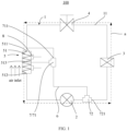
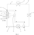
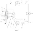
- FIG. 1 to FIG. 7 are schematic structural diagrams of a refrigerator cooling system according to some embodiments of the present invention.
- the refrigerator cooling system 100 includes a refrigerant circulation flow path 1.
- the refrigerant circulation flow path 1 is provided with a compressor 2, a condenser 3, a throttling device 4 and an evaporator 5.
- the evaporator 5 includes a heat exchange core tube 51.
- the heat exchange core tube 51 includes a main inlet 511 communicated with the throttling device 4 and a main outlet 512 communicated with the compressor 2.
- a middle section of the heat exchange core tube 51 is provided with at least one middle inlet 513.
- a section of the refrigerant circulation flow path 1 between an exhaust port of the compressor 2 and the main inlet 511 of the evaporator 5 is a first flow path section 11.
- the refrigerator cooling system 100 further includes a defrosting branch 6 and a switching device 7.
- the defrosting branch 6 is connected among the exhaust port of the compressor 2, the main inlet 511 and the at least one middle inlet 513.
- the switching device 7 is for switching the defrosting branch 6 to communicate the exhaust port of the compressor 2 with at least one of the main inlet 511 and the at least one middle inlet 513, to enter a defrosting working mode, and the switching device 7 is further for switching the first flow path section 11 to be in a circulating state, to enter a cooling working mode.
- the heat exchange core tube 51 of the evaporator 5 includes a main inlet 511 communicated with the throttling device 4 and a main outlet 512 communicated with the compressor 2.
- a middle section of the heat exchange core tube 51 is provided with at least one middle inlet 513.
- a section of the refrigerant circulation flow path 1 between an exhaust port of the compressor 2 and the main inlet 511 of the evaporator 5 is a first flow path section 11.
- the defrosting branch 6 is connected among the exhaust port of the compressor 2, the main inlet 511 and the at least one middle inlet 513.
- the switching device 7 switches the defrosting branch 6 to communicate the exhaust port of the compressor 2 with at least one of the main inlet 511 and the at least one middle inlet 513.
- the entire heat exchange core tube 51 is defrosted.
- the heat exchange core tube 51 is defrosted in part.
- the defrosting branch 6 makes the refrigerant not pass through the throttling device 4, and the refrigerant has a higher temperature.
- the defrosting branch 6 can be a plurality of parallel branches. One end of the plurality of branches is used to communicate with the exhaust port of the compressor 2, and the other end is communicated with the main inlet 511 and the at least one middle inlet 513, respectively.
- the switching device 7 only needs to switch one of the branches to conduct, and of course, a plurality of the branches can be conducted at the same time.
- the defrosting branch 6 is a single branch, one end is communicated with the exhaust port of the compressor 2, and the other end can be switched to select different inlets on the heat exchange core tube 51.
- the defrosting branch 6 has one input port and a plurality of output ports. The input port is connected between the exhaust port of the compressor 2 and the condenser 3. The plurality of output ports are respectively provided corresponding to the main inlet 511 and at least one middle inlet 513.
- the switching device 7 includes a first switching device and a second switching device. The first switching device is for switching at least one of the plurality of output ports to communicate with one of the main inlet 511 and the at least one middle inlet 513.
- the second switching device is for switching one of the input port and the first flow path section 11 to communicate with the exhaust port of the compressor 2.
- Both the first switching device and the second switching device can be configured as a valve combination structure, such as two one-way valves arranged in parallel, etc.
- the first switching device includes a first three-way valve 71, the first three-way valve 71 is formed with three first communication ports 711 that communicate with each other, two of the three first communication ports 711 are connected in series between the defrosting branch 6 and the main inlet 511, and the other first communication port 711 is connected to one of the middle inlets 513.
- the first three-way valve 71 realizes switching at least one of the output ports to communicate with the corresponding one of the main inlet 511 and the at least one middle inlet 513, the structure is simple, and the switching is convenient.
- the first switching device When there are a plurality of middle inlets 513, as shown in FIG. 4 to FIG. 7 , the first switching device includes a plurality of first three-way valves 71, two first communication ports 711 of each of the plurality of first three-way valves 71 are connected in series between the defrosting branch 6 and the main inlet 511, and the other communication ports of the plurality of first three-way valves 71 are correspondingly connected to the plurality of middle inlets 513. Each of the first three-way valves 71 switches one of the plurality of output ports to communicate with the corresponding middle inlet 513, which has a simple structure and is convenient for switching.
- the first three-way valve 71 is an electromagnetic three-way valve, which facilitates automatic control of the first three-way valve 71, has a high degree of automation, and improves user experience.
- the second switching device includes a second three-way valve 72, and the second three-way valve 72 is formed with three second communication ports 721 that communicate with each other.
- a first one of the three second communication ports 721 is communicated with the first flow path section 11, a second one of the three second communication ports 721 is communicated with the exhaust port of the compressor 2, and a third one of the three second communication ports 721 is communicated with the defrosting branch 6.
- the second three-way valve 72 realizes switching one of the input port and the first flow path section 11 to communicate with the exhaust port of the compressor 2, which has a simple structure and is convenient for switching.
- the second three-way valve 72 is an electromagnetic three-way valve, which facilitates automatic control of the second three-way valve 72, has a high degree of automation, and improves user experience.
- the switching between the cooling working mode and the defrosting working mode of the refrigerator cooling system 100 may take the time parameter as the reference object. For example, after the refrigerator cooling system operates in the cooling working mode for a period of time, the refrigerator cooling system switches from the cooling working mode to the defrosting working mode. The refrigerator cooling system also switches from the defrosting working mode to the cooling working mode after the refrigerator cooling system operates in the defrosting working mode for a period of time. The switching can also take the temperature parameter as the reference object. For example, when the surface temperature of the evaporator 5 is lower than the first preset temperature after the refrigerator cooling system operates in the cooling working mode for a period of time, the refrigerator cooling system 100 switches from the cooling working mode to the defrosting working mode.
- the refrigerator cooling system 100 switches from the defrosting working mode to the cooling working mode.
- the refrigerator cooling system 100 switches from the defrosting working mode to the cooling working mode.
- the switching device 7 is an electrical switching device.
- the refrigerator cooling system further includes a temperature sensor 8 and a control assembly.
- the temperature sensor 8 is for detecting a surface temperature of the evaporator 5.
- the control assembly is electrically connected to the temperature sensor 8 and the electrical switching device, for switching a working mode of the refrigerator cooling system 100 according to a temperature obtained by the temperature sensor 8. This arrangement enables the refrigerator cooling system 100 to switch between the cooling working mode and the defrosting working mode more intelligently.
- the at least one middle inlet 513 is configured to divide the heat exchange core tube 51 into a plurality of heat exchange sections, and a plurality of the temperature sensors 8 are provided corresponding to the plurality of the heat exchange sections.
- the plurality of the temperature sensors 8 can detect the temperature on the entire length of the heat exchange core tube 51, and the obtained temperature is relatively accurate, which is convenient for controlling the refrigerator cooling system 100 to achieve accurate defrosting.
- the corresponding flow direction of the refrigerant in the refrigerant circulation flow path 1 and the action of the three-way valve illustrate the principle of the refrigerator cooling system 100 switching between the cooling working mode and the defrosting working mode.
- FIG. 8 to FIG. 11 are schematic diagrams of a method for defrosting a refrigerator according to some embodiments of the present invention
- FIG. 8 is a schematic flowchart of a method for defrosting a refrigerator according to a first embodiment of the present invention
- the defrosting working mode includes a full defrosting mode and at least one partial defrosting mode.
- the defrosting branch 6 is communicated with the exhaust port of the compressor 2 and is provided corresponding to the main inlet 511.
- the defrosting branch 6 is communicated with the exhaust port of the compressor 2 and is provided corresponding to the middle inlet 513.
- the method for defrosting the refrigerator includes following operations: S1, obtaining a first working parameter of the refrigerator cooling system in response to the refrigerator cooling system 100 being in the cooling working mode.
- the cooling system of the refrigerator needs to provide cooling capacity for the refrigerating chamber and the freezing chamber. After a long time of operation, the refrigerator will form frost, and the thickness of the frost on core tubes of the evaporator 5 is not uniform.
- the first working parameter includes a temperature parameter and a working duration parameter.
- the time parameter is used as the reference object, for example, after the refrigerator cooling system operates in the cooling working mode for a period of time, the refrigerator cooling system switches from the cooling working mode to the defrosting working mode.
- the refrigerator cooling system can switch from the defrosting mode to the cooling working mode after operating in the defrosting working mode for a period of time.
- the temperature parameter may also be the reference object. For example, when the temperature of the evaporator 5 is lower than the preset temperature value, the cooling working mode is switched to the defrosting working mode. When the temperature of the evaporator 5 is greater than a preset temperature value, the defrosting working mode is switched to the cooling working mode.
- the refrigerator when the time parameter is used as the reference object, after the refrigerator works for a long time, the refrigerator will be frosted, and it needs to be defrosted at this time. It is possible to set a preset duration to start the defrosting mode of the refrigerator, such as 6h, 8h, 10h, 12h, or the like. It can also be considered according to the actual working environment of the refrigerator, such as humidity environment. Different humidity environments corresponding to different preset durations. When the actual duration reaches the preset duration, the defrosting working mode can be automatically started to perform the defrosting operation on the refrigerator. In addition, if the duration parameter reaches 6 hours, the refrigerator cooling system 100 is switched to enter the partial defrosting mode, and when the duration parameter reaches 8 hours, the refrigerator cooling system 100 is switched to enter the full defrosting mode.
- a preset duration to start the defrosting mode of the refrigerator, such as 6h, 8h, 10h, 12h, or the like. It can also be considered according to the actual working environment of the refrigerator, such as
- the first working parameter of the refrigerator cooling system 100 is obtained.
- the refrigerator cooling system 100 is switched to enter the full defrosting mode and the partial defrosting mode according to the first working parameter.
- the evaporator 5 is defrosted in stages, the defrosting control is precise, the defrosting efficiency is increased, the energy consumption of defrosting is reduced, and the user experience is improved.
- FIG. 9 is a schematic flowchart of a method for defrosting a refrigerator according to a second embodiment of the present invention
- the first working parameter is an actual working duration parameter T.
- the method further includes the following operations:
- T2 is a specific value smaller than T1, for example, when T1 is 10h, T2 may be 6h or 8h, and so on.
- the preset condition may be satisfying a time condition, or satisfying a temperature condition, and so on.
- the heat exchange core tube 51 of the evaporator 5 When the refrigerator cooling system 100 works for a short period of time, the heat exchange core tube 51 of the evaporator 5 is partially frosted, and it is only necessary to defrost the part that is prone to frost.
- the heat exchange core tube 51 of the evaporator 5 When the refrigerator cooling system 100 works for a long time, the heat exchange core tube 51 of the evaporator 5 will be frosted as a whole, and the entire heat exchange core tube 51 needs to be defrosted.
- the evaporator 5 is defrosted in stages, the defrosting control is precise, the defrosting efficiency is increased, the energy consumption of defrosting is reduced, and the user experience is improved.
- FIG. 10 is a schematic flowchart of a method for defrosting a refrigerator according to a third embodiment of the present invention
- a plurality of middle inlets 513 are provided, the plurality of middle inlets 513 include a first middle inlet away from the main inlet 511 and a second middle inlet adjacent to the main inlet 511.
- the partial defrosting mode includes a first partial defrosting mode and a second partial defrosting mode.
- the defrosting branch 6 is communicated with the exhaust port of the compressor 2 and the first middle inlet.
- the defrosting branch 6 is communicated with the exhaust port of the compressor 2 and the second middle inlet.
- the method further includes the following operations: S211, when T is equal to T21, switching the refrigerator cooling system to enter the first partial defrosting mode, and when the preset condition is reached, switching the refrigerator cooling system from the first partial defrosting mode to the cooling working mode, wherein T21 is a preset cooling duration for a first partial defrosting, and T21 is less than T1.
- the preset condition may be satisfying a time condition, or satisfying a temperature condition, and so on.
- the preset condition may be satisfying a time condition, or satisfying a temperature condition, and so on.
- the heat exchange core tube 51 is divided more accurately, and the defrosting is more accurately segmented. After a period of time, it is possible to defrost the parts that are more prone to frost. After a long period of time, the heat exchange core tube 51 is defrosted as a whole, the defrosting control is precise, the defrosting efficiency is increased, the energy consumption of defrosting is reduced, and the user experience is improved.
- FIG. 11 is a schematic flowchart of a method for defrosting a refrigerator according to a fourth embodiment of the present invention
- the method further includes the following operations: S23, obtaining a second working parameter of the refrigerator cooling system.
- the second working parameter includes a temperature parameter and a working duration parameter.
- the second working parameter of the refrigerator cooling system 100 needs to be obtained, and when the second working parameter reaches the parameter preset value, the mode is switched.
- the second working parameter is the actual temperature parameter t of the evaporator 5, and the preset condition is that t is equal to 11, t1 is the temperature preset value.
- the evaporator 5 provides cold energy to the refrigerator chamber and the freezing chamber of the refrigerator. During the long-term operation of the evaporator 5, frost will form on the part of the evaporator 5 correspondingly.
- the degree of frost formation in the refrigerator can be known by detecting the surface temperature of the evaporator 5 of the refrigerator, which is usually the surface temperature of the evaporator 5 obtained by the temperature sensor 8.
- each length of the heat exchange section is provided with a temperature sensor 8.
- the temperature conditions of multiple temperature sensors 8 can be considered at the same time.
- the refrigerator cooling system 100 when the refrigerator cooling system 100 is in the full defrosting mode, it can be considered that when the temperature of the temperature sensor 8 on each of the heat exchange sections reaches the preset temperature, it switches to the cooling working mode.
- the refrigerator cooling system 100 when the refrigerator cooling system 100 is in the partial defrosting mode, it may be considered that when the temperature of the temperature sensor 8 on the heat exchange section for the local circulating refrigerant reaches the preset temperature, it switches to the cooling working mode.
Landscapes
- Engineering & Computer Science (AREA)
- Physics & Mathematics (AREA)
- Mechanical Engineering (AREA)
- Thermal Sciences (AREA)
- General Engineering & Computer Science (AREA)
- Chemical & Material Sciences (AREA)
- Combustion & Propulsion (AREA)
- Defrosting Systems (AREA)
Claims (15)
- Kühlschrank-Kühlsystem (100), umfassend:einen Kältemittelkreislaufströmungspfad (1), der mit einem Kompressor (2), einem Kondensator (3), einer Drosselvorrichtung (4) und einem Verdampfer (5) versehen ist;einen Abtauzweig (6); undeine Schaltvorrichtung (7),wobei:der Verdampfer (5) ein Wärmeaustauschkernrohr (51) umfasst,das Wärmeaustauschkernrohr (51) einen Haupteinlass (511) umfasst, der mit der Drosselvorrichtung (4) in Verbindung steht, und einen Hauptauslass (512), der mit dem Kompressor (2) in Verbindung steht,ein mittlerer Abschnitt des Wärmeaustauschkernrohrs (51) mit mindestens einem mittleren Einlass (513) versehen ist,ein Abschnitt des Kältemittelkreislaufströmungspfads (1) zwischen einer Abluftöffnung des Kompressors (2) und dem Haupteinlass (511) des Verdampfers (5) ein erster Strömungspfadabschnitt (11) ist,wobei sich sowohl der Kondensator (3) als auch die Drosseleinrichtung (4) auf dem ersten Strömungspfadabschnitt (11) befinden,der Abtauzweig (6) mit der Abluftöffnung des Kompressors (2), dem Haupteinlass (511) und dem mindestens einen mittleren Einlass (513) verbunden ist,die Schaltvorrichtung (7) dazu dient, den Abtauzweig (6) so zu schalten, dass er die Abluftöffnung des Kompressors (2) mit mindestens einem der folgenden Anschlüsse verbindet: dem Haupteinlass (511) und dem mindestens einen mittleren Einlass (513), um in einen Abtauarbeitsmodus zu gelangen, unddie Schaltvorrichtung (7) ferner dazu dient, den ersten Strömungspfadabschnitt (11) in einen Zirkulationszustand zu schalten, um in einen Kühlarbeitsmodus einzutreten.
- Kühlschrank-Kühlsystem (100) gemäß Anspruch 1, wobei:der Abtauzweig (6) einen Eingangsanschluss und eine Vielzahl von Ausgangsanschlüssen aufweist,der Eingangsanschluss zwischen der Abluftöffnung des Kompressors (2) und dem Kondensator (3) verbunden ist,die Vielzahl der Ausgangsanschlüsse jeweils entsprechend dem Haupteinlass (511) und mindestens einem mittleren Einlass (513) vorgesehen sind,die Schaltvorrichtung (7) eine erste Schaltvorrichtung (7) und eine zweite Schaltvorrichtung (7) umfasst,wobei die erste Schaltvorrichtung (7) dazu dient, mindestens einen der Vielzahl von Ausgangsanschlüssen so zu schalten, dass er entweder mit einem entsprechenden Haupteinlass (511) oder dem mindestens einen mittleren Einlass (513) verbunden ist, unddie zweite Schaltvorrichtung (7) dazu dient, entweder den Eingangsanschluss oder den ersten Strömungspfadabschnitt (11) so zu schalten, dass er mit der Abluftöffnung des Kompressors (2) in Verbindung steht.
- Kühlschrank-Kühlsystem (100) gemäß Anspruch 2, wobei die erste Schaltvorrichtung (7) ein erstes Dreiwegeventil (71) umfasst, wobei das erste Dreiwegeventil (71) mit drei ersten Verbindungsanschlüssen (711) ausgebildet ist, die miteinander in Verbindung stehen, wobei zwei der drei ersten Verbindungsanschlüsse (711) in Reihe zwischen dem Abtauzweig (6) und dem Haupteinlass (511) geschaltet sind, und der andere erste Verbindungsanschluss (711) mit einem der mittleren Einlässe (513) verbunden ist.
- Kühlschrank-Kühlsystem (100) gemäß Anspruch 3, wobei:der mittlere Abschnitt des Wärmeaustauschkernrohrs (51) mit einer Vielzahl von mittleren Einlässen (513) versehen ist,die erste Schaltvorrichtung (7) eine Vielzahl von ersten Dreiwegeventilen (71) umfasst,zwei erste Verbindungsanschlüsse (711) jedes der Vielzahl von ersten Dreiwegeventilen (71) zwischen dem Abtauzweig (6) und dem Haupteinlass (511) in Reihe geschaltet sind, unddie anderen Verbindungsanschlüsse der Vielzahl von ersten Dreiwegeventilen (71) entsprechend mit der Vielzahl von mittleren Einlässen (513) verbunden sind.
- Kühlschrank-Kühlsystem (100) gemäß Anspruch 3, wobei das erste Dreiwegeventil (71) ein elektromagnetisches Dreiwegeventil ist.
- Kühlschrank-Kühlsystem (100) gemäß Anspruch 2, wobei:die zweite Schaltvorrichtung (7) ein zweites Dreiwegeventil (72) umfasst, wobei das zweite Dreiwegeventil (72) mit drei zweiten Verbindungsanschlüssen (721) ausgebildet ist, die miteinander in Verbindung stehen, undein erster der drei zweiten Verbindungsanschlüsse (721) mit dem ersten Strömungspfadabschnitt (11) verbunden ist, ein zweiter der drei zweiten Verbindungsanschlüsse (721) mit der Abluftöffnung des Kompressors (2) verbunden ist und ein dritter der drei zweiten Verbindungsanschlüsse (721) mit dem Abtauzweig (6) verbunden ist.
- Kühlschrank-Kühlsystem (100) gemäß Anspruch 6, wobei das zweite Dreiwegeventil (72) ein elektromagnetisches Dreiwegeventil ist.
- Kühlschrank-Kühlsystem (100) gemäß Anspruch 1, wobei die Schaltvorrichtung (7) eine elektrische Schaltvorrichtung (7) ist und das Kühlschrank-Kühlsystem (100) ferner Folgendes umfasst:einen Temperatursensor (8) zum Erfassen einer Oberflächentemperatur des Verdampfers (5); undeine Steueranordnung, die elektrisch mit dem Temperatursensor (8) und der elektrischen Schaltvorrichtung (7) verbunden ist, um einen Arbeitsmodus des Kühlschrank-Kühlsystems (100) gemäß einer durch den Temperatursensor (8) erhaltenen Temperatur zu schalten.
- Kühlschrank-Kühlsystem (100) gemäß Anspruch 8, wobei der mindestens eine mittlere Einlass (513) so konfiguriert ist, dass er das Wärmeaustauschkernrohr (51) in eine Vielzahl von Wärmeaustauschabschnitten unterteilt, und eine Vielzahl von Temperatursensoren (8) entsprechend der Vielzahl von Wärmeaustauschabschnitten vorgesehen sind.
- Verfahren zum Abtauen eines Kühlschranks, das auf ein Kühlschrank-Kühlsystem (100) gemäß einem der Ansprüche 1 bis 9 angewendet wird, wobei:ein Abtau-Betriebmodus einen Vollabtaumodus und zumindest einen Teilabtaumodus umfasst,als Reaktion darauf, dass sich das Kühlschrank-Kühlsystem (100) im Vollabtaumodus befindet, ein Abtauzweig (6) mit einer Abluftöffnung eines Kompressors (2) und einem Haupteinlass (511) verbunden ist,als Reaktion darauf, dass sich das Kühlschrank-Kühlsystem (100) im Teilabtaumodus befindet, der Abtauzweig (6) mit der Abluftöffnung des Kompressors (2) und einem mittleren Einlass (513) verbunden ist,das Verfahren zum Abtauen des Kühlschranks die folgenden Schritte umfasst:(51) Erhalten eines ersten Arbeitsparameters des Kühlschrank-Kühlsystems (100) als Reaktion darauf, dass sich das Kühlschrank-Kühlsystem (100) in dem Kühlarbeitsmodus befindet; und(S2) Umschalten des Kühlschrank-Kühlsystems (100), so dass es in den Vollabtaumodus und in den Teilabtaumodus gemäß dem ersten Arbeitsparameter eintritt.
- Verfahren zum Abtauen des Kühlschranks gemäß Anspruch 10, wobei der erste Arbeitsparameter ein Parameter für die tatsächliche Arbeitsdauer T ist, und der Vorgang (S2) des Umschaltens des Kühlschrank-Kühlsystems (100), so dass es in den Vollabtaumodus und den Teilabtaumodus gemäß dem ersten Arbeitsparameter eintritt, Folgendes umfasst:(S21) wenn T gleich T2 ist, Umschalten des Kühlschrank-Kühlsystems (100), so dass es in den Teilabtaumodus eintritt, und wenn eine voreingestellte Bedingung erreicht ist, Umschalten des Kühlschrank-Kühlsystems (100) von dem Teilabtaumodus in den Kühlarbeitsmodus, wobei T2 eine voreingestellte Kühldauer für das Teilabtauen ist; und(S22), wenn T gleich T1 ist, Umschalten des Kühlschrank-Kühlsystems (100), so dass es in den Vollabtaumodus eintritt, wobei T1 eine voreingestellte Kühldauer für das Vollabtauen ist und T1 größer als T2 ist.
- Verfahren zum Abtauen des Kühlschranks gemäß Anspruch 11, wobei eine Vielzahl von mittleren Einlässen (513) vorgesehen ist, wobei die Vielzahl von mittleren Einlässen (513) einen ersten mittleren Einlass (513), der vom Haupteinlass (511) entfernt ist, und einen zweiten mittleren Einlass (513), der an den Haupteinlass (511) angrenzt, umfassen, wobei der Teilabtaumodus einen ersten Teilabtaumodus und einen zweiten Teilabtaumodus umfasst,als Reaktion darauf, dass sich das Kühlschrank-Kühlsystem (100) im ersten Teilabtaumodus befindet, der Abtauzweig (6) mit der Abluftöffnung des Kompressors (2) und dem ersten mittleren Einlass (513) verbunden ist,als Reaktion darauf, dass sich das Kühlschrank-Kühlsystem (100) im zweiten Teilabtaumodus befindet, der Abtauzweig (6) mit der Abluftöffnung des Kompressors (2) und dem zweiten mittleren Einlass (513) verbunden ist,der Vorgang von (S21), wenn T gleich T2 ist, Umschalten des Kühlschrank-Kühlsystems (100), so dass es in den Teilabtaumodus eintritt, und wenn die voreingestellte Bedingung erreicht ist, Umschalten des Kühlschrank-Kühlsystems (100) von dem Teilabtaumodus in den Kühlarbeitsmodus, Folgendes umfasst:(S211) wenn T gleich T21 ist, Umschalten des Kühlschrank-Kühlsystems (100), so dass es in den ersten Teilabtaumodus eintritt, und wenn die voreingestellte Bedingung erreicht ist, Umschalten des Kühlschrank-Kühlsystems (100) von dem ersten Teilabtaumodus in den Kühlarbeitsmodus, wobei T21 eine voreingestellte Kühldauer für ein erstes Teilabtauen ist und T21 kleiner als T1 ist; und(S212), wenn T gleich T22 ist, Umschalten des Kühlschrank-Kühlsystems (100), so dass es in den zweiten Teilabtaumodus eintritt, und wenn die voreingestellte Bedingung erreicht ist, Umschalten des Kühlschrank-Kühlsystems (100) vom zweiten Teilabtaumodus in den Kühlarbeitsmodus, wobei T22 eine voreingestellte Kühldauer für ein zweites Teilabtauen ist und T22 kleiner als T1 und größer als T21 ist.
- Verfahren zum Abtauen des Kühlschranks gemäß Anspruch 11, wobei der Vorgang (S21), wenn T gleich T2 ist, Umschalten des Kühlschrank-Kühlsystems (100), so dass es in den Teilabtaumodus eintritt, und, wenn die voreingestellte Bedingung erreicht ist, Umschalten des Kühlschrank-Kühlsystems (100) vom Teilabtaumodus in den Kühlarbeitsmodus, ferner Folgendes umfasst:(S23) Erhalten eines zweiten Arbeitsparameters des Kühlschrank-Kühlsystems (100),wobei die voreingestellte Bedingung darin besteht, dass der zweite Arbeitsparameter einen voreingestellten Parameterwert erreicht.
- Verfahren zum Abtauen des Kühlschranks gemäß Anspruch 13, wobei der zweite Arbeitsparameter ein tatsächlicher Temperaturparameter t des Verdampfers (5) ist, die voreingestellte Bedingung ist, dass t gleich t1 ist, und t1 ein voreingestellter Temperaturwert ist.
- Verfahren zum Abtauen des Kühlschranks gemäß Anspruch 13, wobei der erste Arbeitsparameter und/oder der zweite Arbeitsparameter einen Temperaturparameter und einen Arbeitsdauerparameter umfasst.
Applications Claiming Priority (2)
| Application Number | Priority Date | Filing Date | Title |
|---|---|---|---|
| CN202011384417.4A CN114576915B (zh) | 2020-11-30 | 2020-11-30 | 冰箱制冷系统及冰箱化霜方法 |
| PCT/CN2021/120991 WO2022111035A1 (zh) | 2020-11-30 | 2021-09-27 | 冰箱制冷系统及冰箱化霜方法 |
Publications (3)
| Publication Number | Publication Date |
|---|---|
| EP4137758A1 EP4137758A1 (de) | 2023-02-22 |
| EP4137758A4 EP4137758A4 (de) | 2023-11-08 |
| EP4137758B1 true EP4137758B1 (de) | 2024-05-15 |
Family
ID=81753984
Family Applications (1)
| Application Number | Title | Priority Date | Filing Date |
|---|---|---|---|
| EP21896537.4A Active EP4137758B1 (de) | 2020-11-30 | 2021-09-27 | Kühlschrankkühlsystem und enteisenverfahren für kühlschrank |
Country Status (4)
| Country | Link |
|---|---|
| US (1) | US12560372B2 (de) |
| EP (1) | EP4137758B1 (de) |
| CN (1) | CN114576915B (de) |
| WO (1) | WO2022111035A1 (de) |
Families Citing this family (2)
| Publication number | Priority date | Publication date | Assignee | Title |
|---|---|---|---|---|
| CN117781510A (zh) * | 2024-01-04 | 2024-03-29 | 中绅科技(广东)有限公司 | 一种新型热泵化霜结构的制冷化霜控制方法 |
| CN117824180A (zh) * | 2024-02-06 | 2024-04-05 | 华域三电汽车空调有限公司 | 一种间接热泵系统及使用方法 |
Family Cites Families (15)
| Publication number | Priority date | Publication date | Assignee | Title |
|---|---|---|---|---|
| US4565070A (en) * | 1983-06-01 | 1986-01-21 | Carrier Corporation | Apparatus and method for defrosting a heat exchanger in a refrigeration circuit |
| CN101509718B (zh) * | 2009-03-23 | 2010-10-13 | 合肥美的荣事达电冰箱有限公司 | 风冷冰箱自动化霜系统 |
| KR20120012613A (ko) | 2010-08-02 | 2012-02-10 | 삼성전자주식회사 | 냉장고 및 그 제어방법 |
| WO2015149840A1 (en) * | 2014-03-31 | 2015-10-08 | Arcelik Anonim Sirketi | Refrigeration appliance provided with an improved defrost circuit |
| CN204787467U (zh) * | 2015-05-14 | 2015-11-18 | 浙江蔚庭新能源科技有限公司 | 一种高效除霜型热泵 |
| KR102480701B1 (ko) * | 2015-07-28 | 2022-12-23 | 엘지전자 주식회사 | 냉장고 |
| US10634391B2 (en) * | 2016-10-13 | 2020-04-28 | Johnson Controls Technology Company | Supplemental heating and cooling system |
| CN206488502U (zh) * | 2016-11-22 | 2017-09-12 | 珠海格力电器股份有限公司 | 一种空调机组 |
| CN106440462A (zh) * | 2016-11-22 | 2017-02-22 | 珠海格力电器股份有限公司 | 一种空调机组和空调机组的控制方法 |
| CN107152820B (zh) * | 2017-06-19 | 2020-05-29 | 青岛海尔空调器有限总公司 | 一种空调器及其控制方法 |
| EP3781875A4 (de) * | 2018-04-20 | 2022-03-30 | Okanagan Winery & Ciders | Kondensationsentfeuchter für eine arena oder dergleichen |
| CN208704226U (zh) * | 2018-08-20 | 2019-04-05 | 泗县格雷制冷设备有限公司 | 一种空气源热泵分路化霜系统 |
| DE102019200673A1 (de) * | 2019-01-21 | 2020-07-23 | BSH Hausgeräte GmbH | Kältegerät mit automatisch abtaubarem Verdampfer |
| CN111520942B (zh) * | 2020-05-06 | 2021-02-23 | 珠海格力电器股份有限公司 | 冰箱 |
| US11512901B2 (en) * | 2020-09-25 | 2022-11-29 | Rheem Manufacturing Company | Adjustable capacity heat exchanger |
-
2020
- 2020-11-30 CN CN202011384417.4A patent/CN114576915B/zh active Active
-
2021
- 2021-09-27 WO PCT/CN2021/120991 patent/WO2022111035A1/zh not_active Ceased
- 2021-09-27 US US18/003,664 patent/US12560372B2/en active Active
- 2021-09-27 EP EP21896537.4A patent/EP4137758B1/de active Active
Also Published As
| Publication number | Publication date |
|---|---|
| CN114576915A (zh) | 2022-06-03 |
| EP4137758A4 (de) | 2023-11-08 |
| US20230288122A1 (en) | 2023-09-14 |
| WO2022111035A1 (zh) | 2022-06-02 |
| US12560372B2 (en) | 2026-02-24 |
| CN114576915B (zh) | 2023-06-30 |
| EP4137758A1 (de) | 2023-02-22 |
Similar Documents
| Publication | Publication Date | Title |
|---|---|---|
| US6393858B1 (en) | Refrigeration system | |
| EP3745051A1 (de) | Kältekreislaufvorrichtung | |
| CN111238155B (zh) | 一种三温区双系统冰箱的控制及制冷方法 | |
| EP2325576A1 (de) | Tiefkühlvorrichtung | |
| CN104654461A (zh) | 一种可连续制热化霜的空调器及其控制方法 | |
| CN106871477A (zh) | 除霜装置、热泵机组及其除霜方法 | |
| EP2891849A1 (de) | Wärmerückgewinnung für eine Multifunktionswärmepumpe und Multifunktionsklimaanlage | |
| CN112902478B (zh) | 空调换热结构、空调外机、空调系统及空调系统控制方法 | |
| JPH0762569B2 (ja) | 空気調和装置の運転制御装置 | |
| EP4137758A1 (de) | Kühlschrankkühlsystem und enteisenverfahren für kühlschrank | |
| CN111520956A (zh) | 一种双系统冰箱及其化霜控制方法 | |
| CN104896581A (zh) | 空调器及空调器的控制方法 | |
| EP4119866A1 (de) | Partitionsgesteuertes mehrleitungssystem und selbstidentifikationssteuerungsverfahren davon | |
| WO2008091109A1 (en) | Method and apparatus for defrosting | |
| CN110319542B (zh) | 一种大排量变频多联机系统的卸载启闭控制方法 | |
| CN108507237A (zh) | 一种数据中心制冷系统 | |
| CN214581889U (zh) | 一种空调换热结构、空调外机及空调系统 | |
| CN215002360U (zh) | 冰箱的冷热两用压缩系统及冰箱 | |
| CN119554749A (zh) | 用于控制空调器的方法及装置、空调器、存储介质 | |
| CN116294275A (zh) | 一种带自动除霜功能的制冷系统 | |
| CN211876411U (zh) | 连续制热的空调机组 | |
| EP4134604A1 (de) | Kühlsystem für einen kühlschrank und abtauverfahren für einen kühlschrank | |
| US20190008289A1 (en) | Refrigeration display case | |
| CN208887150U (zh) | 一种能防止室外换热器结霜的热泵系统 | |
| CN214371043U (zh) | 冰箱的压缩制冷系统及冰箱 |
Legal Events
| Date | Code | Title | Description |
|---|---|---|---|
| STAA | Information on the status of an ep patent application or granted ep patent |
Free format text: STATUS: THE INTERNATIONAL PUBLICATION HAS BEEN MADE |
|
| PUAI | Public reference made under article 153(3) epc to a published international application that has entered the european phase |
Free format text: ORIGINAL CODE: 0009012 |
|
| STAA | Information on the status of an ep patent application or granted ep patent |
Free format text: STATUS: REQUEST FOR EXAMINATION WAS MADE |
|
| 17P | Request for examination filed |
Effective date: 20221115 |
|
| AK | Designated contracting states |
Kind code of ref document: A1 Designated state(s): AL AT BE BG CH CY CZ DE DK EE ES FI FR GB GR HR HU IE IS IT LI LT LU LV MC MK MT NL NO PL PT RO RS SE SI SK SM TR |
|
| A4 | Supplementary search report drawn up and despatched |
Effective date: 20231009 |
|
| RIC1 | Information provided on ipc code assigned before grant |
Ipc: F25D 21/00 20060101ALI20231002BHEP Ipc: F25B 49/02 20060101ALI20231002BHEP Ipc: F25B 41/20 20210101ALI20231002BHEP Ipc: F25D 21/06 20060101ALI20231002BHEP Ipc: F25B 47/02 20060101AFI20231002BHEP |
|
| GRAP | Despatch of communication of intention to grant a patent |
Free format text: ORIGINAL CODE: EPIDOSNIGR1 |
|
| STAA | Information on the status of an ep patent application or granted ep patent |
Free format text: STATUS: GRANT OF PATENT IS INTENDED |
|
| DAV | Request for validation of the european patent (deleted) | ||
| DAX | Request for extension of the european patent (deleted) | ||
| INTG | Intention to grant announced |
Effective date: 20240228 |
|
| GRAS | Grant fee paid |
Free format text: ORIGINAL CODE: EPIDOSNIGR3 |
|
| GRAA | (expected) grant |
Free format text: ORIGINAL CODE: 0009210 |
|
| STAA | Information on the status of an ep patent application or granted ep patent |
Free format text: STATUS: THE PATENT HAS BEEN GRANTED |
|
| AK | Designated contracting states |
Kind code of ref document: B1 Designated state(s): AL AT BE BG CH CY CZ DE DK EE ES FI FR GB GR HR HU IE IS IT LI LT LU LV MC MK MT NL NO PL PT RO RS SE SI SK SM TR |
|
| REG | Reference to a national code |
Ref country code: CH Ref legal event code: EP |
|
| REG | Reference to a national code |
Ref country code: IE Ref legal event code: FG4D |
|
| REG | Reference to a national code |
Ref country code: DE Ref legal event code: R096 Ref document number: 602021013426 Country of ref document: DE |
|
| REG | Reference to a national code |
Ref country code: LT Ref legal event code: MG9D |
|
| REG | Reference to a national code |
Ref country code: NL Ref legal event code: MP Effective date: 20240515 |
|
| PG25 | Lapsed in a contracting state [announced via postgrant information from national office to epo] |
Ref country code: IS Free format text: LAPSE BECAUSE OF FAILURE TO SUBMIT A TRANSLATION OF THE DESCRIPTION OR TO PAY THE FEE WITHIN THE PRESCRIBED TIME-LIMIT Effective date: 20240915 |
|
| PG25 | Lapsed in a contracting state [announced via postgrant information from national office to epo] |
Ref country code: BG Free format text: LAPSE BECAUSE OF FAILURE TO SUBMIT A TRANSLATION OF THE DESCRIPTION OR TO PAY THE FEE WITHIN THE PRESCRIBED TIME-LIMIT Effective date: 20240515 |
|
| PG25 | Lapsed in a contracting state [announced via postgrant information from national office to epo] |
Ref country code: HR Free format text: LAPSE BECAUSE OF FAILURE TO SUBMIT A TRANSLATION OF THE DESCRIPTION OR TO PAY THE FEE WITHIN THE PRESCRIBED TIME-LIMIT Effective date: 20240515 Ref country code: FI Free format text: LAPSE BECAUSE OF FAILURE TO SUBMIT A TRANSLATION OF THE DESCRIPTION OR TO PAY THE FEE WITHIN THE PRESCRIBED TIME-LIMIT Effective date: 20240515 |
|
| PG25 | Lapsed in a contracting state [announced via postgrant information from national office to epo] |
Ref country code: GR Free format text: LAPSE BECAUSE OF FAILURE TO SUBMIT A TRANSLATION OF THE DESCRIPTION OR TO PAY THE FEE WITHIN THE PRESCRIBED TIME-LIMIT Effective date: 20240816 |
|
| PG25 | Lapsed in a contracting state [announced via postgrant information from national office to epo] |
Ref country code: PT Free format text: LAPSE BECAUSE OF FAILURE TO SUBMIT A TRANSLATION OF THE DESCRIPTION OR TO PAY THE FEE WITHIN THE PRESCRIBED TIME-LIMIT Effective date: 20240916 |
|
| REG | Reference to a national code |
Ref country code: AT Ref legal event code: MK05 Ref document number: 1687220 Country of ref document: AT Kind code of ref document: T Effective date: 20240515 |
|
| PG25 | Lapsed in a contracting state [announced via postgrant information from national office to epo] |
Ref country code: NL Free format text: LAPSE BECAUSE OF FAILURE TO SUBMIT A TRANSLATION OF THE DESCRIPTION OR TO PAY THE FEE WITHIN THE PRESCRIBED TIME-LIMIT Effective date: 20240515 |
|
| PG25 | Lapsed in a contracting state [announced via postgrant information from national office to epo] |
Ref country code: ES Free format text: LAPSE BECAUSE OF FAILURE TO SUBMIT A TRANSLATION OF THE DESCRIPTION OR TO PAY THE FEE WITHIN THE PRESCRIBED TIME-LIMIT Effective date: 20240515 |
|
| PG25 | Lapsed in a contracting state [announced via postgrant information from national office to epo] |
Ref country code: AT Free format text: LAPSE BECAUSE OF FAILURE TO SUBMIT A TRANSLATION OF THE DESCRIPTION OR TO PAY THE FEE WITHIN THE PRESCRIBED TIME-LIMIT Effective date: 20240515 |
|
| PG25 | Lapsed in a contracting state [announced via postgrant information from national office to epo] |
Ref country code: PL Free format text: LAPSE BECAUSE OF FAILURE TO SUBMIT A TRANSLATION OF THE DESCRIPTION OR TO PAY THE FEE WITHIN THE PRESCRIBED TIME-LIMIT Effective date: 20240515 |
|
| PG25 | Lapsed in a contracting state [announced via postgrant information from national office to epo] |
Ref country code: LV Free format text: LAPSE BECAUSE OF FAILURE TO SUBMIT A TRANSLATION OF THE DESCRIPTION OR TO PAY THE FEE WITHIN THE PRESCRIBED TIME-LIMIT Effective date: 20240515 |
|
| PG25 | Lapsed in a contracting state [announced via postgrant information from national office to epo] |
Ref country code: PT Free format text: LAPSE BECAUSE OF FAILURE TO SUBMIT A TRANSLATION OF THE DESCRIPTION OR TO PAY THE FEE WITHIN THE PRESCRIBED TIME-LIMIT Effective date: 20240916 Ref country code: PL Free format text: LAPSE BECAUSE OF FAILURE TO SUBMIT A TRANSLATION OF THE DESCRIPTION OR TO PAY THE FEE WITHIN THE PRESCRIBED TIME-LIMIT Effective date: 20240515 Ref country code: NO Free format text: LAPSE BECAUSE OF FAILURE TO SUBMIT A TRANSLATION OF THE DESCRIPTION OR TO PAY THE FEE WITHIN THE PRESCRIBED TIME-LIMIT Effective date: 20240815 Ref country code: NL Free format text: LAPSE BECAUSE OF FAILURE TO SUBMIT A TRANSLATION OF THE DESCRIPTION OR TO PAY THE FEE WITHIN THE PRESCRIBED TIME-LIMIT Effective date: 20240515 Ref country code: LV Free format text: LAPSE BECAUSE OF FAILURE TO SUBMIT A TRANSLATION OF THE DESCRIPTION OR TO PAY THE FEE WITHIN THE PRESCRIBED TIME-LIMIT Effective date: 20240515 Ref country code: IS Free format text: LAPSE BECAUSE OF FAILURE TO SUBMIT A TRANSLATION OF THE DESCRIPTION OR TO PAY THE FEE WITHIN THE PRESCRIBED TIME-LIMIT Effective date: 20240915 Ref country code: HR Free format text: LAPSE BECAUSE OF FAILURE TO SUBMIT A TRANSLATION OF THE DESCRIPTION OR TO PAY THE FEE WITHIN THE PRESCRIBED TIME-LIMIT Effective date: 20240515 Ref country code: GR Free format text: LAPSE BECAUSE OF FAILURE TO SUBMIT A TRANSLATION OF THE DESCRIPTION OR TO PAY THE FEE WITHIN THE PRESCRIBED TIME-LIMIT Effective date: 20240816 Ref country code: FI Free format text: LAPSE BECAUSE OF FAILURE TO SUBMIT A TRANSLATION OF THE DESCRIPTION OR TO PAY THE FEE WITHIN THE PRESCRIBED TIME-LIMIT Effective date: 20240515 Ref country code: ES Free format text: LAPSE BECAUSE OF FAILURE TO SUBMIT A TRANSLATION OF THE DESCRIPTION OR TO PAY THE FEE WITHIN THE PRESCRIBED TIME-LIMIT Effective date: 20240515 Ref country code: BG Free format text: LAPSE BECAUSE OF FAILURE TO SUBMIT A TRANSLATION OF THE DESCRIPTION OR TO PAY THE FEE WITHIN THE PRESCRIBED TIME-LIMIT Effective date: 20240515 Ref country code: AT Free format text: LAPSE BECAUSE OF FAILURE TO SUBMIT A TRANSLATION OF THE DESCRIPTION OR TO PAY THE FEE WITHIN THE PRESCRIBED TIME-LIMIT Effective date: 20240515 Ref country code: RS Free format text: LAPSE BECAUSE OF FAILURE TO SUBMIT A TRANSLATION OF THE DESCRIPTION OR TO PAY THE FEE WITHIN THE PRESCRIBED TIME-LIMIT Effective date: 20240815 |
|
| PG25 | Lapsed in a contracting state [announced via postgrant information from national office to epo] |
Ref country code: DK Free format text: LAPSE BECAUSE OF FAILURE TO SUBMIT A TRANSLATION OF THE DESCRIPTION OR TO PAY THE FEE WITHIN THE PRESCRIBED TIME-LIMIT Effective date: 20240515 |
|
| PG25 | Lapsed in a contracting state [announced via postgrant information from national office to epo] |
Ref country code: EE Free format text: LAPSE BECAUSE OF FAILURE TO SUBMIT A TRANSLATION OF THE DESCRIPTION OR TO PAY THE FEE WITHIN THE PRESCRIBED TIME-LIMIT Effective date: 20240515 |
|
| PG25 | Lapsed in a contracting state [announced via postgrant information from national office to epo] |
Ref country code: CZ Free format text: LAPSE BECAUSE OF FAILURE TO SUBMIT A TRANSLATION OF THE DESCRIPTION OR TO PAY THE FEE WITHIN THE PRESCRIBED TIME-LIMIT Effective date: 20240515 |
|
| PG25 | Lapsed in a contracting state [announced via postgrant information from national office to epo] |
Ref country code: SK Free format text: LAPSE BECAUSE OF FAILURE TO SUBMIT A TRANSLATION OF THE DESCRIPTION OR TO PAY THE FEE WITHIN THE PRESCRIBED TIME-LIMIT Effective date: 20240515 Ref country code: RO Free format text: LAPSE BECAUSE OF FAILURE TO SUBMIT A TRANSLATION OF THE DESCRIPTION OR TO PAY THE FEE WITHIN THE PRESCRIBED TIME-LIMIT Effective date: 20240515 |
|
| PG25 | Lapsed in a contracting state [announced via postgrant information from national office to epo] |
Ref country code: SM Free format text: LAPSE BECAUSE OF FAILURE TO SUBMIT A TRANSLATION OF THE DESCRIPTION OR TO PAY THE FEE WITHIN THE PRESCRIBED TIME-LIMIT Effective date: 20240515 |
|
| PG25 | Lapsed in a contracting state [announced via postgrant information from national office to epo] |
Ref country code: SM Free format text: LAPSE BECAUSE OF FAILURE TO SUBMIT A TRANSLATION OF THE DESCRIPTION OR TO PAY THE FEE WITHIN THE PRESCRIBED TIME-LIMIT Effective date: 20240515 Ref country code: SK Free format text: LAPSE BECAUSE OF FAILURE TO SUBMIT A TRANSLATION OF THE DESCRIPTION OR TO PAY THE FEE WITHIN THE PRESCRIBED TIME-LIMIT Effective date: 20240515 Ref country code: RO Free format text: LAPSE BECAUSE OF FAILURE TO SUBMIT A TRANSLATION OF THE DESCRIPTION OR TO PAY THE FEE WITHIN THE PRESCRIBED TIME-LIMIT Effective date: 20240515 Ref country code: EE Free format text: LAPSE BECAUSE OF FAILURE TO SUBMIT A TRANSLATION OF THE DESCRIPTION OR TO PAY THE FEE WITHIN THE PRESCRIBED TIME-LIMIT Effective date: 20240515 Ref country code: DK Free format text: LAPSE BECAUSE OF FAILURE TO SUBMIT A TRANSLATION OF THE DESCRIPTION OR TO PAY THE FEE WITHIN THE PRESCRIBED TIME-LIMIT Effective date: 20240515 Ref country code: CZ Free format text: LAPSE BECAUSE OF FAILURE TO SUBMIT A TRANSLATION OF THE DESCRIPTION OR TO PAY THE FEE WITHIN THE PRESCRIBED TIME-LIMIT Effective date: 20240515 |
|
| PG25 | Lapsed in a contracting state [announced via postgrant information from national office to epo] |
Ref country code: IT Free format text: LAPSE BECAUSE OF FAILURE TO SUBMIT A TRANSLATION OF THE DESCRIPTION OR TO PAY THE FEE WITHIN THE PRESCRIBED TIME-LIMIT Effective date: 20240515 |
|
| REG | Reference to a national code |
Ref country code: DE Ref legal event code: R097 Ref document number: 602021013426 Country of ref document: DE |
|
| PLBE | No opposition filed within time limit |
Free format text: ORIGINAL CODE: 0009261 |
|
| STAA | Information on the status of an ep patent application or granted ep patent |
Free format text: STATUS: NO OPPOSITION FILED WITHIN TIME LIMIT |
|
| 26N | No opposition filed |
Effective date: 20250218 |
|
| PG25 | Lapsed in a contracting state [announced via postgrant information from national office to epo] |
Ref country code: SI Free format text: LAPSE BECAUSE OF FAILURE TO SUBMIT A TRANSLATION OF THE DESCRIPTION OR TO PAY THE FEE WITHIN THE PRESCRIBED TIME-LIMIT Effective date: 20240515 Ref country code: MC Free format text: LAPSE BECAUSE OF FAILURE TO SUBMIT A TRANSLATION OF THE DESCRIPTION OR TO PAY THE FEE WITHIN THE PRESCRIBED TIME-LIMIT Effective date: 20240515 |
|
| REG | Reference to a national code |
Ref country code: CH Ref legal event code: PL |
|
| PG25 | Lapsed in a contracting state [announced via postgrant information from national office to epo] |
Ref country code: LU Free format text: LAPSE BECAUSE OF NON-PAYMENT OF DUE FEES Effective date: 20240927 |
|
| REG | Reference to a national code |
Ref country code: BE Ref legal event code: MM Effective date: 20240930 |
|
| PG25 | Lapsed in a contracting state [announced via postgrant information from national office to epo] |
Ref country code: BE Free format text: LAPSE BECAUSE OF NON-PAYMENT OF DUE FEES Effective date: 20240930 |
|
| PG25 | Lapsed in a contracting state [announced via postgrant information from national office to epo] |
Ref country code: CH Free format text: LAPSE BECAUSE OF NON-PAYMENT OF DUE FEES Effective date: 20240930 |
|
| PG25 | Lapsed in a contracting state [announced via postgrant information from national office to epo] |
Ref country code: IE Free format text: LAPSE BECAUSE OF NON-PAYMENT OF DUE FEES Effective date: 20240927 |
|
| PG25 | Lapsed in a contracting state [announced via postgrant information from national office to epo] |
Ref country code: SE Free format text: LAPSE BECAUSE OF FAILURE TO SUBMIT A TRANSLATION OF THE DESCRIPTION OR TO PAY THE FEE WITHIN THE PRESCRIBED TIME-LIMIT Effective date: 20240515 |
|
| PGFP | Annual fee paid to national office [announced via postgrant information from national office to epo] |
Ref country code: DE Payment date: 20250923 Year of fee payment: 5 |
|
| PGFP | Annual fee paid to national office [announced via postgrant information from national office to epo] |
Ref country code: GB Payment date: 20250915 Year of fee payment: 5 |
|
| PGFP | Annual fee paid to national office [announced via postgrant information from national office to epo] |
Ref country code: FR Payment date: 20250915 Year of fee payment: 5 |
|
| PG25 | Lapsed in a contracting state [announced via postgrant information from national office to epo] |
Ref country code: CY Free format text: LAPSE BECAUSE OF FAILURE TO SUBMIT A TRANSLATION OF THE DESCRIPTION OR TO PAY THE FEE WITHIN THE PRESCRIBED TIME-LIMIT; INVALID AB INITIO Effective date: 20210927 |
|
| PG25 | Lapsed in a contracting state [announced via postgrant information from national office to epo] |
Ref country code: HU Free format text: LAPSE BECAUSE OF FAILURE TO SUBMIT A TRANSLATION OF THE DESCRIPTION OR TO PAY THE FEE WITHIN THE PRESCRIBED TIME-LIMIT; INVALID AB INITIO Effective date: 20210927 |