EP4137742A1 - Vehicle lamp optical system, vehicle lamp module, and vehicle - Google Patents
Vehicle lamp optical system, vehicle lamp module, and vehicle Download PDFInfo
- Publication number
- EP4137742A1 EP4137742A1 EP21833529.7A EP21833529A EP4137742A1 EP 4137742 A1 EP4137742 A1 EP 4137742A1 EP 21833529 A EP21833529 A EP 21833529A EP 4137742 A1 EP4137742 A1 EP 4137742A1
- Authority
- EP
- European Patent Office
- Prior art keywords
- light
- plane mirror
- vehicle lamp
- emitting
- optical system
- Prior art date
- Legal status (The legal status is an assumption and is not a legal conclusion. Google has not performed a legal analysis and makes no representation as to the accuracy of the status listed.)
- Pending
Links
Images


Classifications
-
- F—MECHANICAL ENGINEERING; LIGHTING; HEATING; WEAPONS; BLASTING
- F21—LIGHTING
- F21S—NON-PORTABLE LIGHTING DEVICES; SYSTEMS THEREOF; VEHICLE LIGHTING DEVICES SPECIALLY ADAPTED FOR VEHICLE EXTERIORS
- F21S41/00—Illuminating devices specially adapted for vehicle exteriors, e.g. headlamps
- F21S41/30—Illuminating devices specially adapted for vehicle exteriors, e.g. headlamps characterised by reflectors
- F21S41/32—Optical layout thereof
- F21S41/36—Combinations of two or more separate reflectors
- F21S41/365—Combinations of two or more separate reflectors successively reflecting the light
-
- F—MECHANICAL ENGINEERING; LIGHTING; HEATING; WEAPONS; BLASTING
- F21—LIGHTING
- F21S—NON-PORTABLE LIGHTING DEVICES; SYSTEMS THEREOF; VEHICLE LIGHTING DEVICES SPECIALLY ADAPTED FOR VEHICLE EXTERIORS
- F21S41/00—Illuminating devices specially adapted for vehicle exteriors, e.g. headlamps
- F21S41/10—Illuminating devices specially adapted for vehicle exteriors, e.g. headlamps characterised by the light source
- F21S41/14—Illuminating devices specially adapted for vehicle exteriors, e.g. headlamps characterised by the light source characterised by the type of light source
- F21S41/141—Light emitting diodes [LED]
- F21S41/147—Light emitting diodes [LED] the main emission direction of the LED being angled to the optical axis of the illuminating device
-
- F—MECHANICAL ENGINEERING; LIGHTING; HEATING; WEAPONS; BLASTING
- F21—LIGHTING
- F21S—NON-PORTABLE LIGHTING DEVICES; SYSTEMS THEREOF; VEHICLE LIGHTING DEVICES SPECIALLY ADAPTED FOR VEHICLE EXTERIORS
- F21S41/00—Illuminating devices specially adapted for vehicle exteriors, e.g. headlamps
- F21S41/10—Illuminating devices specially adapted for vehicle exteriors, e.g. headlamps characterised by the light source
- F21S41/14—Illuminating devices specially adapted for vehicle exteriors, e.g. headlamps characterised by the light source characterised by the type of light source
- F21S41/141—Light emitting diodes [LED]
- F21S41/151—Light emitting diodes [LED] arranged in one or more lines
-
- F—MECHANICAL ENGINEERING; LIGHTING; HEATING; WEAPONS; BLASTING
- F21—LIGHTING
- F21S—NON-PORTABLE LIGHTING DEVICES; SYSTEMS THEREOF; VEHICLE LIGHTING DEVICES SPECIALLY ADAPTED FOR VEHICLE EXTERIORS
- F21S41/00—Illuminating devices specially adapted for vehicle exteriors, e.g. headlamps
- F21S41/20—Illuminating devices specially adapted for vehicle exteriors, e.g. headlamps characterised by refractors, transparent cover plates, light guides or filters
-
- F—MECHANICAL ENGINEERING; LIGHTING; HEATING; WEAPONS; BLASTING
- F21—LIGHTING
- F21S—NON-PORTABLE LIGHTING DEVICES; SYSTEMS THEREOF; VEHICLE LIGHTING DEVICES SPECIALLY ADAPTED FOR VEHICLE EXTERIORS
- F21S41/00—Illuminating devices specially adapted for vehicle exteriors, e.g. headlamps
- F21S41/30—Illuminating devices specially adapted for vehicle exteriors, e.g. headlamps characterised by reflectors
- F21S41/32—Optical layout thereof
-
- F—MECHANICAL ENGINEERING; LIGHTING; HEATING; WEAPONS; BLASTING
- F21—LIGHTING
- F21S—NON-PORTABLE LIGHTING DEVICES; SYSTEMS THEREOF; VEHICLE LIGHTING DEVICES SPECIALLY ADAPTED FOR VEHICLE EXTERIORS
- F21S41/00—Illuminating devices specially adapted for vehicle exteriors, e.g. headlamps
- F21S41/60—Illuminating devices specially adapted for vehicle exteriors, e.g. headlamps characterised by a variable light distribution
- F21S41/67—Illuminating devices specially adapted for vehicle exteriors, e.g. headlamps characterised by a variable light distribution by acting on reflectors
- F21S41/675—Illuminating devices specially adapted for vehicle exteriors, e.g. headlamps characterised by a variable light distribution by acting on reflectors by moving reflectors
-
- F—MECHANICAL ENGINEERING; LIGHTING; HEATING; WEAPONS; BLASTING
- F21—LIGHTING
- F21S—NON-PORTABLE LIGHTING DEVICES; SYSTEMS THEREOF; VEHICLE LIGHTING DEVICES SPECIALLY ADAPTED FOR VEHICLE EXTERIORS
- F21S43/00—Signalling devices specially adapted for vehicle exteriors, e.g. brake lamps, direction indicator lights or reversing lights
- F21S43/10—Signalling devices specially adapted for vehicle exteriors, e.g. brake lamps, direction indicator lights or reversing lights characterised by the light source
- F21S43/13—Signalling devices specially adapted for vehicle exteriors, e.g. brake lamps, direction indicator lights or reversing lights characterised by the light source characterised by the type of light source
- F21S43/14—Light emitting diodes [LED]
-
- F—MECHANICAL ENGINEERING; LIGHTING; HEATING; WEAPONS; BLASTING
- F21—LIGHTING
- F21S—NON-PORTABLE LIGHTING DEVICES; SYSTEMS THEREOF; VEHICLE LIGHTING DEVICES SPECIALLY ADAPTED FOR VEHICLE EXTERIORS
- F21S43/00—Signalling devices specially adapted for vehicle exteriors, e.g. brake lamps, direction indicator lights or reversing lights
- F21S43/20—Signalling devices specially adapted for vehicle exteriors, e.g. brake lamps, direction indicator lights or reversing lights characterised by refractors, transparent cover plates, light guides or filters
-
- F—MECHANICAL ENGINEERING; LIGHTING; HEATING; WEAPONS; BLASTING
- F21—LIGHTING
- F21S—NON-PORTABLE LIGHTING DEVICES; SYSTEMS THEREOF; VEHICLE LIGHTING DEVICES SPECIALLY ADAPTED FOR VEHICLE EXTERIORS
- F21S43/00—Signalling devices specially adapted for vehicle exteriors, e.g. brake lamps, direction indicator lights or reversing lights
- F21S43/30—Signalling devices specially adapted for vehicle exteriors, e.g. brake lamps, direction indicator lights or reversing lights characterised by reflectors
- F21S43/31—Optical layout thereof
-
- F—MECHANICAL ENGINEERING; LIGHTING; HEATING; WEAPONS; BLASTING
- F21—LIGHTING
- F21W—INDEXING SCHEME ASSOCIATED WITH SUBCLASSES F21K, F21L, F21S and F21V, RELATING TO USES OR APPLICATIONS OF LIGHTING DEVICES OR SYSTEMS
- F21W2102/00—Exterior vehicle lighting devices for illuminating purposes
- F21W2102/10—Arrangement or contour of the emitted light
- F21W2102/13—Arrangement or contour of the emitted light for high-beam region or low-beam region
-
- F—MECHANICAL ENGINEERING; LIGHTING; HEATING; WEAPONS; BLASTING
- F21—LIGHTING
- F21W—INDEXING SCHEME ASSOCIATED WITH SUBCLASSES F21K, F21L, F21S and F21V, RELATING TO USES OR APPLICATIONS OF LIGHTING DEVICES OR SYSTEMS
- F21W2107/00—Use or application of lighting devices on or in particular types of vehicles
- F21W2107/10—Use or application of lighting devices on or in particular types of vehicles for land vehicles
-
- F—MECHANICAL ENGINEERING; LIGHTING; HEATING; WEAPONS; BLASTING
- F21—LIGHTING
- F21Y—INDEXING SCHEME ASSOCIATED WITH SUBCLASSES F21K, F21L, F21S and F21V, RELATING TO THE FORM OR THE KIND OF THE LIGHT SOURCES OR OF THE COLOUR OF THE LIGHT EMITTED
- F21Y2115/00—Light-generating elements of semiconductor light sources
- F21Y2115/10—Light-emitting diodes [LED]
Definitions
- the present disclosure relates to a vehicle lamp, in particular, to a vehicle lamp optical system. In addition, it also relates to a vehicle lamp module and a vehicle.
- the vehicle lamp optical system As the core component of vehicle lamp illumination, the vehicle lamp optical system is relatively difficult to develop and has a long development cycle, so it is generally required to be standardized and has better versatility to adapt to different vehicle lamp modelings and vehicle lamp spaces.
- the existing vehicle lamp optical system is generally integral-type, that is, the positional relationships between the light source and the optical related parts are all fixed, although some illumination systems with AFS function can be rotated at a certain angle around the vertical rotation axis, it is still a movement process based on the integral-type module, initial position thereof is still unique, and it needs to take up more space during the rotation process.
- FIG. 1 shows an existing integral-type vehicle lamp module, which includes a light source, a reflecting mirror a and a lens b, and a light shading part c for forming a low-beam cut-off line is provided on the reflected light path of the reflecting mirror a, individual components are all directly or indirectly fixedly connected to the heat sink.
- the light source is provided at a first focal point of the reflecting mirror a
- the light shading part c is provided at a second focal point of the reflecting mirror a
- the lens focal point is provided at the second focal point of the reflecting mirror a
- the changeable modeling of the vehicle lamp is limited by the space inside the lamp, but because the relative positional relationship between the optical elements of the integral-type optical system is uniquely determined, if the relative positions between the optical elements are re-changed according to the space inside the lamp, the desired light shape will not be obtained. Therefore, the integral-type optical system has lower versatility, which is not conducive to the modeling layout and/or cannot meet the space layout, and often needs to sacrifice the modeling requirements of the vehicle lamp to meet the structural requirements.
- the headlamps, fog lamps and other functions have illuminating angle requirements after installation, they all need to be dimmed.
- the existing vehicle lamps are generally adjusted as a whole by the vehicle lamp system, so that the adjustment space is required to be large, the mass of the optical system is larger, the requirements for the support strength and the adjustment system are also higher, and there is a risk of the illumination direction shifting after vibration.
- the first technical problem to be solved by the present disclosure is to provide a vehicle lamp optical system, the spatial layout of each element in the vehicle lamp optical system is highly flexible, which can satisfy different vehicle lamp modelings and adapt to different lamp interior spaces.
- the technical problem to be solved by a second aspect of the present disclosure is to provide a vehicle lamp module, the space layout of the vehicle lamp module is flexible, and the space utilization rate in the vehicle lamp is high.
- the technical problem to be solved by a third aspect of the present disclosure is to provide a vehicle, in which the spatial layout of each element in the vehicle lamp is flexible, and the space utilization rate in the vehicle lamp is high.
- a first aspect of the present disclosure provides a vehicle lamp optical system, which comprises a basic optical subsystem and a light reflecting system, wherein the basic optical subsystem comprises a light collimation element and an alignment optical element, the light reflecting system comprises a first plane mirror located on a light-emitting path of the alignment optical element, and/or a second plane mirror located on a light-emitting path of the light collimation element, wherein at least one of the light collimation element, the alignment optical element, the first plane mirror, and the second plane mirror is adjustable in an installation position, so as to change a relative position between at least two of the light collimation element, the alignment optical element, the first plane mirror, and the second plane mirror, so that a emitting light of the light collimation element is subjected to light path conversion through the alignment optical element and the light reflecting system and then is projected to form a set illumination light shape.
- the basic optical subsystem comprises a light collimation element and an alignment optical element
- the light reflecting system comprises a first plane mirror located on
- the light reflecting system comprises the first plane mirror, and the alignment optical element is located on the light-emitting path of the light collimation element.
- the light reflecting system comprises the second plane mirror, and the alignment optical element is located on the light-emitting path of the second plane mirror.
- the light reflecting system comprises the first plane mirror and the second plane mirror
- the alignment optical element is located on the light-emitting path of the second plane mirror.
- an installation position of the basic optical subsystem or installation positions of the basic optical subsystem and the second plane mirror is/are fixed, and the first plane mirror can be translated, so that the light-emitting direction of the first plane mirror can be unchanged.
- the first plane mirror can be rotated around any horizontal axis in a first direction
- the basic optical subsystem or the basic optical subsystem and the second plane mirror as a whole can be rotated around any horizontal axis in a second direction
- the first direction cooperates with the second direction so that the light-emitting direction of the first plane mirror is unchanged.
- the first plane mirror can be rotated around any horizontal axis and/or any vertical axis, so that the set illumination light shape can be projected at a standard position.
- the installation position of the second plane mirror is fixed, a reflecting region of the emitting light of the light collimation element on the second plane mirror is located at a fixed position on the second plane mirror, the emitting light of the light collimation element and the reflected light of the second plane mirror are symmetrical with respect to a normal of the second plane mirror located at a corresponding reflection point in the reflecting region, and the installation positions of the light collimation element and the alignment optical element can be adjusted respectively, so that the light-emitting direction of the alignment optical element can be unchanged.
- the light collimation element is a collimator, a alignment lens or a reflective element with a reflecting surface of paraboloid shape or paraboloid-like shape.
- the alignment optical element is a reflecting mirror with a reflecting surface of paraboloid shape or paraboloid-like shape.
- the second aspect of the present disclosure provides a vehicle lamp module, which includes the above-mentioned vehicle lamp optical system and a light source set corresponding to the light collimation element.
- the third aspect of the present disclosure provides a vehicle, which includes the above-mentioned vehicle lamp module.
- the vehicle lamp optical system of the present disclosure can adjust the relative position between at least two of the light collimation element, the alignment optical element, the first plane mirror, and the second plane mirror, so that the emitting light of the light collimation element is subjected to light path conversion through the alignment optical element and the light reflecting system and then is projected to form a set illumination light shape, so as to realize the change of the spatial structure arrangement of the light collimation element, the alignment optical element and the light reflecting system, so that the spatial layout of the vehicle lamp optical system is more flexible, thereby effectively improving the space utilization rate in the vehicle lamp to meet different modelings of vehicle lamps and adapt to different interior spaces of the vehicle lamp; the light collimation element and alignment optical element can be used repeatedly on different vehicle lamps to reduce repeated development, thereby avoiding the need for overall dimming when the overall fixed vehicle lamp system is dimming, and the defects of putting forward higher requirements for the support and adjustment system.
- the light-emitting path of a light collimation element 1 refers to a light path in a main transmission direction after the lights are converged by the light collimation element 1
- the light-emitting path of the alignment optical element 2 refers to a light path in a main transmission direction after the light is collected and collimated by the alignment optical element 2
- the light-emitting paths of the first plane mirror 31 and the second plane mirror 33 refer to the light paths in the main transmission directions after the lights are reflected by the plane mirrors.
- the change of the "installation position" of an element in the vehicle lamp optical system includes the translation of the element (that is, the installation angle of the element remains unchanged, but the element moves laterally, vertically or obliquely) and/ or rotation of the element (that is, the element can be rotated around a certain axis);
- the change of the "relative position" between two elements includes the change of the relative distance between the two elements and/or the change of the relative angle between the two elements;
- the "standard position" of the illumination light shape refers to the projection position of the illumination light shape on the light-match screen stipulated in " GB 25991-2010 LED Headlamps for Automobiles" and other relevant regulations of the vehicle lamp.
- a vehicle lamp optical system provided by a first aspect of the present disclosure, referring to FIG. 2 to FIG. 4 , FIG. 13 , and FIG. 21 to FIG. 24 , which comprises a basic optical subsystem and a light reflecting system 3, wherein the basic optical subsystem comprises a light collimation element 1 and an alignment optical element 2, the light reflecting system 3 comprises a first plane mirror 31 located on a light-emitting path of the alignment optical element 2, and/or a second plane mirror 33 located on a light-emitting path of the light collimation element 1, wherein at least one of the light collimation element 1, the alignment optical element 2, the first plane mirror 31, and the second plane mirror 33 is adjustable in an installation position, so as to change a relative position between at least two of the light collimation element 1, the alignment optical element 2, the first plane mirror 31, and the second plane mirror 33, so that the emitting light of the light collimation element 1 is subjected to light path conversion through the alignment optical element 2 and the light reflecting system 3 and then is projected to form a set illumination light shape
- the installation position of the alignment optical element 2 may be located on the light-emitting path of the light collimation element 1, or may be located on the light-emitting path of a certain plane mirror (for example, the second plane mirror 33); the installation positions of the light collimation element 1, the alignment optical element 2, the first plane mirror 31 and the second plane mirror 33 can be performed by driving adjustment through connecting with the driving mechanism respectively or manual adjustment; the set illumination light shape may be set according to the vehicle lamp system where the vehicle lamp optical system is located, for example, it may be a low-beam illumination light shape, or a high-beam illumination light shape of headlamp or other vehicle lamp illumination light shapes.
- the installation position of at least one of the light collimation element 1, the alignment optical element 2, the first plane mirror 31 and the second plane mirror 33 can be adjusted, and then the shape of light shape formed on the light-match screen is the same as the shape of set illumination light shape.
- the light collimation element 1, the alignment optical element 2, the first plane mirror 31 and the second plane mirror 33 may be respectively adjustable in installation positions, or the installation position of one of them may be fixed, and the other three may be adjustable in the installation positions, or the installation positions of two of them are fixed, and the other two are adjustable in the installation positions, or the installation positions of three of them are fixed, and the remaining one is adjustable in installation position thereof, so as to adjust the relative position between at least two of the light collimation element 1, the alignment optical element 2, the first plane mirror 31 and the second plane mirror 33, thereby meeting the different modelings of vehicle lamps and adapting to different interior spaces of the vehicle lamps, and simultaneously, the collimation of the alignment optical element 2 cooperates with the reflection of the light reflecting system 3, so that the emitting light of the light collimation element 1 is still projected in an original light-emitting direction after the light path conversion and forms the set illumination light shape, so as to achieve flexible changes in the spatial structure arrangement of
- the set illumination light shape may be a low-beam illumination light shape with a light-and-dark cut-off line as shown in FIG. 29 , or a high-beam illumination light shape with a central brightness maximum value as shown in FIG. 30 .
- the basic optical subsystem may be provided with a corresponding cut-off structure or light-shielding structure, so that the emitting light of the light collimation element 1 is subjected to light path conversion through the alignment optical element 2 and the light reflecting system 3 and then is projected to form a illumination light shape, which has the desired cut-off line and other edge shapes of light shape, wherein the cut-off structure or the light-shielding structure may be provided on the light collimation element 1 or the alignment optical element 2, or an element with a cut-off structure or a light-shielding structure may be separately provided in the basic optical subsystem.
- the set illumination light shape is the low-beam illumination light shape, as shown in FIG. 2 .
- the light-emitting boundary 1a of the light collimation element 1 may be provided in a shape corresponding to the light-and-dark cut-off line of the low-beam illumination light shape, so that the emitting light of the light collimation element 1 forms a light shape with a boundary line between light and dark regions, which is subjected to light path conversion through the alignment optical element 2 and the light reflecting system 3 and then is projected to form a low-beam illumination light shape as shown in FIG. 29 ; a light-shielding plate may also be provided on the light-emitting path of the light collimation element 1, and similarly, a light-and-dark cut-off line of the low-beam illumination light shape may be formed.
- the light collimation element 1 is provided as an element capable of converging the light emitted by the corresponding light source, so that the output light is substantially parallel, preferably, referring to FIG. 9-FIG. 12 , FIG. 17-FIG. 20 , and FIG. 25-FIG. 28 , the light collimation element 1 is a collimator, a alignment lens or a reflective element with a paraboloid-shaped or paraboloid-like-shaped reflecting surface. Referring to FIG. 9 to FIG.
- the light collimation element 1 is a reflective element with a reflecting surface of paraboloid shape or paraboloid-like shape
- the light emitted by the light source that is, the light source 4 in the following
- the light source 4 in the following corresponding to the light collimation element 1
- the effect of gathering light is realized; referring to FIG. 17 to FIG.
- the light collimation element 1 is a collimator, the collimator is a light gathering cup structure, outer contour surface thereof is cup-shaped, the light emitted by the light source 4 enters into the collimator, and a part of the light is directly transmitted to the light-emitting end of the collimator, a part of the light is reflected by the outer contour surface of the collimator and then transmitted to the light-emitting end of the collimator, so as to converge the light;
- the light collimation element 1 is a alignment lens , which may be a plano-convex lens or a double-convex lens. The light emitted by the light source 4 enters the alignment lens, and then is refracted by the alignment lens, thereby achieving the effect of gathering light.
- the alignment optical element 2 is provided as an element capable of collecting and collimating the light incident on the alignment optical element 2 and then exiting the light.
- the alignment optical element 2 is a reflecting mirror with a reflecting surface of paraboloid shape or paraboloid-like shape.
- the light reflecting system 3 includes a first plane mirror 31, and the alignment optical element 2 is located on the light-emitting path of the light collimation element 1. At this time, the emitting light of the light collimation element 1 is collimated and projected to the first plane mirror 31 through the alignment optical element 2, then reflected by the first plane mirror 31 and then projected to form a set illumination light shape.
- the relative position of the light collimation element 1 and the alignment optical element 2 is fixed.
- the structural positions of the light collimation element 1 and the alignment optical element 2 in the basic optical subsystem remain unchanged, and the basic optical subsystem can be fixedly connected with other components such as the heat sink in the vehicle lamp module to form an assembly.
- the relative position of the first plane mirror 31 and the basic optical subsystem is adjusted to obtain the set illumination light shape projected in the original light-emitting direction and formed.
- the installation position of the basic optical subsystem is fixed, and the first plane mirror 31 can be translated, so that the light-emitting direction of the first plane mirror 31 can be unchanged.
- the position where the first plane mirror 31 is located may not be installed.
- the first plane mirror 31 can be translated in a light-emitting direction of the alignment optical element 2 to the position where the dotted line is located, at this time, although the relative position of the first plane mirror 31 and the basic optical subsystem has changed, the emitting light of the first plane mirror 31 still emits in parallel and forwardly in an original direction, that is, the light-emitting direction of the first plane mirror 31 remains unchanged, and a set illumination light shape is formed by projection, which will not affect the light shape of the vehicle lamp. Therefore, the position of the first plane mirror 31 can be performed by installation position adjustment according to the layout of other components in the vehicle lamp, so that the vehicle lamp optical system of the present disclosure can be applied to various modelings and different space sizes of vehicle lamps. It should be noted that, the translation direction of the first plane mirror 31 is not limited to the light-emitting direction of the alignment optical element 2, and may also be a horizontal, vertical or other oblique translation.
- the first plane mirror 31 can be rotated around any horizontal axis in a first direction, and the basic optical subsystem can be rotated around any horizontal axis in a second direction, the first direction cooperates with the second direction so that the light-emitting direction of the first plane mirror 31 remains unchanged.
- the horizontal axis refers to a horizontal axis extending in a left-right direction of the vehicle.
- the first plane mirror 31 and the basic optical subsystem can be rotated around the same horizontal axis, or can be rotated around different horizontal axes respectively.
- the unchanged light-emitting direction of the first plane mirror 31 is achieved through the rotation cooperation of the two. Specifically, referring to FIG.
- the basic optical subsystem may not be able to be positioned and installed due to the interference of other components (such as the decorative ring) in the lamp body of vehicle lamp.
- the first plane mirror 31 is rotated around the horizontal axis passing through end point 3a thereof, and the first plane mirror 31 is rotated clockwise around the horizontal axis to the position of the dotted line, the emitting light of the first plane mirror 31 is deflected downward, and then the basic optical subsystem is rotated counterclockwise around a certain horizontal axis, so that the emitting light is restored to emit forwardly and in parallel in an original light-emitting direction, and simultaneously, the basic optical subsystem can also avoid the interference of other components.
- the relative position of the first plane mirror 31 and the basic optical subsystem is changed, so that the light-emitting direction of the first plane mirror 31 remains unchanged and a set illumination light shape is formed by projection.
- the light reflecting system 3 includes a second plane mirror 33, and the alignment optical element 2 is located on the light-emitting path of the second plane mirror 33. At this time, the emitting light of the light collimation element 1 is reflected by the second plane mirror 33 to the alignment optical element 2, and then collimated by the alignment optical element 2 for projecting to form a set illumination light shape.
- the installation position of the second plane mirror 33 is fixed, a reflecting region 32 of the emitting light of the light collimation element 1 on the second plane mirror 33 is located at a fixed position on the second plane mirror 33, the emitting light of the light collimation element 1 and the reflected light of the second plane mirror 33 are symmetrical with respect to a normal of the second plane mirror 33 located at a corresponding reflection point in the reflecting region 32, and the installation positions of the light collimation element 1 and the alignment optical element 2 can be adjusted respectively, so that the light-emitting direction of the alignment optical element 2 can be unchanged.
- the installation positions of the light collimation element 1 and the alignment optical element 2 can respectively be adjusted according to the positions of other components in the vehicle lamp and the internal space size of the vehicle lamp, and the two cooperate with each other during adjustment to change the relative positions of the light collimation element 1 and the alignment optical element 2 with respect to the second plane mirror 33, so that the emitting light of the light collimation element 1 can be projected to the same position of the second plane mirror 33 (that is, the reflecting region 32), and is reflected to the same position of the alignment optical element 2 by the second plane mirror 33, thereby achieving unchanged emitting direction of the light collimated by the alignment optical element 2.
- the light collimation element 1 and the alignment optical element 2 can respectively perform a circumferential movement around the reflecting region 32, wherein after one of the light collimation element 1 and the alignment optical element 2 moves in a clockwise direction, the other moves in a counterclockwise direction.
- the light collimation element 1 can also be moved in a light-emitting direction of the light collimation element 1, and the alignment optical element 2 can be moved in a light-emitting direction of the second plane mirror 33, so as to adjust the installation positions of the two, thereby avoiding other components.
- the light reflecting system 3 includes a first plane mirror 31 and a second plane mirror 33, and the alignment optical element 2 is located on the light-emitting path of the second plane mirror 33.
- the emitting light of the light collimation element 1 is reflected by the second plane mirror 33 to the alignment optical element 2, then collimated by the alignment optical element 2 and projected to the first plane mirror 31, and finally reflected by the first plane mirror 31 and then projected to form a set illumination light shape.
- the installation position of the second plane mirror 33 is fixed, a reflecting region 32 of the emitting light of the light collimation element 1 on the second plane mirror 33 is located at a fixed position on the second plane mirror 33, the emitting light of the light collimation element 1 and the reflected light of the second plane mirror 33 are symmetrical with respect to a normal of the second plane mirror 33 located at a corresponding reflection point in the reflecting region 32, and the installation positions of the light collimation element 1 and the alignment optical element 2 can be adjusted respectively, so that the light-emitting direction of the alignment optical element 2 can be unchanged.
- the installation positions of the light collimation element 1 and the alignment optical element 2 can respectively be adjusted according to the positions of other components in the vehicle lamp and the internal space size of the vehicle lamp, and the two cooperate with each other during adjustment, so that the emitting light of the light collimation element 1 can be projected to the same position of the second plane mirror 33 (that is, the reflecting region 32), and is reflected to the same position of the alignment optical element 2 by the second plane mirror 33, thereby achieving unchanged emitting direction of the light collimated by the alignment optical element 2.
- the installation positions of the basic optical subsystem and the second plane mirror 33 are fixed, and the first plane mirror 31 can be translated, so that the light-emitting direction of the first plane mirror 31 can be unchanged.
- the first plane mirror 31 can be translated horizontally, vertically or obliquely, so that the position of the first plane mirror 31 can be performed by installation position adjustment according to the layout of other components in the vehicle lamp, so that the vehicle lamp optical system of the present disclosure can be applied to various moldings, and different space sizes of vehicle lamps.
- the first plane mirror 31 can be rotated around any horizontal axis in a first direction, and the basic optical subsystem and the second plane mirror 33 as a whole can be rotated around any horizontal axis in a second direction, the first direction cooperates with the second direction so that the light-emitting direction of the first plane mirror 31 is unchanged.
- the basic optical subsystem and the second plane mirror 33 as the whole and the first plane mirror 31 can be rotated around the same horizontal axis, or can be rotated around different horizontal axes respectively.
- the light-emitting direction of the first plane mirror 31 is kept unchanged through the rotation cooperation of the two.
- the first plane mirror 31, the basic optical subsystem and the second plane mirror 33 can respectively avoid the interference of other components (such as the decorative ring) in the lamp body of vehicle lamp.
- the first plane mirror 31 can be rotated around any horizontal axis and/or any vertical axis, so that the set illumination light shape can be projected at a standard position.
- the light-emitting direction of the vehicle lamp optical system can be adjusted, so that the set illumination light shape formed by the projection of the emitting light of the first plane mirror 31 is located at the standard position specified by the regulations.
- the adjustment method can effectively reduce the dimming space of the vehicle lamp optical system and the weight of the component adjusted, thereby contributing to the improvement of the reliability of the vehicle lamp.
- a second aspect of the present disclosure provides a vehicle lamp module, which comprises the above-mentioned vehicle lamp optical system and the light source 4 provided corresponding to the light collimation element 1.
- the light source 4 may be an LED light source or a laser light source, and preferably, the light source 4 is an LED light-emitting chip.
- the vehicle lamp module can also be provided with components, such as mounting bracket 5, or heat sink, cooperating with the vehicle lamp optical system.
- the above-mentioned vehicle lamp optical system can cooperate with other components in the vehicle lamp module, so as to effectively improve the flexibility of the space layout and the space utilization rate of the vehicle lamp module.
- a third aspect of the present disclosure provides a vehicle, which includes the above-mentioned vehicle lamp module. Therefore, there are at least all the beneficial effects brought by the technical solutions of the above embodiments of the vehicle lamp optical system and the vehicle lamp module, which will not be repeated here.
- the vehicle lamp optical system of the present disclosure can adjust the relative position between at least two of the light collimation element 1, the alignment optical element 2, the first plane mirror 31 and the second plane mirror 33, so that a emitting light of light collimation element 1 is subjected to light path conversion through the alignment optical element 2 and the light reflecting system 3 and then is projected to form a set illumination light shape, thereby realizing the change of the spatial structure arrangement of the light collimation element 1, the alignment optical element 2 and the light reflecting system 3, which makes the spatial layout of the vehicle lamp optical system more flexible, and effectively improves the space utilization rate in the vehicle lamp, so as to meet the different moldings of vehicle lamps and adapt to different interior spaces of vehicle lamps; the light collimation element 1 and the alignment optical element 2 can be used repeatedly on different vehicle lamps (such as headlamp, fog lamp) to reduce repetitive development.
- vehicle lamps such as headlamp, fog lamp
- the light-emitting direction of the vehicle lamp optical system can be adjusted so that the illumination light shape is located at the standard position, which can effectively reduce the dimming space and the weight of the components adjusted, contribute to the improvement of the reliability of the vehicle lamp, avoid the need for overall dimming when the overall fixed vehicle lamp system is dimming, and the defects of putting forward higher requirements for the support and adjustment system.
Landscapes
- Engineering & Computer Science (AREA)
- General Engineering & Computer Science (AREA)
- Physics & Mathematics (AREA)
- Microelectronics & Electronic Packaging (AREA)
- Optics & Photonics (AREA)
- Non-Portable Lighting Devices Or Systems Thereof (AREA)
Abstract
Description
- The present disclosure claims priority of
Chinese patent application with the filing number 202010609464.8 filed on June 29, 2020 - The present disclosure relates to a vehicle lamp, in particular, to a vehicle lamp optical system. In addition, it also relates to a vehicle lamp module and a vehicle.
- As the core component of vehicle lamp illumination, the vehicle lamp optical system is relatively difficult to develop and has a long development cycle, so it is generally required to be standardized and has better versatility to adapt to different vehicle lamp modelings and vehicle lamp spaces. However, the existing vehicle lamp optical system is generally integral-type, that is, the positional relationships between the light source and the optical related parts are all fixed, although some illumination systems with AFS function can be rotated at a certain angle around the vertical rotation axis, it is still a movement process based on the integral-type module, initial position thereof is still unique, and it needs to take up more space during the rotation process.
-
FIG. 1 shows an existing integral-type vehicle lamp module, which includes a light source, a reflecting mirror a and a lens b, and a light shading part c for forming a low-beam cut-off line is provided on the reflected light path of the reflecting mirror a, individual components are all directly or indirectly fixedly connected to the heat sink. In this vehicle lamp module, the light source is provided at a first focal point of the reflecting mirror a, the light shading part c is provided at a second focal point of the reflecting mirror a, and the lens focal point is provided at the second focal point of the reflecting mirror a, therefore, the relative position of the optical elements in the entire vehicle lamp optical system is uniquely determined, which is only suitable to the arrangement of the interior space of one type of vehicle lamp. - With the development of vehicle and vehicle lamp technology, the changeable modeling of the vehicle lamp is limited by the space inside the lamp, but because the relative positional relationship between the optical elements of the integral-type optical system is uniquely determined, if the relative positions between the optical elements are re-changed according to the space inside the lamp, the desired light shape will not be obtained. Therefore, the integral-type optical system has lower versatility, which is not conducive to the modeling layout and/or cannot meet the space layout, and often needs to sacrifice the modeling requirements of the vehicle lamp to meet the structural requirements.
- In addition, since the headlamps, fog lamps and other functions have illuminating angle requirements after installation, they all need to be dimmed. The existing vehicle lamps are generally adjusted as a whole by the vehicle lamp system, so that the adjustment space is required to be large, the mass of the optical system is larger, the requirements for the support strength and the adjustment system are also higher, and there is a risk of the illumination direction shifting after vibration.
- The first technical problem to be solved by the present disclosure is to provide a vehicle lamp optical system, the spatial layout of each element in the vehicle lamp optical system is highly flexible, which can satisfy different vehicle lamp modelings and adapt to different lamp interior spaces.
- The technical problem to be solved by a second aspect of the present disclosure is to provide a vehicle lamp module, the space layout of the vehicle lamp module is flexible, and the space utilization rate in the vehicle lamp is high.
- The technical problem to be solved by a third aspect of the present disclosure is to provide a vehicle, in which the spatial layout of each element in the vehicle lamp is flexible, and the space utilization rate in the vehicle lamp is high.
- In order to achieve the above-mentioned purposes, a first aspect of the present disclosure provides a vehicle lamp optical system, which comprises a basic optical subsystem and a light reflecting system, wherein the basic optical subsystem comprises a light collimation element and an alignment optical element, the light reflecting system comprises a first plane mirror located on a light-emitting path of the alignment optical element, and/or a second plane mirror located on a light-emitting path of the light collimation element, wherein at least one of the light collimation element, the alignment optical element, the first plane mirror, and the second plane mirror is adjustable in an installation position, so as to change a relative position between at least two of the light collimation element, the alignment optical element, the first plane mirror, and the second plane mirror, so that a emitting light of the light collimation element is subjected to light path conversion through the alignment optical element and the light reflecting system and then is projected to form a set illumination light shape.
- Preferably, the light reflecting system comprises the first plane mirror, and the alignment optical element is located on the light-emitting path of the light collimation element.
- More preferably, the light reflecting system comprises the second plane mirror, and the alignment optical element is located on the light-emitting path of the second plane mirror.
- Further preferably, the light reflecting system comprises the first plane mirror and the second plane mirror, the alignment optical element is located on the light-emitting path of the second plane mirror.
- As a preferred structural form, an installation position of the basic optical subsystem or installation positions of the basic optical subsystem and the second plane mirror is/are fixed, and the first plane mirror can be translated, so that the light-emitting direction of the first plane mirror can be unchanged.
- Preferably, the first plane mirror can be rotated around any horizontal axis in a first direction, the basic optical subsystem or the basic optical subsystem and the second plane mirror as a whole can be rotated around any horizontal axis in a second direction, the first direction cooperates with the second direction so that the light-emitting direction of the first plane mirror is unchanged.
- More preferably, the first plane mirror can be rotated around any horizontal axis and/or any vertical axis, so that the set illumination light shape can be projected at a standard position.
- As another preferred structural form, the installation position of the second plane mirror is fixed, a reflecting region of the emitting light of the light collimation element on the second plane mirror is located at a fixed position on the second plane mirror, the emitting light of the light collimation element and the reflected light of the second plane mirror are symmetrical with respect to a normal of the second plane mirror located at a corresponding reflection point in the reflecting region, and the installation positions of the light collimation element and the alignment optical element can be adjusted respectively, so that the light-emitting direction of the alignment optical element can be unchanged.
- Preferably, the light collimation element is a collimator, a alignment lens or a reflective element with a reflecting surface of paraboloid shape or paraboloid-like shape.
- More preferably, the alignment optical element is a reflecting mirror with a reflecting surface of paraboloid shape or paraboloid-like shape.
- The second aspect of the present disclosure provides a vehicle lamp module, which includes the above-mentioned vehicle lamp optical system and a light source set corresponding to the light collimation element.
- The third aspect of the present disclosure provides a vehicle, which includes the above-mentioned vehicle lamp module.
- It can be seen from the above-mentioned technical solutions of the present disclosure that the vehicle lamp optical system of the present disclosure can adjust the relative position between at least two of the light collimation element, the alignment optical element, the first plane mirror, and the second plane mirror, so that the emitting light of the light collimation element is subjected to light path conversion through the alignment optical element and the light reflecting system and then is projected to form a set illumination light shape, so as to realize the change of the spatial structure arrangement of the light collimation element, the alignment optical element and the light reflecting system, so that the spatial layout of the vehicle lamp optical system is more flexible, thereby effectively improving the space utilization rate in the vehicle lamp to meet different modelings of vehicle lamps and adapt to different interior spaces of the vehicle lamp; the light collimation element and alignment optical element can be used repeatedly on different vehicle lamps to reduce repeated development, thereby avoiding the need for overall dimming when the overall fixed vehicle lamp system is dimming, and the defects of putting forward higher requirements for the support and adjustment system.
- Other features and advantages of the present disclosure will be described in detail in the following parts of specific embodiments.
- The following drawings are used to provide a further understanding of the present disclosure, and constitute a part of the specification, and are used to explain the present disclosure together with the following specific embodiments, but the protection scope of the present disclosure is not limited to the following drawings and specific embodiments. In the drawings:
-
FIG. 1 is a structural schematic view of an integral-style vehicle lamp module in the prior art; -
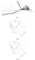
FIG. 2 is a structural schematic view of a first specific embodiment of a vehicle lamp optical system in the present disclosure; -
FIG. 3 is a structural schematic view of a translation of a first plane mirror in the vehicle lamp optical system shown inFIG. 2 ; -
FIG. 4 is a structural schematic view of a clockwise rotation of the first plane mirror in the vehicle lamp optical system shown inFIG. 2 ; -
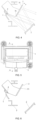
FIG. 5 is a structural schematic view of the vehicle lamp optical system shown inFIG. 2 being installed in the vehicle lamp module; -
FIG. 6 is an A-A sectional view of the vehicle lamp module shown inFIG. 5 ; -
FIG. 7 is a side view of the vehicle lamp module shown inFIG. 5 ; -
FIG. 8 is a top view of the vehicle lamp module shown inFIG. 5 ; -
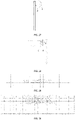
FIG. 9 is a structural schematic view of a light collimation element and a light source in the vehicle lamp optical system shown inFIG. 2 ; -
FIG. 10 is a front view of the light collimation element and the light source shown inFIG. 9 ; -
FIG. 11 is a sectional view of the light collimation element and the light source shown inFIG. 9 ; -
FIG. 12 is a light path view of the light collimation element and the light source shown inFIG. 9 ; -
FIG. 13 is a structural schematic view of a second specific embodiment of the vehicle lamp optical system in the present disclosure; -
FIG. 14 is a structural schematic view of the vehicle lamp optical system shown inFIG. 13 being installed in the vehicle lamp module; -
FIG. 15 is a B-B sectional view of the vehicle lamp module shown inFIG. 14 ; -
FIG. 16 is a top view of the vehicle lamp module shown inFIG. 14 ; -
FIG. 17 is a structural schematic view of the light collimation element and the light source in the vehicle lamp optical system shown inFIG. 13 ; -
FIG. 18 is a C-C sectional view ofFIG. 17 ; -
FIG. 19 is a side view of the light collimation element and the light source shown inFIG. 17 ; -
FIG. 20 is a light path view of the light collimation element and the light source shown inFIG. 17 ; -
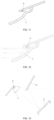
FIG. 21 is a structural schematic view of a third specific embodiment of the vehicle lamp optical system in the present disclosure; -
FIG. 22 is a structural schematic view of adjusting installation positions of the light collimation element and an alignment optical element in the vehicle lamp optical system shown inFIG. 21 ; -
FIG. 23 is a light path view before and after adjustment of the light collimation element and the alignment optical element in the vehicle lamp optical system shown inFIG. 21 ; -
FIG. 24 is a structural schematic view of a fourth specific embodiment of the vehicle lamp optical system in the present disclosure; -
FIG. 25 is a structural schematic view of the light collimation element and the light source in the vehicle lamp optical system shown inFIG. 24 ; -
FIG. 26 is a D-D sectional view ofFIG. 25 ; -
FIG. 27 is a side view of the light collimation element and the light source shown inFIG. 25 ; -
FIG. 28 is a light path view of the light collimation element and the light source shown inFIG. 25 ; -
FIG. 29 is a schematic view of a screen illumination of a low-beam illumination light shape with a light-and-dark cut-off line; and -
FIG. 30 is a schematic view of the screen illumination with a high-beam illumination light shape with a maximum value of central brightness. - The specific embodiments of the present disclosure will be described in detail below with reference to the drawings. It should be understood that the specific embodiments described herein are only used to illustrate and explain the present disclosure, and the protection scope of the present disclosure is not limited to the following specific embodiments.
- In the description of the present disclosure, it should be explained that the orientation relationships indicated by "up", "down", "front", "rear", "left", "right", etc. are only for the convenience of describing the present disclosure and simplifying the description, based on the vehicle lamp optical system, "front" refers to a direction referred by a light-emitting direction, "rear" refers to a direction opposite to "front", "left" refers to a left side in the light-emitting direction, and "right" refers to a right side in the light-emitting direction, that is, they are the same as the left and right side directions of the normal driving of the vehicle, "up" refers to an upper in the light-emitting direction, and "down" refers to a lower in the light-emitting direction. In the present disclosure, the light-emitting path of a
light collimation element 1 refers to a light path in a main transmission direction after the lights are converged by thelight collimation element 1, and the light-emitting path of the alignmentoptical element 2 refers to a light path in a main transmission direction after the light is collected and collimated by the alignmentoptical element 2, the light-emitting paths of thefirst plane mirror 31 and thesecond plane mirror 33 refer to the light paths in the main transmission directions after the lights are reflected by the plane mirrors. For those ordinarily skilled in the art, the specific meanings of the above-mentioned terms in the present disclosure can be understood according to specific situations. - In the description of the present disclosure, it should be noted that the change of the "installation position" of an element in the vehicle lamp optical system includes the translation of the element (that is, the installation angle of the element remains unchanged, but the element moves laterally, vertically or obliquely) and/ or rotation of the element (that is, the element can be rotated around a certain axis); the change of the "relative position" between two elements includes the change of the relative distance between the two elements and/or the change of the relative angle between the two elements; and the "standard position" of the illumination light shape refers to the projection position of the illumination light shape on the light-match screen stipulated in "
GB 25991-2010 - A vehicle lamp optical system provided by a first aspect of the present disclosure, referring to
FIG. 2 to FIG. 4 ,FIG. 13 , andFIG. 21 toFIG. 24 , which comprises a basic optical subsystem and alight reflecting system 3, wherein the basic optical subsystem comprises alight collimation element 1 and an alignmentoptical element 2, thelight reflecting system 3 comprises afirst plane mirror 31 located on a light-emitting path of the alignmentoptical element 2, and/or asecond plane mirror 33 located on a light-emitting path of thelight collimation element 1, wherein at least one of thelight collimation element 1, the alignmentoptical element 2, thefirst plane mirror 31, and thesecond plane mirror 33 is adjustable in an installation position, so as to change a relative position between at least two of thelight collimation element 1, the alignmentoptical element 2, thefirst plane mirror 31, and thesecond plane mirror 33, so that the emitting light of thelight collimation element 1 is subjected to light path conversion through the alignmentoptical element 2 and thelight reflecting system 3 and then is projected to form a set illumination light shape. - It should be noted that the installation position of the alignment
optical element 2 may be located on the light-emitting path of thelight collimation element 1, or may be located on the light-emitting path of a certain plane mirror (for example, the second plane mirror 33); the installation positions of thelight collimation element 1, the alignmentoptical element 2, thefirst plane mirror 31 and thesecond plane mirror 33 can be performed by driving adjustment through connecting with the driving mechanism respectively or manual adjustment; the set illumination light shape may be set according to the vehicle lamp system where the vehicle lamp optical system is located, for example, it may be a low-beam illumination light shape, or a high-beam illumination light shape of headlamp or other vehicle lamp illumination light shapes. After the set illumination light shape is determined, the installation position of at least one of thelight collimation element 1, the alignmentoptical element 2, thefirst plane mirror 31 and thesecond plane mirror 33 can be adjusted, and then the shape of light shape formed on the light-match screen is the same as the shape of set illumination light shape. - According to the vehicle lamp optical system of the above-mentioned basic technical solutions of the present disclosure, the light collimation element 1, the alignment optical element 2, the first plane mirror 31 and the second plane mirror 33 may be respectively adjustable in installation positions, or the installation position of one of them may be fixed, and the other three may be adjustable in the installation positions, or the installation positions of two of them are fixed, and the other two are adjustable in the installation positions, or the installation positions of three of them are fixed, and the remaining one is adjustable in installation position thereof, so as to adjust the relative position between at least two of the light collimation element 1, the alignment optical element 2, the first plane mirror 31 and the second plane mirror 33, thereby meeting the different modelings of vehicle lamps and adapting to different interior spaces of the vehicle lamps, and simultaneously, the collimation of the alignment optical element 2 cooperates with the reflection of the light reflecting system 3, so that the emitting light of the light collimation element 1 is still projected in an original light-emitting direction after the light path conversion and forms the set illumination light shape, so as to achieve flexible changes in the spatial structure arrangement of the light collimation element 1, the alignment optical element 2 and the light reflecting system 3, and the light collimation element 1 and/or the alignment optical element 2 have high versatility and can be used repeatedly on different vehicle lamps, thereby reducing repetitive development.
- In the present disclosure, the set illumination light shape may be a low-beam illumination light shape with a light-and-dark cut-off line as shown in
FIG. 29 , or a high-beam illumination light shape with a central brightness maximum value as shown inFIG. 30 . The basic optical subsystem may be provided with a corresponding cut-off structure or light-shielding structure, so that the emitting light of thelight collimation element 1 is subjected to light path conversion through the alignmentoptical element 2 and thelight reflecting system 3 and then is projected to form a illumination light shape, which has the desired cut-off line and other edge shapes of light shape, wherein the cut-off structure or the light-shielding structure may be provided on thelight collimation element 1 or the alignmentoptical element 2, or an element with a cut-off structure or a light-shielding structure may be separately provided in the basic optical subsystem. For example, the set illumination light shape is the low-beam illumination light shape, as shown inFIG. 2 . The light-emitting boundary 1a of thelight collimation element 1 may be provided in a shape corresponding to the light-and-dark cut-off line of the low-beam illumination light shape, so that the emitting light of thelight collimation element 1 forms a light shape with a boundary line between light and dark regions, which is subjected to light path conversion through the alignmentoptical element 2 and thelight reflecting system 3 and then is projected to form a low-beam illumination light shape as shown inFIG. 29 ; a light-shielding plate may also be provided on the light-emitting path of thelight collimation element 1, and similarly, a light-and-dark cut-off line of the low-beam illumination light shape may be formed. - In the present disclosure, the
light collimation element 1 is provided as an element capable of converging the light emitted by the corresponding light source, so that the output light is substantially parallel, preferably, referring toFIG. 9-FIG. 12 ,FIG. 17-FIG. 20 , andFIG. 25-FIG. 28 , thelight collimation element 1 is a collimator, a alignment lens or a reflective element with a paraboloid-shaped or paraboloid-like-shaped reflecting surface. Referring toFIG. 9 to FIG. 12 , when thelight collimation element 1 is a reflective element with a reflecting surface of paraboloid shape or paraboloid-like shape, the light emitted by the light source (that is, thelight source 4 in the following) corresponding to thelight collimation element 1 is reflected by the paraboloid-shaped or paraboloid-like-shaped reflecting surface of thelight collimation element 1, and then the effect of gathering light is realized; referring toFIG. 17 to FIG. 20 , thelight collimation element 1 is a collimator, the collimator is a light gathering cup structure, outer contour surface thereof is cup-shaped, the light emitted by thelight source 4 enters into the collimator, and a part of the light is directly transmitted to the light-emitting end of the collimator, a part of the light is reflected by the outer contour surface of the collimator and then transmitted to the light-emitting end of the collimator, so as to converge the light; referring toFIG. 25 to FIG. 28 , thelight collimation element 1 is a alignment lens , which may be a plano-convex lens or a double-convex lens. The light emitted by thelight source 4 enters the alignment lens, and then is refracted by the alignment lens, thereby achieving the effect of gathering light. - The alignment
optical element 2 is provided as an element capable of collecting and collimating the light incident on the alignmentoptical element 2 and then exiting the light. Preferably, the alignmentoptical element 2 is a reflecting mirror with a reflecting surface of paraboloid shape or paraboloid-like shape. - As the first specific embodiment of the present disclosure, referring to
FIG. 2 andFIG. 13 , thelight reflecting system 3 includes afirst plane mirror 31, and the alignmentoptical element 2 is located on the light-emitting path of thelight collimation element 1. At this time, the emitting light of thelight collimation element 1 is collimated and projected to thefirst plane mirror 31 through the alignmentoptical element 2, then reflected by thefirst plane mirror 31 and then projected to form a set illumination light shape. - Preferably, the relative position of the
light collimation element 1 and the alignmentoptical element 2 is fixed. At this time, the structural positions of thelight collimation element 1 and the alignmentoptical element 2 in the basic optical subsystem remain unchanged, and the basic optical subsystem can be fixedly connected with other components such as the heat sink in the vehicle lamp module to form an assembly. According to the space in the vehicle lamp, the relative position of thefirst plane mirror 31 and the basic optical subsystem is adjusted to obtain the set illumination light shape projected in the original light-emitting direction and formed. - At this time, as a preferred form of the first specific embodiment, referring to
FIG. 3 , the installation position of the basic optical subsystem is fixed, and thefirst plane mirror 31 can be translated, so that the light-emitting direction of thefirst plane mirror 31 can be unchanged. In the actual installation process, due to the interference of other components in the lamp body of vehicle lamp, the position where thefirst plane mirror 31 is located may not be installed. Thefirst plane mirror 31 can be translated in a light-emitting direction of the alignmentoptical element 2 to the position where the dotted line is located, at this time, although the relative position of thefirst plane mirror 31 and the basic optical subsystem has changed, the emitting light of thefirst plane mirror 31 still emits in parallel and forwardly in an original direction, that is, the light-emitting direction of thefirst plane mirror 31 remains unchanged, and a set illumination light shape is formed by projection, which will not affect the light shape of the vehicle lamp. Therefore, the position of thefirst plane mirror 31 can be performed by installation position adjustment according to the layout of other components in the vehicle lamp, so that the vehicle lamp optical system of the present disclosure can be applied to various modelings and different space sizes of vehicle lamps. It should be noted that, the translation direction of thefirst plane mirror 31 is not limited to the light-emitting direction of the alignmentoptical element 2, and may also be a horizontal, vertical or other oblique translation. - As another preferred form of the first specific embodiment, the
first plane mirror 31 can be rotated around any horizontal axis in a first direction, and the basic optical subsystem can be rotated around any horizontal axis in a second direction, the first direction cooperates with the second direction so that the light-emitting direction of thefirst plane mirror 31 remains unchanged. In the present disclosure, the horizontal axis refers to a horizontal axis extending in a left-right direction of the vehicle. Thefirst plane mirror 31 and the basic optical subsystem can be rotated around the same horizontal axis, or can be rotated around different horizontal axes respectively. The unchanged light-emitting direction of thefirst plane mirror 31 is achieved through the rotation cooperation of the two. Specifically, referring toFIG. 4 , during the actual installation process, the basic optical subsystem may not be able to be positioned and installed due to the interference of other components (such as the decorative ring) in the lamp body of vehicle lamp. At this time, thefirst plane mirror 31 is rotated around the horizontal axis passing throughend point 3a thereof, and thefirst plane mirror 31 is rotated clockwise around the horizontal axis to the position of the dotted line, the emitting light of thefirst plane mirror 31 is deflected downward, and then the basic optical subsystem is rotated counterclockwise around a certain horizontal axis, so that the emitting light is restored to emit forwardly and in parallel in an original light-emitting direction, and simultaneously, the basic optical subsystem can also avoid the interference of other components. The relative position of thefirst plane mirror 31 and the basic optical subsystem is changed, so that the light-emitting direction of thefirst plane mirror 31 remains unchanged and a set illumination light shape is formed by projection. - As a second specific embodiment of the present disclosure, referring to
FIG. 21 to FIG. 23 , thelight reflecting system 3 includes asecond plane mirror 33, and the alignmentoptical element 2 is located on the light-emitting path of thesecond plane mirror 33. At this time, the emitting light of thelight collimation element 1 is reflected by thesecond plane mirror 33 to the alignmentoptical element 2, and then collimated by the alignmentoptical element 2 for projecting to form a set illumination light shape. - As a preferred form of the second specific embodiment, the installation position of the
second plane mirror 33 is fixed, a reflectingregion 32 of the emitting light of thelight collimation element 1 on thesecond plane mirror 33 is located at a fixed position on thesecond plane mirror 33, the emitting light of thelight collimation element 1 and the reflected light of thesecond plane mirror 33 are symmetrical with respect to a normal of thesecond plane mirror 33 located at a corresponding reflection point in the reflectingregion 32, and the installation positions of thelight collimation element 1 and the alignmentoptical element 2 can be adjusted respectively, so that the light-emitting direction of the alignmentoptical element 2 can be unchanged. The installation positions of thelight collimation element 1 and the alignmentoptical element 2 can respectively be adjusted according to the positions of other components in the vehicle lamp and the internal space size of the vehicle lamp, and the two cooperate with each other during adjustment to change the relative positions of thelight collimation element 1 and the alignmentoptical element 2 with respect to thesecond plane mirror 33, so that the emitting light of thelight collimation element 1 can be projected to the same position of the second plane mirror 33 (that is, the reflecting region 32), and is reflected to the same position of the alignmentoptical element 2 by thesecond plane mirror 33, thereby achieving unchanged emitting direction of the light collimated by the alignmentoptical element 2. - Specifically, referring to
FIG. 22 and FIG. 23 , thelight collimation element 1 and the alignmentoptical element 2 can respectively perform a circumferential movement around the reflectingregion 32, wherein after one of thelight collimation element 1 and the alignmentoptical element 2 moves in a clockwise direction, the other moves in a counterclockwise direction. It can be understood that in the case of interference from other components in the vehicle lamp, thelight collimation element 1 can also be moved in a light-emitting direction of thelight collimation element 1, and the alignmentoptical element 2 can be moved in a light-emitting direction of thesecond plane mirror 33, so as to adjust the installation positions of the two, thereby avoiding other components. - As the third specific embodiment of the present disclosure, referring to
FIG. 24 , thelight reflecting system 3 includes afirst plane mirror 31 and asecond plane mirror 33, and the alignmentoptical element 2 is located on the light-emitting path of thesecond plane mirror 33. At this time, the emitting light of thelight collimation element 1 is reflected by thesecond plane mirror 33 to the alignmentoptical element 2, then collimated by the alignmentoptical element 2 and projected to thefirst plane mirror 31, and finally reflected by thefirst plane mirror 31 and then projected to form a set illumination light shape. - As the first preferred form of the third specific embodiment, which is the same as the preferred form of the second specific embodiment, the installation position of the
second plane mirror 33 is fixed, a reflectingregion 32 of the emitting light of thelight collimation element 1 on thesecond plane mirror 33 is located at a fixed position on thesecond plane mirror 33, the emitting light of thelight collimation element 1 and the reflected light of thesecond plane mirror 33 are symmetrical with respect to a normal of thesecond plane mirror 33 located at a corresponding reflection point in the reflectingregion 32, and the installation positions of thelight collimation element 1 and the alignmentoptical element 2 can be adjusted respectively, so that the light-emitting direction of the alignmentoptical element 2 can be unchanged. The installation positions of thelight collimation element 1 and the alignmentoptical element 2 can respectively be adjusted according to the positions of other components in the vehicle lamp and the internal space size of the vehicle lamp, and the two cooperate with each other during adjustment, so that the emitting light of thelight collimation element 1 can be projected to the same position of the second plane mirror 33 (that is, the reflecting region 32), and is reflected to the same position of the alignmentoptical element 2 by thesecond plane mirror 33, thereby achieving unchanged emitting direction of the light collimated by the alignmentoptical element 2. - As a second preferred form of the third specific embodiment, the installation positions of the basic optical subsystem and the
second plane mirror 33 are fixed, and thefirst plane mirror 31 can be translated, so that the light-emitting direction of thefirst plane mirror 31 can be unchanged. Thefirst plane mirror 31 can be translated horizontally, vertically or obliquely, so that the position of thefirst plane mirror 31 can be performed by installation position adjustment according to the layout of other components in the vehicle lamp, so that the vehicle lamp optical system of the present disclosure can be applied to various moldings, and different space sizes of vehicle lamps. - As a third preferred form of the third specific embodiment, the
first plane mirror 31 can be rotated around any horizontal axis in a first direction, and the basic optical subsystem and thesecond plane mirror 33 as a whole can be rotated around any horizontal axis in a second direction, the first direction cooperates with the second direction so that the light-emitting direction of thefirst plane mirror 31 is unchanged. The basic optical subsystem and thesecond plane mirror 33 as the whole and thefirst plane mirror 31 can be rotated around the same horizontal axis, or can be rotated around different horizontal axes respectively. The light-emitting direction of thefirst plane mirror 31 is kept unchanged through the rotation cooperation of the two. In the actual installation process, thefirst plane mirror 31, the basic optical subsystem and thesecond plane mirror 33 can respectively avoid the interference of other components (such as the decorative ring) in the lamp body of vehicle lamp. - As another preferred form of the first specific embodiment and the third specific embodiment, the
first plane mirror 31 can be rotated around any horizontal axis and/or any vertical axis, so that the set illumination light shape can be projected at a standard position. At this time, only by adjusting the angle of thefirst plane mirror 31, the light-emitting direction of the vehicle lamp optical system can be adjusted, so that the set illumination light shape formed by the projection of the emitting light of thefirst plane mirror 31 is located at the standard position specified by the regulations. The adjustment method can effectively reduce the dimming space of the vehicle lamp optical system and the weight of the component adjusted, thereby contributing to the improvement of the reliability of the vehicle lamp. - On the basis of the above-mentioned vehicle lamp optical system of the present disclosure, referring to
FIG. 5 to FIG. 8 andFIG. 14 to FIG. 16 , a second aspect of the present disclosure provides a vehicle lamp module, which comprises the above-mentioned vehicle lamp optical system and thelight source 4 provided corresponding to thelight collimation element 1. It should be noted that thelight source 4 may be an LED light source or a laser light source, and preferably, thelight source 4 is an LED light-emitting chip. The vehicle lamp module can also be provided with components, such as mountingbracket 5, or heat sink, cooperating with the vehicle lamp optical system. The above-mentioned vehicle lamp optical system can cooperate with other components in the vehicle lamp module, so as to effectively improve the flexibility of the space layout and the space utilization rate of the vehicle lamp module. - A third aspect of the present disclosure provides a vehicle, which includes the above-mentioned vehicle lamp module. Therefore, there are at least all the beneficial effects brought by the technical solutions of the above embodiments of the vehicle lamp optical system and the vehicle lamp module, which will not be repeated here.
- It can be seen from the above description that the vehicle lamp optical system of the present disclosure can adjust the relative position between at least two of the
light collimation element 1, the alignmentoptical element 2, thefirst plane mirror 31 and thesecond plane mirror 33, so that a emitting light oflight collimation element 1 is subjected to light path conversion through the alignmentoptical element 2 and thelight reflecting system 3 and then is projected to form a set illumination light shape, thereby realizing the change of the spatial structure arrangement of thelight collimation element 1, the alignmentoptical element 2 and thelight reflecting system 3, which makes the spatial layout of the vehicle lamp optical system more flexible, and effectively improves the space utilization rate in the vehicle lamp, so as to meet the different moldings of vehicle lamps and adapt to different interior spaces of vehicle lamps; thelight collimation element 1 and the alignmentoptical element 2 can be used repeatedly on different vehicle lamps (such as headlamp, fog lamp) to reduce repetitive development. More particularly, compared with the fact that in the existing vehicle lamp system, the angle adjustment of the whole vehicle lamp module is required to realize the adjustment of the light-emitting direction, in the present disclosure, only by adjusting the angle of thefirst plane mirror 31, the light-emitting direction of the vehicle lamp optical system can be adjusted so that the illumination light shape is located at the standard position, which can effectively reduce the dimming space and the weight of the components adjusted, contribute to the improvement of the reliability of the vehicle lamp, avoid the need for overall dimming when the overall fixed vehicle lamp system is dimming, and the defects of putting forward higher requirements for the support and adjustment system. - The preferred embodiments of the present disclosure have been described above in detail with reference to the drawings, however, the present disclosure is not limited thereto. Within the scope of the technical concept of the present disclosure, various simple modifications can be made to the technical solutions of the present disclosure, which includes combining various specific technical features in any suitable manner. In order to avoid unnecessary repetition, the present disclosure will not describe various possible combinations. However, these simple modifications and combinations should also be regarded as the contents disclosed in the present disclosure, and all belong to the protection scope of the present disclosure.
| 1-light collimation element; | 1a-light-emitting boundary; |
| 2-alignment optical element; | 3-light reflecting system; |
| 3a-end point; | 31-first plane mirror; |
| 32-reflecting region; | 33-second plane mirror; |
| 4-light source; | 5-mounting bracket; |
| a-reflecting mirror; | b-lens; |
| c-light shading part. |
Claims (12)
- A vehicle lamp optical system, comprising a basic optical subsystem and a light reflecting system (3), wherein the basic optical subsystem comprises a light collimation element (1) and an alignment optical element (2), the light reflecting system (3) comprises a first plane mirror (31) located on a light-emitting path of the alignment optical element (2), and/or a second plane mirror (33) located on a light-emitting path of the light collimation element (1),
wherein at least one of the light collimation element (1), the alignment optical element (2), the first plane mirror (31), and the second plane mirror (33) is adjustable in an installation position, so as to change a relative position between at least two of the light collimation element (1), the alignment optical element (2), the first plane mirror (31), and the second plane mirror (33), so that a emitting light of the light collimation element (1) is subjected to light path conversion through the alignment optical element (2) and the light reflecting system (3) and then is projected to form a set illumination light shape. - The vehicle lamp optical system according to claim 1, wherein the light reflecting system (3) comprises the first plane mirror (31), and the alignment optical element (2) is located on the light-emitting path of the light collimation element (1).
- The vehicle lamp optical system according to claim 1, wherein the light reflecting system (3) comprises the second plane mirror (33), and the alignment optical element (2) is located on a light-emitting path of the second plane mirror (33).
- The vehicle lamp optical system according to claim 1, wherein the light reflecting system (3) comprises the first plane mirror (31) and the second plane mirror (33), and the alignment optical element (2) is located on a light-emitting path of the second plane mirror (33).
- The vehicle lamp optical system according to claim 2 or 4, wherein an installation position of the basic optical subsystem or installation positions of the basic optical subsystem and the second plane mirror (33) is/are fixed, and the first plane mirror (31) can be translated, so that a light-emitting direction of the first plane mirror (31) can be unchanged.
- The vehicle lamp optical system according to claim 2 or 4, wherein the first plane mirror (31) can be rotated around any horizontal axis in a first direction, the basic optical subsystem or the basic optical subsystem and the second plane mirror (33) as a whole can be rotated around any horizontal axis in a second direction, and the first direction cooperates with the second direction so that a light-emitting direction of the first plane mirror (31) is unchanged.
- The vehicle lamp optical system according to claim 2 or 4, wherein the first plane mirror (31) can be rotated around any horizontal axis and/or any vertical axis, so that a set illumination light shape can be projected at a standard position.
- The vehicle lamp optical system according to claim 3 or 4, wherein an installation position of the second plane mirror (33) is fixed, a reflecting region (32) of an emitting light of the light collimation element (1) on the second plane mirror (33) is located at a fixed position on the second plane mirror (33), the emitting light of the light collimation element (1) and a reflected light of the second plane mirror (33) are symmetrical with respect to a normal of the second plane mirror (33) located at a corresponding reflection point in the reflecting region (32), and installation positions of the light collimation element (1) and the alignment optical element (2) can be adjusted respectively, so that a light-emitting direction of the alignment optical element (2) can be unchanged.
- The vehicle lamp optical system according to any one of claims 1 to 4, wherein the light collimation element (1) is a collimator, an alignment lens or a reflective element with a reflecting surface of paraboloid shape or paraboloid-like shape.
- The vehicle lamp optical system according to any one of claims 1 to 4, wherein the alignment optical element (2) is a reflecting mirror with a reflecting surface of paraboloid shape or paraboloid-like shape.
- A vehicle lamp module, comprising the vehicle lamp optical system according to any one of claims 1 to 10 and a light source (4) set corresponding to the light collimation element (1).
- A vehicle, comprising the vehicle lamp module according to claim 11.
Applications Claiming Priority (2)
| Application Number | Priority Date | Filing Date | Title |
|---|---|---|---|
| CN202010609464.8A CN113932189A (en) | 2020-06-29 | 2020-06-29 | Car light optical system, car light module and vehicle |
| PCT/CN2021/080536 WO2022001179A1 (en) | 2020-06-29 | 2021-03-12 | Vehicle lamp optical system, vehicle lamp module, and vehicle |
Publications (2)
| Publication Number | Publication Date |
|---|---|
| EP4137742A1 true EP4137742A1 (en) | 2023-02-22 |
| EP4137742A4 EP4137742A4 (en) | 2023-10-18 |
Family
ID=79272798
Family Applications (1)
| Application Number | Title | Priority Date | Filing Date |
|---|---|---|---|
| EP21833529.7A Pending EP4137742A4 (en) | 2020-06-29 | 2021-03-12 | Vehicle lamp optical system, vehicle lamp module, and vehicle |
Country Status (3)
| Country | Link |
|---|---|
| EP (1) | EP4137742A4 (en) |
| CN (1) | CN113932189A (en) |
| WO (1) | WO2022001179A1 (en) |
Family Cites Families (11)
| Publication number | Priority date | Publication date | Assignee | Title |
|---|---|---|---|---|
| DE3342919A1 (en) * | 1983-11-26 | 1985-06-05 | Bosch Gmbh Robert | HEADLIGHTS FOR MOTOR VEHICLES |
| JP3148575B2 (en) * | 1995-06-08 | 2001-03-19 | 本田技研工業株式会社 | Headlight device for vehicles |
| DE102004032095A1 (en) * | 2004-07-01 | 2006-02-16 | Hella Kgaa Hueck & Co. | Motor vehicle headlight has electronically movable macro mirror surface and gives a combination of both static and dynamic light distributions |
| FR2982929B1 (en) * | 2011-11-22 | 2014-01-17 | Valeo Vision | LIGHT EMITTING DEVICE FOR MOTOR VEHICLE PROJECTOR |
| TWI565605B (en) * | 2012-02-20 | 2017-01-11 | 鴻海精密工業股份有限公司 | Vehicle headlamp modulef |
| CN104676490B (en) * | 2015-02-16 | 2017-01-04 | 深圳市科曼医疗设备有限公司 | Light fixture and operating lamp |
| KR20170079355A (en) * | 2015-12-30 | 2017-07-10 | 엘지이노텍 주식회사 | Light emitting apparatus, optical module including the apparatus, and vehicle including the module |
| CN206522707U (en) * | 2016-12-30 | 2017-09-26 | 徐煜 | The Vehicle lamp structure of distance-light one |
| CN207831253U (en) * | 2018-01-16 | 2018-09-07 | 深圳市中科创激光技术有限公司 | A kind of adaptive three primary colours headlight for vehicles |
| CN210740276U (en) * | 2019-11-13 | 2020-06-12 | 华域视觉科技(上海)有限公司 | Low-beam reflection type headlamp module and vehicle |
| CN212565607U (en) * | 2020-06-29 | 2021-02-19 | 华域视觉科技(上海)有限公司 | Car light optical system, car light module and vehicle |
-
2020
- 2020-06-29 CN CN202010609464.8A patent/CN113932189A/en active Pending
-
2021
- 2021-03-12 EP EP21833529.7A patent/EP4137742A4/en active Pending
- 2021-03-12 WO PCT/CN2021/080536 patent/WO2022001179A1/en unknown
Also Published As
| Publication number | Publication date |
|---|---|
| EP4137742A4 (en) | 2023-10-18 |
| CN113932189A (en) | 2022-01-14 |
| WO2022001179A1 (en) | 2022-01-06 |
Similar Documents
| Publication | Publication Date | Title |
|---|---|---|
| US9506615B2 (en) | Motor vehicle headlamp having a multi-function projection module | |
| CN104421800B (en) | Vehicle lamp unit | |
| JP7217360B2 (en) | High and low beam integrated car lamp illumination device, car lamp and vehicle | |
| EP3982035A1 (en) | Optical component for vehicle light, and vehicle headlight | |
| US8287167B2 (en) | Lamp unit | |
| JP6516495B2 (en) | Vehicle lamp | |
| EP2664841A2 (en) | Vehcile headlamp with both low-beam and high-beam and devoid of moving parts | |
| JP2021517334A (en) | Vehicle lamp module and automobiles using it | |
| CN210740277U (en) | High-low beam integrated headlamp module, headlamp and vehicle | |
| CN210740260U (en) | Headlamp module and vehicle | |
| KR102610227B1 (en) | Headlight optical elements, headlight modules, vehicle lamps and vehicles | |
| CN212565607U (en) | Car light optical system, car light module and vehicle | |
| CN109282234B (en) | Projection unit for automobile dipped headlight and automobile lamp thereof | |
| WO2021093233A1 (en) | Reflection-type headlamp module, headlamp module, headlamp and vehicle | |
| JP2013171833A (en) | Vehicle headlamp including beam changing assembly | |
| EP3885644B1 (en) | Low-beam optical module, low-beam illumination module, vehicle lamp and vehicle | |
| CN111076141A (en) | Car light module and car light | |
| CN105402669A (en) | High beam and lower beam integrated LED headlamp | |
| TW201932750A (en) | Road-adaptive headlight | |
| CN103196087B (en) | Headlight for automobile | |
| EP4137742A1 (en) | Vehicle lamp optical system, vehicle lamp module, and vehicle | |
| JP5193546B2 (en) | Vehicle lighting | |
| CN209744279U (en) | Bifocal convex lens type high-low beam vehicle lamp without moving separation blade | |
| TWM615055U (en) | Vehicle lighting device | |
| CN207555484U (en) | A kind of reflective automotive lamp unit |
Legal Events
| Date | Code | Title | Description |
|---|---|---|---|
| STAA | Information on the status of an ep patent application or granted ep patent |
Free format text: STATUS: THE INTERNATIONAL PUBLICATION HAS BEEN MADE |
|
| PUAI | Public reference made under article 153(3) epc to a published international application that has entered the european phase |
Free format text: ORIGINAL CODE: 0009012 |
|
| STAA | Information on the status of an ep patent application or granted ep patent |
Free format text: STATUS: REQUEST FOR EXAMINATION WAS MADE |
|
| 17P | Request for examination filed |
Effective date: 20221116 |
|
| AK | Designated contracting states |
Kind code of ref document: A1 Designated state(s): AL AT BE BG CH CY CZ DE DK EE ES FI FR GB GR HR HU IE IS IT LI LT LU LV MC MK MT NL NO PL PT RO RS SE SI SK SM TR |
|
| REG | Reference to a national code |
Ref country code: DE Ref legal event code: R079 Free format text: PREVIOUS MAIN CLASS: F21S0041141000 Ipc: F21S0041365000 |
|
| STAA | Information on the status of an ep patent application or granted ep patent |
Free format text: STATUS: EXAMINATION IS IN PROGRESS |
|
| DAV | Request for validation of the european patent (deleted) | ||
| DAX | Request for extension of the european patent (deleted) | ||
| A4 | Supplementary search report drawn up and despatched |
Effective date: 20230914 |
|
| RIC1 | Information provided on ipc code assigned before grant |
Ipc: F21S 41/675 20180101ALI20230908BHEP Ipc: F21S 41/365 20180101AFI20230908BHEP |
|
| 17Q | First examination report despatched |
Effective date: 20230926 |