EP4137685A1 - Method and system for supplying fuel gas - Google Patents
Method and system for supplying fuel gas Download PDFInfo
- Publication number
- EP4137685A1 EP4137685A1 EP22186812.8A EP22186812A EP4137685A1 EP 4137685 A1 EP4137685 A1 EP 4137685A1 EP 22186812 A EP22186812 A EP 22186812A EP 4137685 A1 EP4137685 A1 EP 4137685A1
- Authority
- EP
- European Patent Office
- Prior art keywords
- fuel
- passage
- air
- compressor
- pressure
- Prior art date
- Legal status (The legal status is an assumption and is not a legal conclusion. Google has not performed a legal analysis and makes no representation as to the accuracy of the status listed.)
- Pending
Links
- 238000000034 method Methods 0.000 title claims description 23
- 239000002737 fuel gas Substances 0.000 title description 3
- 239000000446 fuel Substances 0.000 claims abstract description 169
- 238000002485 combustion reaction Methods 0.000 claims abstract description 29
- 238000004891 communication Methods 0.000 claims abstract description 6
- 239000012530 fluid Substances 0.000 claims abstract description 6
- 230000008859 change Effects 0.000 claims description 4
- 238000011144 upstream manufacturing Methods 0.000 claims description 4
- 230000000903 blocking effect Effects 0.000 claims description 2
- 230000004044 response Effects 0.000 claims description 2
- 239000007789 gas Substances 0.000 description 20
- VNWKTOKETHGBQD-UHFFFAOYSA-N methane Chemical compound C VNWKTOKETHGBQD-UHFFFAOYSA-N 0.000 description 12
- ATUOYWHBWRKTHZ-UHFFFAOYSA-N Propane Chemical compound CCC ATUOYWHBWRKTHZ-UHFFFAOYSA-N 0.000 description 4
- 239000007788 liquid Substances 0.000 description 4
- 239000003345 natural gas Substances 0.000 description 4
- 239000000203 mixture Substances 0.000 description 3
- 230000008569 process Effects 0.000 description 3
- 238000010248 power generation Methods 0.000 description 2
- 239000001294 propane Substances 0.000 description 2
- OTMSDBZUPAUEDD-UHFFFAOYSA-N Ethane Chemical compound CC OTMSDBZUPAUEDD-UHFFFAOYSA-N 0.000 description 1
- 230000009286 beneficial effect Effects 0.000 description 1
- 239000001273 butane Substances 0.000 description 1
- 239000003054 catalyst Substances 0.000 description 1
- 230000003749 cleanliness Effects 0.000 description 1
- 238000010586 diagram Methods 0.000 description 1
- 239000002283 diesel fuel Substances 0.000 description 1
- 238000003958 fumigation Methods 0.000 description 1
- 239000003502 gasoline Substances 0.000 description 1
- 238000012986 modification Methods 0.000 description 1
- 230000004048 modification Effects 0.000 description 1
- IJDNQMDRQITEOD-UHFFFAOYSA-N n-butane Chemical compound CCCC IJDNQMDRQITEOD-UHFFFAOYSA-N 0.000 description 1
- OFBQJSOFQDEBGM-UHFFFAOYSA-N n-pentane Natural products CCCCC OFBQJSOFQDEBGM-UHFFFAOYSA-N 0.000 description 1
- 230000009467 reduction Effects 0.000 description 1
Images


Classifications
-
- F—MECHANICAL ENGINEERING; LIGHTING; HEATING; WEAPONS; BLASTING
- F02—COMBUSTION ENGINES; HOT-GAS OR COMBUSTION-PRODUCT ENGINE PLANTS
- F02M—SUPPLYING COMBUSTION ENGINES IN GENERAL WITH COMBUSTIBLE MIXTURES OR CONSTITUENTS THEREOF
- F02M21/00—Apparatus for supplying engines with non-liquid fuels, e.g. gaseous fuels stored in liquid form
- F02M21/02—Apparatus for supplying engines with non-liquid fuels, e.g. gaseous fuels stored in liquid form for gaseous fuels
- F02M21/04—Gas-air mixing apparatus
- F02M21/042—Mixer comprising a plurality of bores or flow passages
-
- F—MECHANICAL ENGINEERING; LIGHTING; HEATING; WEAPONS; BLASTING
- F02—COMBUSTION ENGINES; HOT-GAS OR COMBUSTION-PRODUCT ENGINE PLANTS
- F02M—SUPPLYING COMBUSTION ENGINES IN GENERAL WITH COMBUSTIBLE MIXTURES OR CONSTITUENTS THEREOF
- F02M21/00—Apparatus for supplying engines with non-liquid fuels, e.g. gaseous fuels stored in liquid form
- F02M21/02—Apparatus for supplying engines with non-liquid fuels, e.g. gaseous fuels stored in liquid form for gaseous fuels
- F02M21/0218—Details on the gaseous fuel supply system, e.g. tanks, valves, pipes, pumps, rails, injectors or mixers
- F02M21/023—Valves; Pressure or flow regulators in the fuel supply or return system
- F02M21/0239—Pressure or flow regulators therefor
-
- F—MECHANICAL ENGINEERING; LIGHTING; HEATING; WEAPONS; BLASTING
- F02—COMBUSTION ENGINES; HOT-GAS OR COMBUSTION-PRODUCT ENGINE PLANTS
- F02B—INTERNAL-COMBUSTION PISTON ENGINES; COMBUSTION ENGINES IN GENERAL
- F02B37/00—Engines characterised by provision of pumps driven at least for part of the time by exhaust
-
- F—MECHANICAL ENGINEERING; LIGHTING; HEATING; WEAPONS; BLASTING
- F02—COMBUSTION ENGINES; HOT-GAS OR COMBUSTION-PRODUCT ENGINE PLANTS
- F02M—SUPPLYING COMBUSTION ENGINES IN GENERAL WITH COMBUSTIBLE MIXTURES OR CONSTITUENTS THEREOF
- F02M21/00—Apparatus for supplying engines with non-liquid fuels, e.g. gaseous fuels stored in liquid form
- F02M21/02—Apparatus for supplying engines with non-liquid fuels, e.g. gaseous fuels stored in liquid form for gaseous fuels
- F02M21/0203—Apparatus for supplying engines with non-liquid fuels, e.g. gaseous fuels stored in liquid form for gaseous fuels characterised by the type of gaseous fuel
- F02M21/0215—Mixtures of gaseous fuels; Natural gas; Biogas; Mine gas; Landfill gas
-
- F—MECHANICAL ENGINEERING; LIGHTING; HEATING; WEAPONS; BLASTING
- F02—COMBUSTION ENGINES; HOT-GAS OR COMBUSTION-PRODUCT ENGINE PLANTS
- F02M—SUPPLYING COMBUSTION ENGINES IN GENERAL WITH COMBUSTIBLE MIXTURES OR CONSTITUENTS THEREOF
- F02M21/00—Apparatus for supplying engines with non-liquid fuels, e.g. gaseous fuels stored in liquid form
- F02M21/02—Apparatus for supplying engines with non-liquid fuels, e.g. gaseous fuels stored in liquid form for gaseous fuels
- F02M21/0218—Details on the gaseous fuel supply system, e.g. tanks, valves, pipes, pumps, rails, injectors or mixers
-
- F—MECHANICAL ENGINEERING; LIGHTING; HEATING; WEAPONS; BLASTING
- F02—COMBUSTION ENGINES; HOT-GAS OR COMBUSTION-PRODUCT ENGINE PLANTS
- F02M—SUPPLYING COMBUSTION ENGINES IN GENERAL WITH COMBUSTIBLE MIXTURES OR CONSTITUENTS THEREOF
- F02M21/00—Apparatus for supplying engines with non-liquid fuels, e.g. gaseous fuels stored in liquid form
- F02M21/02—Apparatus for supplying engines with non-liquid fuels, e.g. gaseous fuels stored in liquid form for gaseous fuels
- F02M21/0218—Details on the gaseous fuel supply system, e.g. tanks, valves, pipes, pumps, rails, injectors or mixers
- F02M21/0221—Fuel storage reservoirs, e.g. cryogenic tanks
-
- F—MECHANICAL ENGINEERING; LIGHTING; HEATING; WEAPONS; BLASTING
- F02—COMBUSTION ENGINES; HOT-GAS OR COMBUSTION-PRODUCT ENGINE PLANTS
- F02M—SUPPLYING COMBUSTION ENGINES IN GENERAL WITH COMBUSTIBLE MIXTURES OR CONSTITUENTS THEREOF
- F02M21/00—Apparatus for supplying engines with non-liquid fuels, e.g. gaseous fuels stored in liquid form
- F02M21/02—Apparatus for supplying engines with non-liquid fuels, e.g. gaseous fuels stored in liquid form for gaseous fuels
- F02M21/0218—Details on the gaseous fuel supply system, e.g. tanks, valves, pipes, pumps, rails, injectors or mixers
- F02M21/023—Valves; Pressure or flow regulators in the fuel supply or return system
- F02M21/0233—Details of actuators therefor
-
- F—MECHANICAL ENGINEERING; LIGHTING; HEATING; WEAPONS; BLASTING
- F02—COMBUSTION ENGINES; HOT-GAS OR COMBUSTION-PRODUCT ENGINE PLANTS
- F02M—SUPPLYING COMBUSTION ENGINES IN GENERAL WITH COMBUSTIBLE MIXTURES OR CONSTITUENTS THEREOF
- F02M21/00—Apparatus for supplying engines with non-liquid fuels, e.g. gaseous fuels stored in liquid form
- F02M21/02—Apparatus for supplying engines with non-liquid fuels, e.g. gaseous fuels stored in liquid form for gaseous fuels
- F02M21/04—Gas-air mixing apparatus
- F02M21/047—Venturi mixer
-
- F—MECHANICAL ENGINEERING; LIGHTING; HEATING; WEAPONS; BLASTING
- F02—COMBUSTION ENGINES; HOT-GAS OR COMBUSTION-PRODUCT ENGINE PLANTS
- F02M—SUPPLYING COMBUSTION ENGINES IN GENERAL WITH COMBUSTIBLE MIXTURES OR CONSTITUENTS THEREOF
- F02M35/00—Combustion-air cleaners, air intakes, intake silencers, or induction systems specially adapted for, or arranged on, internal-combustion engines
- F02M35/10—Air intakes; Induction systems
- F02M35/10091—Air intakes; Induction systems characterised by details of intake ducts: shapes; connections; arrangements
- F02M35/10118—Air intakes; Induction systems characterised by details of intake ducts: shapes; connections; arrangements with variable cross-sections of intake ducts along their length; Venturis; Diffusers
-
- F—MECHANICAL ENGINEERING; LIGHTING; HEATING; WEAPONS; BLASTING
- F02—COMBUSTION ENGINES; HOT-GAS OR COMBUSTION-PRODUCT ENGINE PLANTS
- F02M—SUPPLYING COMBUSTION ENGINES IN GENERAL WITH COMBUSTIBLE MIXTURES OR CONSTITUENTS THEREOF
- F02M35/00—Combustion-air cleaners, air intakes, intake silencers, or induction systems specially adapted for, or arranged on, internal-combustion engines
- F02M35/10—Air intakes; Induction systems
- F02M35/1015—Air intakes; Induction systems characterised by the engine type
- F02M35/10157—Supercharged engines
-
- F—MECHANICAL ENGINEERING; LIGHTING; HEATING; WEAPONS; BLASTING
- F02—COMBUSTION ENGINES; HOT-GAS OR COMBUSTION-PRODUCT ENGINE PLANTS
- F02M—SUPPLYING COMBUSTION ENGINES IN GENERAL WITH COMBUSTIBLE MIXTURES OR CONSTITUENTS THEREOF
- F02M35/00—Combustion-air cleaners, air intakes, intake silencers, or induction systems specially adapted for, or arranged on, internal-combustion engines
- F02M35/10—Air intakes; Induction systems
- F02M35/10209—Fluid connections to the air intake system; their arrangement of pipes, valves or the like
- F02M35/10229—Fluid connections to the air intake system; their arrangement of pipes, valves or the like the intake system acting as a vacuum or overpressure source for auxiliary devices, e.g. brake systems; Vacuum chambers
-
- Y—GENERAL TAGGING OF NEW TECHNOLOGICAL DEVELOPMENTS; GENERAL TAGGING OF CROSS-SECTIONAL TECHNOLOGIES SPANNING OVER SEVERAL SECTIONS OF THE IPC; TECHNICAL SUBJECTS COVERED BY FORMER USPC CROSS-REFERENCE ART COLLECTIONS [XRACs] AND DIGESTS
- Y02—TECHNOLOGIES OR APPLICATIONS FOR MITIGATION OR ADAPTATION AGAINST CLIMATE CHANGE
- Y02T—CLIMATE CHANGE MITIGATION TECHNOLOGIES RELATED TO TRANSPORTATION
- Y02T10/00—Road transport of goods or passengers
- Y02T10/10—Internal combustion engine [ICE] based vehicles
- Y02T10/30—Use of alternative fuels, e.g. biofuels
Definitions
- the present disclosure relates generally to internal combustion engines, and more particularly, to methods and systems for fuel supply in internal combustion engines.
- Internal combustion engines are employed in many applications including, for example, vehicles, mobile machines, and stationary machines such as power generation systems. While most conventional engines are designed for use with gasoline and diesel fuels, recent engine systems are suitable for combustion of alternative fuels including gaseous fuels. Gaseous fuels, such as natural gas, offer advantages such as abundance, efficiency, and cleanliness when compared to conventional fuels for internal combustion engines.
- gaseous fuel When used in an internal combustion engine, gaseous fuel can be mixed with intake air, for example in a delivery system, before the fuel is delivered to the engine for combustion.
- Some engine systems introduce gaseous fuel via fumigation, in which fuel gas is drawn into this delivery system to supply the gaseous fuel, together with air, to the engine.
- Devices for supplying gaseous fuel can include venturi sections or carburetor sections that reduce the pressure of air at the location where the gaseous fuel is introduced. While venturi sections are effective in reducing the pressure at specific locations to facilitate the supply of fuel gas under some operating conditions, they may introduce undesired performance at high air flow rates, for example. In particular, venturi sections may introduce excessive pressure loss at high-flow conditions, such as when the engine is operating at a relatively high load.
- a system for introducing a gaseous fuel to an internal combustion engine may include a fuel storage device, a compressor, and an air and fuel conduit in fluid communication with the fuel storage device and with the compressor.
- the air and fuel conduit may include a first passage and a second passage that includes a first portion and a second portion, the second portion being a venturi portion, the second passage being fluidly connected to the compressor in parallel with the first passage.
- a fuel system may include a fuel storage device and a first passage.
- the first passage may include a first air inlet configured to receive intake air, a first fuel inlet in fluid communication with the fuel storage device and configured to receive gaseous fuel downstream of the first air inlet, and a valve configured to open and close the first passage.
- the system may also include a second passage connected in parallel with the first passage, the second passage including a second air inlet configured to receive intake air and a second fuel inlet configured to receive gaseous fuel downstream of the second air inlet.
- a method for supplying fuel and air to an internal combustion engine may include controlling a flow of intake air and fuel through a first passage of an air and fuel conduit and receiving intake air and fuel with a second passage of the air and fuel conduit, the second passage being connected in parallel with the first passage.
- the method may also include opening in the first passage to permit a flow of the intake air and fuel and supplying the intake air and fuel from the first passage and from the second passage to the internal combustion engine.
- FIG. 1 illustrates an exemplary internal combustion engine system 10 according to aspects of the present disclosure.
- Internal combustion engine system 10 may include an air and fuel supply system 12 and an internal combustion engine 14 which receives air and gaseous fuel introduced with supply system 12.
- Engine 14 may include a plurality of cylinders 16 for the combustion of fuel.
- Engine 14 may be configured to combust gaseous fuel, either alone (e.g., via spark-ignition initiated with a spark plug) or together with liquid fuel, such as diesel (e.g., by compression-ignition of liquid fuel to initiate combustion).
- the gaseous fuel may include natural gas (e.g., a mixture of methane and one or more of ethane, butane, and propane), propane gas, methane gas, a biogas, a mixture thereof, or any other suitable fuel that can be supplied to intake manifold 36 and cylinders 16 in gaseous form.
- natural gas e.g., a mixture of methane and one or more of ethane, butane, and propane
- propane gas methane gas
- a biogas a mixture thereof
- Air and fuel supply system 12 may include components that connect an air inlet 18 with an intake manifold 36 to supply air, together with fuel from a fuel storage device such as fuel source 26, to cylinders 16.
- Air and fuel supply system 12 may include clean air inlet 18, a low pressure inlet air passage 20, an air and fuel conduit 22, a mixing passage or connection passage 24, a turbocharger 30, and an intake manifold 36.
- Air and fuel supply system 12 may also include components for the storage and supply of gaseous fuel.
- air and fuel supply system 12 may include the fuel source 26 and one or more fuel supply lines 28.
- Fuel source 26 may include one or more storage devices, such as fuel storage tanks, configured to store natural gas or another gaseous fuel.
- gaseous fuel may include, in addition to fuel stored in gaseous form in fuel source 26, fuel stored in a liquid form in fuel source 26 and supplied, in gaseous form, via air and fuel supply system 12.
- Air inlet 18 may allow clean intake air to enter air and fuel supply system 12 and may include one or more air filters, for example.
- Low pressure inlet air passage 20 may be connected to air inlet 18 upstream of a compressor 32 of turbocharger 30.
- An air and fuel conduit 22, also referred to herein as conduit 22, may be connected between air inlet 18 and compressor 32.
- Conduit 22 may include an inlet end connected to inlet air passage 20 and an outlet end connected to a connection passage 24.
- Conduit 22 may further include fuel inlet openings that are connected to a fuel source 26 via one or more fuel supply lines 28, as described below.
- the outlet end of conduit 22 may be connected to a compressor 32 of turbocharger 30 via connection passage 24.
- conduit 22 may be directly connected to an inlet of compressor 32, instead of being connected to compressor 32 via connection passage 24, if desired.
- turbocharger 30 is shown in FIG. 1 with both a compressor 32 and a turbine 34, system 10 may include only a compressor 32 without turbine 34, such as a compressor 32 driven by a crankshaft of engine 14.
- An outlet of compressor 32 may be connected to cylinders 16 of engine 14 via an intake manifold 36. Downstream of cylinders 16, an exhaust manifold 38 may be connected to an inlet of turbine 34 by a high pressure exhaust passage 40. An outlet of turbine 34 may be connected to a low pressure exhaust passage 42. Low pressure exhaust passage 42 may include one or more aftertreatment systems, such as catalysts, filters, etc. (not shown). Exhaust may exit system 10 through an exhaust outlet 44 downstream of passage 42 after passing through any aftertreatment systems of system 10.
- FIG. 2 is a cross-sectional view of conduit 22, connection passage 24, and compressor 32, according to an exemplary configuration of system 10.
- conduit 22 may include a plurality of parallel passages.
- passages that are "parallel" to each other provide separate or divided paths for air and/or fuel.
- conduit 22 may include a permanently-open venturi passage 52 configured to receive air 46 and fuel 48, and a selectively-opened bypass passage 54.
- Bypass passage 54 may be configured to receive air 46 at an inlet opening at the upstream end of passage 54, and configured to receive fuel 48 at fuel inlet opening 63, passage 54 being connected parallel to passage 52.
- Connection passage 24 may provide a bridge for air 46 and fuel 48 to mix and flow from conduit 22 to an inlet 66 of compressor 32.
- Compressor 32 may include compressor inlet 66, a compressor wheel 68, and an outlet 70.
- Venturi passage 52 of conduit 22 may have an approximately hourglass-shaped internal geometry that receives air at an inlet end and guides this air to an outlet end at connection passage 24 or at inlet 66.
- Venturi passage 52 may include a first widened portion 56 having an approximately constant diameter, widened portion 56 extending from an inlet end of venturi passage 52. This inlet end of widened portion 56 may receive intake air 46.
- a venturi portion or narrowed portion 58 may extend downstream of widened portion 56.
- One or more fuel inlet openings 62 may be positioned within narrowed portion 58. In an exemplary configuration, fuel inlet opening 62 may be formed in a wall of narrowed portion 58 at a narrowest diameter of the entire venturi passage 52.
- a second widened portion 60 may extend downstream from narrowed portion 58 to the outlet end of conduit 22. While portion 58 as well as passage 52 as a whole are each shown having asymmetrical shapes when upstream and downstream portions are compared to each other, passage 52 may instead be formed with an internal shape where narrowed portion 58 and/or an entirety of passage 52 is symmetrical, having a plane of symmetric that extends orthogonal to the flow path of air.
- bypass passage 54 may extend from the inlet end of conduit 22 to the outlet end of conduit 22.
- bypass passage 54 has a substantially constant diameter through the entire length of passage 54, including an air inlet formed at the inlet end of conduit 22.
- Bypass passage 54 may also include one or more fuel inlet openings 62, like venturi passage 52.
- Bypass passage 54 may house a bypass passage valve 64 configured to be opened and closed to respectively permit and prohibit a flow of air 46 and gaseous fuel 48. Valve 64 may be opened and closed by an actuator 72.
- bypass valve 64 may be positioned downstream of the inlet of passage 54 and of fuel inlet opening 62.
- Bypass valve 64 may include a valve member, such as a butterfly valve member, that is configured to gradually open to control an amount of restriction to flow through passage 54.
- actuator 72 may actuate bypass valve 64 between a plurality of positions between a fully closed position, in which no flow of either air or fuel is permitted through bypass passage 54, and a fully opened position in which flow of both air and gaseous fuel is fully unrestricted through passage 54.
- Bypass valve 64 may be a pneumatically-actuated valve that is activated by actuator 72 at a predetermined threshold pressure. For example, bypass valve 64 may begin to open at a predetermined opening pressure, and may gradually open until reaching a predetermined maximum pressure at which valve 64 is fully opened.
- the predetermined opening pressure and predetermined maximum pressure may correspond to different pressures of gas that has been compressed with compressor wheel 68 of compressor 32 and output from compressor 32. In particular, these pressures may correspond to a pressure of gas output from compressor 32 via compressor outlet 70.
- pressure line 74 may be in fluid communication with actuator 72 and with compressor outlet 70.
- the pressure of gas within line 74 which corresponds to the pressure of gas of compressor outlet 70, may act against a spring of actuator 72 that biases valve 64 to a closed position.
- the pressure of gas corresponding to the predetermined opening pressure may be the minimum pressure sufficient to overcome the biasing force of this spring.
- valve 64 may be configured to gradually open between a predetermined opening pressure and a predetermined maximum pressure so as to provide varying amounts of restriction through bypass passage 54
- valve 64 and actuator 72 may instead be configured to fully open valve 64 immediately when the pressure of gas output from compressor 32 reaches the predetermined opening pressure, for example by selecting an appropriate spring member for actuator 72.
- a controller for controlling the position of valve 64 may cause actuator 72 to fully open valve 64 when the pressure of gas in compressor outlet 70 reaches the predetermined opening pressure. Electrically-actuated configurations of valve 64 may also enable gradual opening of valve 64 between the predetermined opening pressure and the predetermined maximum pressure.
- a plurality of fuel inlet openings 62 may be formed within venturi passage 52, bypass passage 54, or both. When a plurality of fuel inlet openings 62 are provided, these passages may be circumferentially spaced apart from each other, longitudinally spaced apart from each other, or both.
- system 10 may be employed in a variety of internal combustion engines that are configured to combust gaseous fuel, either alone or together with another fuel source, such as a liquid fuel (e.g., diesel).
- exemplary applications for system 10, including engine 14, may include power generation systems, machines (e.g., dozers, excavators, loaders, pipelaying machines, grading machines, etc.), vehicles, and others.
- System 10 may be applied, for example, in engine systems that are configured for combustion of gaseous fuel and air, and in particular, engine systems including a compressor that compress gaseous fuel and air before supplying mixed fuel and air to the cylinders of the engine.
- gaseous fuel and air may be supplied to engine 14 by air and fuel supply system 12.
- Clean air from outside system 10 may enter air and fuel supply system 12 via air inlet 18. This air may be guided to an inlet end of conduit 22 by low pressure inlet air passage 20.
- Fuel may also enter at least one passage of conduit 22 from fuel source 26 and one or more fuel supply lines 28. The air and fuel may mix together before the fuel and air are supplied to compressor 32.
- Compressor 32 may receive air and gaseous fuel from conduit 22, compress this air and fuel via compressor wheel 68 ( FIG. 2 ), and supply the compressed air and fuel, via compressor outlet 70, to intake manifold 36.
- the mixed air and fuel may be received within cylinders 16 (e.g., via one or more respective intake valves of each cylinder 16, not shown) and combusted.
- the exhaust produced by this combustion may be supplied to exhaust manifold 38 (e.g., via one or more respective exhaust valves of each cylinder 16, not shown). Exhaust may then be supplied to high pressure exhaust passage 40, enter an inlet of turbine 34, and exit system 10 via low pressure exhaust passage 42 and exhaust outlet 44.
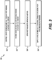
- FIG. 3 is a flowchart illustrating an exemplary method 300 for supplying fuel and air to an internal combustion engine, according to aspects of the present disclosure.
- Method 300 may include receiving air and gaseous fuel, such as natural gas, with a plurality of parallel passages (e.g., first and second passages) before the air and fuel are supplied to internal combustion engine 14.
- These passages which may include venturi passage 52 and bypass passage 54, may be connected in parallel and configured to allow the flow of air and fuel to engine 14 to change depending on the intake air and fuel requirements of engine 14.
- venturi passage 52 may be configured as a low-pressure passage that supplies air and fuel to engine 14 when the flow of air through passage 52 is relatively low (e.g., during a low-load condition of engine 14).
- Bypass passage 54 may be configured as a high-pressure passage that is closed (e.g., by valve 64) when engine 14 is in a low-load condition, and open when engine 14 is in a high-load condition.
- a flow of intake air and fuel may be controlled within air and fuel supply system 12 ( Fig. 1 ), and in particular, within bypass passage 54.
- the flow of this air and fuel may be controlled with, for example, valve 64 within bypass passage 54.
- valve 64 may fully close bypass passage 54.
- valve 64 may prohibit the flow of received intake air 46 through bypass passage 54, allowing an entirety of air 46 received by conduit 22 to pass through narrowed portion 58 to draw a desired quantity of fuel from opening 62, facilitating low-load operation of engine 14.
- a step 304 intake air 46 and gaseous fuel 48 may be received by venturi passage 52, via fuel inlet openings 62, to draw air 46 and fuel 48 into cylinders 16 of engine 14.
- valve 64 may fully close bypass passage 54, blocking the flow of fuel 48, in addition to the flow of air 46, through bypass passage 54.
- passage of air 46 and fuel 48 through passage 54 may be blocked such that an entirety of the air 46 and fuel 48 received by engine 14 is supplied via venturi passage 52, as valve 64 prevents air 46 from flowing through passage 54 to draw fuel 48 through the fuel inlet openings 62 in passage 54.
- a desired quantity of gaseous fuel may be supplied to engine 14 by venturi passage 52.
- a step 306 may be performed when the pressure of gas output with compressor outlet 70 reaches or exceeds the predetermined opening pressure following a period of time when the pressure of gas from outlet 70 was below this predetermined opening pressure.
- valve 64 of conduit 22 may open, permitting a flow of intake air and fuel received by bypass passage 54 to engine 14. This may facilitate supply of air 46 and fuel 48 to compressor 24 at a higher pressure as compared to the supply of air 46 and fuel 48 when valve 64 is closed, facilitating operation at relatively high load and/or high engine speeds.
- Valve 64 may be actuated from a closed position to an at least partially open position by actuator 72, e.g., a pneumatic actuator as illustrated in FIG. 2 and as described above.
- pressure line 74 is in fluid communication with gas output from compressor 32.
- pressure line 74 may be connected to compressor outlet 70 such that, when the pressure in compressor outlet 70 reaches the predetermined opening pressure, the pressure of air compressed by compressor wheel 68 may act against a spring member of actuator 72, moving valve 64 from the fully-closed position.
- Actuator 72 may be configured to gradually open valve 64 when the pressure of gas reaches the predetermined opening pressure.
- actuator 72 may be configured to fully open when the pressure reaches a predetermined maximum pressure, which is larger than the predetermined threshold opening at which valve 64 begins to open.
- the flow of air 46 and fuel 48 through passage 54 may gradually increase according to a corresponding increase in the speed or output (e.g., torque) of engine 14.
- actuator 72 may instead be configured to fully open valve 64 when the pressure of gas output from compressor 32 reaches the predetermined threshold pressure.
- Step 308 may include supplying intake air 46 and fuel 48 to internal combustion engine 14.
- the intake air 46 and gaseous fuel 48 received by passages 52 and 54 may exit conduit 22 and enter compressor 32, either directly (not shown) or through connection passage 24.
- air and fuel may enter intake manifold 36, where the compressed air and fuel is routed to cylinders 16 of engine 14. This fuel may be combusted in cylinders 16, creating exhaust gas that exits system 10, as described above.
- a bypass passage 54 may facilitate the supply of sufficient quantities of air and fuel under varying engine conditions, and in particular, under conditions where a higher air flow rate is desirable.
- a bypass passage 54 may be configured to receive air and gaseous fuel when relatively high airflow is desired.
- a bypass passage 54 may provide a path having reduced restriction, as compared to a venturi passage 52, to the flow of air during such high flow-rate conditions, allowing air and fuel to be supplied to an inlet of a compressor 32 at a suitable pressure.
- a bypass passage 54 may be closed under some conditions, such as low-load conditions where desired flow of air is relatively low.
- the system may be configured to draw in a sufficient quantity of fuel for expected conditions of an engine system, including both low-load conditions and high-load conditions.
- the disclosed method and system may further facilitate a reduction in compressor rotation for a particular engine condition, reducing demands on the engine system.
Landscapes
- Engineering & Computer Science (AREA)
- Chemical & Material Sciences (AREA)
- Combustion & Propulsion (AREA)
- Mechanical Engineering (AREA)
- General Engineering & Computer Science (AREA)
- Chemical Kinetics & Catalysis (AREA)
- General Chemical & Material Sciences (AREA)
- Oil, Petroleum & Natural Gas (AREA)
- Analytical Chemistry (AREA)
- Output Control And Ontrol Of Special Type Engine (AREA)
Abstract
Description
- The present disclosure relates generally to internal combustion engines, and more particularly, to methods and systems for fuel supply in internal combustion engines.
- Internal combustion engines are employed in many applications including, for example, vehicles, mobile machines, and stationary machines such as power generation systems. While most conventional engines are designed for use with gasoline and diesel fuels, recent engine systems are suitable for combustion of alternative fuels including gaseous fuels. Gaseous fuels, such as natural gas, offer advantages such as abundance, efficiency, and cleanliness when compared to conventional fuels for internal combustion engines.
- When used in an internal combustion engine, gaseous fuel can be mixed with intake air, for example in a delivery system, before the fuel is delivered to the engine for combustion. Some engine systems introduce gaseous fuel via fumigation, in which fuel gas is drawn into this delivery system to supply the gaseous fuel, together with air, to the engine. Devices for supplying gaseous fuel can include venturi sections or carburetor sections that reduce the pressure of air at the location where the gaseous fuel is introduced. While venturi sections are effective in reducing the pressure at specific locations to facilitate the supply of fuel gas under some operating conditions, they may introduce undesired performance at high air flow rates, for example. In particular, venturi sections may introduce excessive pressure loss at high-flow conditions, such as when the engine is operating at a relatively high load.
- An exemplary gas regulator and method for a multi-fuel engine is disclosed in
U.S. Patent Application Publication No. 2016/0153371 A1 ("the '371 publication") to Xinyu Ge. The gas regulator described in the '371 application regulates pressure of fuel supplied from a fuel source to a carburetor. While the gas regulator and method described in the '371 publication may supply fuel appropriately under various conditions, it may be beneficial to include an air and fuel supply passage having a plurality of individual paths to improve the supply of air and fuel to an internal combustion engine. - The disclosed methods and systems may solve one or more of the problems set forth above and/or other problems in the art. The scope of the current disclosure, however, is defined by the claims, and not by the ability to solve any specific problem.
- In one aspect, a system for introducing a gaseous fuel to an internal combustion engine may include a fuel storage device, a compressor, and an air and fuel conduit in fluid communication with the fuel storage device and with the compressor. The air and fuel conduit may include a first passage and a second passage that includes a first portion and a second portion, the second portion being a venturi portion, the second passage being fluidly connected to the compressor in parallel with the first passage.
- In another aspect, a fuel system may include a fuel storage device and a first passage. The first passage may include a first air inlet configured to receive intake air, a first fuel inlet in fluid communication with the fuel storage device and configured to receive gaseous fuel downstream of the first air inlet, and a valve configured to open and close the first passage. The system may also include a second passage connected in parallel with the first passage, the second passage including a second air inlet configured to receive intake air and a second fuel inlet configured to receive gaseous fuel downstream of the second air inlet.
- In yet another aspect, a method for supplying fuel and air to an internal combustion engine may include controlling a flow of intake air and fuel through a first passage of an air and fuel conduit and receiving intake air and fuel with a second passage of the air and fuel conduit, the second passage being connected in parallel with the first passage. The method may also include opening in the first passage to permit a flow of the intake air and fuel and supplying the intake air and fuel from the first passage and from the second passage to the internal combustion engine.
- The accompanying drawings, which are incorporated in and constitute a part of this specification, illustrate various exemplary embodiments and together with the description, serve to explain the principles of the disclosed embodiments.
-
FIG. 1 is a diagram of an internal combustion engine system including an air and fuel conduit, according to aspects of the present disclosure. -
FIG. 2 is a cross-sectional view of components of the internal combustion engine system shown inFIG. 1 , including an exemplary air and fuel conduit. -
FIG. 3 is a flowchart of an exemplary process for supplying fuel and air to an internal combustion engine, according to aspects of the present disclosure. - Both the foregoing general description and the following detailed description are exemplary and explanatory only and are not restrictive of the features, as claimed. As used herein, the terms "comprises," "comprising," "having," including," or other variations thereof, are intended to cover a non-exclusive inclusion such that a process, method, article, or apparatus that comprises a list of elements does not include only those elements, but may include other elements not expressly listed or inherent to such a process, method, article, or apparatus. Moreover, in this disclosure, relative terms, such as, for example, "about," "substantially," "generally," and "approximately" are used to indicate a possible variation of ±10% in the stated value.
-
FIG. 1 illustrates an exemplary internalcombustion engine system 10 according to aspects of the present disclosure. Internalcombustion engine system 10 may include an air andfuel supply system 12 and aninternal combustion engine 14 which receives air and gaseous fuel introduced withsupply system 12.Engine 14 may include a plurality ofcylinders 16 for the combustion of fuel.Engine 14 may be configured to combust gaseous fuel, either alone (e.g., via spark-ignition initiated with a spark plug) or together with liquid fuel, such as diesel (e.g., by compression-ignition of liquid fuel to initiate combustion). The gaseous fuel may include natural gas (e.g., a mixture of methane and one or more of ethane, butane, and propane), propane gas, methane gas, a biogas, a mixture thereof, or any other suitable fuel that can be supplied to intakemanifold 36 andcylinders 16 in gaseous form. - Air and
fuel supply system 12 may include components that connect anair inlet 18 with anintake manifold 36 to supply air, together with fuel from a fuel storage device such asfuel source 26, tocylinders 16. Air andfuel supply system 12 may includeclean air inlet 18, a low pressureinlet air passage 20, an air andfuel conduit 22, a mixing passage orconnection passage 24, aturbocharger 30, and anintake manifold 36. Air andfuel supply system 12 may also include components for the storage and supply of gaseous fuel. For example, air andfuel supply system 12 may include thefuel source 26 and one or morefuel supply lines 28.Fuel source 26 may include one or more storage devices, such as fuel storage tanks, configured to store natural gas or another gaseous fuel. As used herein, "gaseous fuel" may include, in addition to fuel stored in gaseous form infuel source 26, fuel stored in a liquid form infuel source 26 and supplied, in gaseous form, via air andfuel supply system 12. -
Air inlet 18 may allow clean intake air to enter air andfuel supply system 12 and may include one or more air filters, for example. Low pressureinlet air passage 20 may be connected toair inlet 18 upstream of acompressor 32 ofturbocharger 30. An air andfuel conduit 22, also referred to herein asconduit 22, may be connected betweenair inlet 18 andcompressor 32.Conduit 22 may include an inlet end connected toinlet air passage 20 and an outlet end connected to aconnection passage 24.Conduit 22 may further include fuel inlet openings that are connected to afuel source 26 via one or morefuel supply lines 28, as described below. The outlet end ofconduit 22 may be connected to acompressor 32 ofturbocharger 30 viaconnection passage 24. However, the outlet end ofconduit 22 may be directly connected to an inlet ofcompressor 32, instead of being connected tocompressor 32 viaconnection passage 24, if desired. Whileturbocharger 30 is shown inFIG. 1 with both acompressor 32 and aturbine 34,system 10 may include only acompressor 32 withoutturbine 34, such as acompressor 32 driven by a crankshaft ofengine 14. - An outlet of
compressor 32 may be connected tocylinders 16 ofengine 14 via anintake manifold 36. Downstream ofcylinders 16, anexhaust manifold 38 may be connected to an inlet ofturbine 34 by a highpressure exhaust passage 40. An outlet ofturbine 34 may be connected to a lowpressure exhaust passage 42. Lowpressure exhaust passage 42 may include one or more aftertreatment systems, such as catalysts, filters, etc. (not shown). Exhaust may exitsystem 10 through anexhaust outlet 44 downstream ofpassage 42 after passing through any aftertreatment systems ofsystem 10. -
FIG. 2 is a cross-sectional view ofconduit 22,connection passage 24, andcompressor 32, according to an exemplary configuration ofsystem 10. As shown inFIG. 2 ,conduit 22 may include a plurality of parallel passages. As used herein passages that are "parallel" to each other provide separate or divided paths for air and/or fuel. For example,conduit 22 may include a permanently-open venturi passage 52 configured to receiveair 46 andfuel 48, and a selectively-openedbypass passage 54.Bypass passage 54 may be configured to receiveair 46 at an inlet opening at the upstream end ofpassage 54, and configured to receivefuel 48 at fuel inlet opening 63,passage 54 being connected parallel topassage 52.Connection passage 24 may provide a bridge forair 46 andfuel 48 to mix and flow fromconduit 22 to aninlet 66 ofcompressor 32.Compressor 32 may includecompressor inlet 66, a compressor wheel 68, and anoutlet 70. - Venturi
passage 52 ofconduit 22 may have an approximately hourglass-shaped internal geometry that receives air at an inlet end and guides this air to an outlet end atconnection passage 24 or atinlet 66.Venturi passage 52 may include a first widenedportion 56 having an approximately constant diameter, widenedportion 56 extending from an inlet end ofventuri passage 52. This inlet end of widenedportion 56 may receiveintake air 46. A venturi portion or narrowedportion 58 may extend downstream of widenedportion 56. One or morefuel inlet openings 62 may be positioned within narrowedportion 58. In an exemplary configuration, fuel inlet opening 62 may be formed in a wall of narrowedportion 58 at a narrowest diameter of theentire venturi passage 52. A second widenedportion 60 may extend downstream from narrowedportion 58 to the outlet end ofconduit 22. Whileportion 58 as well aspassage 52 as a whole are each shown having asymmetrical shapes when upstream and downstream portions are compared to each other,passage 52 may instead be formed with an internal shape where narrowedportion 58 and/or an entirety ofpassage 52 is symmetrical, having a plane of symmetric that extends orthogonal to the flow path of air. -
Bypass passage 54 may extend from the inlet end ofconduit 22 to the outlet end ofconduit 22. In the exemplary configuration shown inFIG. 2 ,bypass passage 54 has a substantially constant diameter through the entire length ofpassage 54, including an air inlet formed at the inlet end ofconduit 22.Bypass passage 54 may also include one or morefuel inlet openings 62, likeventuri passage 52.Bypass passage 54 may house abypass passage valve 64 configured to be opened and closed to respectively permit and prohibit a flow ofair 46 andgaseous fuel 48.Valve 64 may be opened and closed by an actuator 72. In an exemplary configuration,bypass valve 64 may be positioned downstream of the inlet ofpassage 54 and offuel inlet opening 62.Bypass valve 64 may include a valve member, such as a butterfly valve member, that is configured to gradually open to control an amount of restriction to flow throughpassage 54. Thus, actuator 72 may actuatebypass valve 64 between a plurality of positions between a fully closed position, in which no flow of either air or fuel is permitted throughbypass passage 54, and a fully opened position in which flow of both air and gaseous fuel is fully unrestricted throughpassage 54. -
Bypass valve 64 may be a pneumatically-actuated valve that is activated by actuator 72 at a predetermined threshold pressure. For example,bypass valve 64 may begin to open at a predetermined opening pressure, and may gradually open until reaching a predetermined maximum pressure at whichvalve 64 is fully opened. The predetermined opening pressure and predetermined maximum pressure may correspond to different pressures of gas that has been compressed with compressor wheel 68 ofcompressor 32 and output fromcompressor 32. In particular, these pressures may correspond to a pressure of gas output fromcompressor 32 viacompressor outlet 70. To facilitate the actuation of actuator 72 according to the pressure of gas output fromcompressor 32,pressure line 74 may be in fluid communication with actuator 72 and withcompressor outlet 70. The pressure of gas withinline 74, which corresponds to the pressure of gas ofcompressor outlet 70, may act against a spring of actuator 72 thatbiases valve 64 to a closed position. In this example, the pressure of gas corresponding to the predetermined opening pressure may be the minimum pressure sufficient to overcome the biasing force of this spring. - While
valve 64 may be configured to gradually open between a predetermined opening pressure and a predetermined maximum pressure so as to provide varying amounts of restriction throughbypass passage 54,valve 64 and actuator 72 may instead be configured to fullyopen valve 64 immediately when the pressure of gas output fromcompressor 32 reaches the predetermined opening pressure, for example by selecting an appropriate spring member for actuator 72. As another example where actuator 72 is electrically actuated, a controller for controlling the position ofvalve 64 may cause actuator 72 to fullyopen valve 64 when the pressure of gas incompressor outlet 70 reaches the predetermined opening pressure. Electrically-actuated configurations ofvalve 64 may also enable gradual opening ofvalve 64 between the predetermined opening pressure and the predetermined maximum pressure. - While one fuel inlet opening 62 is shown for
passage 52 and another fuel inlet opening 62 is shown forpassage 54, a plurality offuel inlet openings 62 may be formed withinventuri passage 52,bypass passage 54, or both. When a plurality offuel inlet openings 62 are provided, these passages may be circumferentially spaced apart from each other, longitudinally spaced apart from each other, or both. - The disclosed aspects of
system 10 may be employed in a variety of internal combustion engines that are configured to combust gaseous fuel, either alone or together with another fuel source, such as a liquid fuel (e.g., diesel). Exemplary applications forsystem 10, includingengine 14, may include power generation systems, machines (e.g., dozers, excavators, loaders, pipelaying machines, grading machines, etc.), vehicles, and others.System 10 may be applied, for example, in engine systems that are configured for combustion of gaseous fuel and air, and in particular, engine systems including a compressor that compress gaseous fuel and air before supplying mixed fuel and air to the cylinders of the engine. - During the operation of
system 10,engine 14 combusts gaseous fuel and air supplied tocylinders 16 to generate power. As shown inFIG. 1 , gaseous fuel and air may be supplied toengine 14 by air andfuel supply system 12. Clean air fromoutside system 10 may enter air andfuel supply system 12 viaair inlet 18. This air may be guided to an inlet end ofconduit 22 by low pressureinlet air passage 20. Fuel may also enter at least one passage ofconduit 22 fromfuel source 26 and one or morefuel supply lines 28. The air and fuel may mix together before the fuel and air are supplied tocompressor 32.Compressor 32 may receive air and gaseous fuel fromconduit 22, compress this air and fuel via compressor wheel 68 (FIG. 2 ), and supply the compressed air and fuel, viacompressor outlet 70, tointake manifold 36. The mixed air and fuel may be received within cylinders 16 (e.g., via one or more respective intake valves of eachcylinder 16, not shown) and combusted. The exhaust produced by this combustion may be supplied to exhaust manifold 38 (e.g., via one or more respective exhaust valves of eachcylinder 16, not shown). Exhaust may then be supplied to highpressure exhaust passage 40, enter an inlet ofturbine 34, andexit system 10 via lowpressure exhaust passage 42 andexhaust outlet 44. -
FIG. 3 is a flowchart illustrating anexemplary method 300 for supplying fuel and air to an internal combustion engine, according to aspects of the present disclosure.Method 300 may include receiving air and gaseous fuel, such as natural gas, with a plurality of parallel passages (e.g., first and second passages) before the air and fuel are supplied tointernal combustion engine 14. These passages, which may includeventuri passage 52 andbypass passage 54, may be connected in parallel and configured to allow the flow of air and fuel toengine 14 to change depending on the intake air and fuel requirements ofengine 14. For example,venturi passage 52 may be configured as a low-pressure passage that supplies air and fuel toengine 14 when the flow of air throughpassage 52 is relatively low (e.g., during a low-load condition of engine 14). During this low-load operation ofengine 14, the constriction formed within narrowedportion 58 may causeair 46 to drawfuel 48 out from fuel inlet opening 62 ofpassage 52.Bypass passage 54 may be configured as a high-pressure passage that is closed (e.g., by valve 64) whenengine 14 is in a low-load condition, and open whenengine 14 is in a high-load condition. - In a
step 302, a flow of intake air and fuel may be controlled within air and fuel supply system 12 (Fig. 1 ), and in particular, withinbypass passage 54. The flow of this air and fuel may be controlled with, for example,valve 64 withinbypass passage 54. For example, when the pressure of gas (e.g., air and fuel) output fromcompressor outlet 70 ofcompressor 32 is below a predetermined opening pressure, which may be a minimum desired pressure to begin openingvalve 64,valve 64 may fullyclose bypass passage 54. When in the fully closed position,valve 64 may prohibit the flow of receivedintake air 46 throughbypass passage 54, allowing an entirety ofair 46 received byconduit 22 to pass through narrowedportion 58 to draw a desired quantity of fuel from opening 62, facilitating low-load operation ofengine 14. - In a
step 304,intake air 46 andgaseous fuel 48 may be received byventuri passage 52, viafuel inlet openings 62, to drawair 46 andfuel 48 intocylinders 16 ofengine 14. As indicated above, when the pressure atcompressor outlet 70 is below the predetermined opening pressure,valve 64 may fullyclose bypass passage 54, blocking the flow offuel 48, in addition to the flow ofair 46, throughbypass passage 54. Thus, duringstep 304, passage ofair 46 andfuel 48 throughpassage 54 may be blocked such that an entirety of theair 46 andfuel 48 received byengine 14 is supplied viaventuri passage 52, asvalve 64 preventsair 46 from flowing throughpassage 54 to drawfuel 48 through thefuel inlet openings 62 inpassage 54. Thus, during relatively low-load and/or low-speed operation ofengine 14, a desired quantity of gaseous fuel may be supplied toengine 14 byventuri passage 52. - A
step 306 may be performed when the pressure of gas output withcompressor outlet 70 reaches or exceeds the predetermined opening pressure following a period of time when the pressure of gas fromoutlet 70 was below this predetermined opening pressure. In response to a change in pressure inoutlet 70, which may be associated with an increase in the load ofengine 14 as an example,valve 64 ofconduit 22 may open, permitting a flow of intake air and fuel received bybypass passage 54 toengine 14. This may facilitate supply ofair 46 andfuel 48 tocompressor 24 at a higher pressure as compared to the supply ofair 46 andfuel 48 whenvalve 64 is closed, facilitating operation at relatively high load and/or high engine speeds.Valve 64 may be actuated from a closed position to an at least partially open position by actuator 72, e.g., a pneumatic actuator as illustrated inFIG. 2 and as described above. - In the exemplary pneumatic configuration of actuator 72,
pressure line 74 is in fluid communication with gas output fromcompressor 32. For example,pressure line 74 may be connected tocompressor outlet 70 such that, when the pressure incompressor outlet 70 reaches the predetermined opening pressure, the pressure of air compressed by compressor wheel 68 may act against a spring member of actuator 72, movingvalve 64 from the fully-closed position. Actuator 72 may be configured to graduallyopen valve 64 when the pressure of gas reaches the predetermined opening pressure. In this exemplary configuration, actuator 72 may be configured to fully open when the pressure reaches a predetermined maximum pressure, which is larger than the predetermined threshold opening at whichvalve 64 begins to open. Thus, the flow ofair 46 andfuel 48 throughpassage 54 may gradually increase according to a corresponding increase in the speed or output (e.g., torque) ofengine 14. In other embodiments, such as an embodiment where actuator 72 is electronically-controlled (e.g., via an engine control module) or when actuator 72 includes a spring member having an appropriate biasing force, actuator 72 may instead be configured to fullyopen valve 64 when the pressure of gas output fromcompressor 32 reaches the predetermined threshold pressure. - Step 308 may include supplying
intake air 46 andfuel 48 tointernal combustion engine 14. As shown inFIG. 2 , theintake air 46 andgaseous fuel 48 received bypassages conduit 22 and entercompressor 32, either directly (not shown) or throughconnection passage 24. After being compressed, air and fuel may enterintake manifold 36, where the compressed air and fuel is routed tocylinders 16 ofengine 14. This fuel may be combusted incylinders 16, creating exhaust gas that exitssystem 10, as described above. - In the disclosed method and system, a
bypass passage 54 may facilitate the supply of sufficient quantities of air and fuel under varying engine conditions, and in particular, under conditions where a higher air flow rate is desirable. For example, abypass passage 54 may be configured to receive air and gaseous fuel when relatively high airflow is desired. Abypass passage 54 may provide a path having reduced restriction, as compared to aventuri passage 52, to the flow of air during such high flow-rate conditions, allowing air and fuel to be supplied to an inlet of acompressor 32 at a suitable pressure. Abypass passage 54 may be closed under some conditions, such as low-load conditions where desired flow of air is relatively low. Thus, the system may be configured to draw in a sufficient quantity of fuel for expected conditions of an engine system, including both low-load conditions and high-load conditions. The disclosed method and system may further facilitate a reduction in compressor rotation for a particular engine condition, reducing demands on the engine system. - It will be apparent to those skilled in the art that various modifications and variations can be made to the disclosed method and system without departing from the scope of the disclosure. Other embodiments of the method and system will be apparent to those skilled in the art from consideration of the specification and practice of the systems disclosed herein. It is intended that the specification and examples be considered as exemplary only, with a true scope of the disclosure being indicated by the following claims and their equivalents.
Claims (10)
- A system (10) for introducing a gaseous fuel to an internal combustion engine (14), the system comprising:a fuel storage device (26);a compressor (32); andan air and fuel conduit (22) in fluid communication with the fuel storage device (26) and with the compressor (32), the air and fuel conduit (22) including:a first passage (54); anda second passage (52) that includes a first portion (56) and a second portion (58), the second portion (58) being a venturi portion, the second passage (52) being fluidly connected to the compressor (32) in parallel with the first passage (54).
- The system of claim 1, wherein the air and fuel conduit (22) is connected upstream of the compressor (32).
- The system of any preceding claim, wherein the fuel storage device (26) is configured to supply gaseous fuel (48) to the first passage (54) and to the second passage (52).
- The system of claim 3, wherein the second portion (58) includes an inlet opening (62) configured to receive the gaseous fuel (48).
- The system of any preceding claim, wherein the first passage (54) includes a valve (64) configured to selectively permit and prohibit a flow of air (46) and fuel (48) through the first passage (54).
- The system of claim 5, further comprising an actuator (72) configured to change a position of the valve (64) in response to a change in a pressure of gas compressed by the compressor (32).
- A method for supplying fuel and air to an internal combustion engine (14), the method comprising:controlling a flow of intake air (46) and fuel (48) through a first passage (54) of an air and fuel conduit (22);receiving intake air (46) and fuel (48) with a second passage (52) of the air and fuel conduit (22), the second passage (52) being connected in parallel with the first passage (54);opening in the first passage (54) to permit a flow of the intake air (46) and fuel (48); andsupplying the intake air (46) and fuel (48) from the first passage (54) and from the second passage (52) to the internal combustion engine (14).
- The method of claim 7, wherein controlling the flow of intake air (46) and fuel (48) through the first passage (54) includes blocking the flow of the intake air and fuel through the first passage (54) with a valve (64) positioned within the first passage (54).
- The method of claim 8, wherein the valve (64) is opened based on a pressure of intake air and fuel output from a compressor (32).
- The method of any one of claims 7-9, wherein the fuel (48) is supplied as a gaseous fuel.
Applications Claiming Priority (1)
| Application Number | Priority Date | Filing Date | Title |
|---|---|---|---|
| US17/408,154 US11821389B2 (en) | 2021-08-20 | 2021-08-20 | Method and system for supplying fuel gas |
Publications (1)
| Publication Number | Publication Date |
|---|---|
| EP4137685A1 true EP4137685A1 (en) | 2023-02-22 |
Family
ID=82742736
Family Applications (1)
| Application Number | Title | Priority Date | Filing Date |
|---|---|---|---|
| EP22186812.8A Pending EP4137685A1 (en) | 2021-08-20 | 2022-07-26 | Method and system for supplying fuel gas |
Country Status (2)
| Country | Link |
|---|---|
| US (1) | US11821389B2 (en) |
| EP (1) | EP4137685A1 (en) |
Cited By (1)
| Publication number | Priority date | Publication date | Assignee | Title |
|---|---|---|---|---|
| US20230070025A1 (en) * | 2021-09-01 | 2023-03-09 | American CNG, LLC | Supplemental fuel system for compression-ignition engine |
Citations (5)
| Publication number | Priority date | Publication date | Assignee | Title |
|---|---|---|---|---|
| JPS5929756A (en) * | 1982-08-11 | 1984-02-17 | Automob Antipollut & Saf Res Center | Fuel feeder of liquefied gas internal combustion engine |
| US4476827A (en) * | 1982-05-20 | 1984-10-16 | B & B Bologna Di Basaglia Rubens E Bollina Ezio S.N.C. | Plant for supplying diesel cycle engines with diesel oil and with a mixture of diesel oil and gas |
| EP0309044A1 (en) * | 1987-09-22 | 1989-03-29 | Nederlandse Organisatie voor toegepast-natuurwetenschappelijk onderzoek TNO | Regulating device for venturi gas carburettor |
| US20160153371A1 (en) | 2016-02-09 | 2016-06-02 | Caterpillar Inc. | Gas regulator for a multi-fuel engine and method of operating same |
| WO2021142229A1 (en) * | 2020-01-08 | 2021-07-15 | Woodward, Inc. | Passive pumping for recirculating exhaust gas |
Family Cites Families (13)
| Publication number | Priority date | Publication date | Assignee | Title |
|---|---|---|---|---|
| JPS6142103A (en) * | 1984-08-02 | 1986-02-28 | Daido Steel Co Ltd | Manufacture of permanent magnet material |
| JPS6338543A (en) * | 1986-08-05 | 1988-02-19 | Furukawa Electric Co Ltd:The | Copper alloy for electronic appliance and its manufacture |
| DE3831080C2 (en) * | 1987-09-23 | 1996-06-20 | Volkswagen Ag | Exhaust gas recirculation for an internal combustion engine |
| DE69612420T2 (en) | 1995-03-14 | 2001-07-26 | Cummins Engine Co., Inc. | Turbo-charged diesel engine |
| GB2319809A (en) | 1996-10-12 | 1998-06-03 | Holset Engineering Co | An enhanced map width compressor |
| US6408833B1 (en) | 2000-12-07 | 2002-06-25 | Caterpillar Inc. | Venturi bypass exhaust gas recirculation system |
| JP2003194338A (en) | 2001-12-14 | 2003-07-09 | R Jan Mowill | Method for controlling gas turbine engine fuel-air premixer with variable geometry exit and for controlling exit velocity |
| US6609373B2 (en) | 2001-12-19 | 2003-08-26 | Caterpillar Inc | Exhaust gas recirculation system with variable geometry turbine and bypass venturi assembly |
| WO2005068842A1 (en) | 2003-12-24 | 2005-07-28 | Honeywell International, Inc. | Recirculation port |
| US7685819B2 (en) | 2006-03-27 | 2010-03-30 | Aqwest Llc | Turbocharged internal combustion engine system |
| US7886727B2 (en) * | 2009-05-26 | 2011-02-15 | Ford Global Technologies, Llc | Variable venturi system and method for engine |
| KR101209727B1 (en) | 2010-09-29 | 2012-12-07 | 현대자동차주식회사 | Turbo chrager having anti-surge valve |
| US9239034B2 (en) | 2012-09-12 | 2016-01-19 | Ford Global Technologies, Llc | Ejector system for a vehicle |
-
2021
- 2021-08-20 US US17/408,154 patent/US11821389B2/en active Active
-
2022
- 2022-07-26 EP EP22186812.8A patent/EP4137685A1/en active Pending
Patent Citations (5)
| Publication number | Priority date | Publication date | Assignee | Title |
|---|---|---|---|---|
| US4476827A (en) * | 1982-05-20 | 1984-10-16 | B & B Bologna Di Basaglia Rubens E Bollina Ezio S.N.C. | Plant for supplying diesel cycle engines with diesel oil and with a mixture of diesel oil and gas |
| JPS5929756A (en) * | 1982-08-11 | 1984-02-17 | Automob Antipollut & Saf Res Center | Fuel feeder of liquefied gas internal combustion engine |
| EP0309044A1 (en) * | 1987-09-22 | 1989-03-29 | Nederlandse Organisatie voor toegepast-natuurwetenschappelijk onderzoek TNO | Regulating device for venturi gas carburettor |
| US20160153371A1 (en) | 2016-02-09 | 2016-06-02 | Caterpillar Inc. | Gas regulator for a multi-fuel engine and method of operating same |
| WO2021142229A1 (en) * | 2020-01-08 | 2021-07-15 | Woodward, Inc. | Passive pumping for recirculating exhaust gas |
Cited By (10)
| Publication number | Priority date | Publication date | Assignee | Title |
|---|---|---|---|---|
| US20230070025A1 (en) * | 2021-09-01 | 2023-03-09 | American CNG, LLC | Supplemental fuel system for compression-ignition engine |
| US11739716B2 (en) | 2021-09-01 | 2023-08-29 | American CNG, LLC | Supplemental fuel system for compression-ignition engine |
| US11767811B2 (en) * | 2021-09-01 | 2023-09-26 | American CNG, LLC | Supplemental fuel system for compression-ignition engine |
| US11808221B2 (en) | 2021-09-01 | 2023-11-07 | American CNG, LLC | Supplemental fuel system for compression-ignition engine |
| US11835016B2 (en) | 2021-09-01 | 2023-12-05 | American CNG, LLC | Supplemental fuel system for compression-ignition engine |
| US11988175B2 (en) | 2021-09-01 | 2024-05-21 | American CNG, LLC | Supplemental fuel system for compression-ignition engine |
| US11994091B2 (en) | 2021-09-01 | 2024-05-28 | American CNG, LLC | Supplemental fuel system for compression-ignition engine |
| US12025081B2 (en) | 2021-09-01 | 2024-07-02 | American CNG, LLC | Supplemental fuel system for compression-ignition engine |
| US12116959B2 (en) | 2021-09-01 | 2024-10-15 | American CNG, LLC | Supplemental fuel system for compression-ignition engine |
| US12510043B2 (en) | 2021-09-01 | 2025-12-30 | American CNG, LLC | Supplemental fuel system for compression-ignition engine |
Also Published As
| Publication number | Publication date |
|---|---|
| US20230054901A1 (en) | 2023-02-23 |
| US11821389B2 (en) | 2023-11-21 |
Similar Documents
| Publication | Publication Date | Title |
|---|---|---|
| US6089019A (en) | Turbocharger and EGR system | |
| US8347861B2 (en) | Method to control a gas engine and a gas engine system thereof | |
| US6230695B1 (en) | Exhaust gas recirculation system | |
| US11319860B2 (en) | Systems and methods for equalizing backpressure in engine cylinders | |
| US7654086B2 (en) | Air induction system having bypass flow control | |
| CN104220730B (en) | Butterfly bypass valve, and throttle loss recovery system incorporating same | |
| EP1937951B1 (en) | Sequential control valve | |
| CN103946512A (en) | Compressor bypass | |
| JP2007154684A (en) | 2-stage supercharged engine | |
| EP4137685A1 (en) | Method and system for supplying fuel gas | |
| KR20060067897A (en) | Turbine flow control valve system | |
| CN102345537A (en) | Exhaust gas recirculation (egr) apparatus | |
| EP3808966B1 (en) | Air intake device for engine | |
| JP2025141367A (en) | Fuel supply device for internal combustion engine | |
| KR20060067898A (en) | Turbine flow control valve system | |
| US20160010540A1 (en) | Exhaust system having remote multi-valve wastegate | |
| CN115217688A (en) | Air intake system for natural gas engine | |
| GB2471840A (en) | Supplying pressurised EGR in an i.c. engine | |
| CN223578066U (en) | Hydrogen engine and vehicle | |
| CN108691693B (en) | A kind of natural gas engine fuel supply system and control method with return pipe | |
| EP3095994A1 (en) | System and method for supplying gaseous fuel to an engine | |
| JPS59170440A (en) | Partial driving control type internal-combustion engine | |
| JPH02256827A (en) | Control device for engine with supercharger | |
| JPH04269320A (en) | Secondary air feed device for engine exhaust | |
| JPH04269319A (en) | Secondary air feed device for engine exhaust |
Legal Events
| Date | Code | Title | Description |
|---|---|---|---|
| PUAI | Public reference made under article 153(3) epc to a published international application that has entered the european phase |
Free format text: ORIGINAL CODE: 0009012 |
|
| STAA | Information on the status of an ep patent application or granted ep patent |
Free format text: STATUS: THE APPLICATION HAS BEEN PUBLISHED |
|
| AK | Designated contracting states |
Kind code of ref document: A1 Designated state(s): AL AT BE BG CH CY CZ DE DK EE ES FI FR GB GR HR HU IE IS IT LI LT LU LV MC MK MT NL NO PL PT RO RS SE SI SK SM TR |
|
| STAA | Information on the status of an ep patent application or granted ep patent |
Free format text: STATUS: REQUEST FOR EXAMINATION WAS MADE |
|
| 17P | Request for examination filed |
Effective date: 20230822 |
|
| RBV | Designated contracting states (corrected) |
Designated state(s): AL AT BE BG CH CY CZ DE DK EE ES FI FR GB GR HR HU IE IS IT LI LT LU LV MC MK MT NL NO PL PT RO RS SE SI SK SM TR |
|
| STAA | Information on the status of an ep patent application or granted ep patent |
Free format text: STATUS: EXAMINATION IS IN PROGRESS |
|
| 17Q | First examination report despatched |
Effective date: 20241015 |