EP4137449A1 - Method and apparatus for improving a reforming process by using renewable electrical energy as a heating input to the reforming process - Google Patents
Method and apparatus for improving a reforming process by using renewable electrical energy as a heating input to the reforming process Download PDFInfo
- Publication number
- EP4137449A1 EP4137449A1 EP21020419.4A EP21020419A EP4137449A1 EP 4137449 A1 EP4137449 A1 EP 4137449A1 EP 21020419 A EP21020419 A EP 21020419A EP 4137449 A1 EP4137449 A1 EP 4137449A1
- Authority
- EP
- European Patent Office
- Prior art keywords
- electrical heater
- renewable
- electrical
- load
- air preheater
- Prior art date
- Legal status (The legal status is an assumption and is not a legal conclusion. Google has not performed a legal analysis and makes no representation as to the accuracy of the status listed.)
- Pending
Links
Images

Classifications
-
- C—CHEMISTRY; METALLURGY
- C01—INORGANIC CHEMISTRY
- C01B—NON-METALLIC ELEMENTS; COMPOUNDS THEREOF; METALLOIDS OR COMPOUNDS THEREOF NOT COVERED BY SUBCLASS C01C
- C01B3/00—Hydrogen; Gaseous mixtures containing hydrogen; Separation of hydrogen from mixtures containing it; Purification of hydrogen; Reversible storage of hydrogen
- C01B3/02—Production of hydrogen; Production of gaseous mixtures containing hydrogen
- C01B3/32—Production of hydrogen; Production of gaseous mixtures containing hydrogen by reaction of gaseous or liquid organic compounds with gasifying agents, e.g. water, carbon dioxide or air
- C01B3/34—Production of hydrogen; Production of gaseous mixtures containing hydrogen by reaction of gaseous or liquid organic compounds with gasifying agents, e.g. water, carbon dioxide or air by reaction of hydrocarbons with gasifying agents
-
- C—CHEMISTRY; METALLURGY
- C01—INORGANIC CHEMISTRY
- C01B—NON-METALLIC ELEMENTS; COMPOUNDS THEREOF; METALLOIDS OR COMPOUNDS THEREOF NOT COVERED BY SUBCLASS C01C
- C01B3/00—Hydrogen; Gaseous mixtures containing hydrogen; Separation of hydrogen from mixtures containing it; Purification of hydrogen; Reversible storage of hydrogen
- C01B3/02—Production of hydrogen; Production of gaseous mixtures containing hydrogen
- C01B3/025—Preparation or purification of gas mixtures for ammonia synthesis
-
- C—CHEMISTRY; METALLURGY
- C01—INORGANIC CHEMISTRY
- C01B—NON-METALLIC ELEMENTS; COMPOUNDS THEREOF; METALLOIDS OR COMPOUNDS THEREOF NOT COVERED BY SUBCLASS C01C
- C01B2203/00—Integrated processes for the production of hydrogen or synthesis gas
- C01B2203/02—Processes for making hydrogen or synthesis gas
- C01B2203/0205—Processes for making hydrogen or synthesis gas containing a reforming step
- C01B2203/0227—Processes for making hydrogen or synthesis gas containing a reforming step containing a catalytic reforming step
- C01B2203/0233—Processes for making hydrogen or synthesis gas containing a reforming step containing a catalytic reforming step the reforming step being a steam reforming step
-
- C—CHEMISTRY; METALLURGY
- C01—INORGANIC CHEMISTRY
- C01B—NON-METALLIC ELEMENTS; COMPOUNDS THEREOF; METALLOIDS OR COMPOUNDS THEREOF NOT COVERED BY SUBCLASS C01C
- C01B2203/00—Integrated processes for the production of hydrogen or synthesis gas
- C01B2203/06—Integration with other chemical processes
- C01B2203/061—Methanol production
-
- C—CHEMISTRY; METALLURGY
- C01—INORGANIC CHEMISTRY
- C01B—NON-METALLIC ELEMENTS; COMPOUNDS THEREOF; METALLOIDS OR COMPOUNDS THEREOF NOT COVERED BY SUBCLASS C01C
- C01B2203/00—Integrated processes for the production of hydrogen or synthesis gas
- C01B2203/06—Integration with other chemical processes
- C01B2203/068—Ammonia synthesis
-
- C—CHEMISTRY; METALLURGY
- C01—INORGANIC CHEMISTRY
- C01B—NON-METALLIC ELEMENTS; COMPOUNDS THEREOF; METALLOIDS OR COMPOUNDS THEREOF NOT COVERED BY SUBCLASS C01C
- C01B2203/00—Integrated processes for the production of hydrogen or synthesis gas
- C01B2203/08—Methods of heating or cooling
- C01B2203/0805—Methods of heating the process for making hydrogen or synthesis gas
- C01B2203/0811—Methods of heating the process for making hydrogen or synthesis gas by combustion of fuel
-
- C—CHEMISTRY; METALLURGY
- C01—INORGANIC CHEMISTRY
- C01B—NON-METALLIC ELEMENTS; COMPOUNDS THEREOF; METALLOIDS OR COMPOUNDS THEREOF NOT COVERED BY SUBCLASS C01C
- C01B2203/00—Integrated processes for the production of hydrogen or synthesis gas
- C01B2203/08—Methods of heating or cooling
- C01B2203/0805—Methods of heating the process for making hydrogen or synthesis gas
- C01B2203/085—Methods of heating the process for making hydrogen or synthesis gas by electric heating
-
- C—CHEMISTRY; METALLURGY
- C01—INORGANIC CHEMISTRY
- C01B—NON-METALLIC ELEMENTS; COMPOUNDS THEREOF; METALLOIDS OR COMPOUNDS THEREOF NOT COVERED BY SUBCLASS C01C
- C01B2203/00—Integrated processes for the production of hydrogen or synthesis gas
- C01B2203/12—Feeding the process for making hydrogen or synthesis gas
- C01B2203/1205—Composition of the feed
- C01B2203/1211—Organic compounds or organic mixtures used in the process for making hydrogen or synthesis gas
- C01B2203/1235—Hydrocarbons
- C01B2203/1241—Natural gas or methane
-
- C—CHEMISTRY; METALLURGY
- C01—INORGANIC CHEMISTRY
- C01B—NON-METALLIC ELEMENTS; COMPOUNDS THEREOF; METALLOIDS OR COMPOUNDS THEREOF NOT COVERED BY SUBCLASS C01C
- C01B2203/00—Integrated processes for the production of hydrogen or synthesis gas
- C01B2203/16—Controlling the process
-
- C—CHEMISTRY; METALLURGY
- C01—INORGANIC CHEMISTRY
- C01B—NON-METALLIC ELEMENTS; COMPOUNDS THEREOF; METALLOIDS OR COMPOUNDS THEREOF NOT COVERED BY SUBCLASS C01C
- C01B2203/00—Integrated processes for the production of hydrogen or synthesis gas
- C01B2203/80—Aspect of integrated processes for the production of hydrogen or synthesis gas not covered by groups C01B2203/02 - C01B2203/1695
- C01B2203/84—Energy production
-
- Y—GENERAL TAGGING OF NEW TECHNOLOGICAL DEVELOPMENTS; GENERAL TAGGING OF CROSS-SECTIONAL TECHNOLOGIES SPANNING OVER SEVERAL SECTIONS OF THE IPC; TECHNICAL SUBJECTS COVERED BY FORMER USPC CROSS-REFERENCE ART COLLECTIONS [XRACs] AND DIGESTS
- Y02—TECHNOLOGIES OR APPLICATIONS FOR MITIGATION OR ADAPTATION AGAINST CLIMATE CHANGE
- Y02P—CLIMATE CHANGE MITIGATION TECHNOLOGIES IN THE PRODUCTION OR PROCESSING OF GOODS
- Y02P20/00—Technologies relating to chemical industry
- Y02P20/10—Process efficiency
- Y02P20/129—Energy recovery, e.g. by cogeneration, H2recovery or pressure recovery turbines
-
- Y—GENERAL TAGGING OF NEW TECHNOLOGICAL DEVELOPMENTS; GENERAL TAGGING OF CROSS-SECTIONAL TECHNOLOGIES SPANNING OVER SEVERAL SECTIONS OF THE IPC; TECHNICAL SUBJECTS COVERED BY FORMER USPC CROSS-REFERENCE ART COLLECTIONS [XRACs] AND DIGESTS
- Y02—TECHNOLOGIES OR APPLICATIONS FOR MITIGATION OR ADAPTATION AGAINST CLIMATE CHANGE
- Y02P—CLIMATE CHANGE MITIGATION TECHNOLOGIES IN THE PRODUCTION OR PROCESSING OF GOODS
- Y02P20/00—Technologies relating to chemical industry
- Y02P20/10—Process efficiency
- Y02P20/133—Renewable energy sources, e.g. sunlight
Definitions
- the present disclosure relates generally to a reforming process; more specifically, the present disclosure relates to a method and apparatus for improving a reforming process by using renewable electrical energy as a heating input to the reforming process.
- Producing syngas using a process of reforming hydrocarbons at a high temperature is a well-established known (i.e. "classical") technology.
- a steam-reforming reaction is highly endothermic and an associated optimum reaction temperature required for the reaction is relatively high, namely in a range of 700°C to 950°C.
- heat is supplied via radiation from flames in a furnace box where fuel is burned in burners. Due to a relatively low radiation efficiency of the reaction and a relatively high reaction temperature, a lot of waste heat is available in an effluent flue gas and an effluent reformed process associated with the reaction, respectively.
- Some existing approaches may use part of the aforesaid waste heat for preheating feed and combustion air, and some part of the waste heat for producing superheated steam. For achieving a reasonable thermal efficiency in a process, overall excess steam is produced within the process; a quantity of steam required for implementing the reforming reaction is less than quantity steam produced by the reaction. A high level of heat integration using pinch analysis has thus resulted in a reduction in the steam co-production.
- a lower flue gas temperature from a cold air preheater results in a lower metal temperature of a cold air preheater surface at a cold end of the stack.
- this metal temperature is below a sulfur dew point (typically 80° to 110 °C depending upon a SO 2 content in the flue gas) of flue gas which results in severe sulfuric acid corrosion. This problem is very common when fuel burned has a relatively high sulfur content and an ambient temperature used is relatively low (cold regions).
- an additional steam-fired air-preheater is required, especially in cold climatic regions, to preheat ambient air before using the preheated ambient air in a cold air preheater in a steam methane reforming (SMR)- waste heat section.
- the steam-fired preheater adds to additional capital expenditure (CapEx), operational expenditure (OpEx), and CO 2 emissions (equivalent to the steam used). Due to higher temperature at which energy input is required, firing of fuel results in significant waste heat being generated.
- the present disclosure seeks to provide an approach for improving a reforming process by using renewable electrical energy as a heating input to the reforming process with minimum impact on design of a process plant that is used to perform the reforming process.
- An aim of the present disclosure is to provide a solution that overcomes at least partially aforesaid problems encountered in prior art and provide an improved method and apparatus for improving a reforming process by using renewable electrical energy as a heating input to the reforming process that reduces fuel firing in a boiler and thereby reduces CO 2 emissions.
- the object of the present disclosure is achieved by solutions provided in the herewith appended independent claims.
- Advantageous implementations of the present disclosure are further defined in the herewith appended dependent claims.
- the present disclosure provides a method for improving a reforming process by using renewable electrical energy as a heating input to the reforming process, wherein the method comprises:
- the method for improving the reforming process by using the renewable electrical energy as the heating input to the reforming process is of advantage in that the method enables lower fuel firing in the reforming process as the renewable electrical energy is used to preheat the combustion air, thereby reducing CO 2 emissions and increasing a lifetime of reforming tubes as it reduces a metal temperature of the reforming tubes in the process plant. Moreover, the method enables a partial preheating of the combustion air to be achieved by using the renewable electrical energy with minimum impact on a design of the process plant, and also ensures seamless transformation from zero to peak renewable electricity input.
- the present disclosure provides a method for improving a reforming process by integrating renewable electrical energy generation therewith, the method comprises:
- the method for improving the reforming process by integrating the renewable electrical energy generation therewith is of advantage in that the method enables lower fuel firing, thereby reducing CO 2 emissions and increasing a lifetime of the reforming tubes as it reduces a metal temperature of reforming tubes in the process plant. Moreover, the method further enables the higher surface temperature in cold end of the cold air preheater to be achieved, and avoids corrosion in the cold air preheater resulting from the sulphur dew point.
- the present disclosure provides an apparatus for improving a reforming process by integrating renewable electrical energy therewith, wherein the apparatus comprises:
- the apparatus for improving the reforming process by integrating renewable electrical energy therewith lowers fuel firing, thereby reducing CO 2 emissions and increasing a lifetime of the reforming tubes as it reduces a metal temperature of reforming tubes in the process plant. Moreover, the apparatus has less impact on design of the process plant and seamlessly operates with zero to peak renewable electricity input.
- Embodiments of the present disclosure are capable of eliminating the aforementioned drawbacks in existing known approaches for a reforming process by using renewable electrical energy.
- the advantage of the embodiments according to the present disclosure is that the embodiments enable lower fuel firing, thereby reducing CO 2 emissions and increasing lifetime of the reforming tubes as it reduces metal temperature of reforming tubes in the process plant.
- the present disclosure provides a method for improving a reforming process by using renewable electrical energy as a heating input to the reforming process, wherein the method comprises: partially preheating combustion air using a first electrical heater, wherein the first electrical heater is configured to be supplied with the renewable electrical energy generated by a renewable source, wherein the first electrical heater is integrated in between a cold air preheater and a hot air preheater of a process plant that performs the reforming process; utilizing, by the first electrical heater, a load based on an availability of the renewable electrical energy received from the renewable source; and providing, by the first electrical heater, the preheated combustion air at an outlet of the first electrical heater to a boiler of the process plant based on the load utilized by the first electrical heater, wherein if the load utilized by the first electrical heater increases, a temperature of the preheated combustion air at the outlet of the first electrical heater and a load on the boiler are proportionally increased, thereby reducing fuel firing in the boiler and CO 2 emissions.
- the method for improving the reforming process by using the renewable electrical energy as the heating input to the reforming process according to the present disclosure is of advantage in that the method enables lower fuel firing, thereby reducing CO 2 emissions and increasing a lifetime of the reforming tubes as it reduces metal temperature of reforming tubes in the process plant.
- the method for improving the reforming process has less impact on the design of the process plant. Moreover, the method ensures seamless operation of the reforming process in the process plant with zero to peak renewable electricity input.
- an overall air preheat temperature at the outlet of the hot air preheater, going to burners of the process plant is constant.
- the hot air preheater utilizes less load, the load available on the boiler situated downstream in flue gas flow direction is high, thereby increasing steam production when the first electrical Heater is taking more load.
- Such an increase in steam production improves thermal efficiency and lowers operating expenditure (OpEx) of the reforming process.
- additional steam may be exported which means higher thermal efficiency and lower OpEx, and lower carbon footprint.
- additional steam can be used within the reforming process. More steam used for the reforming process may result in higher feed conversion. This results in reduced fuel firing and/or reduced feed and overall reduced CO 2 emissions.
- the fuel for firing may be natural gas, liquid hydrocarbon, coal, tar, petroleum coke, and naphtha.
- the method includes preheating the combustion air to a temperature that is in a range of 250°C to 500°C.
- the method includes supplying the first electrical heater with the renewable electrical energy in a range of 0 watt (W) to 3000 kilowatt (kW).
- the method includes utilizing the preheated combustion air for firing in the reforming process if a reforming temperature is in a range of 750°C to 950°C.
- the method includes arranging for a steam to carbon ratio used to be in a range of 1.0 to 10.0.
- the method further includes controlling, using a control unit, an outlet temperature of the preheated combustion air provided by the first electrical heater.
- the control unit is configured to connect the load or the outlet temperature provided by the first electrical heater.
- each degree rise in the outlet temperature from the first electrical heater fuel firing in the reforming process can be reduced accordingly.
- each degree rise in the outlet temperature from the first electrical heater is calculated using a well-defined equation based on estimations/simulations of such scenarios.
- the method further includes utilizing, using a second electrical heater, a partial load away from the cold air preheater and the hot air preheater in a waste heat section to increase a preheat temperature of the combustion air at an inlet of the cold air preheater when the renewable electrical energy from the renewable source is supplied to the second electrical heater, thereby enabling a higher surface temperature of the cold air preheater and avoiding corrosion resulting from a sulphur dew point.
- the method may enable more steam production to be achieved by using the second electrical heater.
- the second electrical heater is installed at a suction region of a combustion air fan.
- the method includes arranging for the load utilized by the second electrical heater to increase for each degree fall in the surface temperature of the cold air preheater.
- each degree fall in the surface temperature of the cold air preheater is calculated using a well-defined equation based on estimations/simulations of such scenarios.
- the method includes preheating the combustion air using steam before preheating the combustion air using a flue gas.
- the combustion air is heated using a third electrical heater that is supplied with the renewable electrical energy generated by the renewable source.
- the method includes generating the renewable electrical energy from a renewable energy source.
- the renewable energy source includes at least one of wind energy, solar energy, hydroelectric source, or biomass source.
- the method includes using ambient air in a temperature range of -10°C to 20°C.
- the method includes using a sulfur dew point of the flue gas for air preheating in a range of 80°C to 110°C.
- the flue gas from the air preheating is in a range of 120°C to 160°C.
- the method includes arranging for the process plant to be a steam methane reforming (SMR) process plant.
- SMR steam methane reforming
- the steam methane reforming process plant is a part of a chemical plant producing hydrogen (H 2 ), methanol, ammonia, syngas or chemicals in downstream sections
- the present disclosure provides a method for improving a reforming process by integrating renewable electrical energy generation therewith, the method comprising: partially preheating combustion air using a first electrical heater that is supplied with renewable electrical energy generated by a renewable source, wherein the first electrical heater is integrated in between a cold air preheater and a hot air preheater of a process plant that performs the reforming process; utilizing, by using the first electrical heater, a load based on an availability of the renewable electrical energy received from the renewable source; providing, by using the first electrical heater, the preheated combustion air at an outlet of the first electrical heater to a boiler of the process plant based on the load utilized by the first electrical heater, wherein if the load utilized by the first electrical heater increases, a temperature of the preheated combustion air at the outlet of the first electrical heater and a load on the boiler are proportionally increased, thereby reducing fuel firing in the boiler and CO 2 emissions; and utilizing, by using a second electrical heater, a partial load that is located spatially away from
- the method for improving the reforming process by integrating the renewable electrical energy generation therewith is of advantage in that the method enables a lower fuel firing to be achieved, thereby reducing CO 2 emissions and increasing lifetime of the reforming tubes as it reduces a metal temperature of reforming tubes in the process plant.
- the method further enables a higher surface temperature to be achieved in a cold end of the cold air preheater and avoids corrosion in the cold air preheater resulting from the sulphur dew point.
- the method includes controlling the surface temperature of the cold air preheater using a second control unit that controls the surface temperature of the cold air preheater based on the load utilized by the second electrical heater.
- the present disclosure provides an apparatus for improving a reforming process by integrating renewable electrical energy therewith: wherein the apparatus comprises: a first electrical heater that is configured to partially preheat combustion air using the renewable electrical energy generated by a renewable source, wherein the first electrical heater is integrated in between a cold air preheater and a hot air preheater of a process plant that performs the reforming process; to utilize a load based on an availability of the renewable electrical energy received from the renewable source; and to provide the preheated combustion air at an outlet of the first electrical heater to a boiler of the process plant based on the load utilized by the first electrical heater, wherein if the load utilized by the first electrical heater increases, a temperature of the preheated combustion air at the outlet of the first electrical heater and a load on the boiler are proportionally increased, thereby reducing fuel firing in the boiler and CO 2 emissions.
- a first electrical heater that is configured to partially preheat combustion air using the renewable electrical energy generated by a renewable source, wherein the first electrical heater is integrated in between a cold air
- the apparatus for improving the reforming process by integrating renewable electrical energy therewith lowers fuel firing, thereby reducing CO 2 emissions and increasing lifetime of the reforming tubes as it reduces metal temperature of reforming tubes in the process plant. Moreover, the apparatus has less impact on design of the process plant and seamlessly operate with zero to peak renewable electricity input.
- a table below includes an example of a green electricity integrated in an existing SMR process using the method of the present disclosure.
- Parameters Existing approach Present apparatus H2 Production Nm 3 /hr 56000 56000 Steam co-Production, kg/hr 0 0 S/C Ratio 3.05 3.05 Reforming temperature, °C 885 882 Flue Gas Temperature ex Reformer, °C 1051 1046 Air preheat Temperature, °C 450 450 Green Electricity input, kW (Note 1) 0 500 Internal Steam Production, kg/hr 50454 50808 SMR duty, MW 55.4 55.2 CO 2 Emission from flue gas, Tons/hr 43.2 43.1 NG Feed + Fuel, Nm 3 /hr 20700 20664 NG feed, Nm 3 /hr 20120 20249 NG Fuel, Nm 3 /hr 579 415 Feed + Fuel saving, Nm 3 /hr - 36 Feed + Fuel saving, LHV basis, kW - 357
- the method enables a saving of approximately 330 kW equivalent of supplementary fuel firing in SMR (e.g., Natural Gas (NG)) for 500 kW of renewable electrical energy, with an approximately 0.25% reduction in CO 2 emission from the flue gas and also an increased reformer tube lifetime because of relatively less NG firing. Additionally, the method enables to reduce sulfur dew point underrun/corrosion problems in Cold Air Preheaters (APHs).
- SMR Natural Gas
- APHs Cold Air Preheaters
- a LP steam air preheater is replaced before the combustion air preheater, thereby enabling a minimum metal temperature in cold air preheater to be increased by 20°C, thereby eliminating sulfuric acid corrosion problem if sulfur is used as a fuel.
- Embodiments of the present disclosure substantially eliminate or at least partially address the aforementioned technical drawbacks in existing technologies in improving reforming process by using renewable electrical energy as the heating input to the reforming process.
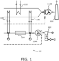
- FIG. 1 is a schematic illustration of an apparatus 102 for improving a reforming process by integrating renewable electrical energy generation therewith according to an embodiment of the present disclosure.
- the apparatus 102 includes a first electrical heater 104, a cold air preheater 106, a hot air preheater 108 and a boiler 110.
- the first electrical heater 104 is configured to partially preheat combustion air using the renewable electrical energy generated by a renewable source.
- the first electrical heater 104 is integrated in between the cold air preheater 106 and the hot air preheater 108 of a process plant that performs the reforming process.
- the first electrical heater 104 is configured to utilize a load based on an availability of the renewable electrical energy received from the renewable source.
- the first electrical heater 104 is configured to provide the preheated combustion air at an outlet of the first electrical heater 104 to the boiler 110 of the process plant based on the load utilized by the first electrical heater 104. If the load utilized by the first electrical heater 104 increases, a temperature of the preheated combustion air at the outlet of the first electrical heater 104 and a load on the boiler 110 are proportionally increased, thereby reducing fuel firing in the boiler 110 and CO 2 emissions.
- the apparatus 102 further includes a second electrical heater 112, a combustion air fan 114A, a flue gas fan 114B, and a flue gas stack 116.
- the second electrical heater 112 utilizes a partial load that is located spatially away from the cold air preheater 106 and the hot air preheater 108 in a waste heat section to increase a preheat temperature of the combustion air at an inlet of the cold air preheater 106 when the renewable electrical energy from the renewable source is supplied to the second electrical heater 112, thereby enabling a higher surface temperature of the cold air preheater 106 and avoiding corrosion resulting from a sulphur dew point.
- FIG. 2 is a flowchart illustrating a method for improving a reforming process by using renewable electrical energy as a heating input to the reforming process according to an embodiment of the present disclosure.
- combustion air is partially preheated using a first electrical heater.
- the first electrical heater is configured to be supplied with the renewable electrical energy generated by a renewable source.
- the first electrical heater is integrated in between a cold air preheater and a hot air preheater of a process plant that performs the reforming process.
- a load is utilized by the first electrical heater based on an availability of the renewable electrical energy received from the renewable source.
- the preheated combustion air is provided at an outlet of the first electrical heater, by the first electrical heater, to a boiler of the process plant based on the load utilized by the first electrical heater. If the load utilized by the first electrical heater increases, a temperature of the preheated combustion air at the outlet of the first electrical heater and a load on the boiler are proportionally increased, thereby reducing fuel firing in the boiler and CO 2 emissions.
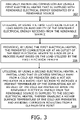
- FIG. 3 is a flowchart illustrating a method for improving a reforming process by integrating renewable electrical energy generation therewith according to an embodiment of the present disclosure.
- combustion air is partially preheated using a first electrical heater that is supplied with renewable electrical energy generated by a renewable source.
- the first electrical heater is integrated in between a cold air preheater and a hot air preheater of a process plant that performs the reforming process.
- a load is utilized by the first electrical heater, based on availability of the renewable electrical energy received from the renewable source.
- the preheated combustion air is provided at an outlet of the first electrical heater, by using the first electrical heater, to a boiler of the process plant based on the load utilized by the first electrical heater. If the load utilized by the first electrical heater increases, a temperature of the preheated combustion air at the outlet of the first electrical heater and a load on the boiler are proportionally increased, thereby reducing fuel firing in the boiler and CO 2 emissions.
- a partial load that is located spatially away from the cold air preheater and the hot air preheater in a waste heat section is utilized by using a second electrical heater to increase a preheat temperature of the combustion air at an inlet of the cold air preheater when the renewable electrical energy from the renewable source is supplied to the second electrical heater, thereby enabling a higher surface temperature of the cold air preheater to be achieved and avoiding corrosion resulting from a Sulphur-dew point.
Landscapes
- Chemical & Material Sciences (AREA)
- Organic Chemistry (AREA)
- Chemical Kinetics & Catalysis (AREA)
- Engineering & Computer Science (AREA)
- Combustion & Propulsion (AREA)
- Inorganic Chemistry (AREA)
- Health & Medical Sciences (AREA)
- General Health & Medical Sciences (AREA)
- Hydrogen, Water And Hydrids (AREA)
Abstract
Description
- The present disclosure relates generally to a reforming process; more specifically, the present disclosure relates to a method and apparatus for improving a reforming process by using renewable electrical energy as a heating input to the reforming process.
- Producing syngas using a process of reforming hydrocarbons at a high temperature is a well-established known (i.e. "classical") technology. Overall, a steam-reforming reaction is highly endothermic and an associated optimum reaction temperature required for the reaction is relatively high, namely in a range of 700°C to 950°C. For achieving this high reaction temperature, heat is supplied via radiation from flames in a furnace box where fuel is burned in burners. Due to a relatively low radiation efficiency of the reaction and a relatively high reaction temperature, a lot of waste heat is available in an effluent flue gas and an effluent reformed process associated with the reaction, respectively.
- Some existing approaches may use part of the aforesaid waste heat for preheating feed and combustion air, and some part of the waste heat for producing superheated steam. For achieving a reasonable thermal efficiency in a process, overall excess steam is produced within the process; a quantity of steam required for implementing the reforming reaction is less than quantity steam produced by the reaction. A high level of heat integration using pinch analysis has thus resulted in a reduction in the steam co-production.
- For maximizing a thermal efficiency of a stack when in operation, it is required to minimize a flue gas temperature to the stack. However, a lower flue gas temperature from a cold air preheater (to the stack) results in a lower metal temperature of a cold air preheater surface at a cold end of the stack. For some cases, this metal temperature is below a sulfur dew point (typically 80° to 110 °C depending upon a SO2 content in the flue gas) of flue gas which results in severe sulfuric acid corrosion. This problem is very common when fuel burned has a relatively high sulfur content and an ambient temperature used is relatively low (cold regions). Therefore, an additional steam-fired air-preheater is required, especially in cold climatic regions, to preheat ambient air before using the preheated ambient air in a cold air preheater in a steam methane reforming (SMR)- waste heat section. The steam-fired preheater adds to additional capital expenditure (CapEx), operational expenditure (OpEx), and CO2 emissions (equivalent to the steam used). Due to higher temperature at which energy input is required, firing of fuel results in significant waste heat being generated.
- Other known approaches may use an electric heater for raising a temperature in a given stack as heating means for heating the combustion air. In such a know approach, electrical power can be used to supply heat at an even higher temperature than is feasible through combustion. However, if the electrical power to be used for such direct heating comes from similar fossil fuel sources, an overall carbon footprint (C-footprint) will be the same or even more since the fuel to electrical power conversion is lower than the fuel to direct heating in the SMR processes. Due to the inherent disadvantage (fuel to electrical conversion to heating by electricity, an efficiency achieved is lower than fuel-to-heat conversion in the SMR process) of using the electrical power for direct heating in the SMR process, it is not applied on a commercial scale.
- In the SMR process, at the cold end of the flue gas waste heat section, heat is normally transferred to a boiler (for steam production) and air preheaters (for preheating combustion air). Generally, the air is preheated from ambient temperature to an elevated temperature in a range of 250°C to 500°C.
- One biggest disadvantage of using renewable electricity (Solar or wind power) in the context of the SMR-process, is an intermittent nature of supply of such renewable electricity (only during daytime for Solar power and only windy hours for wind power).
- Therefore, there is a need to address aforementioned technical drawbacks in existing known technologies in order to improve a reforming process by using renewable electrical energy.
- The present disclosure seeks to provide an approach for improving a reforming process by using renewable electrical energy as a heating input to the reforming process with minimum impact on design of a process plant that is used to perform the reforming process. An aim of the present disclosure is to provide a solution that overcomes at least partially aforesaid problems encountered in prior art and provide an improved method and apparatus for improving a reforming process by using renewable electrical energy as a heating input to the reforming process that reduces fuel firing in a boiler and thereby reduces CO2 emissions. The object of the present disclosure is achieved by solutions provided in the herewith appended independent claims. Advantageous implementations of the present disclosure are further defined in the herewith appended dependent claims.
- According to a first aspect, the present disclosure provides a method for improving a reforming process by using renewable electrical energy as a heating input to the reforming process, wherein the method comprises:
- partially preheating combustion air using a first electrical heater, wherein the first electrical heater is configured to be supplied with the renewable electrical energy generated by a renewable source, wherein the first electrical heater is integrated in between a cold air preheater and a hot air preheater of a process plant that performs the reforming process;
- utilizing, by the first electrical heater, a load based on an availability of the renewable electrical energy received from the renewable source; and
- providing, by the first electrical heater, the preheated combustion air at an outlet of the first electrical heater to a boiler of the process plant based on the load utilized by the first electrical heater, wherein if the load utilized by the first electrical heater increases, a temperature of the preheated combustion air at the outlet of the first electrical heater and a load on the boiler are proportionally increased, thereby reducing fuel firing in the boiler and associated CO2 emissions.
- The method for improving the reforming process by using the renewable electrical energy as the heating input to the reforming process according to present disclosure is of advantage in that the method enables lower fuel firing in the reforming process as the renewable electrical energy is used to preheat the combustion air, thereby reducing CO2 emissions and increasing a lifetime of reforming tubes as it reduces a metal temperature of the reforming tubes in the process plant. Moreover, the method enables a partial preheating of the combustion air to be achieved by using the renewable electrical energy with minimum impact on a design of the process plant, and also ensures seamless transformation from zero to peak renewable electricity input.
- According to a second aspect, the present disclosure provides a method for improving a reforming process by integrating renewable electrical energy generation therewith, the method comprises:
- partially preheating combustion air using a first electrical heater that is supplied with renewable electrical energy generated by a renewable source, wherein the first electrical heater is integrated in between a cold air preheater and a hot air preheater of a process plant that performs the reforming process;
- utilizing, by using the first electrical heater, a load based on an availability of the renewable electrical energy received from the renewable source;
- providing, by using the first electrical heater, the preheated combustion air at an outlet of the first electrical heater to a boiler of the process plant based on the load utilized by the first electrical heater, wherein if the load utilized by the first electrical heater increases, a temperature of the preheated combustion air at the outlet of the first electrical heater and a load on the boiler are proportionally increased, thereby reducing fuel firing in the boiler and CO2 emissions; and
- utilizing, by using a second electrical heater, a partial load that is located spatially away from the cold air preheater and the hot air preheater in a waste heat section to increase a preheat temperature of the combustion air at an inlet of the cold air preheater when the renewable electrical energy from the renewable source is supplied to the second electrical heater, thereby enabling a higher surface temperature of the cold air preheater and avoiding corrosion resulting from a sulphur dew point.
- The method for improving the reforming process by integrating the renewable electrical energy generation therewith according to the present disclosure is of advantage in that the method enables lower fuel firing, thereby reducing CO2 emissions and increasing a lifetime of the reforming tubes as it reduces a metal temperature of reforming tubes in the process plant. Moreover, the method further enables the higher surface temperature in cold end of the cold air preheater to be achieved, and avoids corrosion in the cold air preheater resulting from the sulphur dew point.
- According to a third aspect, the present disclosure provides an apparatus for improving a reforming process by integrating renewable electrical energy therewith, wherein the apparatus comprises:
- a first electrical heater that is configured
- to partially preheat combustion air using the renewable electrical energy generated by a renewable source, wherein the first electrical heater is integrated in between a cold air preheater and a hot air preheater of a process plant that performs the reforming process;
- to utilize a load based on an availability of the renewable electrical energy received from the renewable source; and
- to provide the preheated combustion air at an outlet of the first electrical heater to a boiler of the process plant based on the load utilized by the first electrical heater, wherein if the load utilized by the first electrical heater increases, a temperature of the preheated combustion air at the outlet of the first electrical heater and a load on the boiler are proportionally increased, thereby reducing fuel firing in the boiler and CO2 emissions.
- The apparatus for improving the reforming process by integrating renewable electrical energy therewith according to present disclosure lowers fuel firing, thereby reducing CO2 emissions and increasing a lifetime of the reforming tubes as it reduces a metal temperature of reforming tubes in the process plant. Moreover, the apparatus has less impact on design of the process plant and seamlessly operates with zero to peak renewable electricity input.
- Embodiments of the present disclosure are capable of eliminating the aforementioned drawbacks in existing known approaches for a reforming process by using renewable electrical energy. The advantage of the embodiments according to the present disclosure is that the embodiments enable lower fuel firing, thereby reducing CO2 emissions and increasing lifetime of the reforming tubes as it reduces metal temperature of reforming tubes in the process plant.
- Additional aspects, advantages, features and objects of the present disclosure are made apparent from the drawings and the detailed description of the illustrative embodiments construed in conjunction with the appended claims that follow. It will be appreciated that features of the present disclosure are susceptible to being combined in various combinations without departing from the scope of the present disclosure as defined by the appended claims.
- The summary above, as well as the following detailed description of illustrative embodiments, is better understood when read in conjunction with the appended drawings. To illustrate the present disclosure, exemplary constructions of the disclosure are shown in the drawings. However, the present disclosure is not limited to specific methods and instrumentalities disclosed herein. Moreover, those in the art will understand that the drawings are not to scale. Wherever possible, the same elements have been indicated by identical numbers. Embodiments of the present disclosure will now be described, by way of example only, with reference to the following diagrams wherein:
-
FIG. 1 is a schematic illustration of an apparatus for improving a reforming process by integrating renewable electrical energy generation therewith according to an embodiment of the present disclosure; -
FIG. 2 is a flowchart illustrating a method for improving a reforming process by using renewable electrical energy as a heating input to the reforming process according to an embodiment of the present disclosure; and -
FIG. 3 is a flowchart illustrating a method for improving a reforming process by integrating renewable electrical energy generation therewith according to an embodiment of the present disclosure. - The following detailed description illustrates embodiments of the present disclosure and ways in which they can be implemented. Although some modes of carrying out the present disclosure have been disclosed, those skilled in the art would recognize that other embodiments for carrying out or practicing the present disclosure are also possible.
- According to a first aspect, the present disclosure provides a method for improving a reforming process by using renewable electrical energy as a heating input to the reforming process, wherein the method comprises: partially preheating combustion air using a first electrical heater, wherein the first electrical heater is configured to be supplied with the renewable electrical energy generated by a renewable source, wherein the first electrical heater is integrated in between a cold air preheater and a hot air preheater of a process plant that performs the reforming process; utilizing, by the first electrical heater, a load based on an availability of the renewable electrical energy received from the renewable source; and providing, by the first electrical heater, the preheated combustion air at an outlet of the first electrical heater to a boiler of the process plant based on the load utilized by the first electrical heater, wherein if the load utilized by the first electrical heater increases, a temperature of the preheated combustion air at the outlet of the first electrical heater and a load on the boiler are proportionally increased, thereby reducing fuel firing in the boiler and CO2 emissions.
- The method for improving the reforming process by using the renewable electrical energy as the heating input to the reforming process according to the present disclosure is of advantage in that the method enables lower fuel firing, thereby reducing CO2 emissions and increasing a lifetime of the reforming tubes as it reduces metal temperature of reforming tubes in the process plant.
- The method for improving the reforming process has less impact on the design of the process plant. Moreover, the method ensures seamless operation of the reforming process in the process plant with zero to peak renewable electricity input.
- Optionally, an overall air preheat temperature at the outlet of the hot air preheater, going to burners of the process plant is constant. Optionally, if the hot air preheater utilizes less load, the load available on the boiler situated downstream in flue gas flow direction is high, thereby increasing steam production when the first electrical Heater is taking more load. Such an increase in steam production improves thermal efficiency and lowers operating expenditure (OpEx) of the reforming process.
- For example, for applications where steam value is relatively high (say, more than ∼70% of fuel value), additional steam may be exported which means higher thermal efficiency and lower OpEx, and lower carbon footprint. For applications where steam value is relatively lower, additional steam can be used within the reforming process. More steam used for the reforming process may result in higher feed conversion. This results in reduced fuel firing and/or reduced feed and overall reduced CO2 emissions.
- The fuel for firing may be natural gas, liquid hydrocarbon, coal, tar, petroleum coke, and naphtha.
- Optionally, the method includes preheating the combustion air to a temperature that is in a range of 250°C to 500°C.
- Optionally, the method includes supplying the first electrical heater with the renewable electrical energy in a range of 0 watt (W) to 3000 kilowatt (kW).
- Optionally, the method includes utilizing the preheated combustion air for firing in the reforming process if a reforming temperature is in a range of 750°C to 950°C.
- Optionally, the method includes arranging for a steam to carbon ratio used to be in a range of 1.0 to 10.0.
- Optionally, the method further includes controlling, using a control unit, an outlet temperature of the preheated combustion air provided by the first electrical heater. The control unit is configured to connect the load or the outlet temperature provided by the first electrical heater.
- For example, for each degree (or fraction of a degree) rise in the outlet temperature from the first electrical heater, fuel firing in the reforming process can be reduced accordingly. Optionally, each degree rise in the outlet temperature from the first electrical heater is calculated using a well-defined equation based on estimations/simulations of such scenarios.
- Optionally, the method further includes utilizing, using a second electrical heater, a partial load away from the cold air preheater and the hot air preheater in a waste heat section to increase a preheat temperature of the combustion air at an inlet of the cold air preheater when the renewable electrical energy from the renewable source is supplied to the second electrical heater, thereby enabling a higher surface temperature of the cold air preheater and avoiding corrosion resulting from a sulphur dew point. Moreover, the method may enable more steam production to be achieved by using the second electrical heater.
- Optionally, the second electrical heater is installed at a suction region of a combustion air fan.
- Optionally, the method includes arranging for the load utilized by the second electrical heater to increase for each degree fall in the surface temperature of the cold air preheater. Optionally, each degree fall in the surface temperature of the cold air preheater is calculated using a well-defined equation based on estimations/simulations of such scenarios.
- Optionally, the method includes preheating the combustion air using steam before preheating the combustion air using a flue gas. The combustion air is heated using a third electrical heater that is supplied with the renewable electrical energy generated by the renewable source.
- Optionally, the method includes generating the renewable electrical energy from a renewable energy source. The renewable energy source includes at least one of wind energy, solar energy, hydroelectric source, or biomass source.
- Optionally, the method includes using ambient air in a temperature range of -10°C to 20°C.
- Optionally, the method includes using a sulfur dew point of the flue gas for air preheating in a range of 80°C to 110°C. Optionally, the flue gas from the air preheating is in a range of 120°C to 160°C.
- Optionally, the method includes arranging for the process plant to be a steam methane reforming (SMR) process plant. The steam methane reforming process plant is a part of a chemical plant producing hydrogen (H2), methanol, ammonia, syngas or chemicals in downstream sections
- According to a second aspect, the present disclosure provides a method for improving a reforming process by integrating renewable electrical energy generation therewith, the method comprising: partially preheating combustion air using a first electrical heater that is supplied with renewable electrical energy generated by a renewable source, wherein the first electrical heater is integrated in between a cold air preheater and a hot air preheater of a process plant that performs the reforming process; utilizing, by using the first electrical heater, a load based on an availability of the renewable electrical energy received from the renewable source; providing, by using the first electrical heater, the preheated combustion air at an outlet of the first electrical heater to a boiler of the process plant based on the load utilized by the first electrical heater, wherein if the load utilized by the first electrical heater increases, a temperature of the preheated combustion air at the outlet of the first electrical heater and a load on the boiler are proportionally increased, thereby reducing fuel firing in the boiler and CO2 emissions; and utilizing, by using a second electrical heater, a partial load that is located spatially away from the cold air preheater and the hot air preheater in a waste heat section to increase a preheat temperature of the combustion air at an inlet of the cold air preheater when the renewable electrical energy from the renewable source is supplied to the second electrical heater, thereby enabling a higher surface temperature of the cold air preheater and avoiding corrosion resulting from a sulphur dew point.
- The method for improving the reforming process by integrating the renewable electrical energy generation therewith according to the present disclosure is of advantage in that the method enables a lower fuel firing to be achieved, thereby reducing CO2 emissions and increasing lifetime of the reforming tubes as it reduces a metal temperature of reforming tubes in the process plant. The method further enables a higher surface temperature to be achieved in a cold end of the cold air preheater and avoids corrosion in the cold air preheater resulting from the sulphur dew point.
- Optionally, the method includes controlling the surface temperature of the cold air preheater using a second control unit that controls the surface temperature of the cold air preheater based on the load utilized by the second electrical heater.
- According to a third aspect, the present disclosure provides an apparatus for improving a reforming process by integrating renewable electrical energy therewith: wherein the apparatus comprises: a first electrical heater that is configured to partially preheat combustion air using the renewable electrical energy generated by a renewable source, wherein the first electrical heater is integrated in between a cold air preheater and a hot air preheater of a process plant that performs the reforming process; to utilize a load based on an availability of the renewable electrical energy received from the renewable source; and to provide the preheated combustion air at an outlet of the first electrical heater to a boiler of the process plant based on the load utilized by the first electrical heater, wherein if the load utilized by the first electrical heater increases, a temperature of the preheated combustion air at the outlet of the first electrical heater and a load on the boiler are proportionally increased, thereby reducing fuel firing in the boiler and CO2 emissions.
- The apparatus for improving the reforming process by integrating renewable electrical energy therewith according to present disclosure lowers fuel firing, thereby reducing CO2 emissions and increasing lifetime of the reforming tubes as it reduces metal temperature of reforming tubes in the process plant. Moreover, the apparatus has less impact on design of the process plant and seamlessly operate with zero to peak renewable electricity input.
- A table below includes an example of a green electricity integrated in an existing SMR process using the method of the present disclosure.
Parameters Existing approach Present apparatus H2 Production, Nm3/hr 56000 56000 Steam co-Production, kg/hr 0 0 S/C Ratio 3.05 3.05 Reforming temperature, °C 885 882 Flue Gas Temperature ex Reformer, °C 1051 1046 Air preheat Temperature, °C 450 450 Green Electricity input, kW (Note 1) 0 500 Internal Steam Production, kg/hr 50454 50808 SMR duty, MW 55.4 55.2 CO2 Emission from flue gas, Tons/hr 43.2 43.1 NG Feed + Fuel, Nm3/hr 20700 20664 NG feed, Nm3/hr 20120 20249 NG Fuel, Nm3/hr 579 415 Feed + Fuel saving, Nm3/hr - 36 Feed + Fuel saving, LHV basis, kW - 357 Feed + Fuel saving, % - 0.17% - Optionally, the method enables a saving of approximately 330 kW equivalent of supplementary fuel firing in SMR (e.g., Natural Gas (NG)) for 500 kW of renewable electrical energy, with an approximately 0.25% reduction in CO2 emission from the flue gas and also an increased reformer tube lifetime because of relatively less NG firing. Additionally, the method enables to reduce sulfur dew point underrun/corrosion problems in Cold Air Preheaters (APHs).
- Optionally, a LP steam air preheater is replaced before the combustion air preheater, thereby enabling a minimum metal temperature in cold air preheater to be increased by 20°C, thereby eliminating sulfuric acid corrosion problem if sulfur is used as a fuel.
- Embodiments of the present disclosure substantially eliminate or at least partially address the aforementioned technical drawbacks in existing technologies in improving reforming process by using renewable electrical energy as the heating input to the reforming process.
-
FIG. 1 is a schematic illustration of anapparatus 102 for improving a reforming process by integrating renewable electrical energy generation therewith according to an embodiment of the present disclosure. Theapparatus 102 includes a firstelectrical heater 104, acold air preheater 106, ahot air preheater 108 and aboiler 110. The firstelectrical heater 104 is configured to partially preheat combustion air using the renewable electrical energy generated by a renewable source. The firstelectrical heater 104 is integrated in between thecold air preheater 106 and thehot air preheater 108 of a process plant that performs the reforming process. The firstelectrical heater 104 is configured to utilize a load based on an availability of the renewable electrical energy received from the renewable source. The firstelectrical heater 104 is configured to provide the preheated combustion air at an outlet of the firstelectrical heater 104 to theboiler 110 of the process plant based on the load utilized by the firstelectrical heater 104. If the load utilized by the firstelectrical heater 104 increases, a temperature of the preheated combustion air at the outlet of the firstelectrical heater 104 and a load on theboiler 110 are proportionally increased, thereby reducing fuel firing in theboiler 110 and CO2 emissions. - Optionally, the
apparatus 102 further includes a secondelectrical heater 112, acombustion air fan 114A, aflue gas fan 114B, and aflue gas stack 116. Optionally, the secondelectrical heater 112 utilizes a partial load that is located spatially away from thecold air preheater 106 and thehot air preheater 108 in a waste heat section to increase a preheat temperature of the combustion air at an inlet of thecold air preheater 106 when the renewable electrical energy from the renewable source is supplied to the secondelectrical heater 112, thereby enabling a higher surface temperature of thecold air preheater 106 and avoiding corrosion resulting from a sulphur dew point. -
FIG. 2 is a flowchart illustrating a method for improving a reforming process by using renewable electrical energy as a heating input to the reforming process according to an embodiment of the present disclosure. At astep 202, combustion air is partially preheated using a first electrical heater. The first electrical heater is configured to be supplied with the renewable electrical energy generated by a renewable source. The first electrical heater is integrated in between a cold air preheater and a hot air preheater of a process plant that performs the reforming process. At astep 204, a load is utilized by the first electrical heater based on an availability of the renewable electrical energy received from the renewable source. At astep 206, the preheated combustion air is provided at an outlet of the first electrical heater, by the first electrical heater, to a boiler of the process plant based on the load utilized by the first electrical heater. If the load utilized by the first electrical heater increases, a temperature of the preheated combustion air at the outlet of the first electrical heater and a load on the boiler are proportionally increased, thereby reducing fuel firing in the boiler and CO2 emissions. -
FIG. 3 is a flowchart illustrating a method for improving a reforming process by integrating renewable electrical energy generation therewith according to an embodiment of the present disclosure. At astep 302, combustion air is partially preheated using a first electrical heater that is supplied with renewable electrical energy generated by a renewable source. The first electrical heater is integrated in between a cold air preheater and a hot air preheater of a process plant that performs the reforming process. At astep 304, a load is utilized by the first electrical heater, based on availability of the renewable electrical energy received from the renewable source. At astep 306, the preheated combustion air is provided at an outlet of the first electrical heater, by using the first electrical heater, to a boiler of the process plant based on the load utilized by the first electrical heater. If the load utilized by the first electrical heater increases, a temperature of the preheated combustion air at the outlet of the first electrical heater and a load on the boiler are proportionally increased, thereby reducing fuel firing in the boiler and CO2 emissions. At astep 308, a partial load that is located spatially away from the cold air preheater and the hot air preheater in a waste heat section, is utilized by using a second electrical heater to increase a preheat temperature of the combustion air at an inlet of the cold air preheater when the renewable electrical energy from the renewable source is supplied to the second electrical heater, thereby enabling a higher surface temperature of the cold air preheater to be achieved and avoiding corrosion resulting from a Sulphur-dew point. - Modifications to embodiments of the present disclosure described in the foregoing are possible without departing from the scope of the present disclosure as defined by the accompanying claims. Expressions such as "including", "comprising", "incorporating", "have", "is" used to describe, and claim the present disclosure are intended to be construed in a non-exclusive manner, namely allowing for items, components or elements not explicitly described also to be present. Reference to the singular is also to be construed to relate to the plural.
-
- 102-
- apparatus
- 104-
- first electrical heater
- 106-
- cold air preheater
- 108-
- hot air preheater
- 110-
- boiler
- 112-
- second electrical heater
- 114A-
- combustion air fan
- 114B-
- flue gas fan
- 116-
- flue gas stack
Claims (17)
- A method for improving a reforming process by using renewable electrical energy as a heating input to the reforming process, wherein the method comprises:partially preheating combustion air using a first electrical heater (104), wherein the first electrical heater (104) is configured to be supplied with the renewable electrical energy generated by a renewable source, wherein the first electrical heater (104) is integrated in between a cold air preheater (106) and a hot air preheater (108) of a process plant that performs the reforming process;utilizing, by the first electrical heater (104), a load based on an availability of the renewable electrical energy received from the renewable source; andproviding, by the first electrical heater (104), the preheated combustion air at an outlet of the first electrical heater (104) to a boiler (110) of the process plant based on the load utilized by the first electrical heater (104), wherein if the load utilized by the first electrical heater (104) increases, a temperature of the preheated combustion air at the outlet of the first electrical heater (104) and a load on the boiler (110) are proportionally increased, thereby reducing fuel firing in the boiler (110) and CO2 emissions.
- The method according to claim 1, wherein the method includes preheating the combustion air to a temperature that is in a range of 250°C to 500°C.
- The method according to claim 1 or 2, wherein the method includes supplying the first electrical heater (104) with the renewable electrical energy in a range of 0 watt (W) to 3000 kilowatt (kW).
- The method according to any one of the preceding claims, wherein the method includes utilizing the preheated combustion air for firing in the reforming process if a reforming temperature is in a range of 750°C to 950°C.
- The method according any one of the preceding claims, wherein the method includes arranging for a steam to carbon ratio used to be in a range of 1.0 to 10.0.
- The method according to any one of the preceding claims, wherein the method further includes controlling, using a control unit, an outlet temperature of the preheated combustion air provided by the first electrical heater (104), wherein the control unit is configured to connect the load or the outlet temperature provided by the first electrical heater (104).
- The method according to any one of the preceding claims, wherein the method further includes utilizing, using a second electrical heater (112), a partial load away from the cold air preheater (106) and the hot air preheater (108) in a waste heat section to
increase a preheat temperature of the combustion air at an inlet of the cold air preheater (106) when the renewable electrical energy from the renewable source is supplied to the second electrical heater (112), thereby enabling a higher surface temperature of the cold air preheater (106) to be achieved and avoiding corrosion resulting from a sulphur dew point. - The method according to claim 7, wherein the method includes arranging for the load utilized by the second electrical heater (112) to increase for each degree fall in the surface temperature of the cold air preheater (106).
- The method according to any one of the preceding claims, wherein the method includes preheating the combustion air using steam before preheating using a flue gas, wherein the combustion air is heated using a third electrical heater that is supplied with the renewable electrical energy generated by the renewable source.
- The method according to any one of the preceding claims, wherein the method includes generating the renewable electrical energy from a renewable energy source, wherein the renewable energy source includes at least one of wind energy, solar energy, hydroelectric source, or biomass source.
- The method according to claim 9, wherein the method includes using ambient air in a temperature range of -10°C to 20°C.
- The method according to claim 9, wherein the method includes using a sulfur dew point of the flue gas for air preheating in a range of 80°C to 110°C.
- The method according to claim 9, wherein the flue gas from the air preheating is in a range of 120°C to 160°C.
- The method according to any one of claims 1 to 13, wherein the method includes arranging for the process plant to be a Steam Methane Reforming (SMR) process plant, wherein the Steam Methane Reforming process plant is a part of a chemical plant producing hydrogen (H2), methanol, ammonia, syngas or chemicals in downstream sections.
- A method for improving a reforming process by integrating renewable electrical energy generation therewith, wherein the method comprises:partially preheating combustion air using a first electrical heater (104) that is supplied with renewable electrical energy generated by a renewable source, wherein the first electrical heater (104) is integrated in between a cold air preheater (106) and a hot air preheater (108) of a process plant that performs the reforming process;utilizing, by using the first electrical heater (104), a load based on availability of the renewable electrical energy received from the renewable source;providing, by using the first electrical heater (104), the preheated combustion air at an outlet of the first electrical heater (104) to a boiler (110) of the process plant based on the load utilized by the first electrical heater (104), wherein if the load utilized by the first electrical heater (104) increases, a temperature of the preheated combustion air at the outlet of the first electrical heater (104) and a load on the boiler (110) are proportionally increased, thereby reducing fuel firing in the boiler (110) and CO2 emissions; andutilizing, by using a second electrical heater (112), a partial load that is located spatially away from the cold air preheater (106) and the hot air preheater (108) in a waste heat section to increase a preheat temperature of the combustion air at an inlet of the cold air preheater (106) when the renewable electrical energy from the renewable source is supplied to the second electrical heater (112), thereby enabling a higher surface temperature of the cold air preheater (106) and avoiding corrosion resulting from a Sulphur-dew point.
- The method according to claim 15, wherein the method includes controlling the surface temperature of the cold air preheater (106) using a second control unit that controls the surface temperature of the cold air preheater (106) based on the load utilized by the second electrical heater (112).
- An apparatus (102) for improving a reforming process by integrating renewable electrical energy therewith, wherein the apparatus (102) comprises:
a first electrical heater (104) that is configuredto partially preheat combustion air using the renewable electrical energy generated by a renewable source, wherein the first electrical heater (104) is integrated in between a cold air preheater (106) and a hot air preheater (108) of a process plant that performs the reforming process;to utilize a load based on an availability of the renewable electrical energy received from the renewable source; andto provide the preheated combustion air at an outlet of the first electrical heater (104) to a boiler (110) of the process plant based on the load utilized by the first electrical heater (104), wherein if the load utilized by the first electrical heater (104) increases, a temperature of the preheated combustion air at the outlet of the first electrical heater (104) and a load on the boiler (110) are proportionally increased, thereby reducing fuel firing in the boiler (110) and CO2 emissions.
Priority Applications (2)
| Application Number | Priority Date | Filing Date | Title |
|---|---|---|---|
| EP21020419.4A EP4137449A1 (en) | 2021-08-20 | 2021-08-20 | Method and apparatus for improving a reforming process by using renewable electrical energy as a heating input to the reforming process |
| US17/891,412 US20230072910A1 (en) | 2021-08-20 | 2022-08-19 | Method and apparatus for improving a reforming process by using renewable electrical energy as a heating input to the reforming process |
Applications Claiming Priority (1)
| Application Number | Priority Date | Filing Date | Title |
|---|---|---|---|
| EP21020419.4A EP4137449A1 (en) | 2021-08-20 | 2021-08-20 | Method and apparatus for improving a reforming process by using renewable electrical energy as a heating input to the reforming process |
Publications (1)
| Publication Number | Publication Date |
|---|---|
| EP4137449A1 true EP4137449A1 (en) | 2023-02-22 |
Family
ID=77447670
Family Applications (1)
| Application Number | Title | Priority Date | Filing Date |
|---|---|---|---|
| EP21020419.4A Pending EP4137449A1 (en) | 2021-08-20 | 2021-08-20 | Method and apparatus for improving a reforming process by using renewable electrical energy as a heating input to the reforming process |
Country Status (2)
| Country | Link |
|---|---|
| US (1) | US20230072910A1 (en) |
| EP (1) | EP4137449A1 (en) |
Citations (7)
| Publication number | Priority date | Publication date | Assignee | Title |
|---|---|---|---|---|
| US4576226A (en) * | 1983-04-18 | 1986-03-18 | Lipets Adolf U | Multipass corrosion-proof air preheater |
| US20060231463A1 (en) * | 2005-04-15 | 2006-10-19 | Pham Hoanh N | Process to utilize low-temperature waste heat for the preparation of synthesis gas |
| CN107276126A (en) * | 2017-07-21 | 2017-10-20 | 中国华能集团清洁能源技术研究院有限公司 | A kind of electric heating cold air based on fuel cell is provided multiple forms of energy to complement each other energy supplying system and method |
| WO2017195214A1 (en) * | 2016-05-12 | 2017-11-16 | H2E Power Systems Pvt. Ltd. | Thermally integrated hotbox with passive device |
| US10155661B2 (en) * | 2017-01-27 | 2018-12-18 | L'air Liquide Societe Anonyme Pour L'etude Et L'exploitation Des Procedes Georges Claude | System and methods for improving natural gas usage in steam methane reformers |
| EP3730456A1 (en) * | 2019-04-24 | 2020-10-28 | SABIC Global Technologies B.V. | Use of renewable energy in ammonia synthesis |
| EP3730474A1 (en) * | 2019-04-24 | 2020-10-28 | SABIC Global Technologies B.V. | Use of renewable energy in methanol synthesis |
Family Cites Families (8)
| Publication number | Priority date | Publication date | Assignee | Title |
|---|---|---|---|---|
| US7988948B2 (en) * | 2008-03-17 | 2011-08-02 | Air Products And Chemicals, Inc. | Steam-hydrocarbon reforming method with limited steam export |
| US8007761B2 (en) * | 2008-12-24 | 2011-08-30 | Praxair Technology, Inc. | Carbon dioxide emission reduction method |
| GB0901472D0 (en) * | 2009-01-30 | 2009-03-11 | Johnson Matthey Plc | Hydrogen process |
| US20100242354A1 (en) * | 2009-06-09 | 2010-09-30 | Sundrop Fuels, Inc. | Systems and methods for reactor chemistry and control |
| US20110085967A1 (en) * | 2009-10-14 | 2011-04-14 | Troy Michael Raybold | Hydrogen product method and apparatus |
| ES2566171T3 (en) * | 2012-06-12 | 2016-04-11 | Air Products And Chemicals, Inc. | Production of hydrogen with CO2 capture |
| DE102016218438A1 (en) * | 2016-09-26 | 2018-03-29 | Thyssenkrupp Ag | Process and arrangement for heat energy recovery in plants comprising at least one reformer |
| CN108275653A (en) * | 2018-03-22 | 2018-07-13 | 上海华林工业气体有限公司 | A kind of steam reformer flue gas heat recycling system and method |
-
2021
- 2021-08-20 EP EP21020419.4A patent/EP4137449A1/en active Pending
-
2022
- 2022-08-19 US US17/891,412 patent/US20230072910A1/en not_active Abandoned
Patent Citations (7)
| Publication number | Priority date | Publication date | Assignee | Title |
|---|---|---|---|---|
| US4576226A (en) * | 1983-04-18 | 1986-03-18 | Lipets Adolf U | Multipass corrosion-proof air preheater |
| US20060231463A1 (en) * | 2005-04-15 | 2006-10-19 | Pham Hoanh N | Process to utilize low-temperature waste heat for the preparation of synthesis gas |
| WO2017195214A1 (en) * | 2016-05-12 | 2017-11-16 | H2E Power Systems Pvt. Ltd. | Thermally integrated hotbox with passive device |
| US10155661B2 (en) * | 2017-01-27 | 2018-12-18 | L'air Liquide Societe Anonyme Pour L'etude Et L'exploitation Des Procedes Georges Claude | System and methods for improving natural gas usage in steam methane reformers |
| CN107276126A (en) * | 2017-07-21 | 2017-10-20 | 中国华能集团清洁能源技术研究院有限公司 | A kind of electric heating cold air based on fuel cell is provided multiple forms of energy to complement each other energy supplying system and method |
| EP3730456A1 (en) * | 2019-04-24 | 2020-10-28 | SABIC Global Technologies B.V. | Use of renewable energy in ammonia synthesis |
| EP3730474A1 (en) * | 2019-04-24 | 2020-10-28 | SABIC Global Technologies B.V. | Use of renewable energy in methanol synthesis |
Also Published As
| Publication number | Publication date |
|---|---|
| US20230072910A1 (en) | 2023-03-09 |
Similar Documents
| Publication | Publication Date | Title |
|---|---|---|
| US20240166961A1 (en) | Systems and methods for olefin production in electrically-heated cracking furnace | |
| CN102530865B (en) | Be there is the method for being produced hydrogen by steam reformation petroleum fractions of the production of steam of optimization | |
| JP2572905B2 (en) | Internal reforming molten carbonate fuel cell power generator | |
| US7707837B2 (en) | Steam reforming system | |
| US12365953B2 (en) | Method of operating blast furnace and blast furnace ancillary facility | |
| US20070183966A1 (en) | Waste heat recovery apparatus, waste heat recovery system, and method of recovering waste heat | |
| US20220306465A1 (en) | Reducing Firing and CO2 Emissions in Primary Reformers and Direct Fired Furnaces | |
| CN104284859B (en) | Using natural gas as the improved method of the ammonia-preparing device of raw material | |
| TWI866276B (en) | Process for generating power using a gas turbine fuelled by a carbon free fuel derived from the catalytic cracking of ammonia and method for revamping an ammonia production facility | |
| CA2968373C (en) | Fuel cell system with waste heat recovery for production of high pressure steam | |
| CN102777220A (en) | Hybrid concentrated solar combined cycle power plant and solar reformer for use therein | |
| CN219203212U (en) | Solid oxide fuel cell system | |
| CN106966361B (en) | A hydrogen production reformer | |
| JPH02168570A (en) | Method of generating | |
| CA2921593A1 (en) | E-hybrid reforming | |
| EP4380892B1 (en) | Apparatus for hydrogen production | |
| US20230072910A1 (en) | Method and apparatus for improving a reforming process by using renewable electrical energy as a heating input to the reforming process | |
| CN112864432A (en) | System and method for generating power by using synthesis gas high-temperature fuel cell | |
| JP2008527618A (en) | Preheating device for fuel cell device | |
| JP4233175B2 (en) | Power generation method using coal pyrolysis reaction products | |
| EP4428095A1 (en) | Process for producing hydrogen with electrically heated steam methane reforming | |
| EP3730474A1 (en) | Use of renewable energy in methanol synthesis | |
| CN210163121U (en) | Process system for preparing synthesis gas by converting electrically-heated light hydrocarbon | |
| CN108975271B (en) | Hydrocarbon steam conversion device with pre-conversion function and utilizing high-temperature first-stage gas to preheat mixed gas and conversion process | |
| CN117317320A (en) | Fuel cell system and starting method thereof |
Legal Events
| Date | Code | Title | Description |
|---|---|---|---|
| PUAI | Public reference made under article 153(3) epc to a published international application that has entered the european phase |
Free format text: ORIGINAL CODE: 0009012 |
|
| STAA | Information on the status of an ep patent application or granted ep patent |
Free format text: STATUS: THE APPLICATION HAS BEEN PUBLISHED |
|
| AK | Designated contracting states |
Kind code of ref document: A1 Designated state(s): AL AT BE BG CH CY CZ DE DK EE ES FI FR GB GR HR HU IE IS IT LI LT LU LV MC MK MT NL NO PL PT RO RS SE SI SK SM TR |
|
| RAP3 | Party data changed (applicant data changed or rights of an application transferred) |
Owner name: L'AIR LIQUIDE, SOCIETE ANONYME POUR L'ETUDE ET L'EXPLOITATION DES PROCEDES GEORGES CLAUDE |
|
| STAA | Information on the status of an ep patent application or granted ep patent |
Free format text: STATUS: REQUEST FOR EXAMINATION WAS MADE |
|
| 17P | Request for examination filed |
Effective date: 20230822 |
|
| RBV | Designated contracting states (corrected) |
Designated state(s): AL AT BE BG CH CY CZ DE DK EE ES FI FR GB GR HR HU IE IS IT LI LT LU LV MC MK MT NL NO PL PT RO RS SE SI SK SM TR |
|
| STAA | Information on the status of an ep patent application or granted ep patent |
Free format text: STATUS: EXAMINATION IS IN PROGRESS |
|
| 17Q | First examination report despatched |
Effective date: 20251002 |
|
| STAA | Information on the status of an ep patent application or granted ep patent |
Free format text: STATUS: THE APPLICATION IS DEEMED TO BE WITHDRAWN |