EP4137345B1 - Verfahren und system zur abschätzung der dynamischen kapazität einer batterie für ein elektrofahrzeug - Google Patents
Verfahren und system zur abschätzung der dynamischen kapazität einer batterie für ein elektrofahrzeug Download PDFInfo
- Publication number
- EP4137345B1 EP4137345B1 EP22158579.7A EP22158579A EP4137345B1 EP 4137345 B1 EP4137345 B1 EP 4137345B1 EP 22158579 A EP22158579 A EP 22158579A EP 4137345 B1 EP4137345 B1 EP 4137345B1
- Authority
- EP
- European Patent Office
- Prior art keywords
- battery
- electric vehicle
- voltage
- profiles
- profile
- Prior art date
- Legal status (The legal status is an assumption and is not a legal conclusion. Google has not performed a legal analysis and makes no representation as to the accuracy of the status listed.)
- Active
Links
Images


Classifications
-
- B—PERFORMING OPERATIONS; TRANSPORTING
- B60—VEHICLES IN GENERAL
- B60L—PROPULSION OF ELECTRICALLY-PROPELLED VEHICLES; SUPPLYING ELECTRIC POWER FOR AUXILIARY EQUIPMENT OF ELECTRICALLY-PROPELLED VEHICLES; ELECTRODYNAMIC BRAKE SYSTEMS FOR VEHICLES IN GENERAL; MAGNETIC SUSPENSION OR LEVITATION FOR VEHICLES; MONITORING OPERATING VARIABLES OF ELECTRICALLY-PROPELLED VEHICLES; ELECTRIC SAFETY DEVICES FOR ELECTRICALLY-PROPELLED VEHICLES
- B60L58/00—Methods or circuit arrangements for monitoring or controlling batteries or fuel cells, specially adapted for electric vehicles
- B60L58/10—Methods or circuit arrangements for monitoring or controlling batteries or fuel cells, specially adapted for electric vehicles for monitoring or controlling batteries
- B60L58/16—Methods or circuit arrangements for monitoring or controlling batteries or fuel cells, specially adapted for electric vehicles for monitoring or controlling batteries responding to battery ageing, e.g. to the number of charging cycles or the state of health [SoH]
-
- B—PERFORMING OPERATIONS; TRANSPORTING
- B60—VEHICLES IN GENERAL
- B60L—PROPULSION OF ELECTRICALLY-PROPELLED VEHICLES; SUPPLYING ELECTRIC POWER FOR AUXILIARY EQUIPMENT OF ELECTRICALLY-PROPELLED VEHICLES; ELECTRODYNAMIC BRAKE SYSTEMS FOR VEHICLES IN GENERAL; MAGNETIC SUSPENSION OR LEVITATION FOR VEHICLES; MONITORING OPERATING VARIABLES OF ELECTRICALLY-PROPELLED VEHICLES; ELECTRIC SAFETY DEVICES FOR ELECTRICALLY-PROPELLED VEHICLES
- B60L3/00—Electric devices on electrically-propelled vehicles for safety purposes; Monitoring operating variables, e.g. speed, deceleration or energy consumption
- B60L3/0023—Detecting, eliminating, remedying or compensating for drive train abnormalities, e.g. failures within the drive train
- B60L3/0046—Detecting, eliminating, remedying or compensating for drive train abnormalities, e.g. failures within the drive train relating to electric energy storage systems, e.g. batteries or capacitors
-
- B—PERFORMING OPERATIONS; TRANSPORTING
- B60—VEHICLES IN GENERAL
- B60L—PROPULSION OF ELECTRICALLY-PROPELLED VEHICLES; SUPPLYING ELECTRIC POWER FOR AUXILIARY EQUIPMENT OF ELECTRICALLY-PROPELLED VEHICLES; ELECTRODYNAMIC BRAKE SYSTEMS FOR VEHICLES IN GENERAL; MAGNETIC SUSPENSION OR LEVITATION FOR VEHICLES; MONITORING OPERATING VARIABLES OF ELECTRICALLY-PROPELLED VEHICLES; ELECTRIC SAFETY DEVICES FOR ELECTRICALLY-PROPELLED VEHICLES
- B60L58/00—Methods or circuit arrangements for monitoring or controlling batteries or fuel cells, specially adapted for electric vehicles
- B60L58/10—Methods or circuit arrangements for monitoring or controlling batteries or fuel cells, specially adapted for electric vehicles for monitoring or controlling batteries
-
- G—PHYSICS
- G01—MEASURING; TESTING
- G01R—MEASURING ELECTRIC VARIABLES; MEASURING MAGNETIC VARIABLES
- G01R31/00—Arrangements for testing electric properties; Arrangements for locating electric faults; Arrangements for electrical testing characterised by what is being tested not provided for elsewhere
- G01R31/36—Arrangements for testing, measuring or monitoring the electrical condition of accumulators or electric batteries, e.g. capacity or state of charge [SoC]
- G01R31/3644—Constructional arrangements
- G01R31/3648—Constructional arrangements comprising digital calculation means, e.g. for performing an algorithm
-
- G—PHYSICS
- G01—MEASURING; TESTING
- G01R—MEASURING ELECTRIC VARIABLES; MEASURING MAGNETIC VARIABLES
- G01R31/00—Arrangements for testing electric properties; Arrangements for locating electric faults; Arrangements for electrical testing characterised by what is being tested not provided for elsewhere
- G01R31/36—Arrangements for testing, measuring or monitoring the electrical condition of accumulators or electric batteries, e.g. capacity or state of charge [SoC]
- G01R31/367—Software therefor, e.g. for battery testing using modelling or look-up tables
-
- G—PHYSICS
- G01—MEASURING; TESTING
- G01R—MEASURING ELECTRIC VARIABLES; MEASURING MAGNETIC VARIABLES
- G01R31/00—Arrangements for testing electric properties; Arrangements for locating electric faults; Arrangements for electrical testing characterised by what is being tested not provided for elsewhere
- G01R31/36—Arrangements for testing, measuring or monitoring the electrical condition of accumulators or electric batteries, e.g. capacity or state of charge [SoC]
- G01R31/382—Arrangements for monitoring battery or accumulator variables, e.g. SoC
-
- H—ELECTRICITY
- H01—ELECTRIC ELEMENTS
- H01M—PROCESSES OR MEANS, e.g. BATTERIES, FOR THE DIRECT CONVERSION OF CHEMICAL ENERGY INTO ELECTRICAL ENERGY
- H01M10/00—Secondary cells; Manufacture thereof
- H01M10/42—Methods or arrangements for servicing or maintenance of secondary cells or secondary half-cells
-
- H—ELECTRICITY
- H01—ELECTRIC ELEMENTS
- H01M—PROCESSES OR MEANS, e.g. BATTERIES, FOR THE DIRECT CONVERSION OF CHEMICAL ENERGY INTO ELECTRICAL ENERGY
- H01M10/00—Secondary cells; Manufacture thereof
- H01M10/42—Methods or arrangements for servicing or maintenance of secondary cells or secondary half-cells
- H01M10/48—Accumulators combined with arrangements for measuring, testing or indicating the condition of cells, e.g. the level or density of the electrolyte
-
- H—ELECTRICITY
- H01—ELECTRIC ELEMENTS
- H01M—PROCESSES OR MEANS, e.g. BATTERIES, FOR THE DIRECT CONVERSION OF CHEMICAL ENERGY INTO ELECTRICAL ENERGY
- H01M10/00—Secondary cells; Manufacture thereof
- H01M10/42—Methods or arrangements for servicing or maintenance of secondary cells or secondary half-cells
- H01M10/48—Accumulators combined with arrangements for measuring, testing or indicating the condition of cells, e.g. the level or density of the electrolyte
- H01M10/486—Accumulators combined with arrangements for measuring, testing or indicating the condition of cells, e.g. the level or density of the electrolyte for measuring temperature
-
- B—PERFORMING OPERATIONS; TRANSPORTING
- B60—VEHICLES IN GENERAL
- B60L—PROPULSION OF ELECTRICALLY-PROPELLED VEHICLES; SUPPLYING ELECTRIC POWER FOR AUXILIARY EQUIPMENT OF ELECTRICALLY-PROPELLED VEHICLES; ELECTRODYNAMIC BRAKE SYSTEMS FOR VEHICLES IN GENERAL; MAGNETIC SUSPENSION OR LEVITATION FOR VEHICLES; MONITORING OPERATING VARIABLES OF ELECTRICALLY-PROPELLED VEHICLES; ELECTRIC SAFETY DEVICES FOR ELECTRICALLY-PROPELLED VEHICLES
- B60L2240/00—Control parameters of input or output; Target parameters
- B60L2240/40—Drive Train control parameters
- B60L2240/54—Drive Train control parameters related to batteries
- B60L2240/545—Temperature
-
- B—PERFORMING OPERATIONS; TRANSPORTING
- B60—VEHICLES IN GENERAL
- B60L—PROPULSION OF ELECTRICALLY-PROPELLED VEHICLES; SUPPLYING ELECTRIC POWER FOR AUXILIARY EQUIPMENT OF ELECTRICALLY-PROPELLED VEHICLES; ELECTRODYNAMIC BRAKE SYSTEMS FOR VEHICLES IN GENERAL; MAGNETIC SUSPENSION OR LEVITATION FOR VEHICLES; MONITORING OPERATING VARIABLES OF ELECTRICALLY-PROPELLED VEHICLES; ELECTRIC SAFETY DEVICES FOR ELECTRICALLY-PROPELLED VEHICLES
- B60L2240/00—Control parameters of input or output; Target parameters
- B60L2240/40—Drive Train control parameters
- B60L2240/54—Drive Train control parameters related to batteries
- B60L2240/547—Voltage
-
- B—PERFORMING OPERATIONS; TRANSPORTING
- B60—VEHICLES IN GENERAL
- B60L—PROPULSION OF ELECTRICALLY-PROPELLED VEHICLES; SUPPLYING ELECTRIC POWER FOR AUXILIARY EQUIPMENT OF ELECTRICALLY-PROPELLED VEHICLES; ELECTRODYNAMIC BRAKE SYSTEMS FOR VEHICLES IN GENERAL; MAGNETIC SUSPENSION OR LEVITATION FOR VEHICLES; MONITORING OPERATING VARIABLES OF ELECTRICALLY-PROPELLED VEHICLES; ELECTRIC SAFETY DEVICES FOR ELECTRICALLY-PROPELLED VEHICLES
- B60L2240/00—Control parameters of input or output; Target parameters
- B60L2240/40—Drive Train control parameters
- B60L2240/54—Drive Train control parameters related to batteries
- B60L2240/549—Current
-
- B—PERFORMING OPERATIONS; TRANSPORTING
- B60—VEHICLES IN GENERAL
- B60L—PROPULSION OF ELECTRICALLY-PROPELLED VEHICLES; SUPPLYING ELECTRIC POWER FOR AUXILIARY EQUIPMENT OF ELECTRICALLY-PROPELLED VEHICLES; ELECTRODYNAMIC BRAKE SYSTEMS FOR VEHICLES IN GENERAL; MAGNETIC SUSPENSION OR LEVITATION FOR VEHICLES; MONITORING OPERATING VARIABLES OF ELECTRICALLY-PROPELLED VEHICLES; ELECTRIC SAFETY DEVICES FOR ELECTRICALLY-PROPELLED VEHICLES
- B60L2240/00—Control parameters of input or output; Target parameters
- B60L2240/60—Navigation input
- B60L2240/62—Vehicle position
- B60L2240/622—Vehicle position by satellite navigation
-
- B—PERFORMING OPERATIONS; TRANSPORTING
- B60—VEHICLES IN GENERAL
- B60L—PROPULSION OF ELECTRICALLY-PROPELLED VEHICLES; SUPPLYING ELECTRIC POWER FOR AUXILIARY EQUIPMENT OF ELECTRICALLY-PROPELLED VEHICLES; ELECTRODYNAMIC BRAKE SYSTEMS FOR VEHICLES IN GENERAL; MAGNETIC SUSPENSION OR LEVITATION FOR VEHICLES; MONITORING OPERATING VARIABLES OF ELECTRICALLY-PROPELLED VEHICLES; ELECTRIC SAFETY DEVICES FOR ELECTRICALLY-PROPELLED VEHICLES
- B60L2260/00—Operating Modes
- B60L2260/40—Control modes
- B60L2260/50—Control modes by future state prediction
- B60L2260/52—Control modes by future state prediction drive range estimation, e.g. of estimation of available travel distance
-
- H—ELECTRICITY
- H01—ELECTRIC ELEMENTS
- H01M—PROCESSES OR MEANS, e.g. BATTERIES, FOR THE DIRECT CONVERSION OF CHEMICAL ENERGY INTO ELECTRICAL ENERGY
- H01M2220/00—Batteries for particular applications
- H01M2220/20—Batteries in motive systems, e.g. vehicle, ship, plane
Definitions
- the present subject matter is related in general to systems implemented in an electric vehicle, more particularly, but not exclusively the present subject matter relates to a method for estimating one or more dynamic capacities of a battery in an electric vehicle, for one or more usages of the electric vehicle.
- the electric mobility represents using electric power to enable electric propulsion of vehicles and fleets.
- the fleet operators have reported that one of the biggest challenges faced by the fleet operators is with respect to fleet deployment and maintenance.
- the challenges faced with respect to the fleet deployment and maintenance are estimating longevity and safety of battery of the vehicle.
- the longevity of the battery is a measure of performance and life of the battery.
- a battery pack of the electric vehicle is most expensive and vulnerable component.
- a battery pack is a set of any number (preferably) identical batteries or individual battery cells.
- the battery pack of the electric vehicle is non-adequate to provide efficient performance generally beyond 80% battery health.
- the electric vehicle meets frequent break downs and requires high maintenance when battery health falls beyond the 80%.
- the electric vehicle may also meet some safety issues such as the electric vehicle may catch fire if the battery health falls below 60%.
- SOH State Of Health
- the SOH reflects ability of the battery to deliver and receive energy and power.
- the SOH can also be defined as an expected usable capacity of a battery. In real-time, actual output of the battery is less than the expected usable capacity due to one or more factors affecting the battery.
- the one or more factors may be internal resistance of the battery and losses of energy at varying operating conditions.
- the varying operating conditions of the battery may be charging of the battery and discharging of the battery.
- the battery capacity reduces due to high discharge rate, temperature, ageing of the battery and so on.
- estimation of available energy of the battery of the electric vehicle to predict range of the electric vehicle is based on the SOH of the battery.
- the conventional systems may assume available capacity of the battery pack is equivalent to the capacity indicated by the SOH of the battery.
- the actual output of the battery may be less than the SOH of the battery due to internal resistance, loss of energy due to heat, high discharge rate, temperature, ageing of the electric vehicle and so on.
- the electric vehicle may get heated up from travelling a long distance due to internal resistance in the battery and the battery output may not be equal to the SOH.
- the actual output of the battery may be less than or equal to the SOH of the battery due to different usages of the electric vehicle.
- the different usages of the electric vehicle may include, present usage of the electric vehicle, smoother usage of the electric vehicle and aggressive usage of the electric vehicle.
- a system that may be capable of estimating the actual capacity of the battery that may be useable by the electric vehicle and also to predict longevity of the battery and breakdown index of the vehicle.
- EP 3 283 893 Al discloses an apparatus configured for modelling a state of charge of a secondary electrochemical cell having a Lithium Sulfur chemistry in which capacity can be lost due to active reactant species becoming temporarily inactive in use, wherein the apparatus is configured such that a cell model module and/or a memory effect module adjusts a cell model module in use based on an operational history of a Lithium Sulfur cell to compensate for the prediction of the usable capacity of the cell by the memory effect module.
- US 2021/242 510 A1 discloses a battery management system for an electric vehicle, wherein a battery controller connected to the battery pack is configured to determine an estimated capacity of the battery cell or pack and to validate the estimated capacity.
- a state of health estimating unit is provided which is configured to estimate a state of health of at least one battery cell based on current capacity data and current internal resistance date
- a battery pack comprising: a rechargeable battery module; a battery management system for controlling charging/ discharging of the battery module; wherein the battery module comprises a substantially linear charging and discharging voltage-time profile within at least part of the charging and discharging cycle of the battery module; wherein the battery management system is arranged to calculate a state of charge of the battery module by using the linear charging/discharging characteristics of the battery module.
- the present disclosure relates to an estimation unit for estimating one or more dynamic capacities of a battery for an electric vehicle.
- the proposed unit is configured to receive state of health data of the battery of the electric vehicle. Upon receiving the state of health data, the proposed unit predicts one or more voltage profiles for one or more usages. The one or more dynamic capacities are estimated for the one or more usages using the one or more voltage profiles. Upon estimating the one or more dynamic capacities, longevity index and breakdown index of the battery is determined for the one or more usages using the estimated one or more dynamic capacities.
- the driver may overcome problem related to maintaining the battery of the electric vehicle and reduce overall cost of maintenance.
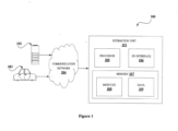
- Figure 1 shows an exemplary environment 100 of an estimation unit 101 for estimating one or more dynamic capacities of a battery for an electric vehicle.
- the exemplary environment 100 may include the estimation unit 101, a battery 102, an electric vehicle 103 and a communication network 104.
- the exemplary environment 100 may be interior of the electric vehicle 103 driven by a driver.
- the electric vehicle may be a car, cab, taxi, motorcycle, truck, bus and so on.
- the proposed estimation unit 101 may be implemented in any vehicle which may be an electric vehicle (103).
- the electric vehicle 103 is a vehicle that uses battery system to run.
- the estimation unit 101 may be implemented in a cloud-based server.
- the estimation unit 101 may be implemented in Battery Energy Storage System (BESS).
- BESS Battery Energy Storage System
- the BESS are rechargeable battery systems that could also be used to store electric energy from kinetic energy of the electric vehicle 103.
- the electric vehicle 103 may be an electric car used for driving from a source point to destination point. The electric car may get stranded before reaching its destination point due to discharge of the battery 102.
- the estimation unit 101 may be used to prevent stranding of the electric vehicle 103 by providing range of distance that can be travelled by the electric vehicle 103. In an embodiment, range of distance of the electric vehicle 103 refers to a distance the electric vehicle 103 or hybrid vehicle may travel before the battery 102 needs to be recharged.
- the estimation unit 101 may be in communication with the battery 102 and the electric vehicle 103.
- the estimation unit 101 may communicate with the battery 102 and the electric vehicle 103 via the communication network 104. In an embodiment, the estimation unit 101 may communicate with each of the battery 102 and the electric vehicle 103 via respective dedicated communication network.
- the communication network 104 may include, without limitation, a direct interconnection, Local Area Network (LAN), Wide Area Network (WAN), Controller Area Network (CAN), wireless network (e.g., using Wireless Application Protocol), the Internet, and the like.
- the estimation unit 101 may include a processor 105, I/O interface 106, and a memory 107.
- the memory 107 may be communicatively coupled to the processor 105.
- the memory 107 stores instructions, executable by the processor 105, which, on execution, may cause the estimation unit 101 for estimating one or more dynamic capacities of the battery 102 for the electric vehicle 103, as disclosed in the present disclosure.
- the memory 107 may include one or more modules 108 and data 109.
- the one or more modules 108 may be configured to perform the steps of the present disclosure using the data 109, for estimating one or more dynamic capacities of the battery 102 for the electric vehicle 103.
- the one or more modules 108 may be configured to perform the steps of the present disclosure using the data 109, for determining longevity index of the battery 102 for the electric vehicle 103. In an embodiment, the one or more modules 108 may be configured to perform the steps of the present disclosure using the data 109, for predicting breakdown index of the battery 102 for the electric vehicle 103. In an embodiment, each of the one or more modules 108 may be a hardware unit which may be outside the memory 107. and coupled with the estimation unit 101.
- the estimation unit 101 may be implemented in a variety of computing systems, such as a laptop computer, a desktop computer, a Personal Computer (PC), a notebook, a smartphone, a tablet, e-book readers, a server, a network server, a cloud-based server and the like.
- the estimation unit 101 may be a dedicated server implemented inside the electric vehicle 103.
- the estimation unit 101 may be associated with multiple electric vehicles through a cloud-based server.
- the estimation unit 101 may communicate with each of the multiple electric vehicles to estimate one or more dynamic capacities of batteries in respective electric vehicles.
- the I/O interface 106 is coupled with the at least one processor 105 through which an input signal or/and an output signal is communicated.
- the input signal and the output signal may represent data received by the estimation unit 101 and data transmitted by the estimation unit 101, respectively.
- the estimation unit 101 may be configured to receive and transmit data via the I/O interface 106.
- the received data may comprise future journey information, geo-location data, real-time battery data, and the like.
- the transmitted data may include the one or more dynamic capacities, the longevity index, the breakdown index and the like.
- the estimation unit 101 may be configured to receive state of health data of the battery 102 of the electric vehicle 103.
- the state of health data is a measurement that reflects general condition of the battery 102 and ability to deliver specified performance compared with a fresh battery.
- the battery 102 may be an Electric Vehicle Battery (EVB) used to power electric motors of the electric vehicle 103 to run the electric vehicle 103.
- the battery 102 may be integrated in the electric vehicle 103.
- the battery 102 may be a detachable part of the electric vehicle 103.
- the electric vehicle 103 is a vehicle that uses one or more electric motors for propulsion.
- the estimation unit 101 may be configured to predict one or more voltage profiles of the battery 102.
- the one or more voltage profiles may be predicted for each of the one or more usages of the electric vehicle 103.
- the one or more usages may be including current usage of the electric vehicle 103, smoother usage of the electric vehicle 103 and aggressive usage of the electric vehicle 103.
- the one or more usages of the electric vehicle 103 may depend on speed of driver. Consider that speed for the current usage of the electric vehicle 103 may be 50km/hr. Similarly, speed of the electric vehicle 103 for the smoother usage may be 40km/hr. Similarly, speed of the electric vehicle 103 for the aggressive usage may be 80km/hr.
- the one or more usages of the electric vehicle 103 may also depend on factors such as driving habits, weather condition, seasons, road conditions and so on.
- the driving habits may be of a driver of the electric vehicle 103, who may be a smooth driver or aggressive driver.
- usage may be aggressive when the road condition is very bumpy with lots of potholes.
- the one or more voltage profiles may be predicted based on at least one of the state of health data, geo-location data and the one or more load profiles of the battery 102.
- the geo-location data may be location of the electric vehicle 103 which may be provided by a Global Positioning System (GPS) associated with the electric vehicle 103.
- GPS Global Positioning System
- the GPS may be integrated in the electric vehicle 103.
- the estimation unit 101 may be configured to estimate the one or more dynamic capacities of the battery 102 for the one or more usages.
- the one or more dynamic capacities is capacity of the battery 102 which may be extractable from the battery 102 for use or running of the electric vehicle 103.
- the capacity of the battery 102 that may be outputted may be 100%.
- actual capacity of the battery that may be outputted may be 90% due to internal resistance, loss of energy during charging of the battery 102, loss of energy during discharging of the battery 102, ageing of the battery 102, temperature of environment of the battery 102 and so on.
- the estimation unit 101 may be configured to estimate the actual capacity of the battery 102 that may be outputted.
- the state of health data comprises capacity state of health of the battery 102 and resistance state of health of the battery 102.
- the capacity state of health is a ratio of current capacity of the battery 102 to original rated capacity of the battery 102.
- the resistance state of health is a ratio between first difference and second difference.
- the first difference may be difference between current internal resistance of the battery 102 and end-of-life value of the battery 102.
- the second difference may be difference between original rated value of internal resistance to original rated end-of-life value of the battery 102.
- the state of health data may be estimated using real-time data.
- the real-time data comprises current data, voltage data, temperature data and state of charge data related to the battery 102.
- the estimation unit 101 may be configured to predict ideal voltage profiles of the battery 102.
- the ideal voltage profiles may be predicted for the one or more usages of the electric vehicle 103.
- the ideal voltage profiles may be predicted based on full Open Circuit Voltage (OCV) profiles, resistance behaviour of the battery 102, and a predefined discharge rate of the battery 102.
- the estimation unit 101 may be configured to predict real-time voltage profile of the battery 102 for current usage of the electric vehicle 103.
- the real-time voltage profile may be predicted based on second OCV profile of the battery 102, resistance behaviour of the battery 102 and a predefined discharge rate of the battery 102.
- the one or more voltage profiles may comprise the ideal voltage profiles and the real-time voltage profile of the battery 102.
- the estimation unit 101 estimates the one or more dynamic capacities for the one or more usages.
- the ideal voltage profiles and the real-time voltage profile may be compared to obtain value of voltage of the battery 102.
- the value of voltage may indicate a predefined lower limit of the voltage below which discharge of the battery 102 may be stopped.
- the estimation unit 101 may be configured to determine longevity index of the battery 102.
- the longevity index may be determined for the one or more usages based on the one or more dynamic capacities.
- longevity index of the battery 102 may indicate lifespan of the battery 102.
- the lifespan of the battery 102 may be provided in terms of number of days. For example, consider that for the current usage of the electric vehicle 103, the longevity index may be 5 years. Similarly, longevity index of the electric vehicle 103 for the smoother usage may be 6 years. Similarly, longevity index of the electric vehicle 103 for the aggressive usage may be 4 years.
- the estimation unit 101 may be configured to predict breakdown index of the battery 102 for the one or more usages.
- the breakdown index may be determined for the one or more usages based on the one or more dynamic capacities and energy information.
- the breakdown index of the electric vehicle 103 may indicate time at which the electric vehicle 103 may breakdown for the one or more usages. For example, consider that for the current usage of the electric vehicle 103, the breakdown may occur after travelling for 4 hours based on the one or more dynamic capacities of the battery 102. Similarly, breakdown of the electric vehicle 103 for the smoother usage may occur after travelling for 5 hours based on the one or more dynamic capacities of the battery 102. Similarly, breakdown of the electric vehicle 103 for the aggressive usage may occur after travelling for 3 hours based on the one or more dynamic capacities. Such information may be depicted from the breakdown index.
- the one or more dynamic capacities, the longevity index and the breakdown index for the one or more usages may be provided via a Human Machine Interface (HMI).
- HMI Human Machine Interface
- the HMI may be a user interface or dashboard that connects a person to a machine, system, or device in the electric vehicle 103.
- the HMI may include a display unit, a speaker, a microphone and so on.
- the display unit may be used for displaying the one or more dynamic capacities, the longevity index and the breakdown index to driver or user.
- speaker for providing audio alerts for breakdowns of the electric vehicle 103, which is identified using the breakdown index.
- microphones could be used by drivers or user to provide voice commands to receive future journey information. to provide breakdown index for the electric vehicle 103.
- the future journey information may include, but is not limited to, distance or length of the future journey, the geo-location related to the future journey, average velocity of the electric vehicle 103 through the future journey and so on.
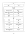
- Figure 2 shows a detailed block diagram of the estimation unit 101 for estimating one or more dynamic capacities of the battery 102 for the electric vehicle 103, in accordance with some embodiments of the present disclosure.
- the data 109 and the one or more modules 108 in the memory 107 of the estimation unit 101 is described herein in detail.
- the one or more modules 108 may include, but are not limited to, a SOH reception module 201, a voltage profile prediction module 202, a dynamic capacity estimation module 203, a longevity index determination module 204, a breakdown index prediction module 205, and one or more other modules 206, associated with the estimation unit 101.
- the data 109 in the memory 107 may include SOH data 207, geo-location data 208, usage data 209, voltage profile data 210, dynamic capacity data 211, longevity index data 212, breakdown index data 213, load profile data 214, energy information data 215, and other data 216 associated with the estimation unit 101.
- One or more modules 108 of the estimation unit 101 function to not only estimate one or more dynamic capacities but also provides the longevity index and the breakdown index of the electric vehicle 103 for the one or more usages.
- the one or more modules 108 along with the data 109, may be implemented in any system, for estimating the one or more dynamic capacities of the electric vehicle 103.
- the first OCV profile estimation unit 304 may be configured to estimate first Open Circuit Voltage (OCV) profiles.
- OCV of the battery 102 is a voltage in which the battery 102 is not connected to any load in a circuit.
- the first OCV profiles may be estimated for each of the one or more usages based on OCV window.
- the OCV window estimation unit 303 may be configured to estimate the OCV window.
- the OCV window may be estimated from the determined voltage window for the current usage.
- the estimated OCV window may not be coinciding with the determined voltage window due to IR drop.
- the IR drop may be obtained due to internal resistance of the battery 102.
- Plot 316 in Figure 3d shows the OCV window.
- the dashed line in plot 316 shows actual OCV of the battery 102 which may be obtained from manufacturer or by performing an experiment to determine the OCV.
- the experiment may include, but is not limited to, low-current OCV test.
- the low-current OCV test uses small amount of current to charge and discharge the battery 102 and measures output voltage which may be approximately equal to the actual OCV.
- the first OCV profile estimation unit 304 may be configured to obtain offset value.
- the offset value may be difference between the actual OCV of the battery 102 and the estimated first OCV profiles of the battery 102.
- the first OCV profile estimation unit 304 may be configured to estimate full OCV profile for the current usage of the electric vehicle 103 using the actual OCV profile.
- Exemplary representation of first OCV profile is shown as plot 317 in Figure 3d .
- the offset value may be used to recreate the full OCV profile for the first OCV profile using the actual OCV profile of the battery 102.
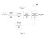
- the ideal voltage profile prediction unit 305 may be configured to predict the ideal voltage profile for the current usage of the electric vehicle 103.
- the ideal voltage profile may be based on the full OCV profile, the resistance behaviour, and a predefined discharge rate of the battery .J 02.
- a discharge rate of the battery 102 may be steady current in amperes which may be taken from the battery 102 of defined capacity over a defined period.
- the predefined discharge rate of the battery 102 may be 20 amperes per hour.
- Exemplary representation of the ideal voltage profile is shown as plot 318 in Figure 3d .
- the ideal voltage profile may be predicted by recreating full voltage window of the battery 102 by using the full OCV profile.
- the voltage profile prediction module 202 may be configured to perform steps indicated in Figures 3b and 3d to predict the ideal voltage profiles for the smoother usage and for the aggressive usage.
- the voltage window for smoother usage may be considered for predicting the ideal voltage profile for the smoother usage.
- the voltage window for aggressive usage may be considered for predicting the ideal voltage profile for the aggressive usage.
- the voltage profile prediction module 202 for predicting the ideal voltage profiles for the smoother usage and the aggressive usage comprises the voltage window determination unit 301, the resistance behaviour determination unit 302, the OCV window estimation unit 303, the first OCV profile estimation unit 304, an ideal voltage profile prediction unit 306 for the smoother usage, and 6an ideal voltage profile prediction unit 307 for the aggressive usage.
- the voltage window determination unit 301 may be configured to determine voltage window of the battery 102 based on the SOH data 207 and the measured load profile of the battery 102 for the smoother usage. Similarly, the voltage window determination unit 301 determines voltage window of the battery 102 for the aggressive usage.
- the SOH data 207 may be obtained from the real-time battery data provided to the voltage window determination unit 301.
- exemplary representation of the voltage window determined for the smoother usage of the electric vehicle 103 may be plot 315 as shown in Figure 3d .
- Exemplary representation of the voltage window determined for the aggressive usage of the electric vehicle 103 may be similar to the plot 315 of Figure 3d with values of voltage measures for the aggressive usage.
- the resistance behaviour determination unit 302 may be configured to determine resistance behaviour of the battery 102.
- the plot 314 of Figure 3d shows the resistance behaviour of battery 102.
- the first OCV profile estimation unit 304 may be configured to estimate the first OCV profiles for the smoother usage and the aggressive usage of the electric vehicle 103.
- the first OCV profiles may be estimated based on the OCV window.
- the OCV window estimation unit 303 may be configured to estimate the OCV window for the smoother usage and the aggressive usage of the electric vehicle 103.
- the OCV window for the smoother usage and the aggressive usage may be similar to the plot 316 of Figure 3d .
- the first OCV profiles for the smoother usage and the aggressive usage may be similar to the plot 317 of Figure 3d .
- the ideal voltage profile prediction unit 306 for smoother usage may be configured to predict the ideal voltage profile for the smoother usage of the electric vehicle 103.
- the ideal voltage profile prediction unit 307 for aggressive usage may be configured to predict the ideal voltage profile for the aggressive usage of the electric vehicle 103.
- the ideal voltage profile for the smoother usage and the aggressive usage may be similar to the plot 318 of Figure 3d .
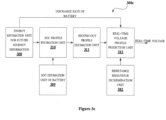
- Figure 3c shows a block diagram to predict the real-time voltage profile of the battery 102.
- the voltage profile prediction module 202 for predicting the real-time voltage profile comprises an energy estimation unit 308 for future journey information, a SOC estimation unit 309 of battery, a SOC profile estimation unit 310, a second OCV profile estimation unit 311, the resistance behaviour determination unit 302, and a real-time voltage profile prediction unit 312.
- the real-time voltage profile indicates voltage determined for the current usage of the electric vehicle 103.
- the energy estimation unit 308 for future journey information of Figure 3c may be configured to estimate amount of energy required to travel for future journey of the electric vehicle 103.
- the electric vehicle 103 may travel from a source point to a destination point which may be referred as the future journey of the electric vehicle 103.
- information about the future journey of the electric vehicle 103 may be obtained from driver of the electric vehicle 103 via the HMI.
- the SOC profile estimation unit 310 may be configured to determine SOC profile of the battery 102.
- the energy required for the future journey and start SOC of the battery 102 may be used to determine the SOC profile.
- the SOC estimation unit 309 of the battery 102 may be configured to estimate the start SOC of the battery 102.
- the second OCV profile estimation unit 311 may be configured to estimate second OCV profile of the battery 102.
- the second OCV profile may be estimated based on the SOC profile and predicted load profile.
- the predicted load profile indicates values of current estimated for the geo-location data 208, future journey and velocity of the electric vehicle 103.
- the geo-location data 208 may be location of the electric vehicle 103 obtained via the GPS.
- the location of the electric vehicle 103 may be referred as the geo-location data 208 and is stored in the memory 107.
- the future journey of the electric vehicle 103 may be path or direction from a source point to a destination point.
- the velocity of the electric vehicle 103 may be speed of the electric vehicle 103 on route of the future journey obtained from Map Application Programming Interface (Map API).
- Map API Map Application Programming Interface
- the Map API also known as mapping API
- the second OCV profile may be estimated using steps indicated in Figure 3d .
- the real-time voltage profile prediction unit 312 may be configured to predict the real-time voltage profile of the battery 102 for the current usage of the electric vehicle 103.
- the real-time voltage profile may be predicted based on the second OCV profile, the resistance behaviour of the battery 102 and the predefined discharge rate of the battery 102.
- the dynamic capacity estimation module 203 may be configured to estimate one or more dynamic capacities of the battery 102.
- the one or more dynamic capacities may be energy that may be extractable from the battery 102 for usages.
- the one or more dynamic capacities may be estimated for the one or more usages.
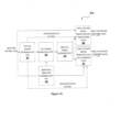
- the real-time data may be provided to the battery pack model 401 to obtain the capacity state of health of the battery 102 and the resistance state of the health of the battery 102 as shown in Figure 4a .
- the capacity state of health of the battery 102 is referred as SOHQ as shown in Figure 4a .
- the resistance state of health of the battery 102 is referred as SOHR as shown in Figure 4a .
- the SOHQ and the SOHR is provided for prediction of ideal voltage profiles.
- the ideal voltage profile prediction unit 402 may be configured to predict the ideal voltage profiles.
- the SOHQ and the SOHR along with the geo-location data 208 and the predicted load profile is provided for prediction of the real-time voltage profile.
- the real-time voltage profile prediction unit 403 may be configured to predict the real-time voltage profile.
- the ideal voltage profile and the real-time voltage profile may be provided for estimation of dynamic capacity of the current usage of the electric vehicle 103.
- the dynamic capacity estimation unit 404 for one or more usages may be configured to estimate the one or more dynamic capacities for the one or more usages of the electric vehicle 103.
- the one or more dynamic capacities for the one or more usages may include dynamic capacity for the smoother usage, dynamic capacity for the current or present usage and dynamic capacity for the aggressive usage.
- the ideal voltage profile and the real-time voltage profile may be compared to obtain a value of voltage of the battery 102.
- the value of voltage may drop to reach a predefined lower limit of voltage of the battery 102.
- the predefined lower limit of voltage of the battery 102 indicates a voltage value for which Battery Management System (BMS) stops discharging of the battery 102.
- BMS Battery Management System
- the BMS is any electronic system that manages a rechargeable battery by protecting the battery from operating outside its safe operating area or the predefined lower limit.
- the dynamic capacity estimation unit 404 may be configured to identify total capacity discharged by the battery 102.
- the total capacity discharged may be amount of energy which may be drawn from the battery 102.
- the dynamic capacity estimation unit 404 may be configured to compare the total capacity discharged for corresponding usage with the capacity state of health of the battery 102. Further upon comparison, dynamic capacity of the battery 102 for the current usage may be determined.
- Line 407 in plot 405 of Figure 4b shows the dynamic capacity of the battery 102 for the current usage which may be less than dynamic capacity of the battery 102 in ideal condition as shown as line 406 in the plot 405 of Figure 4b .
- the ideal condition may include, but is not limited to, no internal resistance in the battery 102, ideal environment condition which is between 20 degree Celsius to 60 degree Celsius and so on.
- the dynamic capacity of the battery 102 for the smoother usage may be more than the dynamic capacity of the current usage and less than or equal to the dynamic capacity of the battery 102 in the ideal condition.
- the dynamic capacity of the battery 102 for the aggressive usage may be less than the dynamic capacity of the current usage and the smoother usage, and much lesser than the dynamic capacity of the battery 102 in the ideal condition.
- the dynamic capacity for the one or more usages may be referred as the dynamic capacity data 211 and stored in the memory 107.
- the longevity index determination module 204 may be configured to determine longevity index of the battery 102.
- the longevity index may be determined for the one or more usages.
- the longevity of the battery 102 is lifespan of the battery 102 in terms of number of days or energy throughput.
- the energy throughput may be total amount of energy the battery 102 may be expected to store and deliver over its lifespan.
- the dynamic capacity estimated over the energy throughput increases for the smoother usage.
- the dynamic capacity estimated over the energy throughput may be less for the current usage.
- the dynamic capacity estimated over the energy throughput may be least for the aggressive usage.
- the dynamic capacity may be fitted using a Weibull distribution curve using Weibull parameters obtained from Weibull parameters provide unit 501.
- Weibull distribution is a continuous probability distribution and is used to assess product reliability, analyze life data and times of model failure.
- Weibull parameters may include, but is not limited to, two parameter Weibull and three parameter Weibull.
- the two parameter Weibull may be often used in failure analysis.
- the three parameter Weibull may be used for describing shape, scale and threshold parameters of a product.
- dynamic capacity degradation may be estimated based on the Weibull distribution curves for the one or more usages.
- lower limit of dynamic capacity may be pre-decided based on the current or present usage of the electric vehicle 103.
- total energy throughput for each of the one or more usages may be observed and as per daily usage the longevity index may be determined. For example, consider dashed line 502 in plot 500 of Figure 5 . The dashed line 502 shows maximum longevity of the battery 102 in the ideal condition. Similarly, solid line 503 in the plot 500 of Figure 5 shows the longevity of the battery 102 for the current usage of the electric vehicle 103, which is less than the longevity of the battery 102 in the ideal condition.
- dashed line 504 in the plot 500 of Figure 5 shows the longevity of the battery 102 for the smoother usage of the electric vehicle 103, which is almost equal to the longevity of the battery 102 in the ideal condition.
- dashed line 505 in the plot 500 of Figure 5 shows the longevity of the battery 102 for the aggressive usage of the electric vehicle 103, which is very less compared to the longevity of the battery 102 in the ideal condition.
- the longevity of the battery 102 for the current usage may be 5 years.
- the longevity of the battery 102 for the smoother usage may be 6 years.
- the longevity of the battery 102 for the aggressive usage may be 4 years.
- the longevity of the battery 102 for the one or more usages may be referred as the longevity index data 212 and is stored in the memory 107.
- the breakdown index prediction module 205 may be configured to predict breakdown index of the battery 102.
- the breakdown index may be predicted for the one or more usages based on the one or more dynamic capacities and energy information.
- the energy information may include, but is not limited to, driver behaviour, the geo-location data 208, velocity of the electric vehicle 103, length of the future journey and so on.
- the driver behaviour may indicate driving pattern of the driver for the electric vehicle 103.
- velocity of the electric vehicle 103 may be average road velocity and may be obtained from the map API.
- the energy information related to the driver and the electric vehicle 103 may be referred as the energy information data 215 and is stored in the memory 107.
- the breakdown index prediction module 205 may be configured to predict energy and rate of the energy that may be required from the battery 102 with respect to the future journey information.
- the future journey information may be information about length of the future journey and location of the source point and the destination point.
- the breakdown index prediction module 205 may be configured to predict the breakdown index for each of the one or more usages.
- the breakdown index of the electric vehicle 103 may be predicted in terms of time as shown in Figure 6 . For example, for the future journey information, the electric vehicle 103 for the current or average usage may breakdown around 5 hours after travelling.
- the electric vehicle 103 for the smoother usage may breakdown around 6 hours after travelling.
- the electric vehicle 103 for the aggressive usage may breakdown around 4 hours after travelling.
- dashed line 601 in plot 600 of Figure 6 shows breakdown for the aggressive usage of the electric vehicle 103.
- solid line 602 in the plot 600 of Figure 6 shows breakdown for the current or average usage of the electric vehicle 103.
- dashed line 603 in plot 600 of Figure 6 shows breakdown for the smoother usage of the electric vehicle 103.
- the breakdown index predicted for the one or more usages may be referred as the breakdown index data 213 and stored in the memory 107.
- the other data 216 may store data, including temporary data and temporary files, generated by modules for performing the various functions of the estimation unit 101.
- the one or more modules 108 may also include other modules 206 to perform various miscellaneous functionalities of the estimation unit 101. It will be appreciated that such modules may be represented as a single module or a combination of different modules.
- Figure 7 illustrates a flow diagram showing an exemplary method for estimating the one or more dynamic capacities of the battery 102 for the electric vehicle 103, in accordance with some embodiments of present disclosure.
- the SOH reception module 201 may be configured to receive the SOH data 207.
- the SOH data 207 includes the capacity state of health of the battery 102 and the resistance state of health of the battery 102.
- the SOH data 207 may be based on the real-time battery data.
- the real-time battery data may be collected from catalogue of the battery 102 of the electric vehicle 103.
- the real-time battery data comprises the current data, the voltage data, the temperature data and the SOC data related to the battery 102 of the electric vehicle 103.
- the SOH reception module 201 may be configured to determine the SOH data 207 using the battery pack model 401.
- the SOH data 207 may be determined using machine learning methods such as neural network, support vector regression, fuzzy logic and so on.
- the voltage profile prediction module 202 may be configured to predict the one or more voltage profiles of the battery 102.
- the one or more voltage profiles comprises the ideal voltage profiles and the real-time voltage profile.
- the ideal voltage profiles may be predicted using the capacity state of health data, the resistance state of health data and the load profile data 214.
- the real-time voltage profile may be predicted using the SOH data 207, the geo-location data 208 of the electric vehicle 103, the load profile data 214 of the battery 102.
- the dynamic capacity estimation module 203 may be configured to estimate the one or mor dynamic capacities of the battery 102.
- the one or more dynamic capacities may be estimated for the one or more usages.
- the one or more dynamic capacities may be the capacity or energy that is extractable from the battery 102 for the one or more usages. For example, consider the dynamic capacity that may be extractable from the battery 102 for the current usage may be 80%. Similarly, the dynamic capacity that may be extractable from the battery 102 for the smoother usage may be 90%. Similarly, the dynamic capacity that may be extractable from the battery 102 for the aggressive usage may be 70%.
- the longevity index determination module 204 may be configured to determine the longevity index of the battery 102.
- the longevity index may be determined for the one or more usages.
- the longevity index may be determined using the Weibull curve.
- the longevity index may be provided in terms of number of days or the energy throughput as required by user or driver of the electric vehicle 103.
- one or more other techniques known to a person skilled in art, may be implemented to determine the longevity index using the one or more dynamic capacities.
- the one or more other techniques which may be used to determine the longevity index of the battery 102 may include, but are not limited to, Artificial Intelligence (AI) model, surface fit, look-up table obtained based on historic data of the electric vehicle 103 and so on.
- AI Artificial Intelligence
- the order in which the method 700 is described may not intended to be construed as a limitation, and any number of the described method blocks can be combined in any order to implement the method. Additionally, individual blocks may be deleted from the methods without departing from the scope of the subject matter described herein. Furthermore, the method can be implemented in any suitable hardware, software, firmware, or combination thereof.
- the processor 802 may be disposed in communication with one or more input/output (I/O) devices 809 and 810 via I/O interface 801.
- the I/O interface 801 may employ communication protocols/methods such as, without limitation, audio, analog, digital, monaural, RCA, stereo, IEEE-1394, serial bus, universal serial bus (USB), infrared, PS/2, BNC, coaxial, component, composite, digital visual interface (DVI), high-definition multimedia interface (HDMI), RF antennas, S-Video, VGA, IEEE 802.n /b/g/n/x, Bluetooth, cellular (e.g., code-division multiple access (CDMA), high-speed packet access (HSPA+), global system for mobile communications (GSM), long-term evolution (LTE), WiMax, or the like), etc.
- CDMA code-division multiple access
- HSPA+ high-speed packet access
- GSM global system for mobile communications
- LTE long-term evolution
- WiMax wireless wide area network
- the computer system 800 may communicate with one or more I/O devices 809 and 810.
- the input devices 809 may be an antenna, keyboard, mouse, joystick, (infrared) remote control, camera, card reader, fax machine, dongle, biometric reader, microphone, touch screen, touchpad, trackball, stylus, scanner, storage device, transceiver, video device/source, etc.
- the output devices 810 may be a printer, fax machine, video display (e.g., cathode ray tube (CRT), liquid crystal display (LCD), light-emitting diode (LED), plasma, Plasma display panel (PDP), Organic light-emitting diode display (OLED) or the like), audio speaker, etc.
- CTR cathode ray tube
- LCD liquid crystal display
- LED light-emitting diode
- PDP Plasma display panel
- OLED Organic light-emitting diode display
- the computer system 800 may consist of the estimation unit 101.
- the processor 802 may be disposed in communication with the communication network 811 via a network interface 803.
- the network interface 803 may communicate with the communication network 811.
- the network interface 803 may employ connection protocols including, without limitation, direct connect, Ethernet (e.g., twisted pair 10/100/1000 Base T), transmission control protocol/internet protocol (TCP/IP), token ring, IEEE 802.11a/b/g/n/x, etc.
- the communication network 811 may include, without limitation, a direct interconnection, local area network (LAN), wide area network (WAN), wireless network (e.g., using Wireless Application Protocol), the Internet, etc.
- the computer system 800 may communicate with the battery 102 and the electric vehicle 103 for estimating one or more dynamic capacities of the battery 102 for the electric vehicle 103, for one or more usages of the electric vehicle 103.
- the network interface 803 may employ connection protocols include, but not limited to, direct connect, Ethernet (e.g., twisted pair 10/100/1000 Base T), transmission control protocol/internet protocol (TCP/IP), token ring, IEEE 802.11a/b/g/n/x, etc.
- the communication network 811 includes, but is not limited to, a direct interconnection, an e-commerce network, a peer to peer (P2P) network, local area network (LAN), wide area network (WAN), wireless network (e.g., using Wireless Application Protocol), the Internet, Wi-Fi, and such.
- the first network and the second network may either be a dedicated network or a shared network, which represents an association of the different types of networks that use a variety of protocols, for example, Hypertext Transfer Protocol (HTTP), Transmission Control Protocol/Internet Protocol (TCP/IP), Wireless Application Protocol (WAP), etc., to communicate with each other.
- the first network and the second network may include a variety of network devices, including routers, bridges, servers, computing devices, storage devices, etc.
- the processor 802 may be disposed in communication with a memory 805 (e.g., RAM, ROM, etc. not shown in Figure 8 ) via a storage interface 804.
- the memory 805 bears the memory 107.
- the storage interface 804 may connect to memory 805 including, without limitation, memory drives, removable disc drives, etc., employing connection protocols such as, serial advanced technology attachment (SATA), Integrated Drive Electronics (IDE), IEEE-1394, Universal Serial Bus (USB), fibre channel, Small Computer Systems Interface (SCSI), etc.
- the memory drives may further include a drum, magnetic disc drive, magneto-optical drive, optical drive, Redundant Array of Independent Discs (RAID), solid-state memory devices, solid-state drives, etc.
- the operating system 807 may facilitate resource management and operation of the computer system 800.
- Examples of operating systems include, without limitation, APPLE MACINTOSH ® OS X, UNIX ® , UNIX-like system distributions (E.G., BERKELEY SOFTWARE DISTRIBUTION TM (BSD), FREEBSD TM , NETBSD TM , .OPENBSD TM , etc.), LINUX DISTRIBUTIONS TM (E.G., RED HAT TM , UBUNTU TM , KUBUNTU TM , etc.), IBM TM OS/2, MICROSOFT TM WINDOWS TM (XP TM , VISTA TM /7/8, 10 etc.), APPLE ® IOS TM , GOOGLE ® ANDROID TM , BLACKBERRY ® OS, or the like.
- the computer system 800 may implement a web browser 808 stored program component.
- the web browser 808 may be a hypertext viewing application, such as Microsoft Internet Explorer, Google Chrome, Mozilla Firefox, Apple Safari, etc. Secure web browsing may be provided using Hypertext Transport Protocol Secure (HTTPS), Secure Sockets Layer (SSL), Transport Layer Security (TLS), etc. Web browser 808 may utilize facilities such as AJAX, DHTML, Adobe Flash, JavaScript, Java, Application Programming Interfaces (APIs), etc.
- the computer system 800 may implement a mail server stored program component.
- the mail server may be an Internet mail server such as Microsoft Exchange, or the like.
- an embodiment means “one or more (but not all) embodiments of the invention(s)" unless expressly specified otherwise.
Landscapes
- Engineering & Computer Science (AREA)
- Power Engineering (AREA)
- Sustainable Development (AREA)
- Sustainable Energy (AREA)
- Electrochemistry (AREA)
- General Chemical & Material Sciences (AREA)
- Chemical & Material Sciences (AREA)
- Life Sciences & Earth Sciences (AREA)
- Manufacturing & Machinery (AREA)
- Chemical Kinetics & Catalysis (AREA)
- Transportation (AREA)
- Mechanical Engineering (AREA)
- Physics & Mathematics (AREA)
- General Physics & Mathematics (AREA)
- Secondary Cells (AREA)
- Charge And Discharge Circuits For Batteries Or The Like (AREA)
- Electric Propulsion And Braking For Vehicles (AREA)
- Tests Of Electric Status Of Batteries (AREA)
Claims (10)
- Verfahren zum Schätzen einer oder mehrerer dynamischer Kapazitäten einer Batterie (102) für ein Elektrofahrzeug (103) für eine oder mehrere Nutzungen des Elektrofahrzeugs (103), umfassend:Empfangen von Gesundheitszustandsdaten der Batterie (102) des Elektrofahrzeugs (103) durch eine Schätzeinheit (101), wobeidie Gesundheitszustandsdaten einen Kapazitätsgesundheitszustand (SOHQ) und einen Widerstandsgesundheitszustand (SOHR) der Batterie (102) umfassen;Vorhersagen von idealen Spannungsprofilen und eines Echtzeit-Spannungsprofils der Batterie (102) durch die Schätzeinheit (101), wobeidie idealen Spannungsprofile für jede der einen oder mehreren Nutzungen des Elektrofahrzeugs (103) basierend auf dem Kapazitätsgesundheitszustand (SOHQ), dem Widerstandsgesundheitszustand (SOHR) und einem oder mehreren Lastprofilen der Batterie (102) vorhergesagt werden, wobeidas Echtzeit-Spannungsprofil basierend auf dem Kapazitätsgesundheitszustand (SOHQ), dem Widerstandsgesundheitszustand (SOHR), Geolokalisierungsdaten (208) des Elektrofahrzeugs (103) und einem oder mehreren Lastprofilen der Batterie (102) vorhergesagt wird; undSchätzen der einen oder mehreren dynamischen Kapazitäten der Batterie (102) für die eine oder mehreren Nutzungen durch die Schätzeinheit (101) basierend auf den idealen Spannungsprofilen und dem Echtzeit-Spannungsprofil, wobeidie eine oder mehreren Nutzungen des Elektrofahrzeugs (103) eine aktuelle Nutzung des Elektrofahrzeugs (103), eine gleichmäßigere Nutzung des Elektrofahrzeugs (103) und eine aggressive Nutzung des Elektrofahrzeugs (103) beinhalten, wobei die eine oder mehreren dynamischen Kapazitäten einer Kapazität der Batterie (102) entsprechen, die aus der Batterie (102) zur Nutzung oder zum Betrieb des Elektrofahrzeugs (103) extrahierbar ist, wobeijedes der idealen Spannungsprofile Spannungen angibt, die für eine entsprechende Nutzung aus der einen oder den mehreren Nutzungen des Elektrofahrzeugs (103) bestimmt werden, wobeidas Vorhersagen der idealen Spannungsprofile Folgendes umfasst:Bestimmen eines Spannungsfensters der Batterie (102) für jede der einen oder mehreren Nutzungen des Elektrofahrzeugs (103) aus einem gemessenen Lastprofil des einen oder der mehreren Lastprofile, wobei das gemessene Lastprofil Werte des Stroms angibt, die für eine aktuelle Strecke und Geschwindigkeit des Elektrofahrzeugs (103) gemessen werden;Bestimmen eines Widerstandsverhaltens der Batterie (102) durch Vergleichen des SOC und des Widerstandsgesundheitszustands (SOHR);Schätzen erster Leerlaufspannungsprofile (OCV-Profile) der Batterie (102) basierend auf OCV-Fenstern, die aus dem bestimmten Spannungsfenster basierend auf dem Widerstandsverhalten geschätzt werden, für jedes des einen oder der mehreren Nutzungsprofile;Schätzen vollständiger OCV-Profile der Batterie (102) basierend auf einem Versatzverfahren, wobeidas Versatzverfahren eine durchschnittliche Differenz zwischen den vollständigen OCV-Profilen und den geschätzten ersten OCV-Profilen angibt; undVorhersagen der idealen Spannungsprofile für jedes des einen oder der mehreren Nutzungsprofile basierend auf den vollständigen OCV-Profilen, dem Widerstandsverhalten und einer vordefinierten Entladungsrate der Batterie (102), und wobeidas Echtzeit-Spannungsprofil Spannung angibt, die für die aktuelle Nutzung des Elektrofahrzeugs (103) bestimmt wird, wobeidas Vorhersagen des Echtzeit-Spannungsprofils Folgendes umfasst:Bestimmen eines SOC-Profils der Batterie (102) für zukünftige Fahrtinformationen;Schätzen eines zweiten OCV-Profils der Batterie (102) basierend auf dem bestimmten SOC-Profil und dem vorhergesagten Lastprofil des einen oder der mehreren Lastprofile für die zukünftigen Fahrtinformationen des Elektrofahrzeugs (103) und einem Start-SOC der Batterie (102), wobeidas vorhergesagte Lastprofil Werte des Stroms angibt, die für Geolokalisierungsdaten (208), eine zukünftige Fahrtstrecke und Geschwindigkeit des Elektrofahrzeugs (103) geschätzt werden; undVorhersagen des Echtzeit-Spannungsprofils basierend auf dem zweiten OCV-Profil, dem Widerstandsverhalten der Batterie (102) und einer vordefinierten Entladungsrate der Batterie (102).
- Verfahren nach Anspruch 1, ferner umfassend:
Bestimmen eines Langlebigkeitsindex der Batterie (102) für die eine oder mehreren Nutzungen durch die Schätzeinheit (101) basierend auf der geschätzten einen oder den geschätzten mehreren dynamischen Kapazitäten. - Verfahren nach Anspruch 1, ferner umfassend:
Vorhersagen eines Ausfallindex der Batterie (102) für die eine oder mehreren Nutzungen durch die Schätzeinheit (101) basierend auf der geschätzten einen oder den geschätzten mehreren dynamischen Kapazitäten und Energieinformationen, wobei die Energieinformationen Energie und Rate der Energie angeben, die von der Batterie (102) in Bezug auf zukünftige Fahrtinformationen des Elektrofahrzeugs (103) benötigt wird. - Verfahren nach Anspruch 1, wobeidie Gesundheitszustandsdaten auf einem Batteriepackmodell (401) basieren, das sich auf die Batterie bezieht, wobeidas Batteriepackmodell (401) unter Verwendung von Echtzeit-Batteriedaten, die Stromdaten, Spannungsdaten, Temperaturdaten und Ladezustandsdaten (SOC-Daten) umfassen, die sich auf die Batterie (102) beziehen, periodisch aktualisiert wird.
- Verfahren nach Anspruch 1, wobei
das Schätzen der einen oder der mehreren dynamischen Kapazitäten für die eine oder die mehreren Nutzungen ferner Folgendes umfasst:Vergleichen von idealen Spannungsprofilen und einem Echtzeit-Spannungsprofil, um einen Spannungswert der Batterie (102) zu erhalten, wobei die Spannung fällt, um eine vordefinierte Untergrenze der Spannung zu erreichen, wobeidie vordefinierte Untergrenze angibt, wann das Batteriemanagementsystem (BMS) die Entladung der Batterie (102) stoppt;Identifizieren der von der Batterie (102) entladenen Gesamtkapazität basierend auf dem Spannungswert der Batterie (102); undVergleichen der Gesamtkapazität für die entsprechende Nutzung aus der einen oder den mehreren Nutzungen mit dem Kapazitätsgesundheitszustand der Batterie (102), um die eine oder die mehreren dynamischen Kapazitäten für die eine oder die mehreren Nutzungen zu schätzen. - Schätzeinheit (101) zum Schätzen einer oder mehrerer dynamischer Kapazitäten einer Batterie (102) für ein Elektrofahrzeug (103) für eine oder mehrere Nutzungen des Elektrofahrzeugs (103), wobei die Schätzeinheit (101) umfasst:einen Prozessor (105); undeinen Speicher (107), der kommunikativ mit dem Prozessor (105) gekoppelt ist, wobei der Speicher (107) prozessorausführbare Anweisungen speichert, die bei Ausführung den Prozessor (105) veranlassen zum:Empfangen von Gesundheitszustandsdaten der Batterie (102) des Elektrofahrzeugs (103), wobeidie Gesundheitszustandsdaten einen Kapazitätsgesundheitszustand (SOHQ) und einen Widerstandsgesundheitszustand (SOHR) der Batterie (102) umfassen;Vorhersagen von idealen Spannungsprofilen und eines Echtzeit-Spannungsprofils der Batterie (102), wobeidie idealen Spannungsprofile für jede der einen oder mehreren Nutzungen des Elektrofahrzeugs (103) basierend auf dem Kapazitätsgesundheitszustand (SOHQ), dem Widerstandsgesundheitszustand (SOHR) und einem oder mehreren Lastprofilen der Batterie (102) vorhergesagt werden, wobeidas Echtzeit-Spannungsprofil basierend auf dem Kapazitätsgesundheitszustand (SOHQ), dem Widerstandsgesundheitszustand (SOHR), Geolokalisierungsdaten (208) des Elektrofahrzeugs (103) und einem oder mehreren Lastprofilen der Batterie (102) vorhergesagt wird; undSchätzen der einen oder mehreren dynamischen Kapazitäten der Batterie (102) für die eine oder mehreren Nutzungen basierend auf den idealen Spannungsprofilen und dem Echtzeit-Spannungsprofil, wobeidie eine oder mehreren Nutzungen des Elektrofahrzeugs (103) eine aktuelle Nutzung des Elektrofahrzeugs (103), eine gleichmäßigere Nutzung des Elektrofahrzeugs (103) und eine aggressive Nutzung des Elektrofahrzeugs (103) beinhalten, wobei die eine oder mehreren dynamischen Kapazitäten einer Kapazität der Batterie (102) entsprechen, die aus der Batterie (102) zur Nutzung oder zum Betrieb des Elektrofahrzeugs (103) extrahierbar ist, wobeijedes der idealen Spannungsprofile Spannungen angibt, die für eine entsprechende Nutzung aus der einen oder den mehreren Nutzungen des Elektrofahrzeugs (103) bestimmt werden, wobei der Prozessor (105) konfiguriert ist, um die idealen Spannungsprofile durch Folgendes vorherzusagen:Bestimmen eines Spannungsfensters der Batterie (102) für jede der einen oder mehreren Nutzungen des Elektrofahrzeugs (103) aus einem gemessenen Lastprofil des einen oder der mehreren Lastprofile, wobei das gemessene Lastprofil Werte des Stroms angibt, die für eine aktuelle Strecke und Geschwindigkeit des Elektrofahrzeugs (103) gemessen werden;Bestimmen eines Widerstandsverhaltens der Batterie (102) durch Vergleichen des SOC und des Widerstandsgesundheitszustands (SOHR);Schätzen erster Leerlaufspannungsprofile (OCV-Profile) der Batterie (102) basierend auf OCV-Fenstern, die aus dem bestimmten Spannungsfenster basierend auf dem Widerstandsverhalten geschätzt werden, für jedes des einen oder der mehreren Nutzungsprofile;Schätzen vollständiger OCV-Profile der Batterie (102) basierend auf einem Versatzverfahren, wobeidas Versatzverfahren eine durchschnittliche Differenz zwischen den vollständigen OCV-Profilen und dem geschätzten ersten OCV-Profil angibt; undVorhersagen der idealen Spannungsprofile für jedes des einen oder der mehreren Nutzungsprofile basierend auf den vollständigen OCV-Profilen, dem Widerstandsverhalten und einer vordefinierten Entladungsrate der Batterie (102), und wobeidas Echtzeit-Spannungsprofil Spannung angibt, die für die aktuelle Nutzung des Elektrofahrzeugs (103) bestimmt wird, wobei der Prozessor (105) konfiguriert ist, um das Echtzeit-Spannungsprofil durch Folgendes vorherzusagen:Bestimmen eines SOC-Profils der Batterie (102) für zukünftige Fahrtinformationen;Schätzen eines zweiten OCV-Profils der Batterie (102) basierend auf dem bestimmten SOC-Profil und dem vorhergesagten Lastprofil des einen oder der mehreren Lastprofile für die zukünftigen Fahrtinformationen des Elektrofahrzeugs (103) und einem Start-SOC der Batterie (102), wobeidas vorhergesagte Lastprofil Werte des Stroms angibt, die für Geolokalisierungsdaten (208), eine zukünftige Fahrtstrecke und Geschwindigkeit des Elektrofahrzeugs (103) geschätzt werden; undVorhersagen des Echtzeit-Spannungsprofils basierend auf dem zweiten OCV-Profil, dem Widerstandsverhalten der Batterie (102) und einer vordefinierten Entladungsrate der Batterie (102).
- Schätzeinheit (101) nach Anspruch 6, ferner umfassend den Prozessor (105) zum:
Bestimmen eines Langlebigkeitsindex der Batterie (102) für die eine oder mehreren Nutzungen basierend auf der geschätzten einen oder den geschätzten mehreren dynamischen Kapazitäten. - Schätzeinheit (101) nach Anspruch 6, ferner umfassend den Prozessor (105) zum:Vorhersagen eines Ausfallindex der Batterie (102) für die eine oder mehreren Nutzungen basierend auf der geschätzten einen oder den geschätzten mehreren dynamischen Kapazitäten und Energieinformationen, wobeidie Energieinformationen Energie und Rate der Energie angeben, die von der Batterie (102) in Bezug auf zukünftige Fahrtinformationen des Elektrofahrzeugs (103) benötigt wird.
- Schätzeinheit (101) nach Anspruch 6, wobeidie Gesundheitszustandsdaten auf einem Batteriepackmodell (401) basieren, das sich auf die Batterie (102) bezieht, wobeidas Batteriepackmodell (401) unter Verwendung von Echtzeit-Batteriedaten, die Stromdaten, Spannungsdaten, Temperaturdaten und Ladezustandsdaten (SOC-Daten) umfassen, die sich auf die Batterie (102) beziehen, periodisch aktualisiert wird.
- Schätzeinheit (101) nach Anspruch 6, wobei
der Prozessor (105) konfiguriert ist, um die eine oder die mehreren dynamischen Kapazitäten für die eine oder die mehreren Nutzungen durch Folgendes zu schätzen:Vergleichen von idealen Spannungsprofilen und einem Echtzeit-Spannungsprofil, um einen Spannungswert der Batterie (102) zu erhalten, wobei die Spannung fällt, um eine vordefinierte Untergrenze der Spannung zu erreichen, wobeidie vordefinierte Untergrenze angibt, wann das Batteriemanagementsystem (BMS) die Entladung der Batterie (102) stoppt;Identifizieren der von der Batterie (102) entladenen Gesamtkapazität basierend auf dem Spannungswert der Batterie (102); undVergleichen der Gesamtkapazität für die entsprechende Nutzung aus der einen oder den mehreren Nutzungen mit dem Kapazitätsgesundheitszustand der Batterie (102), um die eine oder die mehreren dynamischen Kapazitäten für die eine oder die mehreren Nutzungen zu schätzen.
Applications Claiming Priority (1)
| Application Number | Priority Date | Filing Date | Title |
|---|---|---|---|
| IN202141037569 | 2021-08-19 |
Publications (2)
| Publication Number | Publication Date |
|---|---|
| EP4137345A1 EP4137345A1 (de) | 2023-02-22 |
| EP4137345B1 true EP4137345B1 (de) | 2025-04-09 |
Family
ID=80461107
Family Applications (1)
| Application Number | Title | Priority Date | Filing Date |
|---|---|---|---|
| EP22158579.7A Active EP4137345B1 (de) | 2021-08-19 | 2022-02-24 | Verfahren und system zur abschätzung der dynamischen kapazität einer batterie für ein elektrofahrzeug |
Country Status (2)
| Country | Link |
|---|---|
| EP (1) | EP4137345B1 (de) |
| JP (1) | JP7266125B2 (de) |
Families Citing this family (2)
| Publication number | Priority date | Publication date | Assignee | Title |
|---|---|---|---|---|
| CN116626501A (zh) * | 2023-05-18 | 2023-08-22 | 重庆长安汽车股份有限公司 | 用于预测车辆亏电概率的方法、系统及云端服务器 |
| CN121105783B (zh) * | 2025-11-12 | 2026-02-03 | 山东劳动职业技术学院(山东劳动技师学院) | 一种新能源汽车的协同控制故障处理方法、设备及介质 |
Citations (2)
| Publication number | Priority date | Publication date | Assignee | Title |
|---|---|---|---|---|
| EP2680395A2 (de) * | 2012-06-26 | 2014-01-01 | Samsung SDI Co., Ltd. | Batteriepack mit linearem Spannungsprofil und SOC-Algorithmus, der für das Batteriepack gilt |
| EP3283893B1 (de) * | 2015-04-16 | 2022-03-09 | Johnson Matthey Plc | Verfahren und vorrichtung zur bestimmung des gesundheitszustandes und ladezustandes von lithium-schwefel- batterien |
Family Cites Families (10)
| Publication number | Priority date | Publication date | Assignee | Title |
|---|---|---|---|---|
| JP4649682B2 (ja) | 2008-09-02 | 2011-03-16 | 株式会社豊田中央研究所 | 二次電池の状態推定装置 |
| JP5806459B2 (ja) | 2010-09-30 | 2015-11-10 | 株式会社日立製作所 | 鉄道車両用蓄電池制御システム |
| KR20150029204A (ko) * | 2013-09-09 | 2015-03-18 | 삼성에스디아이 주식회사 | 배터리 팩, 배터리 팩을 포함하는 장치, 및 배터리 팩의 관리 방법 |
| KR101708885B1 (ko) | 2013-10-14 | 2017-02-21 | 주식회사 엘지화학 | 혼합 양극재를 포함하는 이차 전지의 상태 추정 장치 및 그 방법 |
| JP2017111860A (ja) | 2015-12-14 | 2017-06-22 | 株式会社日立製作所 | 二次電池制御システム |
| CN105607009B (zh) | 2016-02-01 | 2018-05-01 | 深圳大学 | 一种基于动态参数模型的动力电池soc估计方法和系统 |
| JP7141620B2 (ja) | 2017-03-03 | 2022-09-26 | マレリ株式会社 | オブザーバゲインの設定方法 |
| JP6822300B2 (ja) | 2017-04-27 | 2021-01-27 | トヨタ自動車株式会社 | 充電率推定方法および車載の電池システム |
| JP6477959B2 (ja) | 2017-07-19 | 2019-03-06 | 株式会社Gsユアサ | 推定装置、蓄電装置、推定方法、及びコンピュータプログラム |
| US20210242510A1 (en) * | 2020-01-30 | 2021-08-05 | Bordrin New Energy Vehicle Corporation, Inc. | Dynamic learning of battery capacity estimation for electric vehicle using validity check |
-
2022
- 2022-02-15 JP JP2022021351A patent/JP7266125B2/ja active Active
- 2022-02-24 EP EP22158579.7A patent/EP4137345B1/de active Active
Patent Citations (2)
| Publication number | Priority date | Publication date | Assignee | Title |
|---|---|---|---|---|
| EP2680395A2 (de) * | 2012-06-26 | 2014-01-01 | Samsung SDI Co., Ltd. | Batteriepack mit linearem Spannungsprofil und SOC-Algorithmus, der für das Batteriepack gilt |
| EP3283893B1 (de) * | 2015-04-16 | 2022-03-09 | Johnson Matthey Plc | Verfahren und vorrichtung zur bestimmung des gesundheitszustandes und ladezustandes von lithium-schwefel- batterien |
Also Published As
| Publication number | Publication date |
|---|---|
| EP4137345A1 (de) | 2023-02-22 |
| JP2023029193A (ja) | 2023-03-03 |
| JP7266125B2 (ja) | 2023-04-27 |
Similar Documents
| Publication | Publication Date | Title |
|---|---|---|
| US11325494B2 (en) | Systems, methods, and storage media for determining a target battery charging level for a drive route | |
| US11555858B2 (en) | Systems, methods, and storage media for predicting a discharge profile of a battery pack | |
| US11065978B2 (en) | Systems, methods, and storage media for adapting machine learning models for optimizing performance of a battery pack | |
| JP7853308B2 (ja) | 電気車両への電力供給 | |
| US12222400B2 (en) | State value for rechargeable batteries | |
| US11782096B2 (en) | Method and system for improving state of health of rechargeable batteries | |
| US12558993B2 (en) | Computing system, battery deterioration predicting method, and battery deterioration predicting program | |
| EP4137345B1 (de) | Verfahren und system zur abschätzung der dynamischen kapazität einer batterie für ein elektrofahrzeug | |
| US12000895B2 (en) | Method for predicting an aging state of a battery | |
| US11084387B2 (en) | Systems, methods, and storage media for arranging a plurality of cells in a vehicle battery pack | |
| CN112786980B (zh) | 具有用于电动车辆中的可再充电能量存储装置的监督控制的管理系统 | |
| US20230236251A1 (en) | Arithmetic system, battery inspection method, and battery inspection program | |
| US12142090B2 (en) | Battery diagnosis apparatus for vehicle and method thereof | |
| WO2022188760A1 (zh) | 动力电池包热量估计方法和装置 | |
| CN120112430B (zh) | 对电动车辆的充电站推荐 | |
| EP4390793A1 (de) | Verfahren und system zur stromspeicherwartung auf flottenebene | |
| EP4382931A1 (de) | Vorhersage der alterung von elektrischen energiespeichern | |
| US20250044362A1 (en) | Apparatus, system, and method for management of a battery |
Legal Events
| Date | Code | Title | Description |
|---|---|---|---|
| PUAI | Public reference made under article 153(3) epc to a published international application that has entered the european phase |
Free format text: ORIGINAL CODE: 0009012 |
|
| STAA | Information on the status of an ep patent application or granted ep patent |
Free format text: STATUS: REQUEST FOR EXAMINATION WAS MADE |
|
| 17P | Request for examination filed |
Effective date: 20220318 |
|
| AK | Designated contracting states |
Kind code of ref document: A1 Designated state(s): AL AT BE BG CH CY CZ DE DK EE ES FI FR GB GR HR HU IE IS IT LI LT LU LV MC MK MT NL NO PL PT RO RS SE SI SK SM TR |
|
| STAA | Information on the status of an ep patent application or granted ep patent |
Free format text: STATUS: EXAMINATION IS IN PROGRESS |
|
| 17Q | First examination report despatched |
Effective date: 20240508 |
|
| GRAP | Despatch of communication of intention to grant a patent |
Free format text: ORIGINAL CODE: EPIDOSNIGR1 |
|
| STAA | Information on the status of an ep patent application or granted ep patent |
Free format text: STATUS: GRANT OF PATENT IS INTENDED |
|
| INTG | Intention to grant announced |
Effective date: 20240926 |
|
| GRAS | Grant fee paid |
Free format text: ORIGINAL CODE: EPIDOSNIGR3 |
|
| GRAA | (expected) grant |
Free format text: ORIGINAL CODE: 0009210 |
|
| STAA | Information on the status of an ep patent application or granted ep patent |
Free format text: STATUS: THE PATENT HAS BEEN GRANTED |
|
| AK | Designated contracting states |
Kind code of ref document: B1 Designated state(s): AL AT BE BG CH CY CZ DE DK EE ES FI FR GB GR HR HU IE IS IT LI LT LU LV MC MK MT NL NO PL PT RO RS SE SI SK SM TR |
|
| REG | Reference to a national code |
Ref country code: GB Ref legal event code: FG4D |
|
| REG | Reference to a national code |
Ref country code: CH Ref legal event code: EP |
|
| REG | Reference to a national code |
Ref country code: DE Ref legal event code: R096 Ref document number: 602022012757 Country of ref document: DE |
|
| REG | Reference to a national code |
Ref country code: IE Ref legal event code: FG4D |
|
| REG | Reference to a national code |
Ref country code: NL Ref legal event code: MP Effective date: 20250409 |
|
| PG25 | Lapsed in a contracting state [announced via postgrant information from national office to epo] |
Ref country code: NL Free format text: LAPSE BECAUSE OF FAILURE TO SUBMIT A TRANSLATION OF THE DESCRIPTION OR TO PAY THE FEE WITHIN THE PRESCRIBED TIME-LIMIT Effective date: 20250409 |
|
| REG | Reference to a national code |
Ref country code: AT Ref legal event code: MK05 Ref document number: 1783255 Country of ref document: AT Kind code of ref document: T Effective date: 20250409 |
|
| PG25 | Lapsed in a contracting state [announced via postgrant information from national office to epo] |
Ref country code: FI Free format text: LAPSE BECAUSE OF FAILURE TO SUBMIT A TRANSLATION OF THE DESCRIPTION OR TO PAY THE FEE WITHIN THE PRESCRIBED TIME-LIMIT Effective date: 20250409 Ref country code: PT Free format text: LAPSE BECAUSE OF FAILURE TO SUBMIT A TRANSLATION OF THE DESCRIPTION OR TO PAY THE FEE WITHIN THE PRESCRIBED TIME-LIMIT Effective date: 20250811 Ref country code: ES Free format text: LAPSE BECAUSE OF FAILURE TO SUBMIT A TRANSLATION OF THE DESCRIPTION OR TO PAY THE FEE WITHIN THE PRESCRIBED TIME-LIMIT Effective date: 20250409 |
|
| REG | Reference to a national code |
Ref country code: LT Ref legal event code: MG9D |
|
| PG25 | Lapsed in a contracting state [announced via postgrant information from national office to epo] |
Ref country code: NO Free format text: LAPSE BECAUSE OF FAILURE TO SUBMIT A TRANSLATION OF THE DESCRIPTION OR TO PAY THE FEE WITHIN THE PRESCRIBED TIME-LIMIT Effective date: 20250709 Ref country code: GR Free format text: LAPSE BECAUSE OF FAILURE TO SUBMIT A TRANSLATION OF THE DESCRIPTION OR TO PAY THE FEE WITHIN THE PRESCRIBED TIME-LIMIT Effective date: 20250710 |
|
| PG25 | Lapsed in a contracting state [announced via postgrant information from national office to epo] |
Ref country code: PL Free format text: LAPSE BECAUSE OF FAILURE TO SUBMIT A TRANSLATION OF THE DESCRIPTION OR TO PAY THE FEE WITHIN THE PRESCRIBED TIME-LIMIT Effective date: 20250409 |
|
| PG25 | Lapsed in a contracting state [announced via postgrant information from national office to epo] |
Ref country code: BG Free format text: LAPSE BECAUSE OF FAILURE TO SUBMIT A TRANSLATION OF THE DESCRIPTION OR TO PAY THE FEE WITHIN THE PRESCRIBED TIME-LIMIT Effective date: 20250409 |
|
| PG25 | Lapsed in a contracting state [announced via postgrant information from national office to epo] |
Ref country code: HR Free format text: LAPSE BECAUSE OF FAILURE TO SUBMIT A TRANSLATION OF THE DESCRIPTION OR TO PAY THE FEE WITHIN THE PRESCRIBED TIME-LIMIT Effective date: 20250409 |
|
| PG25 | Lapsed in a contracting state [announced via postgrant information from national office to epo] |
Ref country code: AT Free format text: LAPSE BECAUSE OF FAILURE TO SUBMIT A TRANSLATION OF THE DESCRIPTION OR TO PAY THE FEE WITHIN THE PRESCRIBED TIME-LIMIT Effective date: 20250409 |
|
| PG25 | Lapsed in a contracting state [announced via postgrant information from national office to epo] |
Ref country code: RS Free format text: LAPSE BECAUSE OF FAILURE TO SUBMIT A TRANSLATION OF THE DESCRIPTION OR TO PAY THE FEE WITHIN THE PRESCRIBED TIME-LIMIT Effective date: 20250709 |
|
| PG25 | Lapsed in a contracting state [announced via postgrant information from national office to epo] |
Ref country code: IS Free format text: LAPSE BECAUSE OF FAILURE TO SUBMIT A TRANSLATION OF THE DESCRIPTION OR TO PAY THE FEE WITHIN THE PRESCRIBED TIME-LIMIT Effective date: 20250809 |
|
| PG25 | Lapsed in a contracting state [announced via postgrant information from national office to epo] |
Ref country code: LV Free format text: LAPSE BECAUSE OF FAILURE TO SUBMIT A TRANSLATION OF THE DESCRIPTION OR TO PAY THE FEE WITHIN THE PRESCRIBED TIME-LIMIT Effective date: 20250409 |
|
| REG | Reference to a national code |
Ref country code: DE Ref legal event code: R097 Ref document number: 602022012757 Country of ref document: DE |
|
| PG25 | Lapsed in a contracting state [announced via postgrant information from national office to epo] |
Ref country code: DK Free format text: LAPSE BECAUSE OF FAILURE TO SUBMIT A TRANSLATION OF THE DESCRIPTION OR TO PAY THE FEE WITHIN THE PRESCRIBED TIME-LIMIT Effective date: 20250409 Ref country code: SM Free format text: LAPSE BECAUSE OF FAILURE TO SUBMIT A TRANSLATION OF THE DESCRIPTION OR TO PAY THE FEE WITHIN THE PRESCRIBED TIME-LIMIT Effective date: 20250409 |
|
| PG25 | Lapsed in a contracting state [announced via postgrant information from national office to epo] |
Ref country code: CZ Free format text: LAPSE BECAUSE OF FAILURE TO SUBMIT A TRANSLATION OF THE DESCRIPTION OR TO PAY THE FEE WITHIN THE PRESCRIBED TIME-LIMIT Effective date: 20250409 |
|
| PG25 | Lapsed in a contracting state [announced via postgrant information from national office to epo] |
Ref country code: EE Free format text: LAPSE BECAUSE OF FAILURE TO SUBMIT A TRANSLATION OF THE DESCRIPTION OR TO PAY THE FEE WITHIN THE PRESCRIBED TIME-LIMIT Effective date: 20250409 |
|
| PG25 | Lapsed in a contracting state [announced via postgrant information from national office to epo] |
Ref country code: SK Free format text: LAPSE BECAUSE OF FAILURE TO SUBMIT A TRANSLATION OF THE DESCRIPTION OR TO PAY THE FEE WITHIN THE PRESCRIBED TIME-LIMIT Effective date: 20250409 |
|
| PLBE | No opposition filed within time limit |
Free format text: ORIGINAL CODE: 0009261 |
|
| STAA | Information on the status of an ep patent application or granted ep patent |
Free format text: STATUS: NO OPPOSITION FILED WITHIN TIME LIMIT |
|
| REG | Reference to a national code |
Ref country code: CH Ref legal event code: L10 Free format text: ST27 STATUS EVENT CODE: U-0-0-L10-L00 (AS PROVIDED BY THE NATIONAL OFFICE) Effective date: 20260218 |
|
| 26N | No opposition filed |
Effective date: 20260112 |
|
| PGFP | Annual fee paid to national office [announced via postgrant information from national office to epo] |
Ref country code: DE Payment date: 20260228 Year of fee payment: 5 |
|
| PGFP | Annual fee paid to national office [announced via postgrant information from national office to epo] |
Ref country code: IT Payment date: 20260227 Year of fee payment: 5 |