EP4137265A1 - Machine tool - Google Patents
Machine tool Download PDFInfo
- Publication number
- EP4137265A1 EP4137265A1 EP20935158.4A EP20935158A EP4137265A1 EP 4137265 A1 EP4137265 A1 EP 4137265A1 EP 20935158 A EP20935158 A EP 20935158A EP 4137265 A1 EP4137265 A1 EP 4137265A1
- Authority
- EP
- European Patent Office
- Prior art keywords
- machine tool
- machine
- coolant tank
- wire
- housing box
- Prior art date
- Legal status (The legal status is an assumption and is not a legal conclusion. Google has not performed a legal analysis and makes no representation as to the accuracy of the status listed.)
- Granted
Links
Images




Classifications
-
- B—PERFORMING OPERATIONS; TRANSPORTING
- B23—MACHINE TOOLS; METAL-WORKING NOT OTHERWISE PROVIDED FOR
- B23Q—DETAILS, COMPONENTS, OR ACCESSORIES FOR MACHINE TOOLS, e.g. ARRANGEMENTS FOR COPYING OR CONTROLLING; MACHINE TOOLS IN GENERAL CHARACTERISED BY THE CONSTRUCTION OF PARTICULAR DETAILS OR COMPONENTS; COMBINATIONS OR ASSOCIATIONS OF METAL-WORKING MACHINES, NOT DIRECTED TO A PARTICULAR RESULT
- B23Q11/00—Accessories fitted to machine tools for keeping tools or parts of the machine in good working condition or for cooling work; Safety devices specially combined with or arranged in, or specially adapted for use in connection with, machine tools
- B23Q11/0042—Devices for removing chips
- B23Q11/0067—Devices for removing chips chip containers located under a machine or under a chip conveyor
-
- B—PERFORMING OPERATIONS; TRANSPORTING
- B23—MACHINE TOOLS; METAL-WORKING NOT OTHERWISE PROVIDED FOR
- B23Q—DETAILS, COMPONENTS, OR ACCESSORIES FOR MACHINE TOOLS, e.g. ARRANGEMENTS FOR COPYING OR CONTROLLING; MACHINE TOOLS IN GENERAL CHARACTERISED BY THE CONSTRUCTION OF PARTICULAR DETAILS OR COMPONENTS; COMBINATIONS OR ASSOCIATIONS OF METAL-WORKING MACHINES, NOT DIRECTED TO A PARTICULAR RESULT
- B23Q1/00—Members which are comprised in the general build-up of a form of machine, particularly relatively large fixed members
- B23Q1/0009—Energy-transferring means or control lines for movable machine parts; Control panels or boxes; Control parts
-
- B—PERFORMING OPERATIONS; TRANSPORTING
- B23—MACHINE TOOLS; METAL-WORKING NOT OTHERWISE PROVIDED FOR
- B23Q—DETAILS, COMPONENTS, OR ACCESSORIES FOR MACHINE TOOLS, e.g. ARRANGEMENTS FOR COPYING OR CONTROLLING; MACHINE TOOLS IN GENERAL CHARACTERISED BY THE CONSTRUCTION OF PARTICULAR DETAILS OR COMPONENTS; COMBINATIONS OR ASSOCIATIONS OF METAL-WORKING MACHINES, NOT DIRECTED TO A PARTICULAR RESULT
- B23Q1/00—Members which are comprised in the general build-up of a form of machine, particularly relatively large fixed members
- B23Q1/01—Frames, beds, pillars or like members; Arrangement of ways
- B23Q1/015—Frames, beds, pillars
-
- B—PERFORMING OPERATIONS; TRANSPORTING
- B23—MACHINE TOOLS; METAL-WORKING NOT OTHERWISE PROVIDED FOR
- B23Q—DETAILS, COMPONENTS, OR ACCESSORIES FOR MACHINE TOOLS, e.g. ARRANGEMENTS FOR COPYING OR CONTROLLING; MACHINE TOOLS IN GENERAL CHARACTERISED BY THE CONSTRUCTION OF PARTICULAR DETAILS OR COMPONENTS; COMBINATIONS OR ASSOCIATIONS OF METAL-WORKING MACHINES, NOT DIRECTED TO A PARTICULAR RESULT
- B23Q11/00—Accessories fitted to machine tools for keeping tools or parts of the machine in good working condition or for cooling work; Safety devices specially combined with or arranged in, or specially adapted for use in connection with, machine tools
- B23Q11/0042—Devices for removing chips
- B23Q11/0053—Devices for removing chips using the gravity force
-
- B—PERFORMING OPERATIONS; TRANSPORTING
- B23—MACHINE TOOLS; METAL-WORKING NOT OTHERWISE PROVIDED FOR
- B23Q—DETAILS, COMPONENTS, OR ACCESSORIES FOR MACHINE TOOLS, e.g. ARRANGEMENTS FOR COPYING OR CONTROLLING; MACHINE TOOLS IN GENERAL CHARACTERISED BY THE CONSTRUCTION OF PARTICULAR DETAILS OR COMPONENTS; COMBINATIONS OR ASSOCIATIONS OF METAL-WORKING MACHINES, NOT DIRECTED TO A PARTICULAR RESULT
- B23Q11/00—Accessories fitted to machine tools for keeping tools or parts of the machine in good working condition or for cooling work; Safety devices specially combined with or arranged in, or specially adapted for use in connection with, machine tools
- B23Q11/0042—Devices for removing chips
- B23Q11/0075—Devices for removing chips for removing chips or coolant from the workpiece after machining
-
- B—PERFORMING OPERATIONS; TRANSPORTING
- B23—MACHINE TOOLS; METAL-WORKING NOT OTHERWISE PROVIDED FOR
- B23Q—DETAILS, COMPONENTS, OR ACCESSORIES FOR MACHINE TOOLS, e.g. ARRANGEMENTS FOR COPYING OR CONTROLLING; MACHINE TOOLS IN GENERAL CHARACTERISED BY THE CONSTRUCTION OF PARTICULAR DETAILS OR COMPONENTS; COMBINATIONS OR ASSOCIATIONS OF METAL-WORKING MACHINES, NOT DIRECTED TO A PARTICULAR RESULT
- B23Q11/00—Accessories fitted to machine tools for keeping tools or parts of the machine in good working condition or for cooling work; Safety devices specially combined with or arranged in, or specially adapted for use in connection with, machine tools
- B23Q11/10—Arrangements for cooling or lubricating tools or work
-
- Y—GENERAL TAGGING OF NEW TECHNOLOGICAL DEVELOPMENTS; GENERAL TAGGING OF CROSS-SECTIONAL TECHNOLOGIES SPANNING OVER SEVERAL SECTIONS OF THE IPC; TECHNICAL SUBJECTS COVERED BY FORMER USPC CROSS-REFERENCE ART COLLECTIONS [XRACs] AND DIGESTS
- Y10—TECHNICAL SUBJECTS COVERED BY FORMER USPC
- Y10T—TECHNICAL SUBJECTS COVERED BY FORMER US CLASSIFICATION
- Y10T29/00—Metal working
- Y10T29/51—Plural diverse manufacturing apparatus including means for metal shaping or assembling
- Y10T29/5104—Type of machine
- Y10T29/5109—Lathe
Definitions
- the present invention relates to a machine tool.
- Japanese Patent Laying-Open No. 2-30401 discloses a two main spindle-opposed type CNC lathe that includes a slant base, a first spindle and a second spindle which are disposed opposite to each other for rotating a workpiece, and a chip housing box which is provided in front of the base in a machine front direction.
- a machine tool in which a chip housing box (a coolant tank) is provided in front of a base (a bed) in the machine front direction.
- a structure such as a box configured to house pipes or wires, or a foot stool that forms a scaffold for an operator may be provided in front of the coolant tank in the machine front direction.
- the access to the coolant tank by the operator from the machine front direction is impeded by the structure such as the box or the foot stool.
- the present invention has been accomplished in view of the aforementioned problems, and an object thereof is to provide a machine tool that enables an easy access to a coolant tank from a machine front direction.
- a machine tool includes a coolant tank provided in front of a bed in a machine front direction, a structure provided at a first position in front of the coolant tank in the machine front direction, and a support capable of supporting the structure retracted from the first position to a second position higher than the coolant tank.
- machine front direction refers to a horizontal direction from a machining area of the machine tool toward a side where an operator stands to access the machining area of the machine tool.
- the structure retracted from the first position to the second position is supported by the support, whereby the access to the coolant tank from the machine front direction is enabled.
- the structure is connected to the support so as to be operable between the first position and the second position.
- the structure is connected to the support so as to be rotatable about a first axis extending in a machine left-right direction.
- machine left-right direction refers to a horizontal direction orthogonal to the machine front direction.
- the first axis is disposed at a position higher than the coolant tank.
- the machine tool further includes a restriction member that restricts the motion of the structure from the second position to the first position.
- the structure has an upper surface, the upper surface extends into a band shape, the longitudinal direction of which is identical to the machine left-right direction, and the upper surface is a horizontal surface when the structure is positioned at the first position.
- the structure retracted from the first position to the second position is supported by the support, whereby the access to the coolant tank from the machine front direction is enabled.
- the machine tool further includes a work spindle that rotates a workpiece about a second axis extending in the machine left-right direction.
- the upper surface is disposed at a position lower than the second axis and higher than the coolant tank when the structure is positioned at the first position.
- the operator's hand when the upper surface of the structure is used as a step surface that forms a scaffold for the operator, the operator's hand can be placed at a favorable height with respect to the workpiece held by the work spindle.
- the structure is formed with an internal space.
- the machine tool includes at least one of a wire and a pipe housed in the internal space.
- the structure retracted from the first position to the second position is supported by the support, whereby the access to the coolant tank from the machine front direction is enabled.
- the coolant tank includes a tank body that has an elongated shape, the longitudinal direction of which is identical to the machine left-right direction in a top view, and is configured to store coolant, and a tire attached to the tank body.
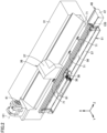
- Fig. 1 is a perspective view illustrating a machine tool according to a first embodiment of the present invention.
- a machine tool 100 according to the present embodiment is an NC (Numerically Control) machine tool in which various operations for machining a workpiece are automated by a computer via numerical control.
- the machine tool 100 is a composite machine capable of performing a turning operation by using a fixed tool and a milling operation by using a rotating tool.
- an axis which is parallel to the left-right direction (width direction) of the machine tool 100 and extends in the horizontal direction is referred to as a "Z axis”
- an axis which is parallel to the front-rear direction (depth direction) of the machine tool 100 and extends in the horizontal direction is referred to as a "Y axis”
- an axis which extends in the vertical direction is referred to as an "X axis”.
- the rightward direction is referred to as a "+Z axis direction”
- the leftward direction is referred to as a "-Z axis direction”.
- the forward direction of the page is referred to as a " +Y axis direction " and the backward direction thereof is referred to as a "-Y axis direction”.
- the +Y axis direction corresponds to the machine front direction.
- the upward direction is referred to as "+X axis direction”
- the downward direction is referred to as "-X axis direction”.
- the X axis, the Y axis, and the Z axis are orthogonal to each other.
- the machine tool 100 includes a cover body 21.
- the cover body 21 defines a machining area 110, and forms an outer appearance of the machine tool 100.
- the machining area 110 is a space where a workpiece is machined, and is substantially sealed so as to prevent foreign matters such as chips or cutting oil from flying to the outside of the machining area 110 during the machining of the workpiece.
- the cover body 21 includes a first door 22 and a second door 23 as doors, a side cover 27, and a magazine cover 26.
- the cover body 21 is provided with openings that make the machining area 110 open toward the +Y axis direction (the machine front direction) and the +X axis direction (the upward direction).
- Each of the first door 22 and the second door 23 is disposed in an opening provided in the cover body 21.
- the side cover 27 and the magazine cover 26 are provided on both sides of the opening provided in the cover body 21 in the Z axis direction.
- a work spindle (an opposing work spindle) for rotating the workpiece, a tailstock for supporting a rotation center of the workpiece, and the like are housed inside the side cover 27.
- a magazine or the like for storing a plurality of tools to be used for machining a workpiece is housed inside the magazine cover 26.
- the first door 22 and the second door 23 are slidable between a closed position where the opening provided in the cover body 21 is closed and an open position where the opening provided in the cover body 21 is opened.
- the first door 22 and the second door 23 are slidable in the Z axis direction. When the first door 22 and the second door 23 are slid to the open position, the first door 22 and the second door 23 overlap the side cover 27 in the Y axis direction.
- the first door 22 and the second door 23 may be manual doors that are slid manually, or may be automatic doors that are slid by an actuator such as a cylinder or a motor.
- Fig. 2 is a perspective view partially illustrating an internal structure of the machine tool of Fig. 1 .
- Fig. 3 is a side view illustrating the machine tool of Fig. 2 .
- the machine tool 100 further includes a bed 31, a work spindle 41, and a tool rest 36.
- the bed 31 is a base member for supporting the work spindle 41, the tool rest 36, a tool spindle (not shown) and the like, and is disposed on a floor FL of a factory or the like.
- the bed 31 has an elongated shape (a rectangular shape), the short direction of which is identical to the Y axis direction and the longitudinal direction of which is identical to the Z axis direction.
- the bed 31 is made of metal such as cast iron.
- the work spindle 41 is configured to hold a workpiece.
- the work spindle 41 has chuck claws 42 (see Fig. 3 ) configured to detachably hold the workpiece.
- the work spindle 41 is mainly provided to rotate the workpiece during a turning operation by using a fixed tool.
- the work spindle 41 is provided so as to be rotatable about a rotation center axis 121 (a second axis) parallel to the machine left-right direction (the Z axis direction).
- the work spindle 41 is fixed to the bed 31.
- the opposing work spindle arranged inside the side cover 27 is arranged opposite to the work spindle 41 in the Z axis direction.
- the tool rest 36 is configured to hold a plurality of tools.
- the tool rest 36 has a socalled turret type, and is radially mounted with a plurality of tools to perform a turning index operation.
- the tool rest 36 includes a turning member (not shown) and a tool rest base 37.
- the turning member is rotatable about a rotation center axis parallel to the Z axis.
- Tool holders for holding tools are mounted at positions spaced apart from each other in the circumferential direction of the rotation center axis.
- the tool rest base 37 supports the turning member.
- the tool rest 36 is disposed on the bed 31.
- the tool rest 36 is provided between the work spindle 41 and the opposing work spindle (not shown) in the Z axis direction.
- the tool rest 36 is slidable at least in the Z axis direction by various kinds of feed mechanisms, guide mechanisms, servo motors, and the like.
- the machine tool 100 further includes a coolant tank 46.
- the coolant tank 46 is disposed on the floor FL.
- the coolant tank 46 is disposed side by side with the bed 31 in the machine front-rear direction (the Y axis direction).
- the coolant tank 46 is provided in front of the bed 31 in the machine front direction.
- the coolant tank 46 is disposed opposite to the bed 31 in the Y axis direction.
- the coolant tank 46 is configured to store coolant to be used for machining a workpiece in the machining area 110.
- the coolant tank 46 includes a tank body 47 and a plurality of tires 48.
- the tank body 47 has an elongated shape, the longitudinal direction of which is identical to the Z axis direction (the machine left-right direction).
- the tank body 47 has a rectangular shape, the short direction of which is identical to the Y axis direction (the machine front-rear direction) and the longitudinal direction of which is identical to the Z axis direction (the machine left-right direction).
- the plurality of tires 48 are attached to the tank body 47.
- the plurality of tires 48 are spaced apart from each other and attached to a bottom portion of the tank body 47.
- the coolant tank 46 is provided at a position lower than the work spindle 41 and the tool rest 36.
- the coolant tank 46 is provided at a position partially overlapping the tool rest 36 in a top view.
- the machine tool 100 further includes a wire/pipe housing box 51, a wire/pipe 38, a cable bear (registered trademark) 61, and a foot stool 76.
- the wire/pipe housing box 51 is provided side by side with the coolant tank 46 in the machine front-rear direction (Y axis direction).
- the wire/pipe housing box 51 is provided in front of the coolant tank 46 in the machine front direction.
- the wire/pipe housing box 51 is disposed opposite to the coolant tank 46 in the Y axis direction.
- the wire/pipe housing box 51 forms an internal space 57.
- the wire/pipe housing box 51 has an elongated shape, the longitudinal direction of which is identical to the Z axis direction.
- the range in which the wire/pipe housing box 51 extends in the Z axis direction includes a sliding range of the tool rest 36 in the Z axis direction.
- the wire/pipe housing box 51 has an upper surface 56.
- the upper surface 56 is a horizontal surface.
- the upper surface 56 faces upward (the +X axis direction).
- the upper surface 56 extends in a band shape, the longitudinal direction of which is identical to the machine left-right direction (the Z axis direction).
- the upper surface 56 is disposed immediately below the first door 22 and the second door 23 when they are slid to the closed position.
- the upper surface 56 forms a scaffold for the operator at a position higher than the floor FL.
- the upper surface 56 is disposed at a position lower than the rotation center axis 121 of the work spindle 41 and higher than the coolant tank 46.
- the wire/pipe housing box 51 further includes an opposing member 55.
- the opposing member 55 is disposed opposite to the coolant tank 46 in the Y axis direction.
- the opposing member 55 faces toward the -Y axis direction.
- the wire/pipe 38 which is at least one of a wire and a pipe, is housed in the internal space 57.
- the wire/pipe 38 extends between the tool rest 36 (the tool rest base 37) and the wire/pipe housing box 51.
- the wire/pipe 38 includes at least one of an electrical wire, an air pipe, a lubricating oil pipe, and a hydraulic pipe.
- the wire/pipe 38 is drawn out from the tool rest 36 (the tool rest base 37) in the +Y axis direction.
- the wire/pipe 38 is bent toward the -X axis direction (the downward direction) and guided into the internal space 57.
- the wire/pipe 38 is arranged along the Z axis direction in the inner space 57.
- the cable bear 61 is housed in the internal space 57.
- the wire/pipe 38 is inserted through the cable bear 61 in the inner space 57.
- One end of the cable bear 61 is connected to the tool rest 36 (the tool rest base 37).
- the cable bear 61 can be stroked in the Z axis direction along with the sliding of the tool rest 36 in the Z axis direction.
- the foot stool 76 is disposed on the floor FL.
- the foot stool 76 is provided side by side with the wire/pipe housing box 51 in the machine front-rear direction (the Y axis direction).
- the foot stool 76 is provided in front of the wire/pipe housing box 51 in the machine front direction.
- the foot stool 76 is provided opposite to the wire/pipe housing box 51 in the Y axis direction.
- the foot stool 76 forms a scaffold for the operator at a position higher than the floor FL.
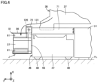
- Figs. 4 and 5 are side views for explaining the operation of the wire/pipe housing box.
- Fig. 4 illustrates the machine tool enclosed by a two-dot chain line IV in Fig. 3 .
- the machine tool 100 further includes a support arm 71.
- the support arm 71 can support the wire/pipe housing box 51 retracted from a first position J (the position illustrated in Figs. 2 to 4 ) in front of the coolant tank 46 in the machine front direction to a second position K higher than the coolant tank 46.
- the support arm 71 extends in an arm shape in the Y axis direction.
- the support arm 71 extends from the bed 31 in the machine front direction, and the wire/pipe housing box 51 is supported at a distal end of the support arm 71.
- the support arm 71 is provided above the coolant tank 46.
- the support arm 71 is made of metal.
- the support arm 71 is fastened to the bed 31 using a bolt or the like.
- the support arm 71 may be integrated with the bed 31.
- the machine tool 100 includes a plurality of support arms 71.
- the plurality of support arms 71 are arranged at intervals in the Z axis direction.
- the wire/pipe housing box 51 is connected to the support arm 71 so as to be movable between the first position J and the second position K.
- the wire/pipe housing box 51 is connected to the support arm 71 so as to be rotatable about a rotation center axis 126 (the first axis) extending in the machine left-right direction (the Z axis direction).
- the support arm 71 has a connection member 72.
- the connection member 72 is provided at an end portion of the support arm 71 in the +Y axis direction.
- the wire/pipe housing box 51 is connected to the connection member 72 so as to be rotatable about the rotation center axis 126.
- the rotation center axis 126 is disposed at a position higher than the coolant tank 46.
- the rotation center axis 126 is provided in front of the coolant tank 46 in the machine front direction.
- the wire/pipe housing box 51 rotates by 90° around the rotation center axis 126 between the first position J and the second position K.
- the upper surface 56 faces the -Y axis direction.
- the upper surface 56 is disposed opposite to the tool rest 36 in the Y axis direction.
- the opposing member 55 is disposed opposite to the floor FL in the Z axis direction (the vertical direction).
- the opposing member 55 corresponds to a lowermost portion of the wire/pipe housing box 51 positioned at the lowest height among the wire/pipe housing box 51.
- the opposing member 55 is positioned higher than the coolant tank 46.
- a space 141 is provided between the floor FL and the wire/pipe housing box 51 (the opposing member 55).
- the space 141 is opened toward the machine front direction when the foot stool 76 is removed from the floor FL.
- the machine tool 100 further includes a stopper 81 (a restriction member).
- the stopper 81 restricts the rotation motion of the wire/pipe housing box 51 from the second position K to the first position J.
- the stopper 81 has a pole shape extending in the vertical direction.
- the stopper 81 is interposed between the floor FL and the wire/pipe housing box 51.
- the stopper 81 is provided at a position away from the rotation center axis 126 in the radial direction of the rotation center axis 126.
- the stopper 81 is provided at a position shifted from the coolant tank 46 in the Z axis direction.
- the stopper 81 restricts the rotation motion of the wire/pipe housing box 51 from the second position K toward the first position J by using the weight of the wire/pipe housing box 51.
- the restriction member of the present invention is not limited to the stopper 81 described above, and may be a latch structure provided around the rotation center axis 126 and configured to allow the rotation motion of the wire/pipe housing box 51 from the first position J toward the second position K, and to restrict the rotation motion of the wire/pipe housing box 51 from the second position K toward the first position J.
- the motion of the wire/pipe housing box 51 between the first position J and the second position K is not limited to the rotation motion, and may be, for example, a vertical linear motion.
- the wire/pipe housing box 51 may be supported by a linear guide that guides the wire/pipe housing box 51 in the vertical direction.
- the coolant tank 46 is required to be pulled out from the position in front of the bed 31 in the machine front direction so as to clean the inside of the tank body 47 or to supply coolant to the tank body 47.
- the coolant tank 46 has an elongated shape, the longitudinal direction of which is identical to the axial direction (the machine left-right direction) of the rotation center axis 121 of the work spindle 41, it is necessary to secure a substantially large space on a lateral side of the machine tool 100 so as to pull out the coolant tank 46 in the machine left-right direction.
- the machine tool 100 by retracting the wire/pipe housing box 51 from the first position J in front of the coolant tank 46 to the second position K higher than the coolant tank 46, it is possible to easily pull out the coolant tank 46 through the space 141 to the machine front position, which makes it possible to improve the workability of the coolant tank 46 during maintenance.
- the wire/pipe housing box 51 is connected to the support arm 71 so as to be movable between the first position J and the second position K.
- the wire/pipe housing box 51 is connected to the support arm 71 so as to be rotatable about the rotation center axis 126 extending in the machine left-right direction. According to this configuration, since it is easy to move the wire/pipe housing box 51 between the first position J and the second position K, it is possible to further improve the workability of the coolant tank 46 during maintenance.
- the rotation center axis 126 is disposed at a position higher than the coolant tank 46.
- the wire/pipe housing box 51 is provided with a stopper 81 that restricts the rotation motion of the wire/pipe housing box 51 from the second position K toward the first position J. With this configuration, it is possible to prevent the wire/pipe housing box 51 from being unintentionally rotated from the second position K toward the first position J, which makes it possible to perform the operation of drawing out the coolant tank 46 safely.
- Fig. 6 is a side view illustrating a machine tool according to a comparative example.
- Fig. 6 corresponds to Fig. 3 .
- a wire/pipe housing box 251 is supported by a support arm 271 at a position in front of the tool rest 36 in the machine front direction.
- a space 146 for drawing out the coolant tank 46 is provided between the floor FL and the wire/pipe housing box 251.
- the upper surface 56 of the wire/pipe housing box 51 provided in front of the coolant tank 46 in the machine front direction can be used as a step surface that forms a scaffold for an operator.
- the operator is it possible to bring the operator closer to the workpiece held by the work spindle 41, and it is possible to place the operator's hand at a suitable height with respect to the workpiece held by the work spindle 41.
- the machine tool 100 according to the present embodiment includes a coolant tank 46 provided in front of a bed 31 in a machine front direction, a wire/pipe housing box 51 which serves as a structure provided at a first position J in front of the coolant tank 46 in the machine front direction, and a support arm 71 which serves as a support capable of supporting the wire/pipe housing box 51 retracted from the first position J to a second position K higher the coolant tank 46.
- the machine tool 100 of the first embodiment of the present invention configured as described above, by retracting the wire/pipe housing box 51 from the first position J in front of the coolant tank 46 in the machine front direction to the second position K higher than the coolant tank 46, it is possible to easily access the coolant tank 46 from the machine front direction.
- the machine tool according to the present invention is not limited to a composite machine, and may be, for example, a lathe, a vertical machining center or a horizontal machining center, or an AM/SM hybrid machine capable of performing AM (Additive Manufacturing) machining on a workpiece and performing SM (Subtractive Manufacturing) machining on a workpiece.
- Figs. 7 and 8 are side views illustrating a machine tool according to a second embodiment of the present invention.
- the machine tool according to the present embodiment basically has the same configuration as the machine tool 100 according to the first embodiment.
- the description of the same components will not be repeated.
- the machine tool includes a coolant tank 46 provided in front of the bed 31 in the machine front direction, a foot stool 76 serving as a structure provided at a first position J in front of the coolant tank 46 in the machine front direction, and a plurality of support poles 91 serving as a support member capable of supporting the foot stool 76 retracted from a first position J to a second position K higher than the coolant tank 46.
- the foot stool 76 is disposed on the floor FL in front of the coolant tank 46 in the machine front direction.
- the foot stool 76 is disposed opposite to the coolant tank 46 in the Y axis direction.
- the support pole 91 has a column shape extending in the vertical direction. A lower end of the support pole 91 is connected to the floor FL.
- the support pole 91 is provided with a locking member 93.
- the locking member 93 is provided at an upper end of the support pole 91.
- the locking member 93 is configured to lock a convex member 77 to be described later.
- the locking member 93 has a key shape capable of receiving the convex member 77 from below.
- the support pole 91 is provided at a position opposite to the foot stool 76 in the Z axis direction.
- the plurality of support poles 91 are provided at positions apart from each other in the Y axis direction and the Z axis direction.
- the foot stool 76 is provided with a plurality of convex members 77.
- the convex member 77 has a convex shape protruding in the Z axis direction.
- the convex member 77 is provided at a position immediately above the floor FL where the foot stool 76 is disposed.
- the plurality of convex members 77 are provided in correspondence relationship to the plurality of locking members 93, respectively.
- the plurality of convex members 77 are provided at equal pitches with the plurality of locking members 93 in the Y axis direction and the Z axis direction.
- the foot stool 76 is lifted upward from the floor FL.
- the plurality of convex members 77 are respectively locked by the plurality of locking members 93.
- the foot stool 76 is supported by the plurality of support poles 91 upward from the floor FL.
- a space 142 for drawing out the coolant tank 46 to the front side of the machine is formed between the floor FL and the foot stool 76.
- the present invention is applied to a machine tool including a coolant tank.
Landscapes
- Engineering & Computer Science (AREA)
- Mechanical Engineering (AREA)
- Machine Tool Units (AREA)
Abstract
Description
- The present invention relates to a machine tool.
- For example,
Japanese Patent Laying-Open No. 2-30401 - PTL 1:
Japanese Patent Laying-Open No. 2-30401 - As disclosed in PTL 1, there is known a machine tool in which a chip housing box (a coolant tank) is provided in front of a base (a bed) in the machine front direction. In such a machine tool, a structure such as a box configured to house pipes or wires, or a foot stool that forms a scaffold for an operator may be provided in front of the coolant tank in the machine front direction. In this case, the access to the coolant tank by the operator from the machine front direction is impeded by the structure such as the box or the foot stool.
- The present invention has been accomplished in view of the aforementioned problems, and an object thereof is to provide a machine tool that enables an easy access to a coolant tank from a machine front direction.
- A machine tool according to the present invention includes a coolant tank provided in front of a bed in a machine front direction, a structure provided at a first position in front of the coolant tank in the machine front direction, and a support capable of supporting the structure retracted from the first position to a second position higher than the coolant tank.
- Note that the "machine front direction" refers to a horizontal direction from a machining area of the machine tool toward a side where an operator stands to access the machining area of the machine tool.
- According to the machine tool configured as described above, the structure retracted from the first position to the second position is supported by the support, whereby the access to the coolant tank from the machine front direction is enabled.
- In an aspect, the structure is connected to the support so as to be operable between the first position and the second position.
- According to the machine tool configured as described above, it is possible to easily move the structure between the first position and the second position.
- In an aspect, the structure is connected to the support so as to be rotatable about a first axis extending in a machine left-right direction.
- The "machine left-right direction" refers to a horizontal direction orthogonal to the machine front direction.
- According to the machine tool configured as described above, it is possible to further easily move the structure between the first position and the second position.
- In an aspect, the first axis is disposed at a position higher than the coolant tank.
- According to the machine tool configured as described above, it is possible to easily achieve a configuration to retract the structure to the second position higher than the coolant tank.
- In an aspect, the machine tool further includes a restriction member that restricts the motion of the structure from the second position to the first position.
- According to the machine tool configured as described above, it is possible to prevent the structure from being unintentionally moved from the second position to the first position.
- In an aspect, the structure has an upper surface, the upper surface extends into a band shape, the longitudinal direction of which is identical to the machine left-right direction, and the upper surface is a horizontal surface when the structure is positioned at the first position.
- According to the machine tool configured as described above, when the upper surface of the structure is used as a step surface that forms a scaffold for an operator, the structure retracted from the first position to the second position is supported by the support, whereby the access to the coolant tank from the machine front direction is enabled.
- In an aspect, the machine tool further includes a work spindle that rotates a workpiece about a second axis extending in the machine left-right direction. The upper surface is disposed at a position lower than the second axis and higher than the coolant tank when the structure is positioned at the first position.
- According to the machine tool configured as described above, when the upper surface of the structure is used as a step surface that forms a scaffold for the operator, the operator's hand can be placed at a favorable height with respect to the workpiece held by the work spindle.
- In an aspect, the structure is formed with an internal space. The machine tool includes at least one of a wire and a pipe housed in the internal space.
- According to the machine tool configured as described above, when the internal space of the structure is used as a space for housing the wires and/or the pipes, the structure retracted from the first position to the second position is supported by the support, whereby the access to the coolant tank from the machine front direction is enabled.
- In an aspect, the coolant tank includes a tank body that has an elongated shape, the longitudinal direction of which is identical to the machine left-right direction in a top view, and is configured to store coolant, and a tire attached to the tank body.
- According to the machine tool configured as described above, by retracting the structure from the first position to the second position, it is possible to pull the coolant tank in the machine front direction.
- As described above, according to the present invention, it is possible to provide a machine tool that enables an easy access to the coolant tank from the machine front direction.
-
-
Fig. 1 is a perspective view illustrating a machine tool according to a first embodiment of the present invention; -
Fig. 2 is a perspective view partially illustrating an internal structure of the machine tool ofFig. 1 ; -
Fig. 3 is a side view illustrating the machine tool ofFig. 2 ; -
Fig. 4 is a side view for explaining the operation of a wire/pipe housing box; -
Fig. 5 is another side view for explaining the operation of the wire/pipe housing box; -
Fig. 6 is a side view illustrating a machine tool according to a comparative example; -
Fig. 7 is a side view illustrating a machine tool according to a second embodiment of the present invention; and -
Fig. 8 is another side view illustrating the machine tool according to the second embodiment of the present invention. - Embodiments of the present invention will be described with reference to the drawings. In the following drawings, the same or corresponding members are denoted by the same reference numerals.
-
Fig. 1 is a perspective view illustrating a machine tool according to a first embodiment of the present invention. With reference toFig. 1 , amachine tool 100 according to the present embodiment is an NC (Numerically Control) machine tool in which various operations for machining a workpiece are automated by a computer via numerical control. Themachine tool 100 is a composite machine capable of performing a turning operation by using a fixed tool and a milling operation by using a rotating tool. - In the present specification, an axis which is parallel to the left-right direction (width direction) of the
machine tool 100 and extends in the horizontal direction is referred to as a "Z axis", an axis which is parallel to the front-rear direction (depth direction) of themachine tool 100 and extends in the horizontal direction is referred to as a "Y axis", and an axis which extends in the vertical direction is referred to as an "X axis". InFig. 1 , the rightward direction is referred to as a "+Z axis direction", and the leftward direction is referred to as a "-Z axis direction". InFig. 1 , the forward direction of the page is referred to as a " +Y axis direction " and the backward direction thereof is referred to as a "-Y axis direction". The +Y axis direction corresponds to the machine front direction. InFig. 1 , the upward direction is referred to as "+X axis direction", and the downward direction is referred to as "-X axis direction". The X axis, the Y axis, and the Z axis are orthogonal to each other. - The
machine tool 100 includes acover body 21. Thecover body 21 defines amachining area 110, and forms an outer appearance of themachine tool 100. Themachining area 110 is a space where a workpiece is machined, and is substantially sealed so as to prevent foreign matters such as chips or cutting oil from flying to the outside of themachining area 110 during the machining of the workpiece. - The
cover body 21 includes afirst door 22 and asecond door 23 as doors, aside cover 27, and amagazine cover 26. - The
cover body 21 is provided with openings that make themachining area 110 open toward the +Y axis direction (the machine front direction) and the +X axis direction (the upward direction). Each of thefirst door 22 and thesecond door 23 is disposed in an opening provided in thecover body 21. Theside cover 27 and themagazine cover 26 are provided on both sides of the opening provided in thecover body 21 in the Z axis direction. A work spindle (an opposing work spindle) for rotating the workpiece, a tailstock for supporting a rotation center of the workpiece, and the like are housed inside theside cover 27. A magazine or the like for storing a plurality of tools to be used for machining a workpiece is housed inside themagazine cover 26. - The
first door 22 and thesecond door 23 are slidable between a closed position where the opening provided in thecover body 21 is closed and an open position where the opening provided in thecover body 21 is opened. Thefirst door 22 and thesecond door 23 are slidable in the Z axis direction. When thefirst door 22 and thesecond door 23 are slid to the open position, thefirst door 22 and thesecond door 23 overlap theside cover 27 in the Y axis direction. - The
first door 22 and thesecond door 23 may be manual doors that are slid manually, or may be automatic doors that are slid by an actuator such as a cylinder or a motor. -
Fig. 2 is a perspective view partially illustrating an internal structure of the machine tool ofFig. 1 .Fig. 3 is a side view illustrating the machine tool ofFig. 2 . With reference toFigs. 1 to 3 , themachine tool 100 further includes abed 31, awork spindle 41, and atool rest 36. - The
bed 31 is a base member for supporting thework spindle 41, thetool rest 36, a tool spindle (not shown) and the like, and is disposed on a floor FL of a factory or the like. - In a top view, the
bed 31 has an elongated shape (a rectangular shape), the short direction of which is identical to the Y axis direction and the longitudinal direction of which is identical to the Z axis direction. Thebed 31 is made of metal such as cast iron. - The
work spindle 41 is configured to hold a workpiece. Thework spindle 41 has chuck claws 42 (seeFig. 3 ) configured to detachably hold the workpiece. Thework spindle 41 is mainly provided to rotate the workpiece during a turning operation by using a fixed tool. Thework spindle 41 is provided so as to be rotatable about a rotation center axis 121 (a second axis) parallel to the machine left-right direction (the Z axis direction). Thework spindle 41 is fixed to thebed 31. - The opposing work spindle arranged inside the
side cover 27 is arranged opposite to thework spindle 41 in the Z axis direction. - The
tool rest 36 is configured to hold a plurality of tools. Thetool rest 36 has a socalled turret type, and is radially mounted with a plurality of tools to perform a turning index operation. Thetool rest 36 includes a turning member (not shown) and atool rest base 37. The turning member is rotatable about a rotation center axis parallel to the Z axis. Tool holders for holding tools are mounted at positions spaced apart from each other in the circumferential direction of the rotation center axis. Thetool rest base 37 supports the turning member. - The
tool rest 36 is disposed on thebed 31. Thetool rest 36 is provided between thework spindle 41 and the opposing work spindle (not shown) in the Z axis direction. Thetool rest 36 is slidable at least in the Z axis direction by various kinds of feed mechanisms, guide mechanisms, servo motors, and the like. - The
machine tool 100 further includes acoolant tank 46. Thecoolant tank 46 is disposed on the floor FL. Thecoolant tank 46 is disposed side by side with thebed 31 in the machine front-rear direction (the Y axis direction). Thecoolant tank 46 is provided in front of thebed 31 in the machine front direction. Thecoolant tank 46 is disposed opposite to thebed 31 in the Y axis direction. - The
coolant tank 46 is configured to store coolant to be used for machining a workpiece in themachining area 110. - The
coolant tank 46 includes atank body 47 and a plurality oftires 48. In a top view, thetank body 47 has an elongated shape, the longitudinal direction of which is identical to the Z axis direction (the machine left-right direction). In the top view, thetank body 47 has a rectangular shape, the short direction of which is identical to the Y axis direction (the machine front-rear direction) and the longitudinal direction of which is identical to the Z axis direction (the machine left-right direction). The plurality oftires 48 are attached to thetank body 47. The plurality oftires 48 are spaced apart from each other and attached to a bottom portion of thetank body 47. - The
coolant tank 46 is provided at a position lower than thework spindle 41 and thetool rest 36. Thecoolant tank 46 is provided at a position partially overlapping thetool rest 36 in a top view. - The
machine tool 100 further includes a wire/pipe housing box 51, a wire/pipe 38, a cable bear (registered trademark) 61, and afoot stool 76. - The wire/
pipe housing box 51 is provided side by side with thecoolant tank 46 in the machine front-rear direction (Y axis direction). The wire/pipe housing box 51 is provided in front of thecoolant tank 46 in the machine front direction. The wire/pipe housing box 51 is disposed opposite to thecoolant tank 46 in the Y axis direction. - The wire/
pipe housing box 51 forms aninternal space 57. The wire/pipe housing box 51 has an elongated shape, the longitudinal direction of which is identical to the Z axis direction. The range in which the wire/pipe housing box 51 extends in the Z axis direction includes a sliding range of thetool rest 36 in the Z axis direction. - The wire/
pipe housing box 51 has anupper surface 56. Theupper surface 56 is a horizontal surface. Theupper surface 56 faces upward (the +X axis direction). Theupper surface 56 extends in a band shape, the longitudinal direction of which is identical to the machine left-right direction (the Z axis direction). As illustrated inFig. 1 , theupper surface 56 is disposed immediately below thefirst door 22 and thesecond door 23 when they are slid to the closed position. Theupper surface 56 forms a scaffold for the operator at a position higher than the floor FL. - The
upper surface 56 is disposed at a position lower than therotation center axis 121 of thework spindle 41 and higher than thecoolant tank 46. - The wire/
pipe housing box 51 further includes an opposingmember 55. The opposingmember 55 is disposed opposite to thecoolant tank 46 in the Y axis direction. The opposingmember 55 faces toward the -Y axis direction. - The wire/
pipe 38, which is at least one of a wire and a pipe, is housed in theinternal space 57. The wire/pipe 38 extends between the tool rest 36 (the tool rest base 37) and the wire/pipe housing box 51. The wire/pipe 38 includes at least one of an electrical wire, an air pipe, a lubricating oil pipe, and a hydraulic pipe. - The wire/
pipe 38 is drawn out from the tool rest 36 (the tool rest base 37) in the +Y axis direction. The wire/pipe 38 is bent toward the -X axis direction (the downward direction) and guided into theinternal space 57. The wire/pipe 38 is arranged along the Z axis direction in theinner space 57. - The
cable bear 61 is housed in theinternal space 57. The wire/pipe 38 is inserted through thecable bear 61 in theinner space 57. One end of thecable bear 61 is connected to the tool rest 36 (the tool rest base 37). Thecable bear 61 can be stroked in the Z axis direction along with the sliding of thetool rest 36 in the Z axis direction. - The
foot stool 76 is disposed on the floor FL. Thefoot stool 76 is provided side by side with the wire/pipe housing box 51 in the machine front-rear direction (the Y axis direction). Thefoot stool 76 is provided in front of the wire/pipe housing box 51 in the machine front direction. Thefoot stool 76 is provided opposite to the wire/pipe housing box 51 in the Y axis direction. Thefoot stool 76 forms a scaffold for the operator at a position higher than the floor FL. -
Figs. 4 and5 are side views for explaining the operation of the wire/pipe housing box.Fig. 4 illustrates the machine tool enclosed by a two-dot chain line IV inFig. 3 . - With reference to
Figs. 2 to 5 , themachine tool 100 further includes asupport arm 71. As illustrated inFig. 5 , thesupport arm 71 can support the wire/pipe housing box 51 retracted from a first position J (the position illustrated inFigs. 2 to 4 ) in front of thecoolant tank 46 in the machine front direction to a second position K higher than thecoolant tank 46. - The
support arm 71 extends in an arm shape in the Y axis direction. Thesupport arm 71 extends from thebed 31 in the machine front direction, and the wire/pipe housing box 51 is supported at a distal end of thesupport arm 71. Thesupport arm 71 is provided above thecoolant tank 46. Thesupport arm 71 is made of metal. Thesupport arm 71 is fastened to thebed 31 using a bolt or the like. Thesupport arm 71 may be integrated with thebed 31. - As illustrated in
Fig. 2 , themachine tool 100 includes a plurality ofsupport arms 71. The plurality ofsupport arms 71 are arranged at intervals in the Z axis direction. - With reference to
Figs. 4 and5 , the wire/pipe housing box 51 is connected to thesupport arm 71 so as to be movable between the first position J and the second position K. The wire/pipe housing box 51 is connected to thesupport arm 71 so as to be rotatable about a rotation center axis 126 (the first axis) extending in the machine left-right direction (the Z axis direction). - The
support arm 71 has aconnection member 72. Theconnection member 72 is provided at an end portion of thesupport arm 71 in the +Y axis direction. The wire/pipe housing box 51 is connected to theconnection member 72 so as to be rotatable about therotation center axis 126. Therotation center axis 126 is disposed at a position higher than thecoolant tank 46. Therotation center axis 126 is provided in front of thecoolant tank 46 in the machine front direction. - The wire/
pipe housing box 51 rotates by 90° around therotation center axis 126 between the first position J and the second position K. - As illustrated in
Fig. 5 , when the wire/pipe housing box 51 is arranged at the second position K, theupper surface 56 faces the -Y axis direction. Theupper surface 56 is disposed opposite to thetool rest 36 in the Y axis direction. The opposingmember 55 is disposed opposite to the floor FL in the Z axis direction (the vertical direction). The opposingmember 55 corresponds to a lowermost portion of the wire/pipe housing box 51 positioned at the lowest height among the wire/pipe housing box 51. The opposingmember 55 is positioned higher than thecoolant tank 46. - A
space 141 is provided between the floor FL and the wire/pipe housing box 51 (the opposing member 55). Thespace 141 is opened toward the machine front direction when thefoot stool 76 is removed from the floor FL. - The
machine tool 100 further includes a stopper 81 (a restriction member). Thestopper 81 restricts the rotation motion of the wire/pipe housing box 51 from the second position K to the first position J. - The
stopper 81 has a pole shape extending in the vertical direction. Thestopper 81 is interposed between the floor FL and the wire/pipe housing box 51. Thestopper 81 is provided at a position away from therotation center axis 126 in the radial direction of therotation center axis 126. When themachine tool 100 is viewed in the Y axis direction, thestopper 81 is provided at a position shifted from thecoolant tank 46 in the Z axis direction. Thestopper 81 restricts the rotation motion of the wire/pipe housing box 51 from the second position K toward the first position J by using the weight of the wire/pipe housing box 51. - The restriction member of the present invention is not limited to the
stopper 81 described above, and may be a latch structure provided around therotation center axis 126 and configured to allow the rotation motion of the wire/pipe housing box 51 from the first position J toward the second position K, and to restrict the rotation motion of the wire/pipe housing box 51 from the second position K toward the first position J. - The motion of the wire/
pipe housing box 51 between the first position J and the second position K is not limited to the rotation motion, and may be, for example, a vertical linear motion. In this case, the wire/pipe housing box 51 may be supported by a linear guide that guides the wire/pipe housing box 51 in the vertical direction. - In some cases, the
coolant tank 46 is required to be pulled out from the position in front of thebed 31 in the machine front direction so as to clean the inside of thetank body 47 or to supply coolant to thetank body 47. However, when thecoolant tank 46 has an elongated shape, the longitudinal direction of which is identical to the axial direction (the machine left-right direction) of therotation center axis 121 of thework spindle 41, it is necessary to secure a substantially large space on a lateral side of themachine tool 100 so as to pull out thecoolant tank 46 in the machine left-right direction. - On the contrary, in the
machine tool 100 according to the present embodiment, by retracting the wire/pipe housing box 51 from the first position J in front of thecoolant tank 46 to the second position K higher than thecoolant tank 46, it is possible to easily pull out thecoolant tank 46 through thespace 141 to the machine front position, which makes it possible to improve the workability of thecoolant tank 46 during maintenance. - The wire/
pipe housing box 51 is connected to thesupport arm 71 so as to be movable between the first position J and the second position K. The wire/pipe housing box 51 is connected to thesupport arm 71 so as to be rotatable about therotation center axis 126 extending in the machine left-right direction. According to this configuration, since it is easy to move the wire/pipe housing box 51 between the first position J and the second position K, it is possible to further improve the workability of thecoolant tank 46 during maintenance. - The
rotation center axis 126 is disposed at a position higher than thecoolant tank 46. With this configuration, when the wire/pipe housing box 51 is rotated about therotation center axis 126, thespace 141 for drawing out thecoolant tank 46 can be easily provided below the wire/pipe housing box 51. - Further, as illustrated in
Figs. 4 and5 , since theinternal space 57 in which the wire/pipe 38 is housed is only moved in the circumferential direction of therotation center axis 126 by the rotation motion of the wire/pipe housing box 51, it is possible to prevent a large change in the wring route of the wire/pipe 38 from thetool rest 36 toward the internal space 57 (the wiring route of the wire/pipe 38 from thetool rest 36 to theinner space 57 is indicated by anarrow 131 inFig. 4 and anarrow 132 inFig. 5 ). - Further, the wire/
pipe housing box 51 is provided with astopper 81 that restricts the rotation motion of the wire/pipe housing box 51 from the second position K toward the first position J. With this configuration, it is possible to prevent the wire/pipe housing box 51 from being unintentionally rotated from the second position K toward the first position J, which makes it possible to perform the operation of drawing out thecoolant tank 46 safely. -
Fig. 6 is a side view illustrating a machine tool according to a comparative example.Fig. 6 corresponds toFig. 3 . With reference toFig. 6 , in this comparative example, a wire/pipe housing box 251 is supported by asupport arm 271 at a position in front of thetool rest 36 in the machine front direction. Aspace 146 for drawing out thecoolant tank 46 is provided between the floor FL and the wire/pipe housing box 251. - In such a comparative example, when an operator stands on the
upper surface 256 of the wire/pipe housing box 251 and attempts to access themachining area 110, the position of the operator's hand is too high as compared with the position of the workpiece held by thework spindle 41. Further, when the operator stands on thefoot stool 76 and attempts to access themachining area 110, the position of the operator's hand is away from the position of the workpiece held by thework spindle 41 in the Y axis direction. In any case, it is concerned that the operator is forced to take an unusual posture to work, which impairs the workability of thework spindle 41 or the workpiece held by thework spindle 41. - On the contrary, in the present embodiment, with reference to
Fig. 3 , theupper surface 56 of the wire/pipe housing box 51 provided in front of thecoolant tank 46 in the machine front direction can be used as a step surface that forms a scaffold for an operator. Thereby, is it possible to bring the operator closer to the workpiece held by thework spindle 41, and it is possible to place the operator's hand at a suitable height with respect to the workpiece held by thework spindle 41. - Hereinafter, the
machine tool 100 according to the first embodiment of the present invention described above will be summarized. Themachine tool 100 according to the present embodiment includes acoolant tank 46 provided in front of abed 31 in a machine front direction, a wire/pipe housing box 51 which serves as a structure provided at a first position J in front of thecoolant tank 46 in the machine front direction, and asupport arm 71 which serves as a support capable of supporting the wire/pipe housing box 51 retracted from the first position J to a second position K higher thecoolant tank 46. - According to the
machine tool 100 of the first embodiment of the present invention configured as described above, by retracting the wire/pipe housing box 51 from the first position J in front of thecoolant tank 46 in the machine front direction to the second position K higher than thecoolant tank 46, it is possible to easily access thecoolant tank 46 from the machine front direction. - The machine tool according to the present invention is not limited to a composite machine, and may be, for example, a lathe, a vertical machining center or a horizontal machining center, or an AM/SM hybrid machine capable of performing AM (Additive Manufacturing) machining on a workpiece and performing SM (Subtractive Manufacturing) machining on a workpiece.
-
Figs. 7 and8 are side views illustrating a machine tool according to a second embodiment of the present invention. The machine tool according to the present embodiment basically has the same configuration as themachine tool 100 according to the first embodiment. Hereinafter, the description of the same components will not be repeated. - With reference to
Figs. 7 and8 , the machine tool according to the present embodiment includes acoolant tank 46 provided in front of thebed 31 in the machine front direction, afoot stool 76 serving as a structure provided at a first position J in front of thecoolant tank 46 in the machine front direction, and a plurality ofsupport poles 91 serving as a support member capable of supporting thefoot stool 76 retracted from a first position J to a second position K higher than thecoolant tank 46. - In the present embodiment, the
foot stool 76 is disposed on the floor FL in front of thecoolant tank 46 in the machine front direction. Thefoot stool 76 is disposed opposite to thecoolant tank 46 in the Y axis direction. - The
support pole 91 has a column shape extending in the vertical direction. A lower end of thesupport pole 91 is connected to the floor FL. Thesupport pole 91 is provided with a lockingmember 93. The lockingmember 93 is provided at an upper end of thesupport pole 91. The lockingmember 93 is configured to lock aconvex member 77 to be described later. The lockingmember 93 has a key shape capable of receiving theconvex member 77 from below. Thesupport pole 91 is provided at a position opposite to thefoot stool 76 in the Z axis direction. The plurality ofsupport poles 91 are provided at positions apart from each other in the Y axis direction and the Z axis direction. - The
foot stool 76 is provided with a plurality ofconvex members 77. Theconvex member 77 has a convex shape protruding in the Z axis direction. Theconvex member 77 is provided at a position immediately above the floor FL where thefoot stool 76 is disposed. The plurality ofconvex members 77 are provided in correspondence relationship to the plurality of lockingmembers 93, respectively. The plurality ofconvex members 77 are provided at equal pitches with the plurality of lockingmembers 93 in the Y axis direction and the Z axis direction. - As illustrated in
Fig. 8 , thefoot stool 76 is lifted upward from the floor FL. The plurality ofconvex members 77 are respectively locked by the plurality of lockingmembers 93. Thereby, thefoot stool 76 is supported by the plurality ofsupport poles 91 upward from the floor FL. Thus, aspace 142 for drawing out thecoolant tank 46 to the front side of the machine is formed between the floor FL and thefoot stool 76. - According to the second embodiment of the present invention configured as described above, it is possible for the machine tool to obtain the same effect as that described in the first embodiment.
- It should be understood that the embodiments disclosed herein have been presented for the purpose of illustration and description but not limited in all aspects. It is intended that the scope of the present invention is not limited to the description above but defined by the scope of the claims and encompasses all modifications equivalent in meaning and scope to the claims.
- The present invention is applied to a machine tool including a coolant tank.
- 21: cover body; 22: first door; 23: second door; 26: magazine cover; 27: side cover; 31: bed; 36: tool rest; 37: tool rest base; 38: pipe; 41: work spindle; 42: chuck claw; 46: coolant tank; 47: tank body; 48: tire; 51: pipe housing box; 55: opposing member; 56, 256: upper surface; 57: internal space; 61: cable bear; 71, 71: support arm; 72: connection member; 76: foot stool; 77: convex member; 81: stopper; 91: support pole; 93: locking member; 100: machine tool; 110: machining area; 121: rotation center axis; 126: rotation center axis; 141, 142, 146: space; J: first position; K: second position
Claims (9)
- A machine tool comprising:a coolant tank provided in front of a bed in a machine front direction;a structure provided at a first position in front of the coolant tank in the machine front direction; anda support capable of supporting the structure retracted from the first position to a second position higher than the coolant tank.
- The machine tool according to claim 1, wherein
the structure is connected to the support so as to be operable between the first position and the second position. - The machine tool according to claim 2, wherein
the structure is connected to the support so as to be rotatable about a first axis extending in a machine left-right direction. - The machine tool according to claim 3, wherein
the first axis is disposed at a position higher than the coolant tank. - The machine tool according to any one of claims 2 to 4, wherein
the structure further includes a restriction member that restricts the motion of the structure from the second position to the first position. - The machine tool according to any one of claims 1 to 5, whereinthe structure has an upper surface,the upper surface extends into a band shape, the longitudinal direction of which is identical to the machine left-right direction, and the upper surface is a horizontal surface when the structure is positioned at the first position.
- The machine tool according to claim 6, further comprising a work spindle that rotates a workpiece about a second axis extending in the machine left-right direction, wherein
the upper surface is disposed at a position lower than the second axis and higher than the coolant tank when the structure is positioned at the first position. - The machine tool according to any one of claims 1 to 7, whereinthe structure is formed with an internal space,the machine tool further includes at least one of a wire and a pipe housed in the internal space.
- The machine tool according to any one of claims 1 to 8, wherein
the coolant tank includes a tank body that has an elongated shape, the longitudinal direction of which is identical to the machine left-right direction in a top view, and is configured to store coolant, and a tire which is attached to the tank body.
Applications Claiming Priority (1)
| Application Number | Priority Date | Filing Date | Title |
|---|---|---|---|
| PCT/JP2020/019224 WO2021229739A1 (en) | 2020-05-14 | 2020-05-14 | Machine tool |
Publications (3)
| Publication Number | Publication Date |
|---|---|
| EP4137265A1 true EP4137265A1 (en) | 2023-02-22 |
| EP4137265A4 EP4137265A4 (en) | 2023-06-14 |
| EP4137265B1 EP4137265B1 (en) | 2026-04-29 |
Family
ID=78525489
Family Applications (1)
| Application Number | Title | Priority Date | Filing Date |
|---|---|---|---|
| EP20935158.4A Active EP4137265B1 (en) | 2020-05-14 | 2020-05-14 | Machine tool |
Country Status (5)
| Country | Link |
|---|---|
| US (1) | US20230173626A1 (en) |
| EP (1) | EP4137265B1 (en) |
| JP (1) | JP7299417B2 (en) |
| CN (1) | CN115605316A (en) |
| WO (1) | WO2021229739A1 (en) |
Families Citing this family (1)
| Publication number | Priority date | Publication date | Assignee | Title |
|---|---|---|---|---|
| TWI812405B (en) * | 2022-08-16 | 2023-08-11 | 東佑達自動化科技股份有限公司 | slide device |
Family Cites Families (33)
| Publication number | Priority date | Publication date | Assignee | Title |
|---|---|---|---|---|
| US2793972A (en) * | 1954-05-24 | 1957-05-28 | Goodyear Aircraft Corp | Method of making metal-faced laminates |
| GB873979A (en) * | 1957-04-24 | 1961-08-02 | Newall Eng | Improvements in or relating to machine tools embodying automatically-operable slides |
| JPH0683921B2 (en) | 1988-04-19 | 1994-10-26 | 中村留精密工業株式会社 | 2-spindle opposed type CNC lathe |
| JP2830450B2 (en) * | 1990-10-29 | 1998-12-02 | オ−クマ株式会社 | Work step |
| JPH0539843U (en) * | 1991-10-25 | 1993-05-28 | オークマ株式会社 | Machine tool chip discharge device |
| JP3543100B2 (en) * | 2000-03-09 | 2004-07-14 | 榎本ビーエー株式会社 | Filtration device for chip conveyor |
| JP2003251578A (en) * | 2002-02-27 | 2003-09-09 | Howa Mach Ltd | Folding step |
| JP3952160B2 (en) * | 2002-03-22 | 2007-08-01 | ブラザー工業株式会社 | Cutting fluid filtration device |
| DE10242929A1 (en) | 2002-09-16 | 2004-03-18 | Trützschler GmbH & Co KG | Machine enclosure, especially for card, has overhead structure cantilevered from one end to give completely free access to sides and other end |
| JP4186057B2 (en) * | 2003-05-30 | 2008-11-26 | ブラザー工業株式会社 | Cutting fluid recovery device for machine tools |
| US7387478B2 (en) * | 2004-08-27 | 2008-06-17 | Ford Motor Company | Machining system with integrated chip hopper |
| JP4558436B2 (en) | 2004-10-12 | 2010-10-06 | 株式会社牧野フライス製作所 | Vertical machining center |
| DE102006039618A1 (en) | 2006-08-24 | 2008-03-20 | Sirona Dental Systems Gmbh | Processing machine, in particular for the production of dental prostheses or models thereof |
| JP4958300B2 (en) * | 2007-11-08 | 2012-06-20 | 株式会社森精機製作所 | Machine Tools |
| KR20100061884A (en) * | 2008-12-01 | 2010-06-10 | 두산인프라코어 주식회사 | Collant recovery device of machine tool |
| JP2010247328A (en) | 2010-06-28 | 2010-11-04 | Mori Seiki Co Ltd | Machine Tools |
| JP2014008537A (en) | 2012-06-27 | 2014-01-20 | Tsubakimoto Meifuran Kk | Chip separation discharger |
| JP5599493B1 (en) * | 2013-07-04 | 2014-10-01 | 株式会社牧野フライス製作所 | Machine Tools |
| CN103722184B (en) * | 2013-12-26 | 2015-12-02 | 常州克迈特数控科技有限公司 | New-type lathe bed cisten mechanism |
| CN104842169B (en) * | 2015-03-18 | 2017-03-01 | 绍兴大丸精密机械有限公司 | A kind of drilling-tapping center machine |
| JP6650290B2 (en) * | 2016-02-17 | 2020-02-19 | Dmg森精機株式会社 | Machine Tools |
| CN206717529U (en) * | 2017-04-21 | 2017-12-08 | 南通鑫圣数控机床有限公司 | A kind of milling machine coolant retracting device |
| JP2019025599A (en) * | 2017-07-31 | 2019-02-21 | ファナック株式会社 | Machine tool |
| CN107243777A (en) | 2017-08-10 | 2017-10-13 | 成都益睿信科技有限公司 | A kind of numerical control machining center noise reduction protective cover |
| JP2020005571A (en) | 2018-07-09 | 2020-01-16 | 三菱マヒンドラ農機株式会社 | Chemical spraying device in transplanting machine |
| CN108655755B (en) | 2018-08-03 | 2021-01-19 | 深圳市诚创数控设备有限公司 | Digit control machine tool that clean degree is high |
| JP7144238B2 (en) | 2018-08-24 | 2022-09-29 | Dgshape株式会社 | cutting machine |
| CN208841034U (en) * | 2018-09-17 | 2019-05-10 | 成都天马铁路轴承有限公司 | A kind of machine tool chip removal device |
| CN209831076U (en) * | 2019-03-26 | 2019-12-24 | 常州市武进安圩液压件制造有限公司 | Deep hole boring machine with coolant liquid separation filter equipment |
| JP7417017B2 (en) * | 2019-06-21 | 2024-01-18 | スター精密株式会社 | Machine Tools |
| JP7496332B2 (en) * | 2021-03-31 | 2024-06-06 | オークマ株式会社 | Cutting fluid tank for machine tools |
| EP4331750A4 (en) * | 2021-04-30 | 2025-02-26 | DMG Mori Co., Ltd. | BAR FEEDING DEVICE AND MACHINE TOOL |
| CN114178908A (en) * | 2021-12-29 | 2022-03-15 | 厦门台匠精密机械有限公司 | Multi-axis linkage engraving machine |
-
2020
- 2020-05-14 WO PCT/JP2020/019224 patent/WO2021229739A1/en not_active Ceased
- 2020-05-14 EP EP20935158.4A patent/EP4137265B1/en active Active
- 2020-05-14 US US17/924,544 patent/US20230173626A1/en active Pending
- 2020-05-14 CN CN202080100902.6A patent/CN115605316A/en active Pending
- 2020-05-14 JP JP2022522425A patent/JP7299417B2/en active Active
Also Published As
| Publication number | Publication date |
|---|---|
| EP4137265A4 (en) | 2023-06-14 |
| CN115605316A (en) | 2023-01-13 |
| JP7299417B2 (en) | 2023-06-27 |
| WO2021229739A1 (en) | 2021-11-18 |
| EP4137265B1 (en) | 2026-04-29 |
| JPWO2021229739A1 (en) | 2021-11-18 |
| US20230173626A1 (en) | 2023-06-08 |
Similar Documents
| Publication | Publication Date | Title |
|---|---|---|
| EP2679338B1 (en) | Machining center | |
| AU657852B2 (en) | Machining centre constructed from assemblies | |
| US9901987B2 (en) | Machine tool | |
| US5300006A (en) | Automatic tool changer | |
| EP1116548A2 (en) | A machine tool having a vertical main spindle and a method of making the same | |
| EP4137265B1 (en) | Machine tool | |
| EP0108187A1 (en) | Multiple axis slant bed machine | |
| KR102057727B1 (en) | Machining center with multi-spindle | |
| WO2021215001A1 (en) | Processing machine | |
| CN108714788B (en) | A dual-spindle turning and milling compound CNC machine tool | |
| CN208543193U (en) | A kind of double main shaft turnning and milling combined numerically controlled machines | |
| JP5646833B2 (en) | Lathe with automatic tool changer | |
| US20230173568A1 (en) | Clamp device and processing machine | |
| WO2023162116A1 (en) | Tool magazine and machine tool | |
| KR102120583B1 (en) | Side processing apparatus for production | |
| CN218051530U (en) | Mechanical feeding execution device of numerical control boring machine | |
| CN208600724U (en) | A dual-spindle structure for CNC machine tools | |
| CN223699414U (en) | Vertical deep hole drill machine tool | |
| EP4613423A1 (en) | Machining system | |
| CN219945394U (en) | Telescopic tool magazine | |
| CN211465486U (en) | Numerical control machining center | |
| JP7372458B2 (en) | processing machinery | |
| CN208600728U (en) | A double turret structure for CNC machine tools | |
| EP0203035B1 (en) | System for guiding a movable upright of a machine tool which improves the working accuracy of the machine | |
| JP2010058172A (en) | Cnc lathe for long-sized material |
Legal Events
| Date | Code | Title | Description |
|---|---|---|---|
| STAA | Information on the status of an ep patent application or granted ep patent |
Free format text: STATUS: THE INTERNATIONAL PUBLICATION HAS BEEN MADE |
|
| PUAI | Public reference made under article 153(3) epc to a published international application that has entered the european phase |
Free format text: ORIGINAL CODE: 0009012 |
|
| STAA | Information on the status of an ep patent application or granted ep patent |
Free format text: STATUS: REQUEST FOR EXAMINATION WAS MADE |
|
| 17P | Request for examination filed |
Effective date: 20221115 |
|
| AK | Designated contracting states |
Kind code of ref document: A1 Designated state(s): AL AT BE BG CH CY CZ DE DK EE ES FI FR GB GR HR HU IE IS IT LI LT LU LV MC MK MT NL NO PL PT RO RS SE SI SK SM TR |
|
| A4 | Supplementary search report drawn up and despatched |
Effective date: 20230516 |
|
| RIC1 | Information provided on ipc code assigned before grant |
Ipc: B23Q 11/00 20060101ALI20230511BHEP Ipc: B23Q 1/01 20060101ALI20230511BHEP Ipc: B23Q 1/00 20060101AFI20230511BHEP |
|
| DAV | Request for validation of the european patent (deleted) | ||
| DAX | Request for extension of the european patent (deleted) | ||
| GRAP | Despatch of communication of intention to grant a patent |
Free format text: ORIGINAL CODE: EPIDOSNIGR1 |
|
| STAA | Information on the status of an ep patent application or granted ep patent |
Free format text: STATUS: GRANT OF PATENT IS INTENDED |
|
| INTG | Intention to grant announced |
Effective date: 20251128 |
|
| GRAS | Grant fee paid |
Free format text: ORIGINAL CODE: EPIDOSNIGR3 |
|
| GRAA | (expected) grant |
Free format text: ORIGINAL CODE: 0009210 |
|
| STAA | Information on the status of an ep patent application or granted ep patent |
Free format text: STATUS: THE PATENT HAS BEEN GRANTED |
|
| AK | Designated contracting states |
Kind code of ref document: B1 Designated state(s): AL AT BE BG CH CY CZ DE DK EE ES FI FR GB GR HR HU IE IS IT LI LT LU LV MC MK MT NL NO PL PT RO RS SE SI SK SM TR |
|
| REG | Reference to a national code |
Ref country code: CH Ref legal event code: F10 Free format text: ST27 STATUS EVENT CODE: U-0-0-F10-F00 (AS PROVIDED BY THE NATIONAL OFFICE) Effective date: 20260429 Ref country code: GB Ref legal event code: FG4D |