EP4137019A1 - Base de robot de cuisine, module de préparation et robot de cuisine - Google Patents
Base de robot de cuisine, module de préparation et robot de cuisine Download PDFInfo
- Publication number
- EP4137019A1 EP4137019A1 EP21192449.3A EP21192449A EP4137019A1 EP 4137019 A1 EP4137019 A1 EP 4137019A1 EP 21192449 A EP21192449 A EP 21192449A EP 4137019 A1 EP4137019 A1 EP 4137019A1
- Authority
- EP
- European Patent Office
- Prior art keywords
- locking
- kitchen appliance
- preparation module
- locking element
- appliance base
- Prior art date
- Legal status (The legal status is an assumption and is not a legal conclusion. Google has not performed a legal analysis and makes no representation as to the accuracy of the status listed.)
- Pending
Links
Images


Classifications
-
- A—HUMAN NECESSITIES
- A47—FURNITURE; DOMESTIC ARTICLES OR APPLIANCES; COFFEE MILLS; SPICE MILLS; SUCTION CLEANERS IN GENERAL
- A47J—KITCHEN EQUIPMENT; COFFEE MILLS; SPICE MILLS; APPARATUS FOR MAKING BEVERAGES
- A47J43/00—Implements for preparing or holding food, not provided for in other groups of this subclass
- A47J43/04—Machines for domestic use not covered elsewhere, e.g. for grinding, mixing, stirring, kneading, emulsifying, whipping or beating foodstuffs, e.g. power-driven
- A47J43/07—Parts or details, e.g. mixing tools, whipping tools
- A47J43/0727—Mixing bowls
-
- A—HUMAN NECESSITIES
- A47—FURNITURE; DOMESTIC ARTICLES OR APPLIANCES; COFFEE MILLS; SPICE MILLS; SUCTION CLEANERS IN GENERAL
- A47J—KITCHEN EQUIPMENT; COFFEE MILLS; SPICE MILLS; APPARATUS FOR MAKING BEVERAGES
- A47J43/00—Implements for preparing or holding food, not provided for in other groups of this subclass
- A47J43/04—Machines for domestic use not covered elsewhere, e.g. for grinding, mixing, stirring, kneading, emulsifying, whipping or beating foodstuffs, e.g. power-driven
- A47J43/07—Parts or details, e.g. mixing tools, whipping tools
- A47J43/08—Driving mechanisms
- A47J43/085—Driving mechanisms for machines with tools driven from the lower side
-
- A—HUMAN NECESSITIES
- A47—FURNITURE; DOMESTIC ARTICLES OR APPLIANCES; COFFEE MILLS; SPICE MILLS; SUCTION CLEANERS IN GENERAL
- A47J—KITCHEN EQUIPMENT; COFFEE MILLS; SPICE MILLS; APPARATUS FOR MAKING BEVERAGES
- A47J43/00—Implements for preparing or holding food, not provided for in other groups of this subclass
- A47J43/04—Machines for domestic use not covered elsewhere, e.g. for grinding, mixing, stirring, kneading, emulsifying, whipping or beating foodstuffs, e.g. power-driven
- A47J43/046—Machines for domestic use not covered elsewhere, e.g. for grinding, mixing, stirring, kneading, emulsifying, whipping or beating foodstuffs, e.g. power-driven with tools driven from the bottom side
-
- A—HUMAN NECESSITIES
- A47—FURNITURE; DOMESTIC ARTICLES OR APPLIANCES; COFFEE MILLS; SPICE MILLS; SUCTION CLEANERS IN GENERAL
- A47J—KITCHEN EQUIPMENT; COFFEE MILLS; SPICE MILLS; APPARATUS FOR MAKING BEVERAGES
- A47J43/00—Implements for preparing or holding food, not provided for in other groups of this subclass
- A47J43/04—Machines for domestic use not covered elsewhere, e.g. for grinding, mixing, stirring, kneading, emulsifying, whipping or beating foodstuffs, e.g. power-driven
- A47J43/07—Parts or details, e.g. mixing tools, whipping tools
- A47J43/075—Safety devices
- A47J43/0761—Safety devices for machines with tools driven from the lower side
- A47J43/0766—Safety devices for machines with tools driven from the lower side activated by the proper positioning of the mixing bowl
Definitions
- the invention relates to a kitchen appliance base with at least one receiving area for at least one preparation module.
- the invention further relates to a preparation module for arranging in a receiving area of a kitchen appliance base and a kitchen appliance that comprises a kitchen appliance base and at least one preparation module.
- the kitchen appliance base has at least one locking means for mechanically locking the preparation module to the kitchen appliance base.
- Kitchen appliances with a kitchen appliance base and a preparation module are known in the prior art in a large number of configurations. Such kitchen appliances are used for automatic, semi-automatic or manual preparation, e.g. B. crushing, grinding, pressing, stirring, cooking and / or keeping warm, especially food.
- the kitchen appliance usually has a kitchen appliance base that provides a receiving area for at least one preparation module.
- the receiving area often has at least one electrical interface in order to supply a preparation module placed in the receiving area with at least one working voltage, for example for a heating device, or to contact sensors, for example.
- At least one drive interface is provided in the receiving area, for example, the transmission of torque from a working unit, z. B. a motor, the kitchen appliance base is used, for example, on a tool arranged on the preparation module.
- the kitchen appliance base usually has a locking means to remove the preparation module after locking with the to prevent kitchen appliance base. Locking ensures a safe working process and in particular prevents the preparation module from being accidentally removed during a working process.
- the locking is often carried out manually in that a bayonet lock is formed between the preparation module and the kitchen appliance base, which is locked in that the preparation module is rotated by the user in the receiving area by a predetermined angle.
- the locking means have, for example, displaceable locking arms which are held on the base of the kitchen appliance approximately at the height of a lid of a preparation module.
- the latch arms are rotatable between a latched position and a release position.
- the invention is therefore based on the object of specifying a kitchen appliance base, a preparation module and a kitchen appliance with which automatic locking of different preparation modules on a kitchen appliance base is made possible.
- the locking means has at least one drive unit and at least one movably held locking element.
- the locking element is at least indirectly between at least one release position and at least one by the drive unit Locking position movable so that the preparation module can be locked to the kitchen appliance base and the lock can be released.
- a preparation module In the release position of the locking element, a preparation module can be arranged in at least two different orientations in the receiving area.
- “two different orientations” means that the preparation module can be arranged in at least two different orientations, in particular rotated relative to one another, in the one receiving area.
- An operating means of the preparation module is oriented to the right in a first orientation, for example, and to the left in a second orientation, for example.
- the brewing module is locked to the utensil base.
- the kitchen appliance base and a preparation module arranged in the receiving area are connected to one another, preferably in a form-fitting manner, preferably in the receiving area, so that the preparation module can no longer be removed from the receiving area.
- the preparation module is locked at least axially, so that at least a proportion of forces in a direction parallel to a central axis A can be transmitted via the locking element.
- the receiving area of the kitchen appliance base is set up and designed for connection to the preparation module.
- the preparation module is preferably accommodated at least partially in the accommodation area.
- the receiving area for the preparation vessel is preferably designed at least partially in terms of its shape to essentially correspond to a foot section of the preparation module, in particular in order to receive the preparation module at least partially in a form-fitting manner.
- the receiving area is designed in particular in such a way that a rotation of the preparation module relative to the base of the kitchen appliance is already prevented by the at least two defined orientations. In the two orientations relative to the kitchen appliance base, a positive fit that prevents rotation is already prevented when arranging the preparation module in the receiving area.
- the drive unit preferably has at least one drive means, in particular at least one rotating electric motor and/or at least one linear motor. Furthermore, the drive unit has at least one transmission means connected to the drive means, in particular at least one gear, for example a worm, spur and/or bevel gear, and/or a drive belt and/or a drive chain.
- the drive means is preferably connected to at least one gearbox.
- the transmission has a plurality of gear wheels.
- the drive unit is in particular directly or indirectly connected to the movably mounted locking element, so that the locking element can be moved by the drive unit at least between at least one release position and at least one locking position.
- the drive unit has at least one clutch device, for example at least one slip clutch.
- the clutch device is preferably designed and arranged in the drive unit in such a way that it is triggered when at least one threshold value for a force during a movement and/or a torque is exceeded in order to prevent damage to the drive unit and/or other components of the kitchen appliance base and/or the preparation module impede.
- the locking element is designed and set up in such a way that a preparation module can be arranged in the release position in at least two, preferably exactly two, different orientations, preferably in two orientations offset from one another by at least 90°, in particular by 180°, in the receiving area.
- the locking means is designed in such a way that locking can take place in each of the arrangements.
- the preparation module is divided into at least two, in particular exactly two, at least three, in particular exactly three, or at least four, in particular exactly four orientations can be arranged and locked in the receiving area.
- the locking element is moved in the direction of the locking position, so that locking, in particular an axial locking, of the preparation module with the kitchen appliance base is effected at the latest when the locking position is reached.
- the preparation module is locked in the receiving area with the kitchen appliance base.
- the movement of the locking element leads to at least one locking section of the locking element interacting with at least one locking counter-section of the preparation module in a form-fitting manner.
- the preparation module can consequently be locked to the kitchen appliance base by moving the locking element.
- At least two, in particular exactly two, at least three, in particular exactly three, or at least four, in particular exactly four, locking sections and/or locking counter sections are preferably provided.
- the locking sections and locking counter-sections are arranged such that a preparation module can be arranged in the release position of the locking element in at least two, preferably exactly two, different orientations, preferably in two orientations offset by at least 90°, in particular by 180°, in the receiving area.
- the locking sections and locking counter-sections are arranged in such a way that the preparation module can be arranged and locked in at least three, in particular exactly three, or at least four, in particular exactly four, alignments in the receiving area.
- the kitchen appliance base preferably has at least one housing on which the receiving area for receiving at least one preparation module is formed.
- the receiving area is preferably arranged essentially in a plane E, which is essentially parallel to a base of the Kitchen appliance base is formed with normal use.
- the kitchen appliance base preferably has at least one working unit with at least one electric motor, the torque of which can be transmitted via a drive interface in the receiving area.
- a torque is transmitted, for example, via a corresponding drive interface of a preparation module to a shaft or to a tool arranged in the preparation module, for example a stirring and/or chopping device.
- the kitchen appliance base has at least one weighing device for weighing food arranged in the preparation module and also has at least one mains connection for the voltage supply.
- the kitchen appliance base also has at least one electrical interface, for example.
- the electrical interface is designed for electrical contacting of a preparation module that can be arranged in the receiving area.
- the electrical interface is preferably arranged in the receiving area. In the state in which it is introduced into the receiving area, the electrical interface makes contact, in particular, with an electrical counter-interface on the preparation module.
- the kitchen appliance base also has, in particular, a control device.
- the drive unit is preferably controlled by the control device of the kitchen appliance base, in particular the control device causes a movement in the direction of the release position or the locking position.
- the control device preferably includes power electronics in order to operate at least one heating device, for example a preparation module, which is contacted at the electrical interface.
- the invention has the advantage over the prior art that different preparation modules can be automatically locked to the kitchen appliance base. Furthermore, the preparation modules can be placed in different orientations on the kitchen appliance base, so that, for example different requirements for left- and right-handers can be taken into account.
- the locking element can be rotated by means of the drive unit.
- the drive unit acts directly or indirectly on the locking element. It is advantageously provided that the drive unit interacts with a toothed strip of a drive lever, the drive lever being connected to the locking element in a form-fitting manner, in particular by two pins.
- the pins are in particular formed in one piece with the locking element and are arranged in corresponding recesses in the drive lever. A movement of the drive lever by the drive unit consequently directly causes a movement, in particular a rotation, of the locking element.
- the drive unit is preferably arranged in such a way that the locking element and/or the drive lever are driven from outside the respective axis of rotation.
- the locking element and/or the drive lever can preferably be rotated about an axis which also corresponds to the axis of rotation of a working unit, in particular a motor, for driving a tool, preferably within a preparation module.
- a shaft for transmitting a torque to a tool is preferably arranged centrally in the kitchen appliance base so that it is surrounded by the locking element and/or the drive lever.
- the drive lever and/or the locking element have a central recess.
- the drive lever is designed, for example, in the shape of a ring, a disk or as a segment of a circle.
- a plurality of spur gear stages are arranged, which bring about interaction with the locking element.
- a further embodiment provides that the locking element, in particular the two pins, at least partially passes through a base plate which is arranged in particular on the upper side of the kitchen appliance base.
- the locking element is preferably designed as a locking ring which is arranged on an upper side of the kitchen appliance base in the receiving area.
- the locking ring is preferably arranged between a surface of the kitchen appliance base and a contact carrier module arranged on the surface of the kitchen appliance base.
- the contact carrier module is preferably held stationary and rotationally fixed relative to the surface of the kitchen appliance base. The locking ring consequently moves relative to the top of the kitchen appliance base and to the contact carrier module.
- At least the section of the locking element that protrudes between the contact carrier module and the surface of the kitchen appliance base is ring-shaped.
- the locking element is movable in a locking plane.
- the locking plane is preferably aligned essentially parallel to a standing surface of the kitchen appliance base or a surface of the kitchen appliance base.
- the footprint is the footprint on which the kitchen appliance base is placed for normal use.
- the surface of the kitchen utensil base is the surface of the housing on which the receiving area is arranged and on which the preparation module is placed.
- the locking element is preferably arranged essentially between the upper side of the kitchen appliance base and the preparation module.
- the locking element acts directly together with the preparation module, for example, or the locking element acts indirectly Locking the brewing module to the utensil base.
- the locking element has at least one locking section, and that the locking section in the locking position of the preparation module arranged in the receiving area has at least interacts in a form-fitting locking manner with a locking counter-section of the preparation module.
- the locking section and the counter-locking section are arranged in such a way that the preparation module can be removed from the receiving area, in particular essentially in the direction of a central axis A.
- the locking element has at least two locking sections, which each interact in a form-fitting manner with an associated counter locking section of the preparation module.
- the at least two locking sections are arranged essentially opposite one another on a circumference of the locking element.
- the locking section has a hook-shaped or stepped cross-section or is hook-shaped or stepped, so that at least part of the locking section can be moved, in particular rotated, into positive interaction with a locking counter-section on a preparation module.
- the locking element consequently rotates into positive locking with the preparation module, in particular a foot region of the preparation module.
- the locking element has at least one Has driver contour.
- the driver contour is designed to interact with a driver counter-contour on a locking counter-ring on the preparation module.
- the driver contour on the locking element protrudes, for example, on the locking element.
- At least two driver contours are preferably provided on the locking element, which are arranged in particular opposite one another on a circumference.
- at least three, exactly three, at least four or exactly four driver contours and associated driver counter-contours are provided.
- the driver contours and the driver counter-contours are arranged in such a way that the preparation module can be arranged in the release position in at least two orientations in the receiving area.
- the driver contour is designed in such a way that it can interact in a form-fitting manner with a driver counter-contour on a counter-locking element, in particular a counter-locking ring, on the preparation module.
- a rotation of the locking element can be transferred to the counter-locking element on the preparation module by means of the driver contour.
- the driver contour is designed as a driver rib and/or the driver counter-contour is designed as a corresponding driver gap.
- the form-fitting joining of the driver contour and the driver counter-contour takes place by arranging the preparation module in the receiving area.
- the counter-locking element is rotatably mounted, in particular in a foot section of the preparation module. At least one locking section, in particular at least two locking sections, is formed on the locking counter-element.
- the counter locking element can be moved by the locking element between a release position and a locking position. When the locking element is in the locking position, the counter-locking element is also in the locking position. Is the locking element in the Release position, the locking counter-element is also in the release position.
- the locking section or the locking sections of the counter-locking element interact in a form-fitting manner with at least one locking contour on the upper side of the kitchen appliance base, as a result of which the preparation module is connected in a form-fitting manner to the kitchen appliance base.
- At least two, in particular exactly two, at least three, in particular exactly three, at least four, in particular exactly four, at least five, in particular exactly five, or at least six, in particular exactly six, locking contours are preferably provided on the upper side of the kitchen appliance base.
- Each locking contour preferably extends from an upper side of the kitchen appliance base, in particular essentially vertically upwards.
- the locking contour is or the locking contours are preferably hook-shaped, so that a respective locking section of the locking counter-element can rotate under the hook-shaped locking contours in order to lock a preparation module with the kitchen appliance base.
- the locking contours are preferably designed and set up in such a way that they define the receiving area of the kitchen appliance base.
- the locking contours have insertion bevels in order to position the preparation module in the receiving area.
- at least the locking mating ring has a number of recesses corresponding to the number of locking contours, in particular in a circumferential locking section, in order to enable the preparation module to be arranged on the kitchen appliance base.
- an electrical interface is arranged on the kitchen appliance base, in particular in the receiving area, and if the electrical interface has at least two power contacts and at least one auxiliary contact.
- the electrical interface is used to make contact with an electrical counter-interface on the preparation module.
- at least one of the power contacts and/or at least the auxiliary contact of the electrical interface preferably at least indirectly by means of the drive unit, moves from a rest position at least in the direction of a contact position the kitchen appliance base is movable.
- the electrical interface preferably has at least two, at least three or at least four power contacts.
- At least two, at least three or at least four power contacts and/or at least one, at least two, at least three, at least four, at least five, at least six, at least seven or at least eight auxiliary contacts are provided.
- the auxiliary contacts are arranged symmetrically on the kitchen appliance base in such a way that a preparation module can be arranged in at least two different orientations.
- auxiliary contact extends at least over part of a peripheral surface, in particular of a contact carrier module, in the receiving area.
- the auxiliary contacts are designed, for example, for measurement, control and/or regulation purposes. At least one auxiliary contact is preferably designed as a protective conductor and/or at least two auxiliary contacts are designed as signal contacts, in particular for at least one temperature sensor, preferably a thermocouple, of the preparation module and/or at least one auxiliary contact is designed as a cover contact and/or at least one auxiliary contact is designed for transmission formed by data and / or signals to the preparation module and / or is at least one auxiliary contact for the power supply of Components formed in a preparation module with non-critical voltages for a touch.
- the movement of the power contact or the power contacts and/or the auxiliary contact is controlled in such a way that the power contacts or the auxiliary contact are in a contact position when the locking element is in a locking position. Likewise, the power contacts and/or the auxiliary contact are in a rest position when the locking element is in a release position.
- the power contacts or the auxiliary contact are preferably moved from the rest position at least in the direction of the contact position during and/or after the preparation module has been introduced into the receiving area. It is therefore provided that a movement of the power contacts and/or the auxiliary contact already begins while a preparation module is being arranged in the receiving area and is completed after the introduction. It is also envisaged that the movement of the power contacts and/or the auxiliary contact only begins after the preparation module has been arranged in the receiving area.
- Locking and electrical contacting preferably take place at least partially or completely simultaneously, in particular under the action of the drive unit. It is also provided that the electrical contact is made at a different point in time than the mechanical locking of the preparation module with the kitchen appliance base, for example before the mechanical locking or after the mechanical locking. Provision is also made for the electrical contacting to take place at least partially simultaneously and at least partially before or after locking. For example, the auxiliary contacts before the mechanical interlock contacted and the power contacts at least partially simultaneously, fully simultaneously with the mechanical interlock, or the power contacts are contacted after the mechanical interlock.
- the locking element is moved at least partially simultaneously, in particular completely simultaneously, with the at least one power contact and/or at least with the auxiliary contact in order to lock a preparation module.
- the locking element is moved before or after the at least one power contact and/or at least the auxiliary contact in order to lock a preparation module.
- the drive unit is, for example, mechanically connected both to the locking element of the locking means and to the power contacts and/or the auxiliary contact, so that the drive unit brings about all movements automatically. It is preferably provided that all power contacts and/or all auxiliary contacts can be moved between a rest position and a contact position. It is also provided, for example, that the contact and rest positions for the power contacts and the auxiliary contacts are different.
- the power contacts are in contact with counter power contacts of the preparation module in the contact position.
- the auxiliary contact or the auxiliary contacts make contact with an auxiliary counter-contact or with a plurality of auxiliary counter-contacts of the preparation module.
- Electrical contacted does not mean the actual application of voltage or current, but merely the physical contact, which in principle enables current or signals to be conducted.
- the two power contacts are movable and can be contacted or are contacted with counter power contacts designed as contact blades.
- the auxiliary contact and the Auxiliary mating contact or the auxiliary contacts and the auxiliary mating contacts are each stationary, in particular designed as resilient contact clips.
- the power contacts are designed as the first interface type and the auxiliary contact or the auxiliary contacts are designed as the second interface type.
- the first and second interface types are designed differently.
- the movement of the power contact or the power contacts and/or the auxiliary contact or the auxiliary contacts takes place rotationally, translationally or as a combination thereof.
- the movement takes place, for example, radially, ie in a plane that is parallel to a footprint of the kitchen appliance base, for example, or axially, ie in a direction that is orthogonal to a footprint of the kitchen appliance base. It is also provided that the movement takes place in a direction that is inclined to the standing surface of the kitchen appliance base.
- At least one of the power mating contacts, preferably both power mating contacts, and/or at least the auxiliary mating contacts or the auxiliary mating contacts of the mating interface of the preparation module can be moved from a rest position at least in the direction of a contact position on the preparation module.
- the power counter-contact or the power counter-contacts or the auxiliary counter-contact are therefore movably held on the preparation module and, like the contacts of the electrical interface, are moved from a rest position at least in the direction of a contact position, preferably between a rest position and a contact position, moved.
- This exemplary embodiment has the advantage over the prior art that arranging the preparation module in the receiving area is simplified.
- the contact forces for the user are reduced because contact is made with at least one contact of the electrical interface, preferably all contacts, only after the preparation module has been arranged in the receiving area.
- the drive unit is, for example - as described above - arranged in the kitchen appliance base and is also used for locking and/or a further drive unit is additionally arranged in the preparation module and/or a movement of the drive unit of the kitchen appliance base is reflected in the state in which it is introduced into the receiving area on the counter power contacts or transfer the auxiliary mating contact.
- the drive unit is at least indirectly, in particular directly, mechanically connected to the power contacts, the auxiliary contact, the power mating contacts and/or the auxiliary mating contact, so that these are/is movable by the drive unit.
- the power contacts are preferably held in contact carriers, each contact carrier engaging with a drive projection in a link recess on the drive lever.
- the drive projections interact with the link recess in such a way that a rotation of the drive lever causes a translational movement of the contact carrier with the power contacts.
- the invention also relates to a preparation module, in particular for a kitchen appliance base according to one of the exemplary embodiments described above.
- the preparation module is designed to be arranged in a receiving area of a kitchen appliance base as described above.
- the preparation module preferably has, in particular in its foot section, at least one electrical mating interface--as described above--for contacting with a electrical interface of the kitchen appliance base.
- the preparation module is locked in particular in its foot section, in particular from below, to the kitchen appliance base, in particular to the receiving area of the kitchen appliance base.
- the preparation module has a movable, in particular rotatable, mounted locking counter-element.
- the counter-locking element is preferably designed as a counter-locking ring.
- the counter-locking element is mounted on a housing of the preparation module.
- the counter-locking element can be moved by the locking element of the kitchen appliance base—as described above—in the state in which it is arranged in the receiving area, at least between a locking position and a release position.
- the counter-locking element is designed in such a way that the locking element of the kitchen appliance base can positively engage in at least two positions of the counter-locking element, in particular on a circumference of the counter-locking element, for moving, in particular for rotating. This ensures that the preparation module can be applied to the kitchen appliance base or arranged in the receiving area in at least two different orientations.
- the counter-locking element has at least two counter-contours for driving, which can interact with at least one contour for driving on the locking element of the kitchen appliance base.
- the driver contours and/or the driver counter-contours preferably have insertion bevels for easier assembly. If the kitchen appliance base has only a single driver contour on the locking element, this can engage in one or the other driver counter-contour of the locking counter-element, depending on the orientation of the preparation module. If two carrier contours are formed on the locking element of the kitchen appliance base, these can each be inserted into both carrier counter-contours, alternately into Depending on the orientation of the preparation module, intervene. This applies to any number of driver contours and driver counter-contours.
- the locking element causes - while it itself moves from its release position to its locking position - a movement of the locking counter-element from a release position into a locking position, wherein in the locking position - as described above - a locking section of the locking counter-ring interacts in a form-fitting manner with locking contours on an upper side of the kitchen appliance base, whereby the brewing module is locked to the utensil base.
- the mating locking element is operatively connected to at least one mating power contact, in particular all mating power contacts, and/or at least the auxiliary mating contact, in particular all mating auxiliary contacts, such that a movement of the mating locking element into the locking position causes a movement of at least one mating power contact and/or moves at least the auxiliary mating contact from a rest position to a contact position on the preparation module.
- the locking element has at least one circumferential groove and the locking element is rotatably mounted on the preparation module, in particular in a foot section of the preparation module, by means of the groove. Provision is preferably made for a circumferential web on the preparation module to engage in the groove on the counter-locking element, so that the locking ring is mounted on the preparation module so that it can rotate but is stable and cannot tilt. High forces can be transmitted when the web engages in the circumferential groove.
- the preparation module there is at least one preparation space and the preparation space can be closed with at least one cover.
- the preparation module also has at least one lid locking device.
- the lid locking device is operatively connected to the counter-locking element, so that the lid locking device can be used to lock at least one lid that can be arranged on the preparation module, at least in the locking position of the counter-locking element.
- the counter locking element and the lid locking device are coupled in such a way that the lid is locked when the counter locking element is in its locking position and the lid is released when the counter locking element is in its release position.
- the counter locking element and the lid locking device are coupled or controlled in such a way that in a first step the preparation module is locked to the kitchen appliance base and then in a second step, in particular with a time delay or based on an input or action by a user, the lid is locked with the preparation module.
- This enables a user to remove the lid of the preparation module when the preparation module is locked to the kitchen appliance base, for example to bring in food.
- the lid locking device comprises means for locking the lid to the preparation module under the effect of the rotation of the counter-locking element.
- the cover locking device has, for example, a rotatable rod or a gear.
- a lid is locked with the preparation module—if present—at the same time.
- the preparation module preferably has at least one electrical heating device, in particular at least two electrical heating devices. Each electrical heating device is contacted via the electrical counter-interface.
- the preparation module has at least one tool, for example a grating tool, a stirring tool and/or a crushing tool. It is also provided that the tool is designed, for example, as a fruit and/or vegetable press or grater. It is envisaged that the functions of the aforementioned tools will be combined in one tool.
- the preparation module has at least one drive interface to transmit torque from a working unit, e.g. B. a motor, to transfer the kitchen appliance base to a tool arranged in the preparation module.
- a control device of the kitchen appliance controls, for example, at least partially automatically or automatically, a heating process of the preparation module or a process of preparing a meal.
- the control device are preferably also program sequences for the preparation of food, z. B. recipes, in particular semi-automatically or automatically controlled.
- the kitchen appliance base or the kitchen appliance for automatic, semi-automatic or manual preparation e.g. B. crushing, grinding, pressing, stirring, cooking and / or keeping warm, especially of food.
- the preparation module preferably has a preparation interior for accommodating food.
- the preparation module is designed, for example, as a preparation pot, in particular with at least one integrated heating device and at least one integrated stirring device. Foodstuffs can be heated with the heating device. Foodstuffs can be stirred and/or comminuted with the stirring device.
- the preparation module has at least one heating surface as a heating module, which can be heated with at least one heating device, and on which at least one vessel, in particular a pot or a wok or a pan, can be placed.
- the present invention also relates to a kitchen appliance which has at least one kitchen appliance base, in particular according to one of the exemplary embodiments described above, and at least one preparation module, in particular according to one of the exemplary embodiments described above.
- the kitchen appliance according to the invention is set up and designed in particular for the preparation of food.
- the kitchen appliance is preferably set up and designed in such a way that contact is made by moving the power contacts and locking takes place automatically after the preparation module has been introduced into the receiving area of the kitchen appliance base.
- the kitchen appliance is preferably set up and designed in such a way that contact is made by moving the power contacts and locking takes place automatically after the preparation module has been introduced into the receiving area of the kitchen appliance base.
- FIG 1 shows an embodiment of a kitchen appliance 1, having a kitchen appliance base 2 and a preparation module 3.
- the preparation module 3 is arranged in a receiving area 4 of the kitchen appliance base 2 .
- the kitchen appliance base 2 has an operating and display device 5.
- a top 7 of the Kitchen appliance base 2 is essentially flat and designed parallel to a standing surface of kitchen appliance base 2 in normal use.
- FIG. 2 shows an exemplary embodiment of a kitchen appliance base 2 without a preparation module 3 attached, in a perspective view.
- an electrical interface 8 which has two power contacts 8a and a total of eight auxiliary contacts 8b.
- a locking means 9 for mechanically locking a - in 1 illustrated - preparation module 3 formed.
- the locking means 9 has at least one - for example in the 6 , 10 and 15 shown - drive unit 10 and a movably held locking element 11.
- the locking element 11 is in accordance with this embodiment 1 designed as a locking ring.
- the locking element 11 is rotatable, in particular about a central axis A, held on the base 2 of the kitchen appliance.
- the locking element 11 is movable below the auxiliary contacts 8b.
- the drive unit 10 is arranged outside of the drive axis A.
- the locking element 11 is held in a locking plane E, which is essentially parallel to the upper side 7 of the kitchen appliance base 2 .
- the locking element 11 can be moved by the drive unit 10 between at least one locking position and one release position.
- a preparation module 3 can be arranged in at least two different alignments in the receiving area 4 .
- the preparation module 3 is locked to the kitchen appliance base 4 .
- two oppositely arranged locking sections 12 are provided on the locking element 11 .
- the locking sections 12 have a substantially stepped cross section. When the locking element 11 rotates, these stepped locking sections 12 are brought into positive engagement with a mating locking section formed on the preparation module 3, so that the preparation module 3 is positively locked to the kitchen appliance base 2 and can no longer be removed from the receiving area 4 .
- the kitchen appliance base 2 can be put into operation together with the preparation module 3, namely the kitchen appliance 1.
- both the power contacts 8a and the auxiliary contacts 8b with associated mating power contacts--not shown--and associated auxiliary mating contacts--not shown--of the preparation module 3 are contacted, so that the preparation module 3 is electrically contacted.
- the power contacts 8a are used, for example, to operate a heating device arranged in the preparation module 3 .
- the auxiliary contacts 8b serve, for example, to contact a protective conductor and/or two auxiliary contacts 8b serve to transmit signals for at least one temperature sensor arranged in the preparation module 3, in particular at least one thermocouple, and/or at least one auxiliary contact 8b serves to contact a cover contact of the preparation module 3.
- the power contacts 8a and the auxiliary contacts 8b are arranged on a contact carrier module 13.
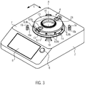
- FIG. 3 shows an alternative embodiment of a kitchen appliance base 2 in a perspective view.
- the receiving area 4 is in turn provided on an upper side 7 of the kitchen appliance base 2 .
- the locking means 9 with the rotatable locking element 11 is arranged in the receiving area 4 .
- the locking element 11 is also arranged in this exemplary embodiment between the upper side 7 of the kitchen appliance base 2 and a contact carrier module 13 arranged on the kitchen appliance base 2 .
- the power contacts 8a and the auxiliary contacts 8b of the electrical interface 8 are arranged on the contact carrier module 13 .
- the contact carrier module 13 is essentially disc-shaped with a central recess 24 .
- the power contacts 8a are on a top and the auxiliary contacts 8b are arranged on a lateral peripheral surface.
- the locking element 11, which is designed here as a locking ring, is held in a rotatable manner.
- two driver contours 14 Arranged on the locking element 11 are two driver contours 14 which are arranged opposite one another on the circumference of the locking element 11 and are designed here as driver ribs.
- the driver contours 14 engage in, for example in Figures 8 and 9 as in 11 shown, driver counter-contours 15, here in the form of driver columns, a.
- the driver contour 14 interacts with the driver counter-contour 15 in a form-fitting manner, so that a rotational movement, in particular about the axis A, can be transmitted.
- the driver contours 14 and driver contours 15 are arranged in such a way that the preparation module 3 can be arranged in two different orientations in the receiving area 4 .
- the locking element 11 is driven by the drive unit 10, with the locking element 11 having a locking counter-element 16 (see FIG Figures 8, 9 , 10 and 14 ) between an in 8 shown release position and an in 9 locking position shown moved.
- the counter locking element 16, according to Figure 8, Figure 9 , 10 and 11 is designed as a locking mating ring, has a circumferential locking section 12 which is interrupted by recesses 17 .
- the recesses 17 are used so that the locking contours 18 provided on the upper side 7 of the kitchen appliance base 2 can engage behind the locking sections 12 in order to 9 locking position shown to interact positively with the locking sections 12.
- the locking sections 12 each have a locking surface 12a, according to the locked state 9 interacts positively with a counter-locking surface 18a.
- the locking contours 18 are essentially hook-shaped.
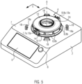
- FIGS. 4 and figure 5 show a further exemplary embodiment of a kitchen appliance base 2 in which a locking means 9 with a locking element 11 is arranged in the receiving area 4 .
- the locking element 11 is designed as a locking ring and - how to 3 described -, in particular about a central axis A, arranged rotatably.
- the locking element 11 is movable below the power contacts 8a and the auxiliary contacts 8b.
- the contact carrier module 13 is designed in such a way that the power contacts 8a are mounted on contact carriers 13a between an in 4 rest position shown, in which the contact carrier 13a have completely disappeared into the contact carrier module 13, and a contact position in figure 5 shown are movable.
- the contact carrier 13a with the power contacts 8a protrudes at least partially from the contact carrier module 13, so that these - with the preparation module 3 arranged in the receiving area 4 - with the counter power contacts 35a of the electrical counter interface 35 of the preparation module 3, shown by way of example in 12 , are contacted.
- the locking element 11 with an in 16 illustrated drive lever 21 in operative connection.
- the rotatable locking element 11 is arranged below the contact carrier module 13 .
- the drive lever 21 is arranged below the locking element 11 and is essentially ring-shaped.
- the drive lever 21 is positively connected to the locking element 11 .
- the drive lever 21 has a curved toothed strip 23 which is connected to the drive unit 10, in particular to a gear wheel 10b of the drive unit 10. A movement of the drive lever 21, which is caused by the drive unit 10, consequently causes an identical movement, here rotation, of the locking element 11, namely between a release position and a locking position.
- the drive lever 21 also has two link recesses 29 which are connected to the contact carriers 13a, in particular with Drive projections 36 of the contact carriers 13a, interact in such a way that the contact carriers 13a move from a rest position (see 4 ) into a contact position (see figure 5 ) can be moved. Provision is also made for the movements to take place at least partially simultaneously or with a time delay.
- the contact carrier 13a are automatically retracted into the contact carrier module 13 by the action of the drive lever 21 . This ensures that the power contacts 8a are stored in the contact carrier module 13 so that they cannot be touched when the preparation module 3 can be removed from the receiving area 4 . Movement between release position - see 4 - and a locking position - figure 5 - Is controlled by a control device of the kitchen appliance base 2, which controls the drive unit 10.
- the auxiliary contacts 8b are activated by placing the preparation module 3 with corresponding auxiliary counter-contacts 35b (see 12 ) of the preparation module 3 contacted.
- the locking element 11 again has driver contours 14 which interact with corresponding driver counter-contours 15 on the preparation module 3 .
- the preparation module 3 When assembled in a kitchen appliance base 2 according to 4 and figure 5 Consequently, the preparation module 3 is locked simultaneously and in particular automatically with the kitchen appliance base 2 and the power contacts 8a are electrically contacted with the mating power contacts 35a of the preparation module 3.
- This exemplary embodiment has the advantage that the forces for arranging the preparation module 3 in the receiving area 4 of the Kitchen appliance base 2 are significantly reduced, whereby the comfort for the user is increased.
- the preparation module 3 can be arranged in two different alignments in the receiving area 4 .
- the drive unit 10 has a motor 10a and a transmission 10c comprising a plurality of gear wheels 10b.
- the drive unit 10 is held on the base plate 19 .
- the locking element 11 shown separately, here a locking ring passes through the base plate 19 with two pins 20 approximately orthogonally.
- the drive pins 20 are according to 6 positively connected to a drive lever 21 by the drive pins 20 engage in associated recesses 22 in the drive lever 21.
- the drive lever 21 has according to 6 an arcuate toothed strip 23 which is connected to the gear wheel 10b, here a worm wheel, of the drive unit 10. If the gear wheel 10b of the drive unit 10 is rotated, the rack 23 moves, whereby the drive lever 21 and thus the locking element 11 on the other side of the base plate 19 from a release position into a locking position (see 9 ) or from a locking position to a release position (see 8 ) is moved.
- the contact carrier module 13 has according to 8 and 9 a central recess 24, which can be passed through by a drive interface--not shown--for transmitting a torque, for example to a tool in a preparation module 3.
- FIG 10 shows a section through a base plate 19 of a kitchen appliance base 2, in particular according to FIG 3 , with an attached preparation module 3, which is embodied here as a preparation vessel with a preparation interior 3a.
- the counter-locking element 16 here in the form of a counter-locking ring, has a circumferential groove 25 which interacts with an associated web 26 in a foot section 3b of the preparation module 3 such that the counter-locking element 16 on the preparation module 3 can be rotated.
- FIG 10 only the means for mechanically locking the preparation module 3 to the kitchen appliance base 2 are shown for illustration purposes.
- the arrangement of an electrical counter-interface 36 in particular similar to that in 12 or 13 shown, required.
- the rotation of the locking counter-element 16 is brought about by the interaction of the driver contours 14 of the locking element 11 with the driver counter-contours 15 on the locking counter-element 16 .
- the rotation of the locking element 11 is in turn effected by a transmission of torque from the drive lever 21, which in turn is moved by the drive unit 10 - see for example 6 .
- This design has the advantage over the prior art that the preparation module 3 can be reliably and automatically locked to the kitchen appliance base 2 with an extremely flat design.
- the central recess 24 can be passed through by a mechanical drive interface.
- FIG 11 shows an embodiment of a preparation module 3 in a partial perspective view.
- the preparation module 3 is essentially according to the embodiment of FIG 10 educated. Only the means for mechanically locking the preparation module 3 to the kitchen utensil base 2 are shown for illustration purposes. For the electrical contact, the arrangement of an electrical counter-interface 8, in particular similar to that in 11 or 14 shown, required.
- the recess 24 is of an arrangeable drive interface - not shown - penetrable, for example, the transmission of torque from a working unit, z. B. a motor, the kitchen appliance base 2 is used.
- the counter-locking element 16 is rotatably mounted in a foot section 3b of the preparation module 3 .
- Recesses 17 are provided in the locking counter-element 16 , which in the released position shown correspond to recesses 27 in the foot section 3b of the preparation module 3 in order to allow the locking contours 18 to pass through when the preparation module 3 is arranged in the receiving area 4 .
- the driver counter-contours 15, here designed as driver columns, are formed opposite one another on the circumference of the locking counter-element 16, so that the preparation module 3 can be placed on the kitchen appliance base 2 in two different orientations.
- the counter locking element 16 acts as the 4 and figure 5 as well as 8 and 9 described, together with the kitchen appliance base 2 for locking.
- the foot section 3b has an electrical mating interface 35, which has two power contacts 8a in the form of contact blades and eight auxiliary mating contacts 35b in the form of contact surfaces.
- a foot section 3b can, for example, with a kitchen appliance base 2 according to 4 and figure 5 work together.
- the foot section 3b can be arranged on preparation modules 3 with different functions.
- the auxiliary mating contacts 35b are contacted when they are arranged in the receiving area 4, the power mating contacts 35a only when the contact carriers 13a are in the contact position (see figure 5 ).
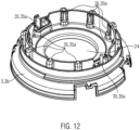
- FIG. 13 12 shows a further exemplary embodiment of part of a foot section 3b for a preparation module 3.
- the foot section 3b has an electrical mating interface 35 which has two power contacts 8a in the form of contact pins and eight auxiliary mating contacts 35b in the form of contact surfaces.
- Such a foot section 3b can, for example, with a kitchen appliance base 2 according to 2 , 3 , 8 and 9 work together.
- the foot section 3b can be arranged on preparation modules 3 with different functions.
- the auxiliary mating contacts 35b are contacted when they are arranged in the receiving area 4, the power mating contacts 35a chronologically after the auxiliary mating contacts 35b.
- FIG. 14 shows the locking counter-element 16 for a preparation module 3 according to FIG Fig.8, Fig.9 and 11 in perspective view.
- the locking section 12 with the locking surfaces 12a is interrupted by the recesses 17.
- the recesses 27 are used to pass through the locking contours 18 of the kitchen appliance base 2 when arranging a preparation module 3 in the receiving area 4.
- the web 26 interacts with the groove 25 - see 12 - Together such that the locking counter-element 16 is rotatably mounted in the form of the locking ring on the foot section 3b of the preparation module 3.
- a cover locking device 30 interacts with the locking counter-element 16 and also positively locks a cover 31 closing the preparation space 3a with the preparation module 3 when the locking counter-element 16 rotates from a release position into a locking position.
- the lid locking device 30 is designed in such a way that, in a first step, the preparation module 3 is locked to the kitchen appliance base 2 so that the lid 31 can be removed when the preparation module is locked, and that the lid 31 can be locked with the preparation module 3 only takes place in a second step.
- the cover locking device 30 has a pivotably mounted functional element 32 which can be moved from a release position shown in the direction of the arrow into a locking position.
- At the Counter locking element 16 is an actuator pin 33 which engages in a corresponding recess 34 on the functional element 32 in order to pivot the functional element 32 .
- the head area 32a of the functional element 32 rotates the cover 31 so that it locks with the preparation module 3 in a form-fitting manner.
- the invention is not limited to the exemplary embodiments shown and described, but also includes all embodiments that have the same effect within the meaning of the invention. It is expressly emphasized that the exemplary embodiments are not limited to all features in combination; rather, each individual partial feature can also have an inventive significance independently of all other partial features. Furthermore, the invention has not yet been limited to the combination of features defined in claim 1, but can also be defined by any other combination of specific features of all the individual features disclosed overall. This means that in principle practically every individual feature of claim 1 can be omitted or replaced by at least one individual feature disclosed elsewhere in the application.
Landscapes
- Engineering & Computer Science (AREA)
- Mechanical Engineering (AREA)
- Food Science & Technology (AREA)
- Food-Manufacturing Devices (AREA)
Priority Applications (4)
| Application Number | Priority Date | Filing Date | Title |
|---|---|---|---|
| EP21192449.3A EP4137019A1 (fr) | 2021-08-20 | 2021-08-20 | Base de robot de cuisine, module de préparation et robot de cuisine |
| AU2022206828A AU2022206828A1 (en) | 2021-08-20 | 2022-07-22 | Kitchen device base, preparation module, and kitchen device |
| US17/888,537 US20230057753A1 (en) | 2021-08-20 | 2022-08-16 | Kitchen appliance base, preparation module and kitchen appliance |
| CN202211005642.1A CN115886607A (zh) | 2021-08-20 | 2022-08-22 | 厨房设备底座、制备模组和厨房设备 |
Applications Claiming Priority (1)
| Application Number | Priority Date | Filing Date | Title |
|---|---|---|---|
| EP21192449.3A EP4137019A1 (fr) | 2021-08-20 | 2021-08-20 | Base de robot de cuisine, module de préparation et robot de cuisine |
Publications (1)
| Publication Number | Publication Date |
|---|---|
| EP4137019A1 true EP4137019A1 (fr) | 2023-02-22 |
Family
ID=77431253
Family Applications (1)
| Application Number | Title | Priority Date | Filing Date |
|---|---|---|---|
| EP21192449.3A Pending EP4137019A1 (fr) | 2021-08-20 | 2021-08-20 | Base de robot de cuisine, module de préparation et robot de cuisine |
Country Status (4)
| Country | Link |
|---|---|
| US (1) | US20230057753A1 (fr) |
| EP (1) | EP4137019A1 (fr) |
| CN (1) | CN115886607A (fr) |
| AU (1) | AU2022206828A1 (fr) |
Citations (4)
| Publication number | Priority date | Publication date | Assignee | Title |
|---|---|---|---|---|
| EP0895742A1 (fr) * | 1997-08-04 | 1999-02-10 | Seb S.A. | Dispositif de connexion pour appareil portatif |
| WO2005070271A2 (fr) * | 2004-01-27 | 2005-08-04 | Mcgill Technology Limited | Melangeur et son procede |
| EP2404536A1 (fr) * | 2010-07-09 | 2012-01-11 | Seb S.A. | Recipient de travail comportant une embase amovible et appareil electromenager de preparation culinaire muni d'un tel recipient |
| EP3287054A1 (fr) * | 2016-08-26 | 2018-02-28 | BSH Hausgeräte GmbH | Dispositif de liaison permettant le raccordement d'un dispositif complémentaire à un appareil ménager |
-
2021
- 2021-08-20 EP EP21192449.3A patent/EP4137019A1/fr active Pending
-
2022
- 2022-07-22 AU AU2022206828A patent/AU2022206828A1/en active Pending
- 2022-08-16 US US17/888,537 patent/US20230057753A1/en active Pending
- 2022-08-22 CN CN202211005642.1A patent/CN115886607A/zh active Pending
Patent Citations (4)
| Publication number | Priority date | Publication date | Assignee | Title |
|---|---|---|---|---|
| EP0895742A1 (fr) * | 1997-08-04 | 1999-02-10 | Seb S.A. | Dispositif de connexion pour appareil portatif |
| WO2005070271A2 (fr) * | 2004-01-27 | 2005-08-04 | Mcgill Technology Limited | Melangeur et son procede |
| EP2404536A1 (fr) * | 2010-07-09 | 2012-01-11 | Seb S.A. | Recipient de travail comportant une embase amovible et appareil electromenager de preparation culinaire muni d'un tel recipient |
| EP3287054A1 (fr) * | 2016-08-26 | 2018-02-28 | BSH Hausgeräte GmbH | Dispositif de liaison permettant le raccordement d'un dispositif complémentaire à un appareil ménager |
Also Published As
| Publication number | Publication date |
|---|---|
| AU2022206828A1 (en) | 2023-03-09 |
| US20230057753A1 (en) | 2023-02-23 |
| CN115886607A (zh) | 2023-04-04 |
Similar Documents
| Publication | Publication Date | Title |
|---|---|---|
| DE68903509T2 (de) | Montagevorrichtung fuer buersten in einem umkehrbaren stromwendermotor. | |
| EP0081874B2 (fr) | Appareil à usage domestique | |
| EP2837989B1 (fr) | Interrupteur rotatif pour appareil électrique doté d'un dispositif d'arrêt amélioré | |
| DE2848824C2 (de) | Anordnung zur Leistungssteuerung | |
| EP0679356B1 (fr) | Mixeur à main électrique avec un dispositif accessoire | |
| DE69001552T2 (de) | Elektrisches Bügeleisen. | |
| EP3530159A1 (fr) | Dispositif de préparation d'aliments à outil amovible | |
| WO2014154545A1 (fr) | Accessoire de préparation avec protection contre les manipulations | |
| EP3536204B1 (fr) | Mélangeur à main commutable entre une durée d'opération courte et longue selon l'outil attaché | |
| DE69503962T2 (de) | Sicherheitsvorrichtung für ein elektrisches bewegliches Bauelement und Grill mit einer derartigen Vorrichtung | |
| EP4137019A1 (fr) | Base de robot de cuisine, module de préparation et robot de cuisine | |
| DE1778820C3 (fr) | ||
| DE3825654C2 (fr) | ||
| DE2930533C2 (de) | Haushaltsgerät, insbesondere Mehrzweck-Küchenmaschine für verschiedene Arbeitsgeräte | |
| EP3892173A1 (fr) | Adaptateur de cuisson pour un robot de cuisine | |
| EP3287056B1 (fr) | Dispositif d'accouplement multifonction pour un broyeur à usages multiples | |
| EP4137018A1 (fr) | Robot de cuisine doté d'un base et d'un module de préparation | |
| DE3720928A1 (de) | Haushaltsgeraet, insbesondere entsafter | |
| EP3287057A1 (fr) | Dispositif de verrouillage destinée à contenir une unité de traitement | |
| EP0004987A1 (fr) | Appareil mélangeur-broyeur électrique de ménage | |
| DE3837961C2 (de) | Küchenmaschine mit aufsetzbarem Elektro-Handquirl als Antrieb | |
| DE69403389T2 (de) | Küchenmaschine | |
| DE102021102660B4 (de) | Zubereitungsgefäß mit einer Verriegelungseinrichtung | |
| EP4233653A1 (fr) | Récipient de préparation pour une base de robot de cuisine et robot de cuisine | |
| EP2559362B1 (fr) | Appareil électroménager motorisé |
Legal Events
| Date | Code | Title | Description |
|---|---|---|---|
| PUAI | Public reference made under article 153(3) epc to a published international application that has entered the european phase |
Free format text: ORIGINAL CODE: 0009012 |
|
| STAA | Information on the status of an ep patent application or granted ep patent |
Free format text: STATUS: THE APPLICATION HAS BEEN PUBLISHED |
|
| AK | Designated contracting states |
Kind code of ref document: A1 Designated state(s): AL AT BE BG CH CY CZ DE DK EE ES FI FR GB GR HR HU IE IS IT LI LT LU LV MC MK MT NL NO PL PT RO RS SE SI SK SM TR |
|
| STAA | Information on the status of an ep patent application or granted ep patent |
Free format text: STATUS: REQUEST FOR EXAMINATION WAS MADE |
|
| 17P | Request for examination filed |
Effective date: 20230822 |
|
| RBV | Designated contracting states (corrected) |
Designated state(s): AL AT BE BG CH CY CZ DE DK EE ES FI FR GB GR HR HU IE IS IT LI LT LU LV MC MK MT NL NO PL PT RO RS SE SI SK SM TR |