EP4136466B1 - Verfahren zur erkennung eines elektrischen isolationsfehlers zwischen einer elektrischen stromquelle und einer elektrischen masse - Google Patents
Verfahren zur erkennung eines elektrischen isolationsfehlers zwischen einer elektrischen stromquelle und einer elektrischen masse Download PDFInfo
- Publication number
- EP4136466B1 EP4136466B1 EP21711569.0A EP21711569A EP4136466B1 EP 4136466 B1 EP4136466 B1 EP 4136466B1 EP 21711569 A EP21711569 A EP 21711569A EP 4136466 B1 EP4136466 B1 EP 4136466B1
- Authority
- EP
- European Patent Office
- Prior art keywords
- electrical
- voltage
- insulation fault
- detection
- power source
- Prior art date
- Legal status (The legal status is an assumption and is not a legal conclusion. Google has not performed a legal analysis and makes no representation as to the accuracy of the status listed.)
- Active
Links
Images


Classifications
-
- G—PHYSICS
- G01—MEASURING; TESTING
- G01R—MEASURING ELECTRIC VARIABLES; MEASURING MAGNETIC VARIABLES
- G01R31/00—Arrangements for testing electric properties; Arrangements for locating electric faults; Arrangements for electrical testing characterised by what is being tested not provided for elsewhere
- G01R31/50—Testing of electric apparatus, lines, cables or components for short-circuits, continuity, leakage current or incorrect line connections
- G01R31/52—Testing for short-circuits, leakage current or ground faults
-
- G—PHYSICS
- G01—MEASURING; TESTING
- G01R—MEASURING ELECTRIC VARIABLES; MEASURING MAGNETIC VARIABLES
- G01R31/00—Arrangements for testing electric properties; Arrangements for locating electric faults; Arrangements for electrical testing characterised by what is being tested not provided for elsewhere
- G01R31/12—Testing dielectric strength or breakdown voltage ; Testing or monitoring effectiveness or level of insulation, e.g. of a cable or of an apparatus, for example using partial discharge measurements; Electrostatic testing
- G01R31/14—Circuits therefor, e.g. for generating test voltages, sensing circuits
-
- G—PHYSICS
- G01—MEASURING; TESTING
- G01R—MEASURING ELECTRIC VARIABLES; MEASURING MAGNETIC VARIABLES
- G01R27/00—Arrangements for measuring resistance, reactance, impedance, or electric characteristics derived therefrom
- G01R27/02—Measuring real or complex resistance, reactance, impedance, or other two-pole characteristics derived therefrom, e.g. time constant
- G01R27/025—Measuring very high resistances, e.g. isolation resistances, i.e. megohm-meters
-
- G—PHYSICS
- G01—MEASURING; TESTING
- G01R—MEASURING ELECTRIC VARIABLES; MEASURING MAGNETIC VARIABLES
- G01R27/00—Arrangements for measuring resistance, reactance, impedance, or electric characteristics derived therefrom
- G01R27/02—Measuring real or complex resistance, reactance, impedance, or other two-pole characteristics derived therefrom, e.g. time constant
- G01R27/20—Measuring earth resistance; Measuring contact resistance, e.g. of earth connections, e.g. plates
- G01R27/205—Measuring contact resistance of connections, e.g. of earth connections
-
- G—PHYSICS
- G01—MEASURING; TESTING
- G01R—MEASURING ELECTRIC VARIABLES; MEASURING MAGNETIC VARIABLES
- G01R31/00—Arrangements for testing electric properties; Arrangements for locating electric faults; Arrangements for electrical testing characterised by what is being tested not provided for elsewhere
- G01R31/005—Testing of electric installations on transport means
- G01R31/006—Testing of electric installations on transport means on road vehicles, e.g. automobiles or trucks
- G01R31/007—Testing of electric installations on transport means on road vehicles, e.g. automobiles or trucks using microprocessors or computers
-
- G—PHYSICS
- G01—MEASURING; TESTING
- G01R—MEASURING ELECTRIC VARIABLES; MEASURING MAGNETIC VARIABLES
- G01R31/00—Arrangements for testing electric properties; Arrangements for locating electric faults; Arrangements for electrical testing characterised by what is being tested not provided for elsewhere
- G01R31/36—Arrangements for testing, measuring or monitoring the electrical condition of accumulators or electric batteries, e.g. capacity or state of charge [SoC]
- G01R31/392—Determining battery ageing or deterioration, e.g. state of health
Definitions
- the present invention relates generally to the electrical safety of electrical energy sources such as storage batteries.
- the invention finds a particularly advantageous application in electrically powered motor vehicles.
- An electrically powered motor vehicle typically consists of an electric motor and a storage battery that is specially designed to supply the electric motor with current to move the vehicle forward.
- Such a storage battery generally comprises a plurality of low-voltage cells, connected in series with each other so that the overall voltage across the battery terminals is high enough to move the vehicle forward.
- the voltage across the terminals of such a battery is often of the order of 400 V.
- Such a battery pack is usually controlled by a management system designed to monitor its proper functioning.
- EP0654673 teaches to measure an insulation resistance between the storage battery and the vehicle body, using a detection circuit which includes a controllable voltage generator and an electrical measuring resistor connected in series between a terminal of the storage battery and the body.
- a disadvantage of this solution is that in practice it wrongly detects measurement errors, so that the time periods during which the measurement results are not usable are long, which can be potentially dangerous if a short circuit occurs.
- Another disadvantage of this solution is that when an electrical insulation fault is detected, it does not allow us to know between which cells of the battery pack this fault is located exactly.
- the document FR3037406A1 describes a solution that also has reliability drawbacks. Furthermore, the document US 2017/106754 A1 also describes an approach for insulation fault detection.
- the The present invention provides a detection method according to claim 1.
- the invention also relates to a device for detecting an electrical insulation fault between an electrical energy source and an electrical mass, according to claim 8.
- the invention also relates to a motor vehicle comprising an electrical energy source, an electrical ground, and a detection device as mentioned above.
- an electrically powered motor vehicle 1 is shown.
- This motor vehicle 1 comprises an electric powertrain 10 which comprises, in this example, an inverter 11 and an electric motor 12.
- the inverter 11 is conventionally designed to convert a direct voltage into an alternating voltage.
- the motor vehicle 1 To supply the inverter 11 with electric current, the motor vehicle 1 has a direct voltage source.
- This source here is a rechargeable 20 accumulator battery.
- Such a storage battery 20 usually comprises a housing which houses a plurality of storage cells 21 of reduced size, including The number is calculated so that the electric motor can develop sufficient torque and power to propel the vehicle for a predetermined duration.
- Each cell usually has a voltage at its terminals of the order of 3 to 5 V. These cells are then connected in series to reach the voltage level required by the application.
- the voltage Vbat measured at the terminals of the traction battery can thus reach more than 400 V when the battery is charged.
- terminals V - and V + The two terminals of the storage battery 20, between which all the storage cells 21 are connected, are called terminals V - and V + .
- the motor vehicle 1 further comprises a frame 30, here formed by the chassis and the body of this vehicle which are generally made of electrically conductive metal material.
- This frame 30 forms a floating electrical mass since it is not permanently electrically connected to the ground.
- This frame 30 is illustrated in the Figures 1 and 2 by an electrical ground symbol.
- the motor vehicle 1 here further comprises, between the terminals of the storage battery 20 and those of the inverter 11, a protection circuit 31 and a power coupling circuit 32.
- the protection circuit 31 includes, in a manner known per se, fuses configured to break the connection in the event of a short circuit.
- a fuse is provided on each electrical line connecting one of the terminals of the storage battery 20 to the inverter 11.
- this protection circuit could comprise only one fuse.
- the power coupling circuit 32 comprises at least one switch for selectively connecting and, alternately, disconnecting the terminals of the storage battery 20 to the inverter 11.
- this circuit is shown as comprising, on each electrical line connecting one of the terminals of the storage battery 20 to the inverter 11, a switch 33, 34.
- this power coupling circuit 32 could comprise only one switch, for example connected between the terminal V + of the storage battery 20 and the inverter 11.
- the motor vehicle 1 also includes a system allowing: measure the insulation of the storage battery 20.
- This system is in practice formed by a detection circuit 40 of an electrical insulation fault between the storage battery 20 and the casing 30.
- This detection circuit 40 which will be described in detail in the remainder of this presentation, is electrically connected to the casing 30 and to a single terminal of the storage battery 20, here the terminal V - .
- the motor vehicle 1 finally comprises a battery management system (BMS) calculator 50.
- BMS battery management system
- This calculator comprises a processor, a memory and a data input and output interface.
- the computer is adapted to receive information from the detection circuit 40 and it is adapted to control the switches 33, 34 of the power coupling circuit 32.
- the calculator stores a computer application, consisting of computer programs comprising instructions whose execution by the processor allows the calculator to implement the method described below.
- this calculator 50 is powered via a direct voltage source 51 separate from the storage battery 20. In this case, this is the power supply battery for the vehicle's on-board network.
- the computer 50 is programmed to control the opening of the two switches 33, 34 of the power coupling circuit 32.
- insulation defect we mean here the abnormal presence of an electrical contact of low electrical resistance between the carcass 30 and an electrical potential point of the storage battery 20.
- This electrical potential point can be formed by one of the terminals V + , V - of the battery, but not only. It can be any area located between these two terminals.
- a resistance is said to be low if it is less than or equal to a predefined safety threshold, for example 100k ⁇ .
- FIG. 2 illustrates a single electrical insulation fault between a point 22 of the accumulator battery source 20 and the frame 30.
- This insulation fault results here in the appearance of an insulation resistance 66 which connects this point 22 and the frame 30 and which has a value, denoted R i , lower than the aforementioned safety threshold.
- the detection circuit 40 is then specifically designed to detect such a situation. To do this, it is based on a modeling of an electrical insulation fault presented in the form of the diagram of the figure 2 .
- the accumulator battery 20 has been represented by means of two direct voltage sources 23, 24 connected in series with each other between the terminals V + , V - , on either side of the point 22.
- the source 41, the parallel RC circuit and the current limiting resistor 42 are connected in series between the V - terminal of the storage battery and the frame 30.
- the source 41 is controlled by the computer 50 to apply a voltage V d which leads to the appearance of an electric current I d which crosses the current limiting resistor 42.
- the value R d of this resistor 52 is then chosen to be sufficiently low to facilitate the measurement of the electric current I d while being sufficiently high not to degrade the electrical insulation of the storage battery 20. It is here at least 5 times higher than the predefined safety threshold (which we recall is here 100k ⁇ ).
- the value R m of the measuring resistor 43 is advantageously chosen so that the ratio R d /R m is between 1 and 100 to maintain the current values I d within a narrow range.
- the detection circuit 40 is here adapted to measure the voltage V m at the terminals of the parallel RC circuit, for example by means of an analog/digital converter based on differential amplifiers, electrically connected in parallel with this parallel RC circuit. Measuring this voltage V m amounts to measuring the current I d .
- the computer 50 implements a loop detection method, with regular time steps. In each loop, the computer proceeds in two phases which can be implemented successively (in any direction) or concomitantly.
- a first phase of the method which consists in detecting a possible insulation defect.
- a second phase which is more precisely the subject of the present invention, and which consists in verifying that the conditions for detecting such a defect were indeed met and that the detection thus carried out was reliable.
- the calculator 50 controls the source 41 such that it applies during a first period T1 a first voltage of value noted V d1 , since it applies during a second period T2 a second voltage of value noted V d2 .
- each period has a duration of the order of a second.
- V d1 , V d2 of the applied voltage are different here, but they are of the same polarity.
- Each of these values corresponds to a value I d1 , I d2 of current I d , and a value V m1 , V m2 of voltage V m .
- the current I d and the measured voltage V m first exhibit a phase called transient state, during which their values vary significantly, followed by a phase called steady state, during which their values stabilize around a constant. It is preferable to wait until steady state is established to measure the values V m1 , V m2 of voltage V m . In practice, the measurement of these values occurs at the end of periods T 1 , T 2 .
- the values taken by the measured voltage V m are generally noisy.
- the results of the two equations used are then filtered.
- an RLS filter (from the English "Recursive least squares") will be used in order to obtain a stable approximation of the value R i of the insulation resistance 66 and the coefficient ⁇ .
- the calculator compares this value R i with the safety threshold predefined (which here is 100k ⁇ ).
- the calculator implements the second phase of the process to check that this detection is reliable.
- the second phase will therefore make it possible to check whether or not we are in one of these risky situations.
- the first example of a risk situation is linked to the switching of the switch(es) 33, 34 of the power coupling circuit 32.
- closing the switch(es) 33, 34 allows the storage battery 20 to be connected to the inverter 11. It is, for example, controlled each time the vehicle is started after prolonged parking. It therefore occurs regularly.
- transition between the states E T “open” and “closed” is not instantaneous, but is necessarily accompanied by an intermediate state called “transient”, reflecting the phenomena of charging and discharging of the control coils of the switches 33, 34.
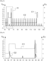
- Curve C2 represents the variations in the value V m of the measured voltage when source 41 periodically establishes the same voltage at its terminals.
- the second example of a risky situation is related to the charger of the traction battery 20.
- the motor vehicle 1 is of the rechargeable electric type, it is equipped with an electric charger for recharging the storage battery 20 on an electrical outlet of a local electrical network (for example a socket in a home). The terminals of this charger are then respectively connected to the terminals of the storage battery 20.
- a local electrical network for example a socket in a home
- the detection of an electrical insulation fault is no longer handled by the battery manager calculator 50, but by a third-party calculator fitted to the charger.
- the connected or disconnected state Es of the charger is represented using curve C3.
- This curve takes the value 1 when the charger is connected to the local electrical network, and the value 0 when it is disconnected.
- Curve C4 represents the variations in the measured voltage V m .
- the source 41 when the charger is in the disconnected state, the source 41 periodically establishes a voltage at its terminals to detect an electrical insulation fault. No such voltage is, however, established by the source 41 when the charger is connected.
- the present invention proposes to identify risky situations (in which an electrical insulation fault risks being wrongly detected), using simple but effective criteria. It thus proposes to identify these risky situations based solely on the shape of the variations in the signal of the measured voltage V m .
- the present invention proposes to rely on at least two parameters.
- control of the validity of an insulation fault detection is based on the exploitation of exactly two parameters.
- the calculator 50 acquires the two previously measured voltage values Vm 1 , Vm 2 . It also acquires the values (denoted ⁇ V m,t-1 , V 0 , t-1 ) of the two parameters ⁇ V m , V 0 calculated at the previous time step.
- the calculator calculates the instantaneous values (noted ⁇ V m,t , Va,t) of the two parameters ⁇ V m , Va.
- the calculator 50 observes the variations over time of the two parameters in order to detect whether it is in a situation at risk of false detection of an electrical insulation fault.
- the calculator 50 then deduces from the result of these two inequalities the level reliability of the insulation resistance value R i obtained during the first phase of the process.
- This reliability level is of the Boolean type and can take two states: “reliable” and “not reliable”.
- the calculator 50 can be programmed in different ways to exploit the two aforementioned inequalities.
- the calculator 50 considers that the result of the first phase is not reliable. Consequently, no operation is undertaken on the basis of the insulation resistance value R i 66.
- the computer stores the value R i of the insulation resistance 66 and the coefficient ⁇ , and this data is then used to control, for example, the opening of the switch(es) 33, 34.
- the calculator 50 is programmed to check whether these two inequalities are simultaneously false. If this is the case, it considers that the result of the first phase is not reliable. Otherwise, the result of the first phase is considered reliable.
- the second phase could be implemented before the first phase, and the implementation of the first phase could be conditional on the outcome of the second phase.
- the calculator 50 calculates the value R i of the insulation resistance 66 and the coefficient ⁇ and then directly uses this data.
- the two parameters used could be different from those used in the described embodiment.
- the two parameters ⁇ V m , V 0 are characteristics of the signal of the measured voltage V m .
- these two parameters could be simple functions of the values of the measured voltage V m .
- these two parameters could be formed by the value R i of the insulation resistance 66 and by that of the coefficient ⁇ .
- the two aforementioned inequalities could be based on the variations of the two parameters not between two successive time steps, but between a greater number of time steps.
- the two aforementioned inequalities could be based not on the variations of the two parameters over time, but on the values of these two parameters.
Landscapes
- Physics & Mathematics (AREA)
- General Physics & Mathematics (AREA)
- Engineering & Computer Science (AREA)
- Computer Hardware Design (AREA)
- Microelectronics & Electronic Packaging (AREA)
- Chemical & Material Sciences (AREA)
- Combustion & Propulsion (AREA)
- Testing Of Short-Circuits, Discontinuities, Leakage, Or Incorrect Line Connections (AREA)
- Measurement Of Resistance Or Impedance (AREA)
Claims (9)
- Verfahren zur Erkennung eines elektrischen Isolationsfehlers zwischen einer elektrischen Energiequelle (20) und einer elektrischen Masse (30) mittels einer Schaltung (40), die einen ansteuerbaren Spannungsgenerator (41) und einen elektrischen Messwiderstand (43) umfasst, die in Reihe zwischen einer Klemme der elektrischen Energiequelle (20) und der elektrischen Masse (30) angeschlossen sind, und die auch ein Messmittel (45) zum Messen der Spannung (Vm) an den Klemmen des elektrischen Messwiderstands aufweist, wobei das Verfahren die folgenden Schritte umfasst:- Ansteuern des Spannungsgenerators (41), so dass er zwischen seinen Klemmen eine Spannung (Vd) mit einem Wert ungleich null aufbaut, und- Messen der Spannung (Vm) an den Klemmen des elektrischen Messwiderstands (43), um einen elektrischen Isolationsfehler zwischen der elektrischen Energiequelle (20) und der elektrischen Masse (30) zu erkennen, dadurch gekennzeichnet, dass:bei dem Schritt des Ansteuerns der Spannungsgenerator (41) so angesteuert wird, dass die Spannung (Vd) während zwei aufeinanderfolgender Perioden (T1, T2) zwei Werte (Vd1, Vd2) annimmt, die ungleich null und voneinander verschieden sind,bei dem Schritt des Messens zwei Werte (Vm1, Vm2) der Spannung (Vm) an den Klemmen des elektrischen Messwiderstands (43) jeweils während der beiden Perioden (T1, T2) gemessen werden, unddadurch, dass das Verfahren ferner einen Schritt des Kontrollierens umfasst, in dessen Verlauf ein Rechner:- in Abhängigkeit mindestens von den Werten (Vm1, Vm2) der Spannung (Vm) , die an den Klemmen des elektrischen Messwiderstands (43) gemessen werden, mindestens zwei Parameter (ΔVm, V0) bestimmt, die charakteristisch für eine Störung sind, die die Erkennung des elektrischen Isolationsfehlers beeinflusst, wobei der eine der Parameter (V0) eine Funktion des arithmetischen Mittelwerts zwischen den beiden gemessen Werten (Vm1, Vm2) der Spannung (Vm) an den Klemmen des elektrischen Messwiderstands (43) und/oder eine Funktion der Differenz (ΔVm) zwischen den beiden gemessenen Werten (Vm1, Vm2) der Spannung (Vm) an den Klemmen des elektrischen Messwiderstands (43) ist,- ein Zuverlässigkeitsniveau der Erkennung des elektrischen Isolationsfehlers in Abhängigkeit von mindestens dem einen der beiden Parameter (ΔVm, V0) berechnet.
- Verfahren zur Erkennung nach Anspruch 1, bei dem zwischen dem Schritt des Messens und dem Schritt des Kontrollierens ein Schritt des Erkennens des elektrischen Isolationsfehlers vorgesehen ist und bei dem das Ergebnis des Schritts des Erkennens in Abhängigkeit von dem berechneten Zuverlässigkeitsniveau ausgewertet wird oder nicht.
- Verfahren zur Erkennung nach Anspruch 1, bei dem nach dem Schritt des Kontrollierens ein Schritt des Erkennens des elektrischen Isolationsfehles nur vorgesehen ist, wenn das Zuverlässigkeitsniveau angibt, dass die Erkennung des elektrischen Isolationsfehlers zuverlässig ist.
- Verfahren zur Erkennung nach einem der vorhergehenden Ansprüche, bei dem der Rechner, zum Erkennen eines elektrischen Isolationsfehlers, den Wert (Ri) eines Isolationswiderstands (66) der elektrischen Energiequelle (20) bezogen auf die elektrische Masse (30) berechnet, dann den Wert (Ri) mit einem Schwellenwert vergleicht.
- Verfahren zur Erkennung nach einem der vorhergehenden Ansprüche, bei dem der Rechner, wenn ein elektrischer Isolationsfehler erkannt wird, einen Positionierungskoeffizienten (α) des elektrischen Isolationsfehlers in der elektrischen Energiequelle (20) berechnet.
- Verfahren zur Erkennung nach einem der vorhergehenden Ansprüche, bei dem, bei dem Schritt des Kontrollieren, das Berechnen des Zuverlässigkeitsniveaus in Abhängigkeit von den beiden Parametern (ΔVm, V0) ausgeführt wird.
- Verfahren zur Erkennung nach einem der vorhergehenden Ansprüche, bei dem, bei dem Schritt des Kontrollierens, das Berechnen des Zuverlässigkeitsniveaus in Abhängigkeit von der zeitlichen Änderung mindestens des einen der beiden Parameter (ΔVm, V0) ausgeführt wird.
- Vorrichtung zur Erkennung eines elektrischen Isolationsfehlers zwischen einer elektrischen Energiequelle (20) und einer elektrischen Masse (30), umfassend:- eine Schaltung (40), die einen ansteuerbaren Spannungsgenerator (41) und einen elektrischen Messwiderstand (43) umfasst, die in Reihe zwischen einer Klemme der elektrischen Energiequelle (20) und der elektrischen Masse (30) angeschlossen sind, und die ein Messmittel (45) zum Messen der Stärke des Stroms (id) aufweist, der durch den elektrischen Messwiderstand (43) fließt, und- einen Rechner, der geeignet ist, ein Verfahren zur Erkennung nach einem der vorhergehenden Ansprüche durchzuführen.
- Kraftfahrzeug, umfassend eine elektrische Energiequelle (20) und eine elektrische Masse (30), dadurch gekennzeichnet, dass es eine Vorrichtung zur Erkennung nach dem vorhergehenden Anspruch umfasst.
Applications Claiming Priority (2)
| Application Number | Priority Date | Filing Date | Title |
|---|---|---|---|
| FR2003722A FR3109222B1 (fr) | 2020-04-14 | 2020-04-14 | Procédé de détection d’un défaut d’isolation électrique entre une source d’énergie électrique et une masse électrique |
| PCT/EP2021/056592 WO2021209207A1 (fr) | 2020-04-14 | 2021-03-16 | Procede de detection d'un defaut d'isolation electrique entre une source d'energie electrique et une masse electrique |
Publications (2)
| Publication Number | Publication Date |
|---|---|
| EP4136466A1 EP4136466A1 (de) | 2023-02-22 |
| EP4136466B1 true EP4136466B1 (de) | 2024-10-30 |
Family
ID=70918672
Family Applications (1)
| Application Number | Title | Priority Date | Filing Date |
|---|---|---|---|
| EP21711569.0A Active EP4136466B1 (de) | 2020-04-14 | 2021-03-16 | Verfahren zur erkennung eines elektrischen isolationsfehlers zwischen einer elektrischen stromquelle und einer elektrischen masse |
Country Status (7)
| Country | Link |
|---|---|
| US (1) | US12210052B2 (de) |
| EP (1) | EP4136466B1 (de) |
| JP (1) | JP7723885B2 (de) |
| KR (1) | KR20230002747A (de) |
| CN (1) | CN115443412A (de) |
| FR (1) | FR3109222B1 (de) |
| WO (1) | WO2021209207A1 (de) |
Families Citing this family (4)
| Publication number | Priority date | Publication date | Assignee | Title |
|---|---|---|---|---|
| CN112363070B (zh) * | 2021-01-14 | 2021-06-22 | 江苏固德威电源科技股份有限公司 | 电池拉弧检测方法、装置和电池储能系统 |
| DE102021127848A1 (de) * | 2021-10-26 | 2023-04-27 | Bender Gmbh & Co. Kg | Verfahren und Vorrichtung zur Erkennung und Lokalisierung von zyklischen Kurzzeit-Isolationsfehlern in einem ungeerdeten Stromversorgungssystem |
| FR3134189B1 (fr) | 2022-03-29 | 2025-04-04 | Psa Automobiles Sa | Procede de controle d’un vehicule comprenant un dispositif de test d’isolement d’un circuit electrique |
| CN118795282B (zh) * | 2024-09-10 | 2024-11-15 | 山东理工大学 | 一种电力电缆终端接头温度监测及降温方法 |
Family Cites Families (8)
| Publication number | Priority date | Publication date | Assignee | Title |
|---|---|---|---|---|
| DE4339946A1 (de) | 1993-11-24 | 1995-06-01 | Walther Bender Gmbh & Co Kg Di | Verfahren und Einrichtung zur Isolationsüberwachung vom ungeerdeten Gleich- und Wechselstromnetzen |
| JPH0969879A (ja) * | 1995-08-30 | 1997-03-11 | Hitachi Ltd | 加入者回線上における絶縁抵抗/容量試験方法、並びに加入者回路 |
| KR100999852B1 (ko) * | 2008-04-14 | 2010-12-09 | 주식회사 케피코 | 전기 자동차의 누전 검출 장치 및 이를 이용한 누전 검출방법 |
| JP2012037468A (ja) * | 2010-08-11 | 2012-02-23 | Tohoku Denki Hoan Kyokai | 絶縁抵抗計 |
| FR3014206B1 (fr) * | 2013-12-04 | 2015-12-11 | Renault Sas | Estimation de la resistance d'isolement entre une batterie de vehicule automobile et la masse |
| DE102014205877B4 (de) * | 2014-03-28 | 2019-08-22 | Continental Automotive Gmbh | Vorrichtung und Verfahren zur Überwachung einer elektrischen Isolation bei einem Bordnetz |
| FR3037406B1 (fr) * | 2015-06-15 | 2017-06-02 | Renault Sas | Systeme electrique comportant un circuit de detection d’un defaut d’isolement electrique |
| CN108922779A (zh) * | 2018-07-12 | 2018-11-30 | 中国振华集团云科电子有限公司 | 一种片式通孔金电极芯片电容器及其制备方法 |
-
2020
- 2020-04-14 FR FR2003722A patent/FR3109222B1/fr active Active
-
2021
- 2021-03-16 KR KR1020227039852A patent/KR20230002747A/ko active Pending
- 2021-03-16 JP JP2022562665A patent/JP7723885B2/ja active Active
- 2021-03-16 US US17/996,319 patent/US12210052B2/en active Active
- 2021-03-16 WO PCT/EP2021/056592 patent/WO2021209207A1/fr not_active Ceased
- 2021-03-16 CN CN202180030936.7A patent/CN115443412A/zh active Pending
- 2021-03-16 EP EP21711569.0A patent/EP4136466B1/de active Active
Also Published As
| Publication number | Publication date |
|---|---|
| KR20230002747A (ko) | 2023-01-05 |
| CN115443412A (zh) | 2022-12-06 |
| FR3109222B1 (fr) | 2023-06-16 |
| JP2023522322A (ja) | 2023-05-30 |
| JP7723885B2 (ja) | 2025-08-15 |
| US20230228802A1 (en) | 2023-07-20 |
| WO2021209207A1 (fr) | 2021-10-21 |
| US12210052B2 (en) | 2025-01-28 |
| EP4136466A1 (de) | 2023-02-22 |
| FR3109222A1 (fr) | 2021-10-15 |
Similar Documents
| Publication | Publication Date | Title |
|---|---|---|
| EP4136466B1 (de) | Verfahren zur erkennung eines elektrischen isolationsfehlers zwischen einer elektrischen stromquelle und einer elektrischen masse | |
| EP3308177B1 (de) | Elektrisches system mit einer schaltung zum erfassen eines elektrischen isolationsfehlers | |
| EP1685622B1 (de) | Gleichgewichts-ladeverfahren für eine lithiumionen- oder lithiumpolymerbatterie | |
| EP2797157B1 (de) | Leistungsstarkes Batteriesystem zur Bestimmung der Impedanz eines Moduls | |
| EP2721684B1 (de) | Batteriezellensystem mit vereinfachter überwachung | |
| EP2890990B1 (de) | Vorrichtung zum nachweis und zur messung eines isolationsfehlers | |
| EP3655788B1 (de) | Verfahren zur erkennung eines selbstentladungsdefekts in einer batteriezelle | |
| WO2008065273A2 (fr) | Procede de gestion de charge d'une batterie rechargeable | |
| WO2012171818A1 (fr) | Dispositif de detection d'un defaut d'isolement | |
| EP2994341A1 (de) | Sicherheitssystem für ein akkumulatorbatteriemodul und entsprechendes verfahren zum auswuchten eines batteriemoduls | |
| EP3047290B1 (de) | Verfahren zur schätzung der alterung einer zelle eines akkumulators | |
| EP3704504A1 (de) | Verfahren zur bestimmung des zustandes einer elektrischen leitung, die eine batteriezelle mit einer überwachungseinheit verbindet, und entsprechende überwachungseinheit | |
| EP2859636B1 (de) | Gegen externe kurzschlüsse geschützte akkumulatorenbatterie | |
| EP3590172B1 (de) | Verfahren zur steuerung einer bordeigenen, an ein einphasiges oder dreiphasiges stromversorgungsnetz angeschlossenen fahrzeugbatterieladevorrichtung | |
| EP4038398A1 (de) | Verfahren zur schätzung des isolationswiderstandes einer hochspannungsschaltung in einem elektrischen oder hybriden kraftfahrzeug | |
| EP2668064B1 (de) | Steuerung verfahren einer kraftfahrzeugs akkumulator | |
| EP4445158A1 (de) | Verfahren zur bestimmung und rücksetzung des ladezustands der batterien eines hybridfahrzeugs | |
| WO2022229523A1 (fr) | Supervision d'une batterie électrique pour véhicule automobile | |
| EP2426807B1 (de) | Schutz einer Dünnschichtbatterie | |
| WO2021058278A1 (fr) | Systeme de protection d'un dispositif a resistance interne variable | |
| FR2849298A1 (fr) | Dispositif de controle de l'etat de charge, a tension constante, d'un ensemble de batterie a generateurs electrochimiques secondaires | |
| FR3159016A1 (fr) | Procédé de détection d’un défaut d’arc électrique pour un système de batterie | |
| FR3160017A1 (fr) | Procede de diagnostic d’un systeme electrique de puissance pour un vehicule electrifie | |
| EP4466548A1 (de) | Verfahren zur überwachung eines isolationsfehlers in einer aufladeschaltung | |
| FR3127816A1 (fr) | Procede de surveillance d’une batterie pour vehicule automobile |
Legal Events
| Date | Code | Title | Description |
|---|---|---|---|
| STAA | Information on the status of an ep patent application or granted ep patent |
Free format text: STATUS: UNKNOWN |
|
| STAA | Information on the status of an ep patent application or granted ep patent |
Free format text: STATUS: THE INTERNATIONAL PUBLICATION HAS BEEN MADE |
|
| PUAI | Public reference made under article 153(3) epc to a published international application that has entered the european phase |
Free format text: ORIGINAL CODE: 0009012 |
|
| STAA | Information on the status of an ep patent application or granted ep patent |
Free format text: STATUS: REQUEST FOR EXAMINATION WAS MADE |
|
| 17P | Request for examination filed |
Effective date: 20220930 |
|
| AK | Designated contracting states |
Kind code of ref document: A1 Designated state(s): AL AT BE BG CH CY CZ DE DK EE ES FI FR GB GR HR HU IE IS IT LI LT LU LV MC MK MT NL NO PL PT RO RS SE SI SK SM TR |
|
| DAV | Request for validation of the european patent (deleted) | ||
| DAX | Request for extension of the european patent (deleted) | ||
| P01 | Opt-out of the competence of the unified patent court (upc) registered |
Effective date: 20230608 |
|
| RAP1 | Party data changed (applicant data changed or rights of an application transferred) |
Owner name: AMPERE SAS |
|
| GRAP | Despatch of communication of intention to grant a patent |
Free format text: ORIGINAL CODE: EPIDOSNIGR1 |
|
| STAA | Information on the status of an ep patent application or granted ep patent |
Free format text: STATUS: GRANT OF PATENT IS INTENDED |
|
| INTG | Intention to grant announced |
Effective date: 20240521 |
|
| GRAS | Grant fee paid |
Free format text: ORIGINAL CODE: EPIDOSNIGR3 |
|
| GRAA | (expected) grant |
Free format text: ORIGINAL CODE: 0009210 |
|
| STAA | Information on the status of an ep patent application or granted ep patent |
Free format text: STATUS: THE PATENT HAS BEEN GRANTED |
|
| AK | Designated contracting states |
Kind code of ref document: B1 Designated state(s): AL AT BE BG CH CY CZ DE DK EE ES FI FR GB GR HR HU IE IS IT LI LT LU LV MC MK MT NL NO PL PT RO RS SE SI SK SM TR |
|
| REG | Reference to a national code |
Ref country code: GB Ref legal event code: FG4D Free format text: NOT ENGLISH |
|
| REG | Reference to a national code |
Ref country code: CH Ref legal event code: EP |
|
| REG | Reference to a national code |
Ref country code: IE Ref legal event code: FG4D Free format text: LANGUAGE OF EP DOCUMENT: FRENCH |
|
| REG | Reference to a national code |
Ref country code: DE Ref legal event code: R096 Ref document number: 602021020991 Country of ref document: DE |
|
| REG | Reference to a national code |
Ref country code: LT Ref legal event code: MG9D |
|
| REG | Reference to a national code |
Ref country code: NL Ref legal event code: MP Effective date: 20241030 |
|
| PG25 | Lapsed in a contracting state [announced via postgrant information from national office to epo] |
Ref country code: IS Free format text: LAPSE BECAUSE OF FAILURE TO SUBMIT A TRANSLATION OF THE DESCRIPTION OR TO PAY THE FEE WITHIN THE PRESCRIBED TIME-LIMIT Effective date: 20250228 Ref country code: PT Free format text: LAPSE BECAUSE OF FAILURE TO SUBMIT A TRANSLATION OF THE DESCRIPTION OR TO PAY THE FEE WITHIN THE PRESCRIBED TIME-LIMIT Effective date: 20250228 Ref country code: HR Free format text: LAPSE BECAUSE OF FAILURE TO SUBMIT A TRANSLATION OF THE DESCRIPTION OR TO PAY THE FEE WITHIN THE PRESCRIBED TIME-LIMIT Effective date: 20241030 |
|
| PGFP | Annual fee paid to national office [announced via postgrant information from national office to epo] |
Ref country code: DE Payment date: 20250319 Year of fee payment: 5 |
|
| PG25 | Lapsed in a contracting state [announced via postgrant information from national office to epo] |
Ref country code: FI Free format text: LAPSE BECAUSE OF FAILURE TO SUBMIT A TRANSLATION OF THE DESCRIPTION OR TO PAY THE FEE WITHIN THE PRESCRIBED TIME-LIMIT Effective date: 20241030 Ref country code: NL Free format text: LAPSE BECAUSE OF FAILURE TO SUBMIT A TRANSLATION OF THE DESCRIPTION OR TO PAY THE FEE WITHIN THE PRESCRIBED TIME-LIMIT Effective date: 20241030 |
|
| REG | Reference to a national code |
Ref country code: AT Ref legal event code: MK05 Ref document number: 1737371 Country of ref document: AT Kind code of ref document: T Effective date: 20241030 |
|
| PG25 | Lapsed in a contracting state [announced via postgrant information from national office to epo] |
Ref country code: BG Free format text: LAPSE BECAUSE OF FAILURE TO SUBMIT A TRANSLATION OF THE DESCRIPTION OR TO PAY THE FEE WITHIN THE PRESCRIBED TIME-LIMIT Effective date: 20241030 |
|
| PG25 | Lapsed in a contracting state [announced via postgrant information from national office to epo] |
Ref country code: ES Free format text: LAPSE BECAUSE OF FAILURE TO SUBMIT A TRANSLATION OF THE DESCRIPTION OR TO PAY THE FEE WITHIN THE PRESCRIBED TIME-LIMIT Effective date: 20241030 |
|
| PG25 | Lapsed in a contracting state [announced via postgrant information from national office to epo] |
Ref country code: NO Free format text: LAPSE BECAUSE OF FAILURE TO SUBMIT A TRANSLATION OF THE DESCRIPTION OR TO PAY THE FEE WITHIN THE PRESCRIBED TIME-LIMIT Effective date: 20250130 |
|
| PG25 | Lapsed in a contracting state [announced via postgrant information from national office to epo] |
Ref country code: AT Free format text: LAPSE BECAUSE OF FAILURE TO SUBMIT A TRANSLATION OF THE DESCRIPTION OR TO PAY THE FEE WITHIN THE PRESCRIBED TIME-LIMIT Effective date: 20241030 Ref country code: GR Free format text: LAPSE BECAUSE OF FAILURE TO SUBMIT A TRANSLATION OF THE DESCRIPTION OR TO PAY THE FEE WITHIN THE PRESCRIBED TIME-LIMIT Effective date: 20250131 Ref country code: LV Free format text: LAPSE BECAUSE OF FAILURE TO SUBMIT A TRANSLATION OF THE DESCRIPTION OR TO PAY THE FEE WITHIN THE PRESCRIBED TIME-LIMIT Effective date: 20241030 |
|
| PG25 | Lapsed in a contracting state [announced via postgrant information from national office to epo] |
Ref country code: PL Free format text: LAPSE BECAUSE OF FAILURE TO SUBMIT A TRANSLATION OF THE DESCRIPTION OR TO PAY THE FEE WITHIN THE PRESCRIBED TIME-LIMIT Effective date: 20241030 |
|
| PGFP | Annual fee paid to national office [announced via postgrant information from national office to epo] |
Ref country code: FR Payment date: 20250326 Year of fee payment: 5 |
|
| PGFP | Annual fee paid to national office [announced via postgrant information from national office to epo] |
Ref country code: GB Payment date: 20250326 Year of fee payment: 5 |
|
| PG25 | Lapsed in a contracting state [announced via postgrant information from national office to epo] |
Ref country code: RS Free format text: LAPSE BECAUSE OF FAILURE TO SUBMIT A TRANSLATION OF THE DESCRIPTION OR TO PAY THE FEE WITHIN THE PRESCRIBED TIME-LIMIT Effective date: 20250130 |
|
| PG25 | Lapsed in a contracting state [announced via postgrant information from national office to epo] |
Ref country code: SM Free format text: LAPSE BECAUSE OF FAILURE TO SUBMIT A TRANSLATION OF THE DESCRIPTION OR TO PAY THE FEE WITHIN THE PRESCRIBED TIME-LIMIT Effective date: 20241030 |
|
| PG25 | Lapsed in a contracting state [announced via postgrant information from national office to epo] |
Ref country code: DK Free format text: LAPSE BECAUSE OF FAILURE TO SUBMIT A TRANSLATION OF THE DESCRIPTION OR TO PAY THE FEE WITHIN THE PRESCRIBED TIME-LIMIT Effective date: 20241030 |
|
| PG25 | Lapsed in a contracting state [announced via postgrant information from national office to epo] |
Ref country code: EE Free format text: LAPSE BECAUSE OF FAILURE TO SUBMIT A TRANSLATION OF THE DESCRIPTION OR TO PAY THE FEE WITHIN THE PRESCRIBED TIME-LIMIT Effective date: 20241030 |
|
| PG25 | Lapsed in a contracting state [announced via postgrant information from national office to epo] |
Ref country code: RO Free format text: LAPSE BECAUSE OF FAILURE TO SUBMIT A TRANSLATION OF THE DESCRIPTION OR TO PAY THE FEE WITHIN THE PRESCRIBED TIME-LIMIT Effective date: 20241030 |
|
| PG25 | Lapsed in a contracting state [announced via postgrant information from national office to epo] |
Ref country code: SK Free format text: LAPSE BECAUSE OF FAILURE TO SUBMIT A TRANSLATION OF THE DESCRIPTION OR TO PAY THE FEE WITHIN THE PRESCRIBED TIME-LIMIT Effective date: 20241030 |
|
| PG25 | Lapsed in a contracting state [announced via postgrant information from national office to epo] |
Ref country code: CZ Free format text: LAPSE BECAUSE OF FAILURE TO SUBMIT A TRANSLATION OF THE DESCRIPTION OR TO PAY THE FEE WITHIN THE PRESCRIBED TIME-LIMIT Effective date: 20241030 |
|
| PG25 | Lapsed in a contracting state [announced via postgrant information from national office to epo] |
Ref country code: IT Free format text: LAPSE BECAUSE OF FAILURE TO SUBMIT A TRANSLATION OF THE DESCRIPTION OR TO PAY THE FEE WITHIN THE PRESCRIBED TIME-LIMIT Effective date: 20241030 |
|
| REG | Reference to a national code |
Ref country code: DE Ref legal event code: R097 Ref document number: 602021020991 Country of ref document: DE |
|
| PLBE | No opposition filed within time limit |
Free format text: ORIGINAL CODE: 0009261 |
|
| STAA | Information on the status of an ep patent application or granted ep patent |
Free format text: STATUS: NO OPPOSITION FILED WITHIN TIME LIMIT |
|
| PG25 | Lapsed in a contracting state [announced via postgrant information from national office to epo] |
Ref country code: SE Free format text: LAPSE BECAUSE OF FAILURE TO SUBMIT A TRANSLATION OF THE DESCRIPTION OR TO PAY THE FEE WITHIN THE PRESCRIBED TIME-LIMIT Effective date: 20241030 |
|
| 26N | No opposition filed |
Effective date: 20250731 |
|
| PG25 | Lapsed in a contracting state [announced via postgrant information from national office to epo] |
Ref country code: MC Free format text: LAPSE BECAUSE OF FAILURE TO SUBMIT A TRANSLATION OF THE DESCRIPTION OR TO PAY THE FEE WITHIN THE PRESCRIBED TIME-LIMIT Effective date: 20241030 |
|
| REG | Reference to a national code |
Ref country code: CH Ref legal event code: H13 Free format text: ST27 STATUS EVENT CODE: U-0-0-H10-H13 (AS PROVIDED BY THE NATIONAL OFFICE) Effective date: 20251023 |
|
| PG25 | Lapsed in a contracting state [announced via postgrant information from national office to epo] |
Ref country code: LU Free format text: LAPSE BECAUSE OF NON-PAYMENT OF DUE FEES Effective date: 20250316 |
|
| REG | Reference to a national code |
Ref country code: BE Ref legal event code: MM Effective date: 20250331 |
|
| PG25 | Lapsed in a contracting state [announced via postgrant information from national office to epo] |
Ref country code: BE Free format text: LAPSE BECAUSE OF NON-PAYMENT OF DUE FEES Effective date: 20250331 |
|
| PG25 | Lapsed in a contracting state [announced via postgrant information from national office to epo] |
Ref country code: CH Free format text: LAPSE BECAUSE OF NON-PAYMENT OF DUE FEES Effective date: 20250331 |
|
| PG25 | Lapsed in a contracting state [announced via postgrant information from national office to epo] |
Ref country code: IE Free format text: LAPSE BECAUSE OF NON-PAYMENT OF DUE FEES Effective date: 20250316 |