EP4136357B1 - Dispositif de maintien et de libération à bas choc et réutilisable - Google Patents
Dispositif de maintien et de libération à bas choc et réutilisable Download PDFInfo
- Publication number
- EP4136357B1 EP4136357B1 EP21725574.4A EP21725574A EP4136357B1 EP 4136357 B1 EP4136357 B1 EP 4136357B1 EP 21725574 A EP21725574 A EP 21725574A EP 4136357 B1 EP4136357 B1 EP 4136357B1
- Authority
- EP
- European Patent Office
- Prior art keywords
- segments
- component
- release
- transmission bar
- holding
- Prior art date
- Legal status (The legal status is an assumption and is not a legal conclusion. Google has not performed a legal analysis and makes no representation as to the accuracy of the status listed.)
- Active
Links
Images


Classifications
-
- F—MECHANICAL ENGINEERING; LIGHTING; HEATING; WEAPONS; BLASTING
- F16—ENGINEERING ELEMENTS AND UNITS; GENERAL MEASURES FOR PRODUCING AND MAINTAINING EFFECTIVE FUNCTIONING OF MACHINES OR INSTALLATIONS; THERMAL INSULATION IN GENERAL
- F16B—DEVICES FOR FASTENING OR SECURING CONSTRUCTIONAL ELEMENTS OR MACHINE PARTS TOGETHER, e.g. NAILS, BOLTS, CIRCLIPS, CLAMPS, CLIPS OR WEDGES; JOINTS OR JOINTING
- F16B2/00—Friction-grip releasable fastenings
- F16B2/02—Clamps, i.e. with gripping action effected by positive means other than the inherent resistance to deformation of the material of the fastening
- F16B2/06—Clamps, i.e. with gripping action effected by positive means other than the inherent resistance to deformation of the material of the fastening external, i.e. with contracting action
- F16B2/12—Clamps, i.e. with gripping action effected by positive means other than the inherent resistance to deformation of the material of the fastening external, i.e. with contracting action using sliding jaws
-
- B—PERFORMING OPERATIONS; TRANSPORTING
- B64—AIRCRAFT; AVIATION; COSMONAUTICS
- B64G—COSMONAUTICS; VEHICLES OR EQUIPMENT THEREFOR
- B64G1/00—Cosmonautic vehicles
- B64G1/22—Parts of, or equipment specially adapted for fitting in or to, cosmonautic vehicles
- B64G1/222—Parts of, or equipment specially adapted for fitting in or to, cosmonautic vehicles for deploying structures between a stowed and deployed state
- B64G1/2221—Parts of, or equipment specially adapted for fitting in or to, cosmonautic vehicles for deploying structures between a stowed and deployed state characterised by the manner of deployment
- B64G1/2222—Folding
-
- B—PERFORMING OPERATIONS; TRANSPORTING
- B64—AIRCRAFT; AVIATION; COSMONAUTICS
- B64G—COSMONAUTICS; VEHICLES OR EQUIPMENT THEREFOR
- B64G1/00—Cosmonautic vehicles
- B64G1/22—Parts of, or equipment specially adapted for fitting in or to, cosmonautic vehicles
- B64G1/222—Parts of, or equipment specially adapted for fitting in or to, cosmonautic vehicles for deploying structures between a stowed and deployed state
- B64G1/2228—Parts of, or equipment specially adapted for fitting in or to, cosmonautic vehicles for deploying structures between a stowed and deployed state characterised by the hold-down or release mechanisms
-
- B—PERFORMING OPERATIONS; TRANSPORTING
- B64—AIRCRAFT; AVIATION; COSMONAUTICS
- B64G—COSMONAUTICS; VEHICLES OR EQUIPMENT THEREFOR
- B64G1/00—Cosmonautic vehicles
- B64G1/22—Parts of, or equipment specially adapted for fitting in or to, cosmonautic vehicles
- B64G1/64—Systems for coupling or separating cosmonautic vehicles or parts thereof, e.g. docking arrangements
- B64G1/645—Separators
- B64G1/6457—Springs; Shape memory actuators
-
- F—MECHANICAL ENGINEERING; LIGHTING; HEATING; WEAPONS; BLASTING
- F16—ENGINEERING ELEMENTS AND UNITS; GENERAL MEASURES FOR PRODUCING AND MAINTAINING EFFECTIVE FUNCTIONING OF MACHINES OR INSTALLATIONS; THERMAL INSULATION IN GENERAL
- F16B—DEVICES FOR FASTENING OR SECURING CONSTRUCTIONAL ELEMENTS OR MACHINE PARTS TOGETHER, e.g. NAILS, BOLTS, CIRCLIPS, CLAMPS, CLIPS OR WEDGES; JOINTS OR JOINTING
- F16B2200/00—Constructional details of connections not covered for in other groups of this subclass
- F16B2200/77—Use of a shape-memory material
Definitions
- the present invention relates to the field of low-impact stacking and unstacking components.
- the document CN 106 335 653 A discloses in particular a device for holding and releasing a stacking tie rod comprising a clamping component, a holding and releasing component and at least one loosening component, the holding and releasing component comprising a plurality of segments, at least two segments of the plurality of segments each comprising a first bearing surface configured to bear on a portion of the transmission bar, such that the portion of the transmission bar is kept pressed between and/or bearing on said first bearing surface of the at least two segments when the plurality of segments is in a holding configuration under the effect of a clamping pressure generated by the clamping component, at least two other segments of the plurality of segments each comprising a second bearing surface configured to bear on one end of the at least one loosening component, each segment of the at least two other segments possibly also being a segment of the at least two segments.
- the device disclosed by D1 does not allow it to be simply rearmed.
- the invention therefore aims to propose a solution to all or part of these problems.
- the present invention relates to a reusable device for holding and releasing a transmission bar, the device comprising a clamping component, a holding and releasing component and at least one loosening component, the holding and releasing component comprising a plurality of segments, at least two segments of the plurality of segments each comprising a first bearing surface configured to bear on a portion of the transmission bar, such that the portion of the transmission bar is held pressed between and/or bearing on said first bearing surface of the at least two segments when the plurality of segments is in a holding configuration under the effect of a clamping pressure generated by the clamping component, at least two other segments of the plurality of segments each comprising a second bearing surface configured to bear on an end of the at least one loosening component, each segment of the at least two other segments being also able to be a segment of the at least two segments, the at least one loosening component being made of a first memory material.
- said first material being configured so that from a transition temperature, each end of the at least one release component exerts, on the second bearing surface of each segment of the at least two other segments, a release pressure, said release pressure compensating for the clamping pressure generated by the clamping component, by deforming the clamping component, so as to place the plurality of segments of the holding and releasing component in a releasing configuration, in which the portion of the transmission bar is released.
- the invention comprises one or more of the following features, alone or in a technically acceptable combination.
- the deformation of the clamping component is a plastic deformation, the clamping component being made of a second material capable of being plastically deformed so as to generate the clamping pressure necessary for maintaining the plurality of segments in the holding configuration; the clamping pressure thus generated by the clamping component being determined so as to be able to be compensated by the release pressure exerted in the opposite direction by the at least one release component, so that the plurality of segments assume the release configuration; the plastic deformation is produced when a temperature of the first material of the release component is increased from the transition temperature, under the effect of the pressure then exerted by the at least one release component on the second portion of the surface of each segment of the plurality of segments.
- the second material is a conventional material, for example aluminum, or steel, capable of being plastically deformed, that is to say that its deformations can be irreversible, beyond the elastic threshold.
- the device is configured to switch from the holding configuration to the release configuration of the stacking tie rod without shock, for example without pyrotechnic or elastic shock. Only manual resetting of the device is possible, with the replacement of the deformed clamping component. plastically, irreversibly, which then requires dismantling of the device.
- the deformation of the clamping component is an elastic deformation of a second material of the clamping component (3,3'), configured to return to a first shape after having undergone said elastic deformation.
- the second material is not only an elastic material, but also a superelastic material, that is to say that the extension of the reversible deformation of the second material is much greater than that of a simply elastic material.
- the deformations of the elastic or superelastic material are reversible, unlike the embodiment in which the second material is a material capable of being plastically deformed.
- the second superelastic material may be a superelastic shape memory material.
- the extension of the reversible deformation can be much greater than with a superelastic material without shape memory.
- the second superelastic shape memory material may, for example, be chosen from the materials in the following non-exhaustive list: NiTiCu, CuAlNi, CuAlBe, CuZnAl, FeMnAlNi.
- the device is configured to alternately hold or release the end of the transmission bar, and in particular to switch from the release configuration to the holding configuration, in other words the device is reversible, that is to say resettable, “in situ” without manual intervention.
- the clamping component assists the return of the at least one loosening component to its initial shape.
- the clamping and loosening components can be merged into a single so-called clamping/loosening component which then provides both functions (tightening at low temperature and loosening at high temperature).
- the material of the clamping/loosening component is then a double-sided shape memory material which allows the component to return to its initial shape at low temperature without assistance.
- the clamping component comprises at least one longitudinal element
- the holding and releasing component comprises a first part comprising two segments and a second part comprising two other segments of the plurality of segments, the at least one longitudinal element being securely attached by each end of the at least one longitudinal element respectively to one of the two segments of the first part and to one of the two other segments of the second part.
- the at least one loosening component is longitudinal and arranged parallel to the at least one longitudinal element of the tightening component.
- the clamping component comprises two longitudinal elements
- the device comprises two longitudinal loosening components, each arranged parallel to one of the two longitudinal elements.
- the two segments of the first part form a single piece.
- the two segments of the second part form a single other part.
- the clamping component has the shape of a hollow cylinder around the plurality of segments.
- a third bearing surface of at least two segments of the plurality of segments is configured to bear on an inner surface of the hollow cylinder formed by the clamping component.
- the first bearing surface of each segment of the at least two segments takes a threaded cylindrical bearing shape.
- the thread being configured to receive a complementary thread from the end of the transmission bar, the transmission bar can be screwed into the device in the holding configuration, and released without unscrewing.
- the first bearing surface of each segment of the at least two segments takes a conical bearing shape.
- the support shape may be, for example, conical or spherical or in the shape of a chute.
- the support shape makes it possible to receive a part of the transmission bar, one end for example, said part having a complementary shape, for example a cone or sphere shape, so that a partial release configuration of said support shape can be defined, in which the load tension of the transmission bar is reduced.
- This configuration is particularly advantageous for reducing the preloads commonly installed in stacking columns or in bearings.
- this preload For bearings, it may be interesting to release this preload after a launch phase of a space vehicle on which a part secured via the transmission bar is mounted, a phase during which this preload must be kept high to pass the vibrations without play, while it is preferable to reduce this load during the following phases of the bearing's life to reduce the internal stresses, reduce the friction torques and thus extend the service life and allow a lighter motorization to rotate the bearing.
- this makes it possible to reduce the stored elastic energy so as to reduce the shock generated during the sudden release of a stacking tie rod.
- the invention also relates to a tension maintenance system, comprising a device according to one of the embodiments of the invention described above, and comprising the transmission bar, the transmission bar being a tie rod stressed in tension along an axis of the transmission bar, when the maintenance and release component is in the maintenance configuration.
- the invention also relates to a rotational holding system, comprising a device according to one of the embodiments described above, and comprising the transmission bar, the transmission bar being movable in rotation about an axis of the transmission bar between a first angular position and a second angular position, when the holding and release component is in the release configuration.
- the rotational holding system can serve as a stacking point during vibrations during the launch phase of the vehicle, when the holding and release component is in the holding configuration, before switching to the release configuration, by heating the release component, for the deployment of an appendage, for example a panel solar, powered by an additional spring, then locking in the deployed position at the end of deployment, the transmission bar being tightened again between the segments of the holding and release component, after cooling of the release component.
- an appendage for example a panel solar
- the clamping component comprises at least one spring or at least one set of spring washers, the at least one spring or the at least one set of spring washers being compressed between a face of a segment of the holding and releasing component and a face of another segment of the holding and releasing component, said segment of the holding and releasing component being housed inside a cavity formed in said other segment of the holding and releasing component.
- the invention relates to a device 1, 1', 1" for holding then releasing, or for stacking then unstacking, a transmission bar 2, 2'.
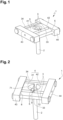
- the Figures 1 and 2 illustrate an embodiment 1 of the device according to the invention
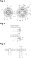
- the figure 3 illustrates another embodiment 1' of the device according to the invention
- the figures 6,7 , 8 and 9 illustrate yet another embodiment 1" of the device according to the invention.
- the device is reusable in the sense that, after having been used once to hold and then to release the transmission bar 2, 2' , it can again resume the holding configuration without it being necessary to "rearm" it manually.
- the transmission bar 2, 2' here designates any type of object intended to transmit a force or a holding force to an ancillary object 11, fixed to the transmission bar, and consequently fixed, via the transmission bar 2, 2', to the holding and releasing device 1, 1', 1" according to the invention.
- the device 1, 1', 1" according to the invention is thus a means of securing the ancillary object 11 to a part 12 of a main object, not shown in the figures, which carries the device 1, 1', 1" according to the invention and to which the device 1, 1', 1" according to the invention is securely attached.
- the main object may for example be a vehicle, a space vehicle, a satellite for example.
- the ancillary object 11 may be for example a solar generator 11 secured to a wall 12 of the vehicle.
- the ancillary object 11 may have to be held firmly on the vehicle, with a minimum of play and according to a maximum stress load undergone by the transmission bar and transmitted to the ancillary object 11, so that the ancillary object 11 is mechanically totally secured to the vehicle, during a phase of the implementation of the vehicle which carries the ancillary object 11, said phase being able, for example, to be a phase of launching a satellite; during this launch phase, a significant preload may be necessary to pass the vibrations which accompany this phase without play; during another phase of the implementation of the vehicle which carries the ancillary object 11, the ancillary object may have to be released, totally, or partially to introduce play, by reducing or canceling the stress load undergone by the transmission bar 2, 2' and transmitted to the ancillary object 11; This partial release can be
- the device 1, for holding and releasing a transmission bar 2 comprises a holding and releasing component 4, a clamping component 3, and a loosening component 5.
- the holding and releasing component 4 comprises a plurality of segments 41, 42, 43, 44.
- the segments 41 and 43 may for example be mechanically integral, to the point of forming only one piece; similarly, segments 42 and 44 may for example be mechanically integral, to the point of forming only one other piece.
- At least two segments 41, 42 of the plurality of segments 41, 42, 43, 44 which form the holding and releasing component 4, each comprise a bearing surface 71, 72 configured to bear on one end of the transmission bar 2; the end of the transmission bar 2 is thus kept pressed between said bearing surfaces 71, 72 of the at least two segments 41, 42, when the plurality of segments 41, 42, 43, 44, is in a holding configuration.
- the plurality of segments 41, 42, 43, 44, forming the holding and releasing component 4 is in the holding configuration under the effect of a clamping pressure generated by the clamping component 3.
- the clamping component 3 comprises at least one longitudinal element 33, 34, the at least one longitudinal element 33, 34 being securely attached by each end respectively to one 43 of the two segments 41, 43 and to one 44 of the other two segments 42, 44.
- the clamping component 3 is configured to exert said clamping pressure; thus, for example, said clamping component 3 can undergo elastic deformation, the clamping component 3 being made of a material capable of being elastically deformed to generate the clamping pressure necessary for maintaining the plurality of segments 41, 42, 43, 44 in the holding configuration.
- the elastic deformation is chosen, depending on the material considered, so that the clamping pressure is sufficient to ensure that the plurality of segments 41, 42, 43, 44 are held in the holding configuration, i.e. by exerting the necessary load on a part of the transmission bar 2.
- the clamping pressure is compensated by a release pressure exerted in the opposite direction by the release component 5;
- the release component can be made, for example, of a single-effect shape memory material, configured so that from a temperature of transition, the release pressure exerted by each end of the release component 5 on a bearing surface 8 of two other segments 43, 44, among the plurality of segments 41, 42, 43, 44, so as to compensate the clamping pressure and to spread the segments 43, 44, and cancel the load exerted by the segments 41 and 42 on the transmission bar 2;
- the plurality of segments 41, 42, 43, 44 assumes the release configuration, and releases the transmission bar 2.
- the material of the clamping component 3 is a conventional material, for example aluminum, or steel, and the additional deformation induced exceeds the elastic deformation threshold of said material, then the deformation is plastic and irreversible.
- manual resetting of the device will be necessary to return the device 1 to its holding configuration, in particular with the manual replacement of the deformed clamping component 3, which requires disassembly of the device.
- the device 1 configured with a clamping component made of conventional material makes it possible to switch from the holding configuration to the release configuration without shock, in particular without pyrotechnic or elastic shock.
- the clamping component 3 is then configured to naturally return to its initial position after having been elastically deformed by the separation of the 43 and 44 induced by the release pressure exerted by the release component 5, when this release pressure disappears. If the material of the clamping component 3 is not only elastic, but also superelastic, the extension of the reversible deformation may be greater. When the material of the clamping component 3 is elastic, or even superelastic, the device returns therefore naturally in its holding configuration when the release pressure exerted by the release component 5 disappears.
- the extension of the reversible deformation can be even much greater than with a superelastic material without shape memory.
- the superelastic material with shape memory can, for example, be chosen from the alloys of the following non-exhaustive list: NiTiCu, CuAlNi, CuAlBe, CuZnAl, FeMnAlNi.
- the device 1 is configured to alternately hold or release the end of the transmission bar 2, and in particular to return naturally, when the release pressure disappears, from the release configuration to the holding configuration, in other words the device is reversible, i.e. resettable, “in situ”.
- the release pressure disappears due to the stopping of the heating of the shape memory alloy release component which can then cool and return to its initial shape under the effect of or thanks to the elastic clamping element.
- the release component 5 may be made, at least in part, from a single-effect shape memory material, i.e. configured so that from a transition temperature, the release pressure exerted by each end of the release component 5 on the bearing surface 8 of the segments 43, 44 compensates for the tightening pressure of the tightening component 3. Since the material of the release component 5 has a shape memory, it returns to its initial shape naturally (two-way memory effect) or with the assistance of of the release element (assisted two-way memory effect) when the temperature returns to its initial temperature.
- the clamping component 3 assists the return of the at least one loosening component 5 to its initial shape.
- the clamping and loosening components can be merged into a single so-called clamping/loosening component which then provides both functions (tightening at low temperature and loosening at high temperature).
- the material of the clamping/loosening component is then a double-sided shape memory material which allows the component to return to its initial shape at low temperature without assistance.
- the clamping component comprises two longitudinal elements 33, 34, and the device comprises two longitudinal loosening components 5, each arranged parallel to one of the two longitudinal elements 33, 34 of the clamping component 3.
- the at least one loosening component 5 is longitudinal and arranged parallel to the longitudinal element 33, 34 of the tightening component 3.
- the device 1' comprises a clamping component 3' having the shape of a hollow cylinder around the plurality of segments 41', 42', 43', 44' of the holding and releasing component 4.
- the segments of the plurality of segments 41', 42', 43', 44' of the holding and releasing component 4 comprise a bearing surface 10 configured to bear on the clamping component 3, on the internal surface of the hollow cylinder.
- the release component 5 comprises four release components 51', 52', 53,' 54', i.e. one for each pair of segments of the holding and releasing component 4, each release component 51', 52', 53,' 54' being configured so that each of its ends bears respectively on a bearing surface 8' of a segment of the pair of segments associated with it.
- figure 3 shows, on the left of the figure, the device 1' in the holding configuration, the clamping component 3' holding the segments 41', 42', 43', 44' of the holding and releasing component 4 clamped against each other, by pressing radially on the bearing surface 10 of each of these segments.
- figure 3 shows, on the right of the figure, the device 1' in the release configuration, when each release component 51', 52', 53,'54' has been heated to a temperature greater than or equal to the end of transition temperature of the shape memory material constituting, at least in part, these release components.
- each release component 51', 52', 53,'54' on the pair of segments of the holding and release component 4 associated with it compensates for the clamping pressure of the clamping component 3' and separates the segments of each pair of segments of the holding and release component 4.
- the bearing surface 71, 72 of each segment of the plurality of segments 41', 42', 43', 44' of the holding and releasing component 4 is configured to take a conical or spherical or threaded or other bearing shape; with a conical bearing shape, when the device 1, 1' is in the holding configuration with the segments 41', 42', 43', 44' clamped against each other, the portion of the transmission bar 2 is held inside the conical bearing shape, as illustrated in the figure 4 .
- the held part for example, also has a shape, conical or spherical for example, complementary to the conical shape of the support surfaces 71, 72, then a configuration of partial release of said support shape can be defined, in which the load tension of the transmission bar 2 is reduced, as illustrated at the bottom of the figure. figure 4 .
- This configuration is particularly advantageous for reducing the preloads commonly installed in stacking columns or in bearings.
- this preload For bearings, it may be interesting to release this preload after a launch phase of a space vehicle on which a part secured via the transmission bar is mounted, a phase during which this preload must be kept high to pass the vibrations without play, while it is preferable to reduce this load during the following phases of the bearing's life to reduce the internal stresses, reduce the friction torques and thus extend the service life and allow a lighter motorization of the bearing.
- this makes it possible to reduce the stored elastic energy so as to reduce the shock generated during the sudden release of a stacking tie rod.
- the conical or cylindrical support shape of the support surface 71, 72 of each segment of the plurality of segments 41', 42', 43', 44' of the holding and releasing component 4 may be threaded, or provided with channels.
- the thread being configured to receive a complementary thread of the part of the transmission bar 2, or the channels being configured to receive a complementary shape of the part of the transmission bar 2
- the transmission bar 2 may be screwed into the device or gripped in the channels in the holding configuration, and released without unscrewing, as illustrated on the right part of the figure 5 .
- the invention relates to a holding system comprising a device 1, 1' as described above, and the transmission bar 2 held by the device 1, 1".
- the transmission bar 2 is a tie rod stressed in tension along an axis of the transmission bar 2, when the holding and release component 4 is in the holding configuration.
- the holding device 1" and of the holding system according to the invention will now be described with reference to the figures 6, 7 , 8 and 9 , in which the transmission bar 2 is movable and actuated in rotation about an axis of the transmission bar, between a first angular position and a second angular position, when the holding and release component 4 is in the release configuration.
- the device can serve as a stacking point during vibrations during the launch phase of the vehicle, when the holding and release component 4 is in the holding configuration, before switching to the release configuration, by heating the release component, for the deployment of an appendage 11, for example a solar panel 11, motorized for example by an additional spring 13, then locking in the deployed position at the end of deployment, the transmission bar being clamped again between the segments of the holding and release component, after cooling of the release component.
- the device 1bis comprises a clamping component 3 taking the form of at least one spring or at least one set of elastic washers, of the Belleville type.
- the holding and releasing component 4 comprises two segments 43, 44 which each comprise a first bearing surface 71, 72 configured to bear on the transmission bar 2, and a bearing surface, and a second bearing surface 8 configured to bear on one end of the at least one loosening component 51, 52.
- one of the segments 43 of the holding and releasing component is housed inside a cavity formed in the other segment 44 of the holding and releasing component, such that the spring(s) 3 or set(s) of elastic washers 3 are compressed between a face of the segment 43 and a face of the other segment 44 of the holding and releasing component, to hold the segment 43 and the other segment 44 of the holding and releasing component in the holding configuration.
- the release component(s) 51, 52 being configured to bear on the second bearing surface 8 located on the one hand on another face of the segment 43 and another face of the other segment 44 of the holding and releasing component.
Landscapes
- Engineering & Computer Science (AREA)
- General Engineering & Computer Science (AREA)
- Mechanical Engineering (AREA)
- Clamps And Clips (AREA)
- Pivots And Pivotal Connections (AREA)
- Jigs For Machine Tools (AREA)
- Remote Sensing (AREA)
- Aviation & Aerospace Engineering (AREA)
Applications Claiming Priority (2)
| Application Number | Priority Date | Filing Date | Title |
|---|---|---|---|
| FR2003837A FR3109413B1 (fr) | 2020-04-16 | 2020-04-16 | Dispositif de maintien et de libération à bas choc et réutilisable |
| PCT/FR2021/050668 WO2021209724A1 (fr) | 2020-04-16 | 2021-04-15 | Dispositif de maintien et de libération à bas choc et réutilisable |
Publications (3)
| Publication Number | Publication Date |
|---|---|
| EP4136357A1 EP4136357A1 (fr) | 2023-02-22 |
| EP4136357C0 EP4136357C0 (fr) | 2025-02-12 |
| EP4136357B1 true EP4136357B1 (fr) | 2025-02-12 |
Family
ID=72088226
Family Applications (1)
| Application Number | Title | Priority Date | Filing Date |
|---|---|---|---|
| EP21725574.4A Active EP4136357B1 (fr) | 2020-04-16 | 2021-04-15 | Dispositif de maintien et de libération à bas choc et réutilisable |
Country Status (7)
| Country | Link |
|---|---|
| US (1) | US12338846B2 (pl) |
| EP (1) | EP4136357B1 (pl) |
| JP (1) | JP7675100B2 (pl) |
| ES (1) | ES3025888T3 (pl) |
| FR (1) | FR3109413B1 (pl) |
| PL (1) | PL4136357T3 (pl) |
| WO (1) | WO2021209724A1 (pl) |
Family Cites Families (10)
| Publication number | Priority date | Publication date | Assignee | Title |
|---|---|---|---|---|
| US5160233A (en) * | 1992-05-13 | 1992-11-03 | The United State Of America As Representd By The Administrator Of The National Aeronautics And Space Administration | Fastening apparatus having shape memory alloy actuator |
| US5718561A (en) * | 1994-11-22 | 1998-02-17 | Siemens Aktiengesellschaft | Side channel compressor |
| US5718531A (en) * | 1996-01-22 | 1998-02-17 | Lockheed Martin Corporation | Low shock release device |
| US6126115A (en) * | 1997-01-21 | 2000-10-03 | Lockheed Martin Corporation | Apparatus for retaining and releasing a payload |
| DE19843965C2 (de) * | 1998-09-24 | 2000-07-13 | Daimler Chrysler Ag | Halte- und Auslösemechanismus mit einem Formgedächtnis-Aktuator |
| NZ544276A (en) * | 2003-06-26 | 2010-02-26 | Synthes Gmbh | Double jaws with an elastic closing action for distraction-compression apparatus |
| KR101120625B1 (ko) * | 2009-04-08 | 2012-03-13 | 한국항공대학교산학협력단 | 우주비행체의 부속물 분리장치 |
| CN106335653B (zh) * | 2016-09-21 | 2018-07-03 | 哈尔滨工业大学 | 一种形状记忆聚合物复合材料驱动的弹簧式分离机构 |
| CN109131951B (zh) * | 2018-09-03 | 2021-09-07 | 哈尔滨工业大学 | 一种由形状记忆合金sma丝束驱动的空间径向解锁机构 |
| CN109606737B (zh) * | 2018-12-29 | 2021-07-20 | 哈尔滨工业大学 | 一种锁紧释放与驱动旋转机构 |
-
2020
- 2020-04-16 FR FR2003837A patent/FR3109413B1/fr active Active
-
2021
- 2021-04-15 WO PCT/FR2021/050668 patent/WO2021209724A1/fr not_active Ceased
- 2021-04-15 JP JP2022562539A patent/JP7675100B2/ja active Active
- 2021-04-15 PL PL21725574.4T patent/PL4136357T3/pl unknown
- 2021-04-15 EP EP21725574.4A patent/EP4136357B1/fr active Active
- 2021-04-15 ES ES21725574T patent/ES3025888T3/es active Active
-
2022
- 2022-10-17 US US17/967,274 patent/US12338846B2/en active Active
Also Published As
| Publication number | Publication date |
|---|---|
| PL4136357T3 (pl) | 2025-08-04 |
| EP4136357A1 (fr) | 2023-02-22 |
| ES3025888T3 (en) | 2025-06-10 |
| JP7675100B2 (ja) | 2025-05-12 |
| WO2021209724A1 (fr) | 2021-10-21 |
| EP4136357C0 (fr) | 2025-02-12 |
| FR3109413B1 (fr) | 2022-03-18 |
| JP2023523571A (ja) | 2023-06-06 |
| US12338846B2 (en) | 2025-06-24 |
| FR3109413A1 (fr) | 2021-10-22 |
| US20230037250A1 (en) | 2023-02-02 |
Similar Documents
| Publication | Publication Date | Title |
|---|---|---|
| EP3027511B1 (fr) | Procédé et dispositif de liaison et de séparation de deux éléments, avec des plaques de liaison | |
| EP1342927B1 (fr) | Dispositif de fixation d'un élément sur une structure d'aéronef | |
| EP2319764A1 (fr) | Système de tirant actif permettant le maintien et la libération sans choc d'appendices spatiaux | |
| FR3022995A1 (fr) | Missile pourvu d'une coiffe de protection separable | |
| WO2000034094A1 (fr) | Dispositif de liaison mecanique deverrouillable pyrotechniquement | |
| EP3027510A1 (fr) | Procede et dispositif de liaison et de separation lineaire de deux elements, avec moyens energetiques decales | |
| EP0898551B1 (fr) | Systeme de blocage temporaire de deplacement de deux corps l'un par rapport a l'autre, suivant au moins un sens d'une direction predeterminee | |
| EP2904613B1 (fr) | Emballage pour le transport et/ou l'entreposage de matieres radioactives, comprenant des moyens ameliores de fixation d'un capot amortisseur de chocs | |
| EP0246958B1 (fr) | Dispositif de séparation pyrotechnique de deux éléments | |
| EP3396300B1 (fr) | Dispositif d'actionnement pour l'éjection d'au moins une partie amovible de missile, en particulier d'une coiffe | |
| EP3617075B1 (fr) | Dispositif de liaison localisee a separation commandee comprenant une couche de liaison multidirectionnelle | |
| EP4136357B1 (fr) | Dispositif de maintien et de libération à bas choc et réutilisable | |
| EP0488872B1 (fr) | Dispositif d'assujettissement temporaire d'un objet à un support à douille de retenue monobloc | |
| FR2734876A1 (fr) | Piece de liaison a absorption d'energie et siege d'aeronef equipe d'une telle piece | |
| EP3027512B1 (fr) | Procede et dispositif de liaison et de separation de deux elements avec des moyens de liaison et de separation melanges | |
| EP3344547A1 (fr) | Procede de liaison et de separation lineaire de deux elements | |
| FR2672673A1 (fr) | Dispositif d'amorcage pour un sous-projectile. | |
| EP0354088B1 (fr) | Dispositif d'ouverture d'empennage pour obus | |
| FR3063281A1 (fr) | Procede et dispositif de liaison et de separation lineaire de deux elements colles | |
| FR2716965A1 (fr) | Engin largable à stabilisation et freinage aérodynamique. | |
| EP0275766B1 (fr) | Dispositif de freinage du déploiement d'une aile, et projectile guidé équipé d'un tel dispositif | |
| EP2437025B1 (fr) | Système d'arme lance-munition à prolongateur tubulaire | |
| EP0546900A1 (fr) | Projectile équipé de pales élastiques | |
| FR2715721A1 (fr) | Obus gyrostabilisé de transport de charge utile. | |
| FR2942032A1 (fr) | Procede de fixation d'un projectile en matiere plastique sur un etui metallique et projectile permettant la mise en oeuvre de ce procede |
Legal Events
| Date | Code | Title | Description |
|---|---|---|---|
| STAA | Information on the status of an ep patent application or granted ep patent |
Free format text: STATUS: UNKNOWN |
|
| STAA | Information on the status of an ep patent application or granted ep patent |
Free format text: STATUS: THE INTERNATIONAL PUBLICATION HAS BEEN MADE |
|
| PUAI | Public reference made under article 153(3) epc to a published international application that has entered the european phase |
Free format text: ORIGINAL CODE: 0009012 |
|
| STAA | Information on the status of an ep patent application or granted ep patent |
Free format text: STATUS: REQUEST FOR EXAMINATION WAS MADE |
|
| 17P | Request for examination filed |
Effective date: 20221018 |
|
| AK | Designated contracting states |
Kind code of ref document: A1 Designated state(s): AL AT BE BG CH CY CZ DE DK EE ES FI FR GB GR HR HU IE IS IT LI LT LU LV MC MK MT NL NO PL PT RO RS SE SI SK SM TR |
|
| DAV | Request for validation of the european patent (deleted) | ||
| DAX | Request for extension of the european patent (deleted) | ||
| GRAP | Despatch of communication of intention to grant a patent |
Free format text: ORIGINAL CODE: EPIDOSNIGR1 |
|
| STAA | Information on the status of an ep patent application or granted ep patent |
Free format text: STATUS: GRANT OF PATENT IS INTENDED |
|
| INTG | Intention to grant announced |
Effective date: 20240903 |
|
| RIN1 | Information on inventor provided before grant (corrected) |
Inventor name: SICRE, JACQUES |
|
| GRAS | Grant fee paid |
Free format text: ORIGINAL CODE: EPIDOSNIGR3 |
|
| GRAA | (expected) grant |
Free format text: ORIGINAL CODE: 0009210 |
|
| STAA | Information on the status of an ep patent application or granted ep patent |
Free format text: STATUS: THE PATENT HAS BEEN GRANTED |
|
| AK | Designated contracting states |
Kind code of ref document: B1 Designated state(s): AL AT BE BG CH CY CZ DE DK EE ES FI FR GB GR HR HU IE IS IT LI LT LU LV MC MK MT NL NO PL PT RO RS SE SI SK SM TR |
|
| REG | Reference to a national code |
Ref country code: GB Ref legal event code: FG4D Free format text: NOT ENGLISH |
|
| REG | Reference to a national code |
Ref country code: CH Ref legal event code: EP |
|
| REG | Reference to a national code |
Ref country code: DE Ref legal event code: R096 Ref document number: 602021026001 Country of ref document: DE |
|
| REG | Reference to a national code |
Ref country code: IE Ref legal event code: FG4D Free format text: LANGUAGE OF EP DOCUMENT: FRENCH |
|
| U01 | Request for unitary effect filed |
Effective date: 20250310 |
|
| U07 | Unitary effect registered |
Designated state(s): AT BE BG DE DK EE FI FR IT LT LU LV MT NL PT RO SE SI Effective date: 20250317 |
|
| REG | Reference to a national code |
Ref country code: ES Ref legal event code: FG2A Ref document number: 3025888 Country of ref document: ES Kind code of ref document: T3 Effective date: 20250610 |
|
| U20 | Renewal fee for the european patent with unitary effect paid |
Year of fee payment: 5 Effective date: 20250522 |
|
| PG25 | Lapsed in a contracting state [announced via postgrant information from national office to epo] |
Ref country code: RS Free format text: LAPSE BECAUSE OF FAILURE TO SUBMIT A TRANSLATION OF THE DESCRIPTION OR TO PAY THE FEE WITHIN THE PRESCRIBED TIME-LIMIT Effective date: 20250512 |
|
| PGFP | Annual fee paid to national office [announced via postgrant information from national office to epo] |
Ref country code: GB Payment date: 20250418 Year of fee payment: 5 |
|
| PG25 | Lapsed in a contracting state [announced via postgrant information from national office to epo] |
Ref country code: IS Free format text: LAPSE BECAUSE OF FAILURE TO SUBMIT A TRANSLATION OF THE DESCRIPTION OR TO PAY THE FEE WITHIN THE PRESCRIBED TIME-LIMIT Effective date: 20250612 |
|
| PGFP | Annual fee paid to national office [announced via postgrant information from national office to epo] |
Ref country code: NO Payment date: 20250429 Year of fee payment: 5 |
|
| PG25 | Lapsed in a contracting state [announced via postgrant information from national office to epo] |
Ref country code: HR Free format text: LAPSE BECAUSE OF FAILURE TO SUBMIT A TRANSLATION OF THE DESCRIPTION OR TO PAY THE FEE WITHIN THE PRESCRIBED TIME-LIMIT Effective date: 20250212 |
|
| PG25 | Lapsed in a contracting state [announced via postgrant information from national office to epo] |
Ref country code: GR Free format text: LAPSE BECAUSE OF FAILURE TO SUBMIT A TRANSLATION OF THE DESCRIPTION OR TO PAY THE FEE WITHIN THE PRESCRIBED TIME-LIMIT Effective date: 20250513 |
|
| PGFP | Annual fee paid to national office [announced via postgrant information from national office to epo] |
Ref country code: CH Payment date: 20250501 Year of fee payment: 5 |
|
| PG25 | Lapsed in a contracting state [announced via postgrant information from national office to epo] |
Ref country code: SM Free format text: LAPSE BECAUSE OF FAILURE TO SUBMIT A TRANSLATION OF THE DESCRIPTION OR TO PAY THE FEE WITHIN THE PRESCRIBED TIME-LIMIT Effective date: 20250212 |
|
| PGFP | Annual fee paid to national office [announced via postgrant information from national office to epo] |
Ref country code: ES Payment date: 20250715 Year of fee payment: 5 |
|
| PGFP | Annual fee paid to national office [announced via postgrant information from national office to epo] |
Ref country code: PL Payment date: 20250403 Year of fee payment: 5 |
|
| PG25 | Lapsed in a contracting state [announced via postgrant information from national office to epo] |
Ref country code: CZ Free format text: LAPSE BECAUSE OF FAILURE TO SUBMIT A TRANSLATION OF THE DESCRIPTION OR TO PAY THE FEE WITHIN THE PRESCRIBED TIME-LIMIT Effective date: 20250212 |
|
| PG25 | Lapsed in a contracting state [announced via postgrant information from national office to epo] |
Ref country code: SK Free format text: LAPSE BECAUSE OF FAILURE TO SUBMIT A TRANSLATION OF THE DESCRIPTION OR TO PAY THE FEE WITHIN THE PRESCRIBED TIME-LIMIT Effective date: 20250212 |
|
| PLBE | No opposition filed within time limit |
Free format text: ORIGINAL CODE: 0009261 |
|
| STAA | Information on the status of an ep patent application or granted ep patent |
Free format text: STATUS: NO OPPOSITION FILED WITHIN TIME LIMIT |
|
| PG25 | Lapsed in a contracting state [announced via postgrant information from national office to epo] |
Ref country code: MC Free format text: LAPSE BECAUSE OF FAILURE TO SUBMIT A TRANSLATION OF THE DESCRIPTION OR TO PAY THE FEE WITHIN THE PRESCRIBED TIME-LIMIT Effective date: 20250212 |
|
| 26N | No opposition filed |
Effective date: 20251113 |