EP4136345B1 - Hebeanordnung für windturbine - Google Patents
Hebeanordnung für windturbine Download PDFInfo
- Publication number
- EP4136345B1 EP4136345B1 EP21721852.8A EP21721852A EP4136345B1 EP 4136345 B1 EP4136345 B1 EP 4136345B1 EP 21721852 A EP21721852 A EP 21721852A EP 4136345 B1 EP4136345 B1 EP 4136345B1
- Authority
- EP
- European Patent Office
- Prior art keywords
- lifting
- wind turbine
- nacelle
- tower
- lifting device
- Prior art date
- Legal status (The legal status is an assumption and is not a legal conclusion. Google has not performed a legal analysis and makes no representation as to the accuracy of the status listed.)
- Active
Links
Images

Classifications
-
- F—MECHANICAL ENGINEERING; LIGHTING; HEATING; WEAPONS; BLASTING
- F03—MACHINES OR ENGINES FOR LIQUIDS; WIND, SPRING, OR WEIGHT MOTORS; PRODUCING MECHANICAL POWER OR A REACTIVE PROPULSIVE THRUST, NOT OTHERWISE PROVIDED FOR
- F03D—WIND MOTORS
- F03D13/00—Assembly, mounting or commissioning of wind motors; Arrangements specially adapted for transporting wind motor components
- F03D13/10—Assembly of wind motors; Arrangements for erecting wind motors
-
- B—PERFORMING OPERATIONS; TRANSPORTING
- B66—HOISTING; LIFTING; HAULING
- B66C—CRANES; LOAD-ENGAGING ELEMENTS OR DEVICES FOR CRANES, CAPSTANS, WINCHES, OR TACKLES
- B66C23/00—Cranes comprising essentially a beam, boom, or triangular structure acting as a cantilever and mounted for translatory of swinging movements in vertical or horizontal planes or a combination of such movements, e.g. jib-cranes, derricks, tower cranes
- B66C23/18—Cranes comprising essentially a beam, boom, or triangular structure acting as a cantilever and mounted for translatory of swinging movements in vertical or horizontal planes or a combination of such movements, e.g. jib-cranes, derricks, tower cranes specially adapted for use in particular purposes
- B66C23/20—Cranes comprising essentially a beam, boom, or triangular structure acting as a cantilever and mounted for translatory of swinging movements in vertical or horizontal planes or a combination of such movements, e.g. jib-cranes, derricks, tower cranes specially adapted for use in particular purposes with supporting couples provided by walls of buildings or like structures
- B66C23/207—Cranes comprising essentially a beam, boom, or triangular structure acting as a cantilever and mounted for translatory of swinging movements in vertical or horizontal planes or a combination of such movements, e.g. jib-cranes, derricks, tower cranes specially adapted for use in particular purposes with supporting couples provided by walls of buildings or like structures with supporting couples provided by wind turbines
-
- F—MECHANICAL ENGINEERING; LIGHTING; HEATING; WEAPONS; BLASTING
- F03—MACHINES OR ENGINES FOR LIQUIDS; WIND, SPRING, OR WEIGHT MOTORS; PRODUCING MECHANICAL POWER OR A REACTIVE PROPULSIVE THRUST, NOT OTHERWISE PROVIDED FOR
- F03D—WIND MOTORS
- F03D13/00—Assembly, mounting or commissioning of wind motors; Arrangements specially adapted for transporting wind motor components
- F03D13/20—Arrangements for mounting or supporting wind motors; Masts or towers for wind motors
-
- F—MECHANICAL ENGINEERING; LIGHTING; HEATING; WEAPONS; BLASTING
- F03—MACHINES OR ENGINES FOR LIQUIDS; WIND, SPRING, OR WEIGHT MOTORS; PRODUCING MECHANICAL POWER OR A REACTIVE PROPULSIVE THRUST, NOT OTHERWISE PROVIDED FOR
- F03D—WIND MOTORS
- F03D80/00—Details, components or accessories not provided for in groups F03D1/00 - F03D17/00
- F03D80/50—Maintenance or repair
-
- F—MECHANICAL ENGINEERING; LIGHTING; HEATING; WEAPONS; BLASTING
- F05—INDEXING SCHEMES RELATING TO ENGINES OR PUMPS IN VARIOUS SUBCLASSES OF CLASSES F01-F04
- F05B—INDEXING SCHEME RELATING TO WIND, SPRING, WEIGHT, INERTIA OR LIKE MOTORS, TO MACHINES OR ENGINES FOR LIQUIDS COVERED BY SUBCLASSES F03B, F03D AND F03G
- F05B2230/00—Manufacture
- F05B2230/60—Assembly methods
- F05B2230/61—Assembly methods using auxiliary equipment for lifting or holding
-
- F—MECHANICAL ENGINEERING; LIGHTING; HEATING; WEAPONS; BLASTING
- F05—INDEXING SCHEMES RELATING TO ENGINES OR PUMPS IN VARIOUS SUBCLASSES OF CLASSES F01-F04
- F05B—INDEXING SCHEME RELATING TO WIND, SPRING, WEIGHT, INERTIA OR LIKE MOTORS, TO MACHINES OR ENGINES FOR LIQUIDS COVERED BY SUBCLASSES F03B, F03D AND F03G
- F05B2240/00—Components
- F05B2240/10—Stators
- F05B2240/14—Casings, housings, nacelles, gondels or the like, protecting or supporting assemblies there within
-
- F—MECHANICAL ENGINEERING; LIGHTING; HEATING; WEAPONS; BLASTING
- F05—INDEXING SCHEMES RELATING TO ENGINES OR PUMPS IN VARIOUS SUBCLASSES OF CLASSES F01-F04
- F05B—INDEXING SCHEME RELATING TO WIND, SPRING, WEIGHT, INERTIA OR LIKE MOTORS, TO MACHINES OR ENGINES FOR LIQUIDS COVERED BY SUBCLASSES F03B, F03D AND F03G
- F05B2240/00—Components
- F05B2240/90—Mounting on supporting structures or systems
- F05B2240/91—Mounting on supporting structures or systems on a stationary structure
- F05B2240/916—Mounting on supporting structures or systems on a stationary structure with provision for hoisting onto the structure
-
- F—MECHANICAL ENGINEERING; LIGHTING; HEATING; WEAPONS; BLASTING
- F05—INDEXING SCHEMES RELATING TO ENGINES OR PUMPS IN VARIOUS SUBCLASSES OF CLASSES F01-F04
- F05D—INDEXING SCHEME FOR ASPECTS RELATING TO NON-POSITIVE-DISPLACEMENT MACHINES OR ENGINES, GAS-TURBINES OR JET-PROPULSION PLANTS
- F05D2230/00—Manufacture
- F05D2230/60—Assembly methods
- F05D2230/68—Assembly methods using auxiliary equipment for lifting or holding
-
- Y—GENERAL TAGGING OF NEW TECHNOLOGICAL DEVELOPMENTS; GENERAL TAGGING OF CROSS-SECTIONAL TECHNOLOGIES SPANNING OVER SEVERAL SECTIONS OF THE IPC; TECHNICAL SUBJECTS COVERED BY FORMER USPC CROSS-REFERENCE ART COLLECTIONS [XRACs] AND DIGESTS
- Y02—TECHNOLOGIES OR APPLICATIONS FOR MITIGATION OR ADAPTATION AGAINST CLIMATE CHANGE
- Y02E—REDUCTION OF GREENHOUSE GAS [GHG] EMISSIONS, RELATED TO ENERGY GENERATION, TRANSMISSION OR DISTRIBUTION
- Y02E10/00—Energy generation through renewable energy sources
- Y02E10/70—Wind energy
- Y02E10/72—Wind turbines with rotation axis in wind direction
-
- Y—GENERAL TAGGING OF NEW TECHNOLOGICAL DEVELOPMENTS; GENERAL TAGGING OF CROSS-SECTIONAL TECHNOLOGIES SPANNING OVER SEVERAL SECTIONS OF THE IPC; TECHNICAL SUBJECTS COVERED BY FORMER USPC CROSS-REFERENCE ART COLLECTIONS [XRACs] AND DIGESTS
- Y02—TECHNOLOGIES OR APPLICATIONS FOR MITIGATION OR ADAPTATION AGAINST CLIMATE CHANGE
- Y02E—REDUCTION OF GREENHOUSE GAS [GHG] EMISSIONS, RELATED TO ENERGY GENERATION, TRANSMISSION OR DISTRIBUTION
- Y02E10/00—Energy generation through renewable energy sources
- Y02E10/70—Wind energy
- Y02E10/728—Onshore wind turbines
-
- Y—GENERAL TAGGING OF NEW TECHNOLOGICAL DEVELOPMENTS; GENERAL TAGGING OF CROSS-SECTIONAL TECHNOLOGIES SPANNING OVER SEVERAL SECTIONS OF THE IPC; TECHNICAL SUBJECTS COVERED BY FORMER USPC CROSS-REFERENCE ART COLLECTIONS [XRACs] AND DIGESTS
- Y02—TECHNOLOGIES OR APPLICATIONS FOR MITIGATION OR ADAPTATION AGAINST CLIMATE CHANGE
- Y02P—CLIMATE CHANGE MITIGATION TECHNOLOGIES IN THE PRODUCTION OR PROCESSING OF GOODS
- Y02P70/00—Climate change mitigation technologies in the production process for final industrial or consumer products
- Y02P70/50—Manufacturing or production processes characterised by the final manufactured product
Definitions
- the invention relates to a wind turbine lifting arrangement.
- a lifting device such as a crane, is necessary to lift the heavy components, such as a generator or a gearbox, of the wind turbine into or out of the nacelle.
- the lifting device is placed on top or inside of the nacelle and on a top section of the tower.
- the lifting device is typically unavoidable to loosen bolted joints of the nacelle.
- the bolted joints are safety-relevant and thus the loosening of these bolted joints should be avoided.
- the lifting device placed on top or inside of the nacelle requires or at least obstructs assembly space within the nacelle. Therefore, the operation of the lifting device is typically limited in regard to the components which may be reached and lifted and the movability of the lifting device.
- a lifting platform having the lifting device is attached to the tower.
- To attach the lifting platform to the tower it is known to provide the lifting platform with grippers for gripping the tower. Thereby, large gripping forces are applied to the tower possibly damaging the tower. Further, the lifting device when operated applies very large compressive loads to the top section of the tower, which may result in a damage to the tower and should be avoided. Also, such a lifting platform is expensive and rather difficult to operate.
- US 2018/0335023 A1 describes a nacelle component for a nacelle of a wind turbine having a rotor shaft having a rotational axis.
- the nacelle component comprises a mainframe module and a power electronics module.
- the nacelle component has an assembled state wherein said power electronics module is mounted to said mainframe module with a longitudinal axis of said mainframe module being oriented parallel to the rotational axis of the rotor shaft.
- the longitudinal axis of said power electronics module intersects with a vertical plane that is parallel to the longitudinal axis of said mainframe module.
- WO 2019/042506 A1 describes a wind turbine comprising a tower, a nacelle mounted on the tower, and a movable container mounted on a lower part of the nacelle.
- the movable container is housing a hoisting mechanism for hoisting and/or lowering the movable container and for hoisting and/or lowering wind turbine components.
- US 2008/0257844 A1 describes an independent mobile crane system for temporarily use for moving or replacement of components during service operations and during erection of wind turbine generators comprising an auxiliary gantry crane forming a gantry frame conformed to rotate around the nacelle according to a rotation axis.
- the independent mobile crane system has a hoisting device integrated in the crane system arranged to allow the crane system to be self-hoisting, in that the independent mobile crane system docks to the nacelle via a docking unit and in that the independent mobile crane system is arranged to operate above the nacelle and on the outside of the nacelle sides. Further prior art is disclosed in CN 202529738 U .
- a wind turbine lifting arrangement comprising a tower of a wind turbine, a nacelle of the wind turbine being, a lifting platform and a lifting device attached to the lifting platform for lifting components of the wind turbine to be installed in the nacelle or deinstalled from the nacelle.
- the nacelle comprises a main frame attached to a top section of the tower.
- An attachment portion of the lifting platform is arranged underneath the nacelle and attached to the main frame.
- the lifting platform comprises a lifting device portion provided adjacent to the attachment portion.
- the lifting device is attached to the lifting platform in the lifting device portion.
- the lifting device portion and the lifting device are arranged next to a longitudinal side of the nacelle.
- the longitudinal side of the nacelle is one of two opposite longitudinal sides of the nacelle extending along a longitudinal axis of the nacelle and arranged between a top side and bottom side of the nacelle. Furthermore, the lifting platform extends along its longitudinal axis in a direction transverse to the longitudinal axis of the nacelle.
- the lifting platform By attaching the lifting platform with is attachment portion underneath the nacelle to the main frame of the nacelle, the bending loads applied to the lifting platform due to operation of the lifting device are transferred to the main frame rather than the tower, whereby the tower is prevented from damage. Further, on the lifting platform, the lifting device is free to move and may be operated with ease. Also, the lifting platform may be easily attached to and detached from the main frame and consecutively the lifting device may be easily attached to the lifting platform. Thereby, in the wind turbine lifting arrangement of the invention, the lifting device is easy to install on the lifting platform attached to the main frame of the nacelle, is operable with ease and high movability and is not applying possibly damaging loads to the tower.
- the lifting device is arranged next to a longitudinal side of the nacelle. That the lifting device is arranged next to the longitudinal side of the nacelle in particular means that it is arranged opposite of that longitudinal side or, in other words, faces the longitudinal side.
- the nacelle comprises two opposites longitudinal sides as sides in between the top side and the bottom side of the nacelle and extending along the longitudinal axis of the nacelle.
- the longitudinal sides are located opposite from one another on the nacelle. Further, they may be arranged parallel to one another.
- the lifting device is provided with a particularly high mobility and may access and lift all components in the nacelle.
- the lifting platform extends away with its lifting device portion from the bottom side of the nacelle, where it may be attached with its attachment portion to the main frame.
- the lifting device may be supported or, in other words, rested on top of the lifting device portion of the lifting platform.
- the lifting device portion thereby may only be the portion of the lifting platform which extends out of the plane of the nacelle or, in other words, away from the nacelle.
- the lifting device portion may have an extension of at least 0.5 m, in particular of at least 1 m or at least 2 m, for example. The extension thereby may be such that the lifting device may be safely rested and secured with its dimensions on top of the lifting device portion of the lifting platform.
- That the lifting platform is arranged underneath the nacelle in particular means that the lifting platform is arranged at the bottom side of the nacelle.
- the bottom side of the nacelle is the side facing the ground when the nacelle is supported on the tower.
- the lifting platform may thereby be arranged facing the tower.
- the lifting device portion may be extending along the longitudinal axis of the lifting platform.
- the lifting platform, in particular its lifting device portion may generally have a plate shape.
- the lifting device may be supported on top of the lifting device portion or, in other words, rest on the lifting device portion.
- the lifting platform extends along its longitudinal axis in a direction perpendicular to the longitudinal axis of the nacelle.
- the lifting platform may be attached to the main frame along the entire width of the nacelle such that a very secure attachment is provided.
- the lifting device portion comprises a carriage for the lifting device.
- the carriage is configured slidable such that the lifting device can be moved along the lifting platform and closer to or further away from the nacelle. Thereby, the lifting device can be positioned optimally with respect to the nacelle.
- the lifting platform comprises two beams attached to the main frame.
- the beams give structural support to the lifting platform and may be easily attached to the main frame by means of bolted joints, for example.
- the beams may be designed as I-beams, for example.
- the two beams are arranged parallel to one another. Thereby, even distribution of bending loads from the lifting device along the two beams of the lifting platform and the main frame may be achieved.
- the lifting device is attached to a carrying structure of the lifting platform connecting the two beams with each other.
- the carrying structure is secured to the two beams and allows for carrying the weight and bending loads of the lifting device to the main frame via the two beams.
- the carrying structure may comprise the lifting device portion and/or the attachment portion of the lifting platform.
- the carrying structure is designed as a carrying plate.
- the design of the lifting platform is thin and lightweight.
- the lifting platform comprises a support structure arranged underneath the lifting device, the support structure extending parallel to the tower and the support structure being arranged to be pressed against the tower when the lifting device is loaded with a component of the wind turbine.
- the support structure prevents that excessive bending loads are applied to the lifting platform and transferred therefrom to the main frame which may be harmful to the lifting platform and the main frame. Instead, a portion of the bending loads introduced into the lifting platform, when the lifting device is loaded and rotated, is shifted to the tower.
- these are not applied to the top portion of the tower but instead, in particular evenly, distributed at an upper portion of the tower along the length of the tower by means of the support structure due to its extension along the tower.
- the top portion of the tower has the top side of the tower whereas the upper portion is a portion of the tower next to the top portion and extending downwards along the tower but not having the top portion, i.e. the top side.
- the support structure may be attached to the lifting platform, in particular the two beams, and/or to the lifting device.
- the support structure may be arranged resting on the tower, in particular on the upper portion of the tower.
- the support structure has a concave side corresponding to and facing a rounded shape of the tower.
- the concave side of the support structure is forced against the rounded shape of the tower when the support structure is pressed against the tower when the lifting device is loaded and rotated with a component of the wind turbine.
- the support structure may in particular be arranged to form-fit with its concave side to the tower. The portion of bending loads shifted to the support structure may therefore be transferred to the tower in a particular even manner.
- the support structure is designed as an elongate body.
- the elongate body may be a cylinder.
- the support structure may distribute the portion of the bending loads over a large length of the tower.
- the attachment portion of the lifting platform is arranged at or within 5 m distance, in particular within 2 m distance, to the tower. Thereby the path of the bending loads from the lifting platform via the main frame to the tower is kept small and possible damage of the tower is prevented.
- FIGURES 1 to 4 embodiments of the present invention are described in detail.
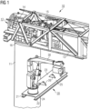
- FIGURE 1 shows a side perspective view on the operation of installing a lifting device 30 at a wind turbine 10 to be installed.
- the wind turbine 10 comprises a tower 11 and a nacelle 12.
- the nacelle 12 has a main frame 13 as a structure supporting components 14, 15 of the wind turbine 10 inside of the nacelle 12 and resting on a top side of a top portion 16 of the tower 11.
- the components 14, 15 exemplary denominated inside the nacelle 12 are a main shaft 14 and a gearbox 15.
- a lifting platform 20 carrying the lifting device 30 is to be arranged underneath the nacelle 12 or main frame 13 or, in other words, on a bottom side of the nacelle 12.
- the lifting platform 20 comprises two eyelets 26 for lifting the lifting platform 20 towards the nacelle 12, where the lifting platform 20 may be attached to the bottom side of the nacelle 12, i.e. to the main frame 13.
- the lifting platform 20 may be attached to the main frame 13 by means of bolted joints, for example.
- the lifting platform 20 comprises two beams 21, 22.
- the beams 21, 22 are arranged parallel to one another and connected with each other by means of a carrying structure 24.
- the carrying structure 23 has the two eyelets 26 on a top side thereof.
- the carrying structure 23 is designed as a carrying plate.
- the carrying structure 23 comprises an attachment portion 25 for attachment to the main frame 13.
- the attachment portion 25 is covered by the nacelle 12 when looked from the top and down to the nacelle 12 and the lifting platform 20, as can be seen in FIG. 2 .
- the carrying structure 23 comprises a lifting device portion 24, in which the lifting device 30 is installed.
- the lifting device 30 may be installed after lifting the lifting platform 20 first and consecutively lifting the lifting device 30 second, for example by means of an auxiliary lifting device (not shown) installed on the nacelle 12.
- the auxiliary lifting device may be smaller in size and lighter in weight such that it may not be able to lift the heavy components 14, 15 of the wind turbine 10 but the lifting platform 20 and the lifting device 30, which may be larger in size and heavier such that it may be able to lift the heavy components 14, 15 of the wind turbine 10.
- the lifting device 30 When the lifting device 30 is lifted to the lifting platform 20, the lifting device 30 is installed in the lifting device section 24 of the lifting platform 20.
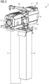
- FIGURE 2 shows a side perspective view on a wind turbine lifting arrangement 1 according to a first embodiment of the invention as installed according to FIG. 1 .
- the lifting device 30 is installed on the lifting platform 20 such that the lifting device 30 is arranged next to a longitudinal side 19 of the nacelle 12.
- the longitudinal side 19 is a side transverse, in particular perpendicular, to the top side 17 and/or bottom side 18 of the nacelle 12 and/or ground.
- the lifting platform 20 extends with its lifting device portion 24 from underneath the nacelle 12 along its longitudinal axis L 20 traverse to the nacelle 12.
- an angle ⁇ is formed between the longitudinal axis L 20 of the lifting platform 20 and the longitudinal axis L 12 of the nacelle 12.
- the angle ⁇ may be in the range of 80 ° to 100 °, in particular 85 ° to 95 °, for example. In this case, the angle ⁇ is 90 ° so that the lifting platform 20 is arranged perpendicular to the nacelle 12.
- the lifting device 30 is shown lifting a component 15 of the wind turbine 10, in this case the gearbox 15. This may be done for installing the gearbox 15 inside of the nacelle 12 or removing it therefrom for replacement or service.
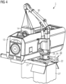
- FIGURE 3 shows a side perspective view on a wind turbine lifting arrangement 1 according to a second embodiment of the invention.
- a support structure 27 is arranged underneath the lifting device 30.
- the support structure 27 is designed as an elongate weighted body and extends along its longitudinal extension in parallel to an upper section of the tower 11.
- the support structure 27 is arranged next to the tower 11 or in contact with the tower 11 such that it is pressed against the tower 11 when the lifting device 30 is loaded with a component 14, 15 of the wind turbine 10. Thereby, the bending loads applied to the lifting platform 20 due to operation of the lifting device 30 are in part shifted to the support structure 27 transferring them to the tower 11.
- the support structure 27 has a concave side corresponding to and facing the rounded shape of the tower 11. However, the concave side is covered by the support structure 27 in this perspective.
- FIGURE 4 shows a detailed side perspective view on the wind turbine lifting arrangement 1 of FIG. 3 in operation of its lifting device 30.
- the lifting device 30 is lifting a component 14 of the wind turbine 1, which may be the main shaft 14.
Landscapes
- Engineering & Computer Science (AREA)
- Mechanical Engineering (AREA)
- Life Sciences & Earth Sciences (AREA)
- Sustainable Development (AREA)
- Sustainable Energy (AREA)
- Chemical & Material Sciences (AREA)
- Combustion & Propulsion (AREA)
- General Engineering & Computer Science (AREA)
- Civil Engineering (AREA)
- Structural Engineering (AREA)
- Wind Motors (AREA)
Claims (15)
- Windturbinenhebeanordnung (1), umfassend einen Turm (11) einer Windturbine (10), eine Gondel (12) der Windturbine (10), eine Hebeplattform (20) und eine an der Hebeplattform (20) befestigte Hebevorrichtung (30) zum Heben von Komponenten (14, 15) der Windturbine (10), die in der Gondel (12) eingebaut oder aus der Gondel (12) ausgebaut werden sollen,wobei die Gondel (12) einen Hauptrahmen (13) umfasst, der an einem oberen Abschnitt (16) des Turms (11) befestigt ist,wobei die Hebeplattform (20) einen Befestigungsteil (25) und einen Hebevorrichtungsteil (24) umfasst, wobei der Befestigungsteil (25) unter der Gondel (12) angeordnet ist und am Hauptrahmen (13) befestigt ist, und wobei der Hebevorrichtungsteil (24) angrenzend an den Befestigungsteil (25) bereitgestellt ist,wobei die Hebevorrichtung (30) in dem Hebevorrichtungsteil (24) an der Hebeplattform (20) befestigt ist, undwobei der Hebevorrichtungsteil (24) und die Hebevorrichtung (30) neben einer längs verlaufenden Seite (19) der Gondel (12) angeordnet sind, wobei die längs verlaufende Seite (19) der Gondel (12) eine von zwei einander gegenüberliegenden längs verlaufenden Seiten (19) der Gondel (12) ist, die sich entlang einer Längsachse (L12) der Gondel (12) erstrecken und zwischen einer oberen Seite (17) und einer unteren Seite (18) der Gondel (12) angeordnet sind, undwobei sich die Hebeplattform (20) entlang ihrer Längsachse (L20) in eine Richtung quer zur Längsachse (L12) der Gondel (12) erstreckt.
- Windturbinenhebeanordnung (1) nach Anspruch 1, wobei ein Winkel α zwischen der Längsachse (L20) der Hebeplattform (20) und der Längsachse (L12) der Gondel (12) im Bereich von 80° bis 100°, insbesondere von 85° bis 95°, ist.
- Windturbinenhebeanordnung (1) nach Anspruch 1 oder 2, wobei sich die Hebeplattform (20) entlang ihrer Längsachse (L20) in eine Richtung senkrecht zur Längsachse (L12) der Gondel (12) erstreckt.
- Windturbinenhebeanordnung (1) nach einem der vorhergehenden Ansprüche, wobei der Hebevorrichtungsteil (24) einen Schlitten für die Hebevorrichtung (30) umfasst.
- Windturbinenhebeanordnung (1) nach Anspruch 4, wobei der Schlitten gleitbar ausgelegt ist, sodass die Hebevorrichtung (30) entlang der Hebeplattform (20) und näher zu oder weiter weg von der Gondel (12) bewegt werden kann.
- Windturbinenhebeanordnung (1) nach einem der vorhergehenden Ansprüche, wobei die Hebeplattform (20) zwei Träger (21, 22) umfasst, die am Hauptrahmen (13) befestigt sind.
- Windturbinenhebeanordnung (1) nach Anspruch 6, wobei die zwei Träger (21, 22) parallel zueinander angeordnet sind.
- Windturbinenhebeanordnung (1) nach Anspruch 6 oder 7, wobei die Hebevorrichtung (30) an einer Tragestruktur (23) der Hebeplattform (20) befestigt ist, die die zwei Träger (21, 22) miteinander verbindet.
- Windturbinenhebeanordnung (1) nach Anspruch 8, wobei die Tragestruktur (23) als eine Trageplatte ausgestaltet ist.
- Windturbinenhebeanordnung (1) nach einem der vorhergehenden Ansprüche, wobei die Hebeplattform (20) eine Stützstruktur (27) umfasst, die unter der Hebevorrichtung (30) angeordnet ist, wobei sich die Stützstruktur (27) parallel zum Turm (11) erstreckt und angeordnet ist, um gegen den Turm (11) gepresst zu werden, wenn die Hebevorrichtung (30) mit einer Komponente (14, 15) der Windturbine (10) beladen ist.
- Windturbinenhebeanordnung (1) nach Anspruch 10, wobei die Stützstruktur (27) eine konkave Seite aufweist, die einer gerundeten Form des Turms (11) entspricht und zu dieser zeigt.
- Windturbinenhebeanordnung (1) nach Anspruch 10 oder 11, wobei die Stützstruktur (27) so ausgelegt ist, dass ein Teil der Biegelasten, die in die Hebeplattform (20) eingebracht werden, wenn die Hebevorrichtung (30) beladen und gedreht wird, auf den Turm (11) verlagert wird.
- Windturbinenhebeanordnung (1) nach Anspruch 12, wobei die Stützstruktur (27) so ausgelegt ist, dass die Biegelasten nicht auf den oberen Teil des Turms (11) angewendet werden, sondern, stattdessen, insbesondere gleichmäßig auf einen oberen Teil des Turms (11) entlang der Länge des Turms (11) mittels der Stützstruktur (27) aufgrund ihrer Ausdehnung entlang des Turms (11) verteilt werden.
- Windturbinenhebeanordnung (1) nach einem der Ansprüche 10 bis 13, wobei die Stützstruktur (27) als ein länglicher Körper ausgestaltet ist.
- Windturbinenhebeanordnung nach einem der vorhergehenden Ansprüche, wobei der Befestigungsteil (25) der Hebeplattform (20) am oder innerhalb eines Abstands von 5 m zum Turm (11) angeordnet ist.
Applications Claiming Priority (2)
| Application Number | Priority Date | Filing Date | Title |
|---|---|---|---|
| EP20382306.7A EP3896280A1 (de) | 2020-04-16 | 2020-04-16 | Hebeanordnung für windturbine |
| PCT/EP2021/059366 WO2021209350A1 (en) | 2020-04-16 | 2021-04-12 | Wind turbine lifting arrangement |
Publications (2)
| Publication Number | Publication Date |
|---|---|
| EP4136345A1 EP4136345A1 (de) | 2023-02-22 |
| EP4136345B1 true EP4136345B1 (de) | 2024-06-26 |
Family
ID=70391040
Family Applications (2)
| Application Number | Title | Priority Date | Filing Date |
|---|---|---|---|
| EP20382306.7A Withdrawn EP3896280A1 (de) | 2020-04-16 | 2020-04-16 | Hebeanordnung für windturbine |
| EP21721852.8A Active EP4136345B1 (de) | 2020-04-16 | 2021-04-12 | Hebeanordnung für windturbine |
Family Applications Before (1)
| Application Number | Title | Priority Date | Filing Date |
|---|---|---|---|
| EP20382306.7A Withdrawn EP3896280A1 (de) | 2020-04-16 | 2020-04-16 | Hebeanordnung für windturbine |
Country Status (7)
| Country | Link |
|---|---|
| US (1) | US12545557B2 (de) |
| EP (2) | EP3896280A1 (de) |
| CN (1) | CN115335599B (de) |
| DK (1) | DK4136345T3 (de) |
| ES (1) | ES2988742T3 (de) |
| PL (1) | PL4136345T3 (de) |
| WO (1) | WO2021209350A1 (de) |
Family Cites Families (8)
| Publication number | Priority date | Publication date | Assignee | Title |
|---|---|---|---|---|
| ES2246163B1 (es) * | 2004-07-23 | 2007-03-16 | Gamesa Eolica, S.A. Sociedad Unipersonal | Un sistema de grua movil independiente de uso temporal para mover o reemplazar componentes y para el montaje de aerogeneradores. |
| US8922038B2 (en) * | 2010-12-08 | 2014-12-30 | Northern Power Systems, Inc. | Wind power unit having an underslung transformer |
| EP2505541B1 (de) * | 2011-03-31 | 2016-11-30 | ALSTOM Renewable Technologies | Windturbine |
| CN202529738U (zh) * | 2012-03-06 | 2012-11-14 | 华电郑州机械设计研究院有限公司 | 风电专用吊机 |
| DE102017004800A1 (de) * | 2017-05-18 | 2018-11-22 | Senvion Gmbh | Gondelkomponente für eine Windenergieanlage und Verfahren zum Montieren einer Gondelkomponente |
| WO2019042506A1 (en) * | 2017-08-29 | 2019-03-07 | Vestas Wind Systems A/S | WIND TURBINE WITH A MOBILE CONTAINER HAVING A LIFTING MECHANISM |
| EP3632833A1 (de) * | 2018-10-02 | 2020-04-08 | S&L Access Systems AB | Hubanordnung für eine windturbine |
| DK180818B1 (en) * | 2019-05-21 | 2022-04-26 | Liftra Ip Aps | Wind turbine tower with crane connecting elements and a crane with tower flange connecting elements |
-
2020
- 2020-04-16 EP EP20382306.7A patent/EP3896280A1/de not_active Withdrawn
-
2021
- 2021-04-12 PL PL21721852.8T patent/PL4136345T3/pl unknown
- 2021-04-12 CN CN202180028596.4A patent/CN115335599B/zh active Active
- 2021-04-12 WO PCT/EP2021/059366 patent/WO2021209350A1/en not_active Ceased
- 2021-04-12 DK DK21721852.8T patent/DK4136345T3/da active
- 2021-04-12 EP EP21721852.8A patent/EP4136345B1/de active Active
- 2021-04-12 ES ES21721852T patent/ES2988742T3/es active Active
- 2021-04-12 US US17/918,527 patent/US12545557B2/en active Active
Also Published As
| Publication number | Publication date |
|---|---|
| EP3896280A1 (de) | 2021-10-20 |
| DK4136345T3 (da) | 2024-08-26 |
| ES2988742T3 (es) | 2024-11-21 |
| CN115335599A (zh) | 2022-11-11 |
| WO2021209350A1 (en) | 2021-10-21 |
| US20230159309A1 (en) | 2023-05-25 |
| EP4136345A1 (de) | 2023-02-22 |
| CN115335599B (zh) | 2025-12-23 |
| US12545557B2 (en) | 2026-02-10 |
| PL4136345T3 (pl) | 2024-10-14 |
Similar Documents
| Publication | Publication Date | Title |
|---|---|---|
| EP3144524B1 (de) | Handhabungssystem für eine windturbinengondel, verfahren für transport und vertikales verschieben einer windturbinengondel | |
| EP1668244B1 (de) | Ausrüstung zur anbringung an der nabe einer windturbine und verfahren zur durchführung von wartungsarbeiten an einer windturbine unter verwendung von solcher ausrüstung | |
| CN102951548B (zh) | 一种用于装卸风力发电机转子叶片的装置以及方法 | |
| CN110944928B (zh) | 用于将部件提升到风力涡轮机的升降组件及其使用方法 | |
| EP2224126A2 (de) | Verfahren zur Handhabung des Rotorblatts einer Windenergieanlage in eine vertikale Position | |
| US12305613B2 (en) | Method and blade installation device for installing a blade of an offshore wind turbine | |
| CN112938789B (zh) | 用于架设塔架的起重机及方法 | |
| CN102187090A (zh) | 用于风力涡轮机的维护起重机 | |
| EP3311024B1 (de) | Tragbare und modulare hebeanordnung für eine windturbine | |
| CN116848320A (zh) | 用于机舱的滑动顶部系统 | |
| KR20230159511A (ko) | 작업 점검 설비 및 방법 | |
| EP4136345B1 (de) | Hebeanordnung für windturbine | |
| EP3728098A1 (de) | Verfahren zur handhabung einer windturbinenkomponente und einer windturbine mit einem kran | |
| EP3676493B1 (de) | Windturbine mit einem transportsystem zum bewegen von antriebsstrangkomponenten | |
| EP4290073B1 (de) | Werkzeuge zur lagerung von windturbinenschaufeln | |
| WO2026032530A1 (en) | Wind turbine generator upending device and method of using the same | |
| NO20211050A1 (en) | Hoisting of wind turbine components |
Legal Events
| Date | Code | Title | Description |
|---|---|---|---|
| STAA | Information on the status of an ep patent application or granted ep patent |
Free format text: STATUS: UNKNOWN |
|
| STAA | Information on the status of an ep patent application or granted ep patent |
Free format text: STATUS: THE INTERNATIONAL PUBLICATION HAS BEEN MADE |
|
| PUAI | Public reference made under article 153(3) epc to a published international application that has entered the european phase |
Free format text: ORIGINAL CODE: 0009012 |
|
| STAA | Information on the status of an ep patent application or granted ep patent |
Free format text: STATUS: REQUEST FOR EXAMINATION WAS MADE |
|
| 17P | Request for examination filed |
Effective date: 20221114 |
|
| AK | Designated contracting states |
Kind code of ref document: A1 Designated state(s): AL AT BE BG CH CY CZ DE DK EE ES FI FR GB GR HR HU IE IS IT LI LT LU LV MC MK MT NL NO PL PT RO RS SE SI SK SM TR |
|
| DAV | Request for validation of the european patent (deleted) | ||
| DAX | Request for extension of the european patent (deleted) | ||
| GRAP | Despatch of communication of intention to grant a patent |
Free format text: ORIGINAL CODE: EPIDOSNIGR1 |
|
| STAA | Information on the status of an ep patent application or granted ep patent |
Free format text: STATUS: GRANT OF PATENT IS INTENDED |
|
| INTG | Intention to grant announced |
Effective date: 20240119 |
|
| GRAS | Grant fee paid |
Free format text: ORIGINAL CODE: EPIDOSNIGR3 |
|
| GRAA | (expected) grant |
Free format text: ORIGINAL CODE: 0009210 |
|
| STAA | Information on the status of an ep patent application or granted ep patent |
Free format text: STATUS: THE PATENT HAS BEEN GRANTED |
|
| AK | Designated contracting states |
Kind code of ref document: B1 Designated state(s): AL AT BE BG CH CY CZ DE DK EE ES FI FR GB GR HR HU IE IS IT LI LT LU LV MC MK MT NL NO PL PT RO RS SE SI SK SM TR |
|
| REG | Reference to a national code |
Ref country code: GB Ref legal event code: FG4D |
|
| REG | Reference to a national code |
Ref country code: CH Ref legal event code: EP |
|
| REG | Reference to a national code |
Ref country code: DE Ref legal event code: R096 Ref document number: 602021014835 Country of ref document: DE |
|
| REG | Reference to a national code |
Ref country code: DK Ref legal event code: T3 Effective date: 20240820 |
|
| PG25 | Lapsed in a contracting state [announced via postgrant information from national office to epo] |
Ref country code: BG Free format text: LAPSE BECAUSE OF FAILURE TO SUBMIT A TRANSLATION OF THE DESCRIPTION OR TO PAY THE FEE WITHIN THE PRESCRIBED TIME-LIMIT Effective date: 20240626 |
|
| PG25 | Lapsed in a contracting state [announced via postgrant information from national office to epo] |
Ref country code: FI Free format text: LAPSE BECAUSE OF FAILURE TO SUBMIT A TRANSLATION OF THE DESCRIPTION OR TO PAY THE FEE WITHIN THE PRESCRIBED TIME-LIMIT Effective date: 20240626 Ref country code: HR Free format text: LAPSE BECAUSE OF FAILURE TO SUBMIT A TRANSLATION OF THE DESCRIPTION OR TO PAY THE FEE WITHIN THE PRESCRIBED TIME-LIMIT Effective date: 20240626 |
|
| REG | Reference to a national code |
Ref country code: LT Ref legal event code: MG9D |
|
| PG25 | Lapsed in a contracting state [announced via postgrant information from national office to epo] |
Ref country code: GR Free format text: LAPSE BECAUSE OF FAILURE TO SUBMIT A TRANSLATION OF THE DESCRIPTION OR TO PAY THE FEE WITHIN THE PRESCRIBED TIME-LIMIT Effective date: 20240927 |
|
| PG25 | Lapsed in a contracting state [announced via postgrant information from national office to epo] |
Ref country code: LV Free format text: LAPSE BECAUSE OF FAILURE TO SUBMIT A TRANSLATION OF THE DESCRIPTION OR TO PAY THE FEE WITHIN THE PRESCRIBED TIME-LIMIT Effective date: 20240626 |
|
| REG | Reference to a national code |
Ref country code: NL Ref legal event code: MP Effective date: 20240626 |
|
| PG25 | Lapsed in a contracting state [announced via postgrant information from national office to epo] |
Ref country code: NO Free format text: LAPSE BECAUSE OF FAILURE TO SUBMIT A TRANSLATION OF THE DESCRIPTION OR TO PAY THE FEE WITHIN THE PRESCRIBED TIME-LIMIT Effective date: 20240926 Ref country code: LV Free format text: LAPSE BECAUSE OF FAILURE TO SUBMIT A TRANSLATION OF THE DESCRIPTION OR TO PAY THE FEE WITHIN THE PRESCRIBED TIME-LIMIT Effective date: 20240626 Ref country code: HR Free format text: LAPSE BECAUSE OF FAILURE TO SUBMIT A TRANSLATION OF THE DESCRIPTION OR TO PAY THE FEE WITHIN THE PRESCRIBED TIME-LIMIT Effective date: 20240626 Ref country code: GR Free format text: LAPSE BECAUSE OF FAILURE TO SUBMIT A TRANSLATION OF THE DESCRIPTION OR TO PAY THE FEE WITHIN THE PRESCRIBED TIME-LIMIT Effective date: 20240927 Ref country code: FI Free format text: LAPSE BECAUSE OF FAILURE TO SUBMIT A TRANSLATION OF THE DESCRIPTION OR TO PAY THE FEE WITHIN THE PRESCRIBED TIME-LIMIT Effective date: 20240626 Ref country code: BG Free format text: LAPSE BECAUSE OF FAILURE TO SUBMIT A TRANSLATION OF THE DESCRIPTION OR TO PAY THE FEE WITHIN THE PRESCRIBED TIME-LIMIT Effective date: 20240626 Ref country code: RS Free format text: LAPSE BECAUSE OF FAILURE TO SUBMIT A TRANSLATION OF THE DESCRIPTION OR TO PAY THE FEE WITHIN THE PRESCRIBED TIME-LIMIT Effective date: 20240926 |
|
| PG25 | Lapsed in a contracting state [announced via postgrant information from national office to epo] |
Ref country code: NL Free format text: LAPSE BECAUSE OF FAILURE TO SUBMIT A TRANSLATION OF THE DESCRIPTION OR TO PAY THE FEE WITHIN THE PRESCRIBED TIME-LIMIT Effective date: 20240626 |
|
| REG | Reference to a national code |
Ref country code: AT Ref legal event code: MK05 Ref document number: 1697903 Country of ref document: AT Kind code of ref document: T Effective date: 20240626 |
|
| REG | Reference to a national code |
Ref country code: ES Ref legal event code: FG2A Ref document number: 2988742 Country of ref document: ES Kind code of ref document: T3 Effective date: 20241121 |
|
| PG25 | Lapsed in a contracting state [announced via postgrant information from national office to epo] |
Ref country code: NL Free format text: LAPSE BECAUSE OF FAILURE TO SUBMIT A TRANSLATION OF THE DESCRIPTION OR TO PAY THE FEE WITHIN THE PRESCRIBED TIME-LIMIT Effective date: 20240626 |
|
| PG25 | Lapsed in a contracting state [announced via postgrant information from national office to epo] |
Ref country code: PT Free format text: LAPSE BECAUSE OF FAILURE TO SUBMIT A TRANSLATION OF THE DESCRIPTION OR TO PAY THE FEE WITHIN THE PRESCRIBED TIME-LIMIT Effective date: 20241028 |
|
| PG25 | Lapsed in a contracting state [announced via postgrant information from national office to epo] |
Ref country code: PT Free format text: LAPSE BECAUSE OF FAILURE TO SUBMIT A TRANSLATION OF THE DESCRIPTION OR TO PAY THE FEE WITHIN THE PRESCRIBED TIME-LIMIT Effective date: 20241028 |
|
| PG25 | Lapsed in a contracting state [announced via postgrant information from national office to epo] |
Ref country code: EE Free format text: LAPSE BECAUSE OF FAILURE TO SUBMIT A TRANSLATION OF THE DESCRIPTION OR TO PAY THE FEE WITHIN THE PRESCRIBED TIME-LIMIT Effective date: 20240626 |
|
| PG25 | Lapsed in a contracting state [announced via postgrant information from national office to epo] |
Ref country code: AT Free format text: LAPSE BECAUSE OF FAILURE TO SUBMIT A TRANSLATION OF THE DESCRIPTION OR TO PAY THE FEE WITHIN THE PRESCRIBED TIME-LIMIT Effective date: 20240626 Ref country code: IS Free format text: LAPSE BECAUSE OF FAILURE TO SUBMIT A TRANSLATION OF THE DESCRIPTION OR TO PAY THE FEE WITHIN THE PRESCRIBED TIME-LIMIT Effective date: 20241026 |
|
| PG25 | Lapsed in a contracting state [announced via postgrant information from national office to epo] |
Ref country code: CZ Free format text: LAPSE BECAUSE OF FAILURE TO SUBMIT A TRANSLATION OF THE DESCRIPTION OR TO PAY THE FEE WITHIN THE PRESCRIBED TIME-LIMIT Effective date: 20240626 |
|
| PG25 | Lapsed in a contracting state [announced via postgrant information from national office to epo] |
Ref country code: RO Free format text: LAPSE BECAUSE OF FAILURE TO SUBMIT A TRANSLATION OF THE DESCRIPTION OR TO PAY THE FEE WITHIN THE PRESCRIBED TIME-LIMIT Effective date: 20240626 Ref country code: SK Free format text: LAPSE BECAUSE OF FAILURE TO SUBMIT A TRANSLATION OF THE DESCRIPTION OR TO PAY THE FEE WITHIN THE PRESCRIBED TIME-LIMIT Effective date: 20240626 |
|
| PG25 | Lapsed in a contracting state [announced via postgrant information from national office to epo] |
Ref country code: SM Free format text: LAPSE BECAUSE OF FAILURE TO SUBMIT A TRANSLATION OF THE DESCRIPTION OR TO PAY THE FEE WITHIN THE PRESCRIBED TIME-LIMIT Effective date: 20240626 |
|
| PG25 | Lapsed in a contracting state [announced via postgrant information from national office to epo] |
Ref country code: SM Free format text: LAPSE BECAUSE OF FAILURE TO SUBMIT A TRANSLATION OF THE DESCRIPTION OR TO PAY THE FEE WITHIN THE PRESCRIBED TIME-LIMIT Effective date: 20240626 Ref country code: SK Free format text: LAPSE BECAUSE OF FAILURE TO SUBMIT A TRANSLATION OF THE DESCRIPTION OR TO PAY THE FEE WITHIN THE PRESCRIBED TIME-LIMIT Effective date: 20240626 Ref country code: RO Free format text: LAPSE BECAUSE OF FAILURE TO SUBMIT A TRANSLATION OF THE DESCRIPTION OR TO PAY THE FEE WITHIN THE PRESCRIBED TIME-LIMIT Effective date: 20240626 Ref country code: IS Free format text: LAPSE BECAUSE OF FAILURE TO SUBMIT A TRANSLATION OF THE DESCRIPTION OR TO PAY THE FEE WITHIN THE PRESCRIBED TIME-LIMIT Effective date: 20241026 Ref country code: EE Free format text: LAPSE BECAUSE OF FAILURE TO SUBMIT A TRANSLATION OF THE DESCRIPTION OR TO PAY THE FEE WITHIN THE PRESCRIBED TIME-LIMIT Effective date: 20240626 Ref country code: CZ Free format text: LAPSE BECAUSE OF FAILURE TO SUBMIT A TRANSLATION OF THE DESCRIPTION OR TO PAY THE FEE WITHIN THE PRESCRIBED TIME-LIMIT Effective date: 20240626 Ref country code: AT Free format text: LAPSE BECAUSE OF FAILURE TO SUBMIT A TRANSLATION OF THE DESCRIPTION OR TO PAY THE FEE WITHIN THE PRESCRIBED TIME-LIMIT Effective date: 20240626 |
|
| PG25 | Lapsed in a contracting state [announced via postgrant information from national office to epo] |
Ref country code: IT Free format text: LAPSE BECAUSE OF FAILURE TO SUBMIT A TRANSLATION OF THE DESCRIPTION OR TO PAY THE FEE WITHIN THE PRESCRIBED TIME-LIMIT Effective date: 20240626 |
|
| REG | Reference to a national code |
Ref country code: DE Ref legal event code: R097 Ref document number: 602021014835 Country of ref document: DE |
|
| PGFP | Annual fee paid to national office [announced via postgrant information from national office to epo] |
Ref country code: PL Payment date: 20250321 Year of fee payment: 5 |
|
| PLBE | No opposition filed within time limit |
Free format text: ORIGINAL CODE: 0009261 |
|
| STAA | Information on the status of an ep patent application or granted ep patent |
Free format text: STATUS: NO OPPOSITION FILED WITHIN TIME LIMIT |
|
| 26N | No opposition filed |
Effective date: 20250327 |
|
| PGFP | Annual fee paid to national office [announced via postgrant information from national office to epo] |
Ref country code: DE Payment date: 20250428 Year of fee payment: 5 |
|
| PGFP | Annual fee paid to national office [announced via postgrant information from national office to epo] |
Ref country code: GB Payment date: 20250422 Year of fee payment: 5 Ref country code: ES Payment date: 20250513 Year of fee payment: 5 Ref country code: DK Payment date: 20250424 Year of fee payment: 5 |
|
| PGFP | Annual fee paid to national office [announced via postgrant information from national office to epo] |
Ref country code: FR Payment date: 20250424 Year of fee payment: 5 |
|
| PG25 | Lapsed in a contracting state [announced via postgrant information from national office to epo] |
Ref country code: SE Free format text: LAPSE BECAUSE OF FAILURE TO SUBMIT A TRANSLATION OF THE DESCRIPTION OR TO PAY THE FEE WITHIN THE PRESCRIBED TIME-LIMIT Effective date: 20240626 |
|
| REG | Reference to a national code |
Ref country code: CH Ref legal event code: H13 Free format text: ST27 STATUS EVENT CODE: U-0-0-H10-H13 (AS PROVIDED BY THE NATIONAL OFFICE) Effective date: 20251125 |
|
| PG25 | Lapsed in a contracting state [announced via postgrant information from national office to epo] |
Ref country code: LU Free format text: LAPSE BECAUSE OF NON-PAYMENT OF DUE FEES Effective date: 20250412 |
|
| PG25 | Lapsed in a contracting state [announced via postgrant information from national office to epo] |
Ref country code: MC Free format text: LAPSE BECAUSE OF FAILURE TO SUBMIT A TRANSLATION OF THE DESCRIPTION OR TO PAY THE FEE WITHIN THE PRESCRIBED TIME-LIMIT Effective date: 20240626 |
|
| REG | Reference to a national code |
Ref country code: BE Ref legal event code: MM Effective date: 20250430 |
|
| PG25 | Lapsed in a contracting state [announced via postgrant information from national office to epo] |
Ref country code: BE Free format text: LAPSE BECAUSE OF NON-PAYMENT OF DUE FEES Effective date: 20250430 |
|
| PG25 | Lapsed in a contracting state [announced via postgrant information from national office to epo] |
Ref country code: CH Free format text: LAPSE BECAUSE OF NON-PAYMENT OF DUE FEES Effective date: 20250430 |