EP4136325B1 - Aube en matériau composite comportant des renforts métalliques, et procédé de fabrication d'une telle aube - Google Patents
Aube en matériau composite comportant des renforts métalliques, et procédé de fabrication d'une telle aube Download PDFInfo
- Publication number
- EP4136325B1 EP4136325B1 EP21726151.0A EP21726151A EP4136325B1 EP 4136325 B1 EP4136325 B1 EP 4136325B1 EP 21726151 A EP21726151 A EP 21726151A EP 4136325 B1 EP4136325 B1 EP 4136325B1
- Authority
- EP
- European Patent Office
- Prior art keywords
- blade
- platform
- suction
- vane
- pressure
- Prior art date
- Legal status (The legal status is an assumption and is not a legal conclusion. Google has not performed a legal analysis and makes no representation as to the accuracy of the status listed.)
- Active
Links
Images

Classifications
-
- F—MECHANICAL ENGINEERING; LIGHTING; HEATING; WEAPONS; BLASTING
- F01—MACHINES OR ENGINES IN GENERAL; ENGINE PLANTS IN GENERAL; STEAM ENGINES
- F01D—NON-POSITIVE DISPLACEMENT MACHINES OR ENGINES, e.g. STEAM TURBINES
- F01D25/00—Component parts, details, or accessories, not provided for in, or of interest apart from, other groups
- F01D25/005—Selecting particular materials
-
- F—MECHANICAL ENGINEERING; LIGHTING; HEATING; WEAPONS; BLASTING
- F01—MACHINES OR ENGINES IN GENERAL; ENGINE PLANTS IN GENERAL; STEAM ENGINES
- F01D—NON-POSITIVE DISPLACEMENT MACHINES OR ENGINES, e.g. STEAM TURBINES
- F01D5/00—Blades; Blade-carrying members; Heating, heat-insulating, cooling or antivibration means on the blades or the members
- F01D5/12—Blades
- F01D5/28—Selecting particular materials; Particular measures relating thereto; Measures against erosion or corrosion
- F01D5/282—Selecting composite materials, e.g. blades with reinforcing filaments
-
- B—PERFORMING OPERATIONS; TRANSPORTING
- B29—WORKING OF PLASTICS; WORKING OF SUBSTANCES IN A PLASTIC STATE IN GENERAL
- B29C—SHAPING OR JOINING OF PLASTICS; SHAPING OF MATERIAL IN A PLASTIC STATE, NOT OTHERWISE PROVIDED FOR; AFTER-TREATMENT OF THE SHAPED PRODUCTS, e.g. REPAIRING
- B29C45/00—Injection moulding, i.e. forcing the required volume of moulding material through a nozzle into a closed mould; Apparatus therefor
- B29C45/14—Injection moulding, i.e. forcing the required volume of moulding material through a nozzle into a closed mould; Apparatus therefor incorporating preformed parts or layers, e.g. injection moulding around inserts or for coating articles
- B29C45/14336—Coating a portion of the article, e.g. the edge of the article
-
- B—PERFORMING OPERATIONS; TRANSPORTING
- B29—WORKING OF PLASTICS; WORKING OF SUBSTANCES IN A PLASTIC STATE IN GENERAL
- B29C—SHAPING OR JOINING OF PLASTICS; SHAPING OF MATERIAL IN A PLASTIC STATE, NOT OTHERWISE PROVIDED FOR; AFTER-TREATMENT OF THE SHAPED PRODUCTS, e.g. REPAIRING
- B29C45/00—Injection moulding, i.e. forcing the required volume of moulding material through a nozzle into a closed mould; Apparatus therefor
- B29C45/14—Injection moulding, i.e. forcing the required volume of moulding material through a nozzle into a closed mould; Apparatus therefor incorporating preformed parts or layers, e.g. injection moulding around inserts or for coating articles
- B29C45/14631—Coating reinforcements
-
- B—PERFORMING OPERATIONS; TRANSPORTING
- B29—WORKING OF PLASTICS; WORKING OF SUBSTANCES IN A PLASTIC STATE IN GENERAL
- B29C—SHAPING OR JOINING OF PLASTICS; SHAPING OF MATERIAL IN A PLASTIC STATE, NOT OTHERWISE PROVIDED FOR; AFTER-TREATMENT OF THE SHAPED PRODUCTS, e.g. REPAIRING
- B29C45/00—Injection moulding, i.e. forcing the required volume of moulding material through a nozzle into a closed mould; Apparatus therefor
- B29C45/16—Making multilayered or multicoloured articles
- B29C45/1671—Making multilayered or multicoloured articles with an insert
-
- B—PERFORMING OPERATIONS; TRANSPORTING
- B29—WORKING OF PLASTICS; WORKING OF SUBSTANCES IN A PLASTIC STATE IN GENERAL
- B29C—SHAPING OR JOINING OF PLASTICS; SHAPING OF MATERIAL IN A PLASTIC STATE, NOT OTHERWISE PROVIDED FOR; AFTER-TREATMENT OF THE SHAPED PRODUCTS, e.g. REPAIRING
- B29C70/00—Shaping composites, i.e. plastics material comprising reinforcements, fillers or preformed parts, e.g. inserts
- B29C70/04—Shaping composites, i.e. plastics material comprising reinforcements, fillers or preformed parts, e.g. inserts comprising reinforcements only, e.g. self-reinforcing plastics
- B29C70/06—Fibrous reinforcements only
- B29C70/10—Fibrous reinforcements only characterised by the structure of fibrous reinforcements, e.g. hollow fibres
- B29C70/16—Fibrous reinforcements only characterised by the structure of fibrous reinforcements, e.g. hollow fibres using fibres of substantial or continuous length
- B29C70/24—Fibrous reinforcements only characterised by the structure of fibrous reinforcements, e.g. hollow fibres using fibres of substantial or continuous length oriented in at least three directions forming a three dimensional structure
-
- B—PERFORMING OPERATIONS; TRANSPORTING
- B29—WORKING OF PLASTICS; WORKING OF SUBSTANCES IN A PLASTIC STATE IN GENERAL
- B29C—SHAPING OR JOINING OF PLASTICS; SHAPING OF MATERIAL IN A PLASTIC STATE, NOT OTHERWISE PROVIDED FOR; AFTER-TREATMENT OF THE SHAPED PRODUCTS, e.g. REPAIRING
- B29C70/00—Shaping composites, i.e. plastics material comprising reinforcements, fillers or preformed parts, e.g. inserts
- B29C70/04—Shaping composites, i.e. plastics material comprising reinforcements, fillers or preformed parts, e.g. inserts comprising reinforcements only, e.g. self-reinforcing plastics
- B29C70/28—Shaping operations therefor
- B29C70/40—Shaping or impregnating by compression not applied
- B29C70/42—Shaping or impregnating by compression not applied for producing articles of definite length, i.e. discrete articles
- B29C70/46—Shaping or impregnating by compression not applied for producing articles of definite length, i.e. discrete articles using matched moulds, e.g. for deforming sheet moulding compounds [SMC] or prepregs
- B29C70/48—Shaping or impregnating by compression not applied for producing articles of definite length, i.e. discrete articles using matched moulds, e.g. for deforming sheet moulding compounds [SMC] or prepregs and impregnating the reinforcements in the closed mould, e.g. resin transfer moulding [RTM], e.g. by vacuum
-
- B—PERFORMING OPERATIONS; TRANSPORTING
- B29—WORKING OF PLASTICS; WORKING OF SUBSTANCES IN A PLASTIC STATE IN GENERAL
- B29C—SHAPING OR JOINING OF PLASTICS; SHAPING OF MATERIAL IN A PLASTIC STATE, NOT OTHERWISE PROVIDED FOR; AFTER-TREATMENT OF THE SHAPED PRODUCTS, e.g. REPAIRING
- B29C70/00—Shaping composites, i.e. plastics material comprising reinforcements, fillers or preformed parts, e.g. inserts
- B29C70/68—Shaping composites, i.e. plastics material comprising reinforcements, fillers or preformed parts, e.g. inserts by incorporating or moulding on preformed parts, e.g. inserts or layers, e.g. foam blocks
- B29C70/86—Incorporated in coherent impregnated reinforcing layers, e.g. by winding
-
- B—PERFORMING OPERATIONS; TRANSPORTING
- B29—WORKING OF PLASTICS; WORKING OF SUBSTANCES IN A PLASTIC STATE IN GENERAL
- B29D—PRODUCING PARTICULAR ARTICLES FROM PLASTICS OR FROM SUBSTANCES IN A PLASTIC STATE
- B29D99/00—Subject matter not provided for in other groups of this subclass
- B29D99/0025—Producing blades or the like, e.g. blades for turbines, propellers, or wings
-
- F—MECHANICAL ENGINEERING; LIGHTING; HEATING; WEAPONS; BLASTING
- F01—MACHINES OR ENGINES IN GENERAL; ENGINE PLANTS IN GENERAL; STEAM ENGINES
- F01D—NON-POSITIVE DISPLACEMENT MACHINES OR ENGINES, e.g. STEAM TURBINES
- F01D9/00—Stators
- F01D9/02—Nozzles; Nozzle boxes; Stator blades; Guide conduits, e.g. individual nozzles
- F01D9/04—Nozzles; Nozzle boxes; Stator blades; Guide conduits, e.g. individual nozzles forming ring or sector
- F01D9/041—Nozzles; Nozzle boxes; Stator blades; Guide conduits, e.g. individual nozzles forming ring or sector using blades
-
- B—PERFORMING OPERATIONS; TRANSPORTING
- B29—WORKING OF PLASTICS; WORKING OF SUBSTANCES IN A PLASTIC STATE IN GENERAL
- B29B—PREPARATION OR PRETREATMENT OF THE MATERIAL TO BE SHAPED; MAKING GRANULES OR PREFORMS; RECOVERY OF PLASTICS OR OTHER CONSTITUENTS OF WASTE MATERIAL CONTAINING PLASTICS
- B29B11/00—Making preforms
- B29B11/14—Making preforms characterised by structure or composition
- B29B11/16—Making preforms characterised by structure or composition comprising fillers or reinforcement
-
- B—PERFORMING OPERATIONS; TRANSPORTING
- B29—WORKING OF PLASTICS; WORKING OF SUBSTANCES IN A PLASTIC STATE IN GENERAL
- B29C—SHAPING OR JOINING OF PLASTICS; SHAPING OF MATERIAL IN A PLASTIC STATE, NOT OTHERWISE PROVIDED FOR; AFTER-TREATMENT OF THE SHAPED PRODUCTS, e.g. REPAIRING
- B29C64/00—Additive manufacturing, i.e. manufacturing of three-dimensional [3D] objects by additive deposition, additive agglomeration or additive layering, e.g. by 3D printing, stereolithography or selective laser sintering
- B29C64/10—Processes of additive manufacturing
- B29C64/141—Processes of additive manufacturing using only solid materials
- B29C64/147—Processes of additive manufacturing using only solid materials using sheet material, e.g. laminated object manufacturing [LOM] or laminating sheet material precut to local cross sections of the 3D object
-
- B—PERFORMING OPERATIONS; TRANSPORTING
- B29—WORKING OF PLASTICS; WORKING OF SUBSTANCES IN A PLASTIC STATE IN GENERAL
- B29C—SHAPING OR JOINING OF PLASTICS; SHAPING OF MATERIAL IN A PLASTIC STATE, NOT OTHERWISE PROVIDED FOR; AFTER-TREATMENT OF THE SHAPED PRODUCTS, e.g. REPAIRING
- B29C64/00—Additive manufacturing, i.e. manufacturing of three-dimensional [3D] objects by additive deposition, additive agglomeration or additive layering, e.g. by 3D printing, stereolithography or selective laser sintering
- B29C64/20—Apparatus for additive manufacturing; Details thereof or accessories therefor
- B29C64/205—Means for applying layers
-
- B—PERFORMING OPERATIONS; TRANSPORTING
- B29—WORKING OF PLASTICS; WORKING OF SUBSTANCES IN A PLASTIC STATE IN GENERAL
- B29C—SHAPING OR JOINING OF PLASTICS; SHAPING OF MATERIAL IN A PLASTIC STATE, NOT OTHERWISE PROVIDED FOR; AFTER-TREATMENT OF THE SHAPED PRODUCTS, e.g. REPAIRING
- B29C70/00—Shaping composites, i.e. plastics material comprising reinforcements, fillers or preformed parts, e.g. inserts
- B29C70/02—Shaping composites, i.e. plastics material comprising reinforcements, fillers or preformed parts, e.g. inserts comprising combinations of reinforcements, e.g. non-specified reinforcements, fibrous reinforcing inserts and fillers, e.g. particulate fillers, incorporated in matrix material, forming one or more layers and with or without non-reinforced or non-filled layers
- B29C70/021—Combinations of fibrous reinforcement and non-fibrous material
-
- B—PERFORMING OPERATIONS; TRANSPORTING
- B29—WORKING OF PLASTICS; WORKING OF SUBSTANCES IN A PLASTIC STATE IN GENERAL
- B29C—SHAPING OR JOINING OF PLASTICS; SHAPING OF MATERIAL IN A PLASTIC STATE, NOT OTHERWISE PROVIDED FOR; AFTER-TREATMENT OF THE SHAPED PRODUCTS, e.g. REPAIRING
- B29C70/00—Shaping composites, i.e. plastics material comprising reinforcements, fillers or preformed parts, e.g. inserts
- B29C70/04—Shaping composites, i.e. plastics material comprising reinforcements, fillers or preformed parts, e.g. inserts comprising reinforcements only, e.g. self-reinforcing plastics
- B29C70/06—Fibrous reinforcements only
- B29C70/08—Fibrous reinforcements only comprising combinations of different forms of fibrous reinforcements incorporated in matrix material, forming one or more layers, and with or without non-reinforced layers
- B29C70/083—Combinations of continuous fibres or fibrous profiled structures oriented in one direction and reinforcements forming a two dimensional structure, e.g. mats
- B29C70/085—Combinations of continuous fibres or fibrous profiled structures oriented in one direction and reinforcements forming a two dimensional structure, e.g. mats the structure being deformed in a three dimensional configuration
-
- B—PERFORMING OPERATIONS; TRANSPORTING
- B29—WORKING OF PLASTICS; WORKING OF SUBSTANCES IN A PLASTIC STATE IN GENERAL
- B29C—SHAPING OR JOINING OF PLASTICS; SHAPING OF MATERIAL IN A PLASTIC STATE, NOT OTHERWISE PROVIDED FOR; AFTER-TREATMENT OF THE SHAPED PRODUCTS, e.g. REPAIRING
- B29C70/00—Shaping composites, i.e. plastics material comprising reinforcements, fillers or preformed parts, e.g. inserts
- B29C70/04—Shaping composites, i.e. plastics material comprising reinforcements, fillers or preformed parts, e.g. inserts comprising reinforcements only, e.g. self-reinforcing plastics
- B29C70/06—Fibrous reinforcements only
- B29C70/10—Fibrous reinforcements only characterised by the structure of fibrous reinforcements, e.g. hollow fibres
- B29C70/16—Fibrous reinforcements only characterised by the structure of fibrous reinforcements, e.g. hollow fibres using fibres of substantial or continuous length
- B29C70/20—Fibrous reinforcements only characterised by the structure of fibrous reinforcements, e.g. hollow fibres using fibres of substantial or continuous length oriented in a single direction, e.g. roofing or other parallel fibres
- B29C70/202—Fibrous reinforcements only characterised by the structure of fibrous reinforcements, e.g. hollow fibres using fibres of substantial or continuous length oriented in a single direction, e.g. roofing or other parallel fibres arranged in parallel planes or structures of fibres crossing at substantial angles, e.g. cross-moulding compound [XMC]
-
- B—PERFORMING OPERATIONS; TRANSPORTING
- B29—WORKING OF PLASTICS; WORKING OF SUBSTANCES IN A PLASTIC STATE IN GENERAL
- B29C—SHAPING OR JOINING OF PLASTICS; SHAPING OF MATERIAL IN A PLASTIC STATE, NOT OTHERWISE PROVIDED FOR; AFTER-TREATMENT OF THE SHAPED PRODUCTS, e.g. REPAIRING
- B29C70/00—Shaping composites, i.e. plastics material comprising reinforcements, fillers or preformed parts, e.g. inserts
- B29C70/88—Shaping composites, i.e. plastics material comprising reinforcements, fillers or preformed parts, e.g. inserts characterised primarily by possessing specific properties, e.g. electrically conductive or locally reinforced
- B29C70/882—Shaping composites, i.e. plastics material comprising reinforcements, fillers or preformed parts, e.g. inserts characterised primarily by possessing specific properties, e.g. electrically conductive or locally reinforced partly or totally electrically conductive, e.g. for EMI shielding
- B29C70/885—Shaping composites, i.e. plastics material comprising reinforcements, fillers or preformed parts, e.g. inserts characterised primarily by possessing specific properties, e.g. electrically conductive or locally reinforced partly or totally electrically conductive, e.g. for EMI shielding with incorporated metallic wires, nets, films or plates
-
- B—PERFORMING OPERATIONS; TRANSPORTING
- B29—WORKING OF PLASTICS; WORKING OF SUBSTANCES IN A PLASTIC STATE IN GENERAL
- B29K—INDEXING SCHEME ASSOCIATED WITH SUBCLASSES B29B, B29C OR B29D, RELATING TO MOULDING MATERIALS OR TO MATERIALS FOR MOULDS, REINFORCEMENTS, FILLERS OR PREFORMED PARTS, e.g. INSERTS
- B29K2307/00—Use of elements other than metals as reinforcement
- B29K2307/04—Carbon
-
- B—PERFORMING OPERATIONS; TRANSPORTING
- B29—WORKING OF PLASTICS; WORKING OF SUBSTANCES IN A PLASTIC STATE IN GENERAL
- B29K—INDEXING SCHEME ASSOCIATED WITH SUBCLASSES B29B, B29C OR B29D, RELATING TO MOULDING MATERIALS OR TO MATERIALS FOR MOULDS, REINFORCEMENTS, FILLERS OR PREFORMED PARTS, e.g. INSERTS
- B29K2705/00—Use of metals, their alloys or their compounds, for preformed parts, e.g. for inserts
- B29K2705/08—Transition metals
-
- B—PERFORMING OPERATIONS; TRANSPORTING
- B29—WORKING OF PLASTICS; WORKING OF SUBSTANCES IN A PLASTIC STATE IN GENERAL
- B29L—INDEXING SCHEME ASSOCIATED WITH SUBCLASS B29C, RELATING TO PARTICULAR ARTICLES
- B29L2031/00—Other particular articles
- B29L2031/08—Blades for rotors, stators, fans, turbines or the like, e.g. screw propellers
- B29L2031/082—Blades, e.g. for helicopters
-
- F—MECHANICAL ENGINEERING; LIGHTING; HEATING; WEAPONS; BLASTING
- F05—INDEXING SCHEMES RELATING TO ENGINES OR PUMPS IN VARIOUS SUBCLASSES OF CLASSES F01-F04
- F05D—INDEXING SCHEME FOR ASPECTS RELATING TO NON-POSITIVE-DISPLACEMENT MACHINES OR ENGINES, GAS-TURBINES OR JET-PROPULSION PLANTS
- F05D2220/00—Application
- F05D2220/30—Application in turbines
- F05D2220/32—Application in turbines in gas turbines
- F05D2220/323—Application in turbines in gas turbines for aircraft propulsion, e.g. jet engines
-
- F—MECHANICAL ENGINEERING; LIGHTING; HEATING; WEAPONS; BLASTING
- F05—INDEXING SCHEMES RELATING TO ENGINES OR PUMPS IN VARIOUS SUBCLASSES OF CLASSES F01-F04
- F05D—INDEXING SCHEME FOR ASPECTS RELATING TO NON-POSITIVE-DISPLACEMENT MACHINES OR ENGINES, GAS-TURBINES OR JET-PROPULSION PLANTS
- F05D2220/00—Application
- F05D2220/30—Application in turbines
- F05D2220/36—Application in turbines specially adapted for the fan of turbofan engines
-
- F—MECHANICAL ENGINEERING; LIGHTING; HEATING; WEAPONS; BLASTING
- F05—INDEXING SCHEMES RELATING TO ENGINES OR PUMPS IN VARIOUS SUBCLASSES OF CLASSES F01-F04
- F05D—INDEXING SCHEME FOR ASPECTS RELATING TO NON-POSITIVE-DISPLACEMENT MACHINES OR ENGINES, GAS-TURBINES OR JET-PROPULSION PLANTS
- F05D2230/00—Manufacture
- F05D2230/20—Manufacture essentially without removing material
- F05D2230/21—Manufacture essentially without removing material by casting
-
- F—MECHANICAL ENGINEERING; LIGHTING; HEATING; WEAPONS; BLASTING
- F05—INDEXING SCHEMES RELATING TO ENGINES OR PUMPS IN VARIOUS SUBCLASSES OF CLASSES F01-F04
- F05D—INDEXING SCHEME FOR ASPECTS RELATING TO NON-POSITIVE-DISPLACEMENT MACHINES OR ENGINES, GAS-TURBINES OR JET-PROPULSION PLANTS
- F05D2240/00—Components
- F05D2240/10—Stators
- F05D2240/12—Fluid guiding means, e.g. vanes
- F05D2240/121—Fluid guiding means, e.g. vanes related to the leading edge of a stator vane
-
- F—MECHANICAL ENGINEERING; LIGHTING; HEATING; WEAPONS; BLASTING
- F05—INDEXING SCHEMES RELATING TO ENGINES OR PUMPS IN VARIOUS SUBCLASSES OF CLASSES F01-F04
- F05D—INDEXING SCHEME FOR ASPECTS RELATING TO NON-POSITIVE-DISPLACEMENT MACHINES OR ENGINES, GAS-TURBINES OR JET-PROPULSION PLANTS
- F05D2240/00—Components
- F05D2240/10—Stators
- F05D2240/12—Fluid guiding means, e.g. vanes
- F05D2240/123—Fluid guiding means, e.g. vanes related to the pressure side of a stator vane
-
- F—MECHANICAL ENGINEERING; LIGHTING; HEATING; WEAPONS; BLASTING
- F05—INDEXING SCHEMES RELATING TO ENGINES OR PUMPS IN VARIOUS SUBCLASSES OF CLASSES F01-F04
- F05D—INDEXING SCHEME FOR ASPECTS RELATING TO NON-POSITIVE-DISPLACEMENT MACHINES OR ENGINES, GAS-TURBINES OR JET-PROPULSION PLANTS
- F05D2240/00—Components
- F05D2240/80—Platforms for stationary or moving blades
-
- F—MECHANICAL ENGINEERING; LIGHTING; HEATING; WEAPONS; BLASTING
- F05—INDEXING SCHEMES RELATING TO ENGINES OR PUMPS IN VARIOUS SUBCLASSES OF CLASSES F01-F04
- F05D—INDEXING SCHEME FOR ASPECTS RELATING TO NON-POSITIVE-DISPLACEMENT MACHINES OR ENGINES, GAS-TURBINES OR JET-PROPULSION PLANTS
- F05D2260/00—Function
- F05D2260/94—Functionality given by mechanical stress related aspects such as low cycle fatigue [LCF] of high cycle fatigue [HCF]
- F05D2260/941—Functionality given by mechanical stress related aspects such as low cycle fatigue [LCF] of high cycle fatigue [HCF] particularly aimed at mechanical or thermal stress reduction
-
- F—MECHANICAL ENGINEERING; LIGHTING; HEATING; WEAPONS; BLASTING
- F05—INDEXING SCHEMES RELATING TO ENGINES OR PUMPS IN VARIOUS SUBCLASSES OF CLASSES F01-F04
- F05D—INDEXING SCHEME FOR ASPECTS RELATING TO NON-POSITIVE-DISPLACEMENT MACHINES OR ENGINES, GAS-TURBINES OR JET-PROPULSION PLANTS
- F05D2300/00—Materials; Properties thereof
- F05D2300/10—Metals, alloys or intermetallic compounds
- F05D2300/13—Refractory metals, i.e. Ti, V, Cr, Zr, Nb, Mo, Hf, Ta, W
- F05D2300/133—Titanium
-
- F—MECHANICAL ENGINEERING; LIGHTING; HEATING; WEAPONS; BLASTING
- F05—INDEXING SCHEMES RELATING TO ENGINES OR PUMPS IN VARIOUS SUBCLASSES OF CLASSES F01-F04
- F05D—INDEXING SCHEME FOR ASPECTS RELATING TO NON-POSITIVE-DISPLACEMENT MACHINES OR ENGINES, GAS-TURBINES OR JET-PROPULSION PLANTS
- F05D2300/00—Materials; Properties thereof
- F05D2300/60—Properties or characteristics given to material by treatment or manufacturing
- F05D2300/603—Composites; e.g. fibre-reinforced
- F05D2300/6032—Metal matrix composites [MMC]
-
- F—MECHANICAL ENGINEERING; LIGHTING; HEATING; WEAPONS; BLASTING
- F05—INDEXING SCHEMES RELATING TO ENGINES OR PUMPS IN VARIOUS SUBCLASSES OF CLASSES F01-F04
- F05D—INDEXING SCHEME FOR ASPECTS RELATING TO NON-POSITIVE-DISPLACEMENT MACHINES OR ENGINES, GAS-TURBINES OR JET-PROPULSION PLANTS
- F05D2300/00—Materials; Properties thereof
- F05D2300/60—Properties or characteristics given to material by treatment or manufacturing
- F05D2300/603—Composites; e.g. fibre-reinforced
- F05D2300/6034—Orientation of fibres, weaving, ply angle
-
- F—MECHANICAL ENGINEERING; LIGHTING; HEATING; WEAPONS; BLASTING
- F05—INDEXING SCHEMES RELATING TO ENGINES OR PUMPS IN VARIOUS SUBCLASSES OF CLASSES F01-F04
- F05D—INDEXING SCHEME FOR ASPECTS RELATING TO NON-POSITIVE-DISPLACEMENT MACHINES OR ENGINES, GAS-TURBINES OR JET-PROPULSION PLANTS
- F05D2300/00—Materials; Properties thereof
- F05D2300/60—Properties or characteristics given to material by treatment or manufacturing
- F05D2300/615—Filler
-
- Y—GENERAL TAGGING OF NEW TECHNOLOGICAL DEVELOPMENTS; GENERAL TAGGING OF CROSS-SECTIONAL TECHNOLOGIES SPANNING OVER SEVERAL SECTIONS OF THE IPC; TECHNICAL SUBJECTS COVERED BY FORMER USPC CROSS-REFERENCE ART COLLECTIONS [XRACs] AND DIGESTS
- Y02—TECHNOLOGIES OR APPLICATIONS FOR MITIGATION OR ADAPTATION AGAINST CLIMATE CHANGE
- Y02T—CLIMATE CHANGE MITIGATION TECHNOLOGIES RELATED TO TRANSPORTATION
- Y02T50/00—Aeronautics or air transport
- Y02T50/60—Efficient propulsion technologies, e.g. for aircraft
Definitions
- upstream and downstream are defined relative to the direction of air flow in the turbomachine.
- the terms “inner” and “outer” or “internal” and “external” are defined radially relative to the axis of the turbomachine.
- OGVs can be metallic, or made of composite material, in particular to reduce their mass.
- composite OGVs are made by injecting epoxy resin, for example by liquid resin injection molding (RTM), into a three-dimensional (3D) woven carbon fiber preform.
- RTM liquid resin injection molding
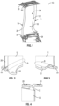
- FIG. 1 represents an OGV 10 which comprises a blade 12 having an intrados face 18 and an extrados face 28 extending between a leading edge 14 and a trailing edge 16, and the longitudinal ends of which are connected to platforms: inter-OGV platforms 20 attached to the outer radial end of the blading, and which are arranged between said OGV and the adjacent OGVs, and a platform 22 attached to an inner radial end of the blading, and connected to the hub 24 of the flow straightener.
- the metal reinforcement advantageously protects the OGV from erosion and potential impacts.
- a composite OGV is also known with a hybrid architecture with a carbon braid for the creation of the aerodynamic zone and a thermoplastic resin (with or without filler) to form the core of the OGV.
- this OGV has lower mechanical properties, weaker than conventional armor.
- thermoplastic resin only fills the cavity between the blade attachment platforms, and therefore does not limit the opening of the platforms, which would reduce the mechanical stresses experienced by the OGV.
- the invention aims to propose a solution making it possible to remedy at least some of these drawbacks.
- the invention allows a limitation of the opening of the platforms of a blade made of composite material for a turbomachine, for a reduction of the constraints in the connection fillets (critical zones) between the blade and the platforms.
- the step of adding the second metal reinforcement consists of gluing the second metal reinforcement to at least part of the intrados and extrados portions of the platform and in the decoupling.
- the step of adding the second metal reinforcement consists of a co-injection of the second metal reinforcement on at least part of the intrados and extrados portions of the platform and in the decoupling.
- the invention also relates to a blade made of composite material for a turbomachine, in particular an aircraft one, 1. according to claim 4.
- this blade comprises a second metal reinforcement arranged on at least part of the intrados and extrados portions of the platform and in the decoupling.
- the invention advantageously allows a reduction in stresses in the connection fillet, i.e. in the critical zone, between the blade and the platform, to ensure mechanical robustness.
- the second metal reinforcement serves as a connection between the intrados and extrados portions of the platform, and thus reinforces the critical area.
- this metal reinforcement significantly improves the correct formation of the OGV radii, particularly compared to a carbon braid which is not rigid and does not have the exact shape of the cavity.
- the second metal reinforcement advantageously limits the opening of the intrados and extrados portions of the platform, by reducing the stresses at the fillet under tensile, compressive and bending stress.
- the second metal reinforcement allows the forces of the fillet to be absorbed, and, in particular for compression, to distribute the forces over the entire base of the platforms, which increases the critical buckling force.
- a dimension of the second metal reinforcement in a longitudinal direction to the intrados and extrados faces of the blade between the leading and trailing edges is substantially equal to a dimension of the platform in said direction.
- the second metal reinforcement extends over the entire length of the platform.
- the second metal reinforcement comprises two parts, each part of the second metal reinforcement having a dimension in a longitudinal direction to the intrados and extrados faces of the blade between the leading and trailing edges of between 15% and 35% of a chord at the longitudinal end of the blade before the fillet.
- the second metal reinforcement extends only over a portion of the length of the platform.
- a dimension of the second metal reinforcement along the longitudinal direction of the blade may be between 30% and 70% of a dimension of the platform along said direction.
- the thickness of the second metal reinforcement is between 30% and 70% of the thickness of the platform.
- the dimension of the second metal reinforcement in the longitudinal direction of the blade is substantially equal to 50% of the dimension of the platform in this direction.
- a dimension of the second metal reinforcement in a direction orthogonal to the longitudinal direction of the blade and to the longitudinal direction of the intrados and extrados faces of the blade between the leading and trailing edges may be at least equal to a dimension of the platform in said direction.
- the width of the second metal reinforcement is at least equal to the width of the platform.
- the platform is a platform radially internal to the rectifier relative to an axis of said rectifier.
- the second metal reinforcement comprises, at a longitudinal end opposite the trailing edge of the blade, a protrusion extending orthogonally to this platform. This protrusion makes it possible to integrate a conical bearing function into the second metal reinforcement.
- the second metal reinforcement is made of titanium.
- the second metal reinforcement is made of a metal material compatible with the composite material of the flow straightener blade, i.e. with a material which does not have any incompatibilities with this composite material.
- THE figures 5 to 8 represent blades 100 made of composite material for an aircraft turbomachine, for example OGVs.
- the invention also applies to blades made of composite material for an unducted fan, particularly for an aircraft, known by the English acronyms “propfan” or “open rotor”.
- the blade 100 according to the invention is made from a fiber preform, for example made of carbon fibers, resulting from 3D weaving.
- the preform is woven in one piece.
- the preform is then molded with resin, for example epoxy resin.
- the blade 100 comprises an aerodynamically profiled blade 102, of elongated shape, having an intrados face 104 and an extrados face 106 extending between an edge leading edge 108 and a trailing edge 110 opposite the leading edge.
- the blade 102 is laterally delimited by the intrados face 104 and the extrados face 106 which connect the leading edge 108 and the trailing edge 110.
- the leading edge 108 is arranged upstream in the direction of flow of the gases in the turbomachine.
- the intrados 104 and extrados 106 faces are curved, and respectively concave and convex.
- the blade 102 extends longitudinally along the X axis, shown in the figures 5 to 8 .
- a first longitudinal end of the blade 102 is connected to a first platform 112, and a second longitudinal end of the blade 102 is connected to a second platform 114.
- the lower longitudinal end of the blade 102 is connected to a radially internal platform 112
- the upper longitudinal end of the blade 102 is connected to a radially external platform 114.
- the blade 102 is delimited radially between an internal platform 112 and an external platform 114.
- the platforms 112, 114 extend orthogonally to the longitudinal direction of the blade 102, i.e. to the X axis.
- the platforms 112, 114 extend in a longitudinal direction to the intrados 104 and extrados 106 faces of the blade 102 between the leading 108 and trailing 110 edges, represented by the Y axis, called the longitudinal direction of the platform, and in a direction orthogonal to the longitudinal direction of the blade 102 (X axis) and to the longitudinal direction of the platform (Y axis), represented by the Z axis, called the radial direction, or width, of the platform.
- Each platform 112, 114 comprises a lower surface portion 116 and an upper surface portion 118.
- the lower surface 116 and upper surface 118 portions are connected to the blade 102 by a connecting fillet 120.
- a gap 122 is formed in the fiber preform forming the blade, between the lower surface 116 and upper surface 118 portions of the platform 112, 114.
- the blade 100 also includes a metal reinforcement 124, in the form of a metal foil, attached to the leading edge 108 of the blade 102.
- the metal reinforcement 124 can be made of Nickel-Cobalt, or any other metal material compatible with the composite material of the blade 100. This reinforcement metallic 124 advantageously improves the mechanical strength of the blade 100.
- the blade 100 also comprises a metal reinforcement 126 arranged on at least part of the intrados 116 and extrados 118 portions of the platform 112 and in the decoupling 122.
- This metal reinforcement 126 makes it possible to reinforce the connection between the blade 102 and the platform 112, and therefore to reduce the stresses in the connection fillet 120, which makes it possible to improve the mechanical robustness of the blade 100.
- the blade 100 also comprises a metal reinforcement 128 arranged on at least part of the intrados 116 and extrados 118 portions of the platform 114 and in the decoupling 122.
- this metal reinforcement 128 makes it possible to reinforce the connection between the blade 102 and the platform 114, and therefore to reduce the stresses in the connection fillet 120, which makes it possible to improve the mechanical robustness of the blade 100.
- the metal reinforcements 126, 128 can be made of titanium, or any other metallic material compatible with the composite material of the blade 100.
- the metal reinforcements 126, 128 extend along the longitudinal direction of the platform (Y axis), and along the radial direction of the platform (Z axis).
- the metal reinforcement 128 may extend over the entire length Ip (Y axis) of the platform 112, 114. In this case, the dimension of the metal reinforcement 128 in the longitudinal direction of the platform (Y axis) is substantially equal to the length Ip of the platform 112, 114.
- the metal reinforcement 128 may extend over only part of the length (Y axis) of the platform 112, 114.
- the metal reinforcement may comprise a first part 130 and a second part 132.
- Each part 130, 132 of the metal reinforcement has a dimension in the longitudinal direction of the platform (Y axis) of between 15% and 35% of a chord C at the longitudinal end of the blade 102 before the fillet 120.
- the chord C corresponds to the dimension of the blade 102, along the intrados face or the extrados face, between the leading and trailing edges, at one end of blade 102, near the fillet 120.
- the length Ir1 of the part 130 of the metal reinforcement is between 15% and 35% of the chord C
- the length Ir2 of the part 132 of the metal reinforcement is between 15% and 35% of the chord C.
- the sum of the lengths Ir1 and Ir2 of the parts 130, 132 of the metal reinforcement is less than the length Ip of the platform 112.
- the length of the chord C is greater than the length Ip of the platform 112.
- the dimension of the metal reinforcement 128 in the longitudinal direction of the blade 102 can be between 30% and 70%, depending on the stress, preferably around 50%, of the thickness ep of the platform 114.
- the radial dimension Lr (Z axis), i.e. the width, of the metal reinforcement 128 may be at least equal to the radial dimension of the platform 114.
- the metal reinforcement 128 covers the entire base of the platforms 112, 114 and reaches the uncoupling 122.
- the metal reinforcement thus covers at least the outline of the entire platform 112, 114.
- the metal reinforcement 128 comprises, at a longitudinal end opposite the trailing edge 110 of the blade 102, a protrusion 134, which extends orthogonally to the platform 112.
- the protrusion 134 has a conical bearing function.
- this metal reinforcement 128 can cause the blade 100 to pass into a conical bearing.
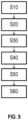
- the manufacturing process of the previously described blade is shown in figure 9
- the manufacturing method comprises a step S10 of weaving fibers in 3D so as to produce the fiber preform, then a step S20 of mounting the fiber preform in a mold, then a step S30 of injecting resin into the mold, in order to impregnate the fiber preform, and finally a step S40 of polymerizing the resin so as to form the blade.
- the manufacturing method comprises a step S50 of reinforcing the leading edge 108 of the blade 102, by integrating the metal reinforcement 124 on the leading edge 108.
- the reinforcement metal reinforcement 124 may be co-injected onto the leading edge 108 of the blade 102.
- the metal reinforcement 124 may be bonded to the leading edge 108 of the blade 102.
- the manufacturing method comprises a step S60 of reinforcing the connection fillets 120, by integrating second metal reinforcements 126, 128, 130, 132 on at least a portion of the intrados 108 and extrados 110 portions of the platforms 112, 114 and in the decouplings 122.
- the metal reinforcement 126, 128 can be co-injected onto at least a portion of the intrados 108 and extrados 110 portions of the platforms 112, 114 and in the decouplings 122.
- the metal reinforcement 126, 128 can be bonded onto at least a portion of the intrados 108 and extrados 110 portions of the platforms 112, 114 and in the disconnections 122.
Landscapes
- Engineering & Computer Science (AREA)
- Mechanical Engineering (AREA)
- Chemical & Material Sciences (AREA)
- Composite Materials (AREA)
- Manufacturing & Machinery (AREA)
- General Engineering & Computer Science (AREA)
- Materials Engineering (AREA)
- Textile Engineering (AREA)
- Structures Of Non-Positive Displacement Pumps (AREA)
- Moulding By Coating Moulds (AREA)
- Turbine Rotor Nozzle Sealing (AREA)
Description
- L'invention se rapporte au domaine des aubes en matériau composite pour une turbomachine, notamment d'aéronef, et plus précisément à l'amélioration de la tenue mécanique d'une telle aube en matériau composite.
- L'état de la technique comporte notamment les documents
WO 2013/060977 A2 ,FR 3 079 445 A1 WO 2018/158544 A1 etUS 2013/052030 A1 . - De façon connue, des aubes directrices de flux de sortie (OGV, acronyme de l'expression anglaise « Outlet Guide Vane ») sont utilisées en aéronautique. Un OGV est un aubage fixe dont la fonction consiste à redresser le flux à la sortie d'une aube de soufflante dans le flux secondaire d'une turbomachine.
- Les OGV forment des rangées d'aubes fixes qui permettent de guider le flux traversant la turbomachine, selon une vitesse et un angle appropriés.
- Par convention, dans la présente demande, les termes « amont » et « aval » sont définis par rapport au sens de circulation de l'air dans la turbomachine. De même, par convention dans la présente demande, les termes « intérieur » et « extérieur » ou « interne » et « externe » sont définis radialement par rapport à l'axe de la turbomachine.
- Les OGV peuvent être métalliques, ou bien en matériau composite, notamment pour en diminuer la masse.
- Actuellement, les OGV composites sont réalisées par injection de résine époxy, par exemple par moulage par injection de résine liquide (RTM, acronyme de l'expression anglaise « Resin Transfert Molding »), dans une préforme en fibres de carbone tissée en trois dimensions (3D).
- La
figure 1 représente un OGV 10 qui comporte une pale 12 ayant une face intrados 18 et une face extrados 28 s'étendant entre un bord d'attaque 14 et un bord de fuite 16, et dont les extrémités longitudinales sont reliées à des plateformes : des plateformes inter-OGV 20 rapportées sur l'extrémité radiale extérieure de l'aubage, et qui sont agencées entre ladite OGV et les OGV adjacentes, et une plateforme 22 rapportée sur une extrémité radiale intérieure de l'aubage, et reliée au moyeu 24 du redresseur de flux. - Un renfort métallique 26, sous la forme d'un clinquant métallique, par exemple en Nickel-Cobalt, est co-injecté sur la partie du bord d'attaque 14 de la pale 12. Les matériaux composites présentant une sensibilité à certaines contraintes mécaniques, le renfort métallique permet avantageusement de protéger de l'érosion et des potentiels impacts l'OGV.
- Il est également connu un OGV composite présentant une architecture hybride avec une tresse en matériau carbone pour la réalisation de la zone aérodynamique et une résine thermoplastique (avec ou sans charge) pour former l'âme de l'OGV.
- Toutefois, cet OGV présente des propriétés mécaniques moindres, plus faibles qu'une armure classique.
- De plus, la résine thermoplastique ne fait que combler la cavité entre les plateformes de fixation de l'aube, et ne permet donc pas de limiter l'ouverture des plateformes, ce qui diminuerait les contraintes mécaniques subies par l'OGV.
- Des études ont été réalisées pour analyser la tenue mécanique de cet OGV. D'après les résultats d'un modèle à éléments finis, une concentration systématique de contraintes se trouve au niveau des congés, représentés en pointillés A, B et C respectivement sur les
figures 2, 3 et 4 , c'est-à-dire au niveau de la jonction, entre les plateformes 20, 22 et la pale 12. - Des expertises des pièces suite à des essais de traction, de compression et de flexion ont également été réalisées. Les calculs montrent des zones de rupture identiques à celles relevées par l'expertise des essais.
- Il existe donc un besoin d'un OGV, dans lequel les contraintes dans ces zones de rupture sont diminuées, et dans lequel les efforts sont mieux répartis. L'invention a pour objectif de proposer une solution permettant de remédier à au moins certains de ces inconvénients.
- L'invention permet une limitation de l'ouverture des plateformes d'une aube en matériau composite pour une turbomachine, pour une diminution des contraintes dans les congés de raccordement (zones critiques) entre la pale et les plateformes.
- À cet effet, l'invention concerne un procédé de fabrication d'un redresseur de flux en matériau composite pour une turbomachine, notamment d'aéronef, comprenant les étapes :
- de tissage de fibres en trois dimensions de sorte à réaliser une préforme fibreuse,
- de montage de la préforme fibreuse dans un moule,
- d'injection, dans le moule, d'une résine, afin d'imprégner la préforme fibreuse,
- de polymérisation de la résine de manière à former l'aube, ladite aube comprenant une pale ayant une face intrados et une face extrados s'étendant entre un bord d'attaque et un bord de fuite, une extrémité longitudinale de ladite pale étant reliée à une plateforme, la plateforme comportant des portions intrados et extrados reliées à ladite pale par un congé de raccordement, et une déliaison étant formée dans ladite préforme fibreuse entre lesdites portions intrados et extrados de la plateforme,
- de renfort du bord d'attaque de ladite pale, par intégration d'un premier renfort métallique sur le bord d'attaque de la pale,
- de renfort des congés de raccordement, par l'intégration d'un deuxième renfort métallique sur au moins une partie des portions intrados et extrados de la plateforme et dans la déliaison.
- Selon un mode de réalisation, l'étape d'ajout du deuxième renfort métallique consiste en un collage du deuxième renfort métallique sur au moins une partie des portions intrados et extrados de la plateforme et dans la déliaison.
- Selon un autre mode de réalisation, l'étape d'ajout du deuxième renfort métallique consiste en une co-injection du deuxième renfort métallique sur au moins une partie des portions intrados et extrados de la plateforme et dans la déliaison.
- L'invention concerne également une aube en matériau composite pour une turbomachine, notamment d'aéronef, 1. selon la revendication 4. Ainsi, cette aube comprend un deuxième renfort métallique agencé sur au moins une partie des portions intrados et extrados de la plateforme et dans la déliaison.
- L'invention permet avantageusement une diminution des contraintes dans le congé de raccordement, c'est-à-dire dans la zone critique, entre la pale et la plateforme, pour assurer une robustesse mécanique.
- Avantageusement, le deuxième renfort métallique permet de servir de liaison entre les portions intrados et extrados de la plateforme, et permet ainsi de renforcer la zone critique. Dans le cadre d'une co-injection, ce renfort métallique améliore nettement la formation correcte les rayons de l'OGV notamment par rapport à une tresse en carbone qui n'est pas rigide et n'a pas la forme exacte de la cavité.
- Le deuxième renfort métallique permet avantageusement de limiter l'ouverture des portions intrados et extrados de la plateforme, en diminuant les contraintes au niveau du congé de raccordement sous sollicitation de traction, de compression et de flexion. De plus, le deuxième renfort métallique permet de reprendre les efforts du congé de raccordement, et, notamment pour la compression, de répartir, sur toute la base des plateformes, les efforts, ce qui augmente l'effort critique en flambage.
- Selon un mode de réalisation, une dimension du deuxième renfort métallique dans une direction longitudinale aux faces intrados et extrados de la pale entre les bords d'attaque et de fuite est sensiblement égale à une dimension de la plateforme dans ladite direction. Autrement dit, le deuxième renfort métallique s'étend sur toute la longueur de la plateforme.
- Selon un autre mode de réalisation, le deuxième renfort métallique comporte deux parties, chaque partie du deuxième renfort métallique ayant une dimension dans une direction longitudinale aux faces intrados et extrados de la pale entre les bords d'attaque et de fuite comprise entre 15 % et 35 % d'une corde à l'extrémité longitudinale de la pale avant le congé de raccordement. Autrement dit, le deuxième renfort métallique s'étend uniquement sur une partie de la longueur de la plateforme.
- Ceci permet avantageusement de diminuer la masse de l'aube de redresseur de flux, notamment en allégeant le deuxième renfort métallique.
- Une dimension du deuxième renfort métallique selon la direction longitudinale de la pale peut être comprise entre 30 % et 70 % d'une dimension de la plateforme selon ladite direction. Autrement dit, l'épaisseur du deuxième renfort métallique est comprise entre 30 % et 70 % de l'épaisseur de la plateforme.
- De préférence, la dimension du deuxième renfort métallique selon la direction longitudinale de la pale est sensiblement égale à 50 % de la dimension de la plateforme selon cette direction.
- Une dimension du deuxième renfort métallique dans une direction orthogonale à la direction longitudinale de la pale et à la direction longitudinale aux faces intrados et extrados de la pale entre les bords d'attaque et de fuite peut être au moins égale à une dimension de la plateforme dans ladite direction. Autrement dit, la largeur du deuxième renfort métallique est au moins égale à la largeur de la plateforme.
- Selon un mode de réalisation, la plateforme est une plateforme radialement interne au redresseur par rapport à un axe dudit redresseur. Dans ce mode de réalisation, le deuxième renfort métallique comporte, à une extrémité longitudinale en regard du bord de fuite de la pale, une excroissance s'étendant orthogonalement à cette plateforme. Cette excroissance permet d'intégrer au deuxième renfort métallique une fonction de portée conique.
- Selon un mode de réalisation, le deuxième renfort métallique est réalisé en titane. De préférence, le deuxième renfort métallique est réalisé en un matériau métallique compatible avec le matériau composite de l'aube de redresseur de flux, c'est-à-dire avec un matériau qui ne présente pas d'incompatibilités avec ce matériau composite.
- La présente invention sera mieux comprise et d'autres détails, caractéristiques et avantages de la présente invention apparaîtront plus clairement à la lecture de la description d'un exemple non limitatif qui suit, en référence aux dessins annexés sur lesquels :
- [
Fig. 1 ] lafigure 1 , déjà décrite, représente un OGV selon l'art antérieur, - [
Fig. 2 ] lafigure 2 , déjà décrite, représente une partie inférieure extrados/intrados amont d'un OGV selon l'art antérieur, - [
Fig. 3 ] lafigure 3 , déjà décrite, représente une partie inférieure extrados/intrados aval d'un OGV selon l'art antérieur, - [
Fig. 4 ] lafigure 4 , déjà décrite, représente une partie supérieure extrados/intrados aval d'un OGV selon l'art antérieur, - [
Fig. 5 ] lafigure 5 représente une partie inférieure d'une aube selon un mode de réalisation de l'invention, - [
Fig. 6 ] lafigure 6 représente une partie supérieure d'une aube selon un mode de réalisation de l'invention, - [
Fig. 7 ] lafigure 7 représente une partie inférieure d'une aube selon un autre mode de réalisation de l'invention, - [
Fig. 8 ] lafigure 8 représente une partie inférieure d'une aube selon encore un autre mode de réalisation de l'invention, et - [
Fig. 9 ] lafigure 9 est un organigramme d'un procédé de fabrication d'une aube selon l'invention. - Les éléments ayant les mêmes fonctions dans les différentes mises en œuvre ont les mêmes références dans les figures.
- Les
figures 5 à 8 représentent des aubes 100 en matériau composite pour une turbomachine d'aéronef, par exemple des OGV. L'invention s'applique également à des aubes en matériau composite pour une soufflante non carénée notamment d'aéronef, connue sous les acronymes anglais « propfan » ou « open rotor ». - L'aube 100 selon l'invention, et plus précisément la pale 102 est réalisée à partir d'une préforme fibreuse, par exemple en fibres de carbone, résultant d'un tissage en 3D. La préforme est tissée d'une seule pièce. La préforme est ensuite moulée avec de la résine, par exemple de la résine époxy.
- L'aube 100 comporte une pale 102 à profil aérodynamique, de forme allongée, ayant une face intrados 104 et une face extrados 106 s'étendant entre un bord d'attaque 108 et un bord de fuite 110 opposé au bord d'attaque. Autrement dit, la pale 102 est latéralement délimitée par la face intrados 104 et la face extrados 106 qui relient le bord d'attaque 108 et le bord de fuite 110. Le bord d'attaque 108 est disposé en amont suivant le sens d'écoulement des gaz dans la turbomachine. Les faces intrados 104 et extrados 106 sont incurvées, et respectivement concave et convexe. La pale 102 s'étend longitudinalement selon l'axe X, représenté sur les
figures 5 à 8 . - Une première extrémité longitudinale de la pale 102 est reliée à une première plateforme 112, et une seconde extrémité longitudinale de la pale 102 est reliée à une seconde plateforme 114. Par exemple, sur les
figures 5, 7 et 8 , l'extrémité longitudinale inférieure de la pale 102 est reliée à une plateforme 112 radialement interne, et sur lafigure 6 , l'extrémité longitudinale supérieure de la pale 102 est reliée à une plateforme 114 radialement externe. Autrement dit, la pale 102 est délimitée radialement entre une plateforme 112 interne et une plateforme 114 externe. Les plateformes 112, 114 s'étendent orthogonalement à la direction longitudinale de la pale 102, c'est-à-dire à l'axe X. Comme représenté sur lesfigures 5 à 8 , les plateformes 112, 114 s'étendent selon une direction longitudinale aux faces intrados 104 et extrados 106 de la pale 102 entre les bords d'attaque 108 et de fuite 110, représentée par l'axe Y, dite direction longitudinale de la plateforme, et selon une direction orthogonale à la direction longitudinale de la pale 102 (axe X) et à la direction longitudinale de la plateforme (axe Y), représentée par l'axe Z, dite direction radiale, ou largeur, de la plateforme. - Chaque plateforme 112, 114 comporte une portion intrados 116 et une portion extrados 118. Les portions intrados 116 et extrados 118 sont reliées à la pale 102 par un congé de raccordement 120. En particulier, une déliaison 122 est formée dans la préforme fibreuse formant l'aube, entre les portions intrados 116 et extrados 118 de la plateforme 112, 114.
- L'aube 100 comporte également un renfort métallique 124, sous la forme d'un clinquant métallique, rapporté sur le bord d'attaque 108 de la pale 102. Le renfort métallique 124 peut être réalisé en Nickel-Cobalt, ou en tout autre matériau métallique compatible avec le matériau composite de l'aube 100. Ce renfort métallique 124 permet avantageusement d'améliorer la tenue mécanique de l'aube 100.
- Comme représenté sur la
figure 5 , l'aube 100 comporte également un renfort métallique 126 agencé sur au moins une partie des portions intrados 116 et extrados 118 de la plateforme 112 et dans la déliaison 122. Ce renfort métallique 126 permet de renforcer la liaison entre la pale 102 et la plateforme 112, et donc de diminuer les contraintes dans le congé de raccordement 120, ce qui permet d'améliorer la robustesse mécanique de l'aube 100. - Comme représenté sur la
figure 6 , l'aube 100 comporte également un renfort métallique 128 agencé sur au moins une partie des portions intrados 116 et extrados 118 de la plateforme 114 et dans la déliaison 122. De même que le renfort métallique 126, ce renfort métallique 128 permet de renforcer la liaison entre la pale 102 et la plateforme 114, et donc de diminuer les contraintes dans le congé de raccordement 120, ce qui permet d'améliorer la robustesse mécanique de l'aube 100. - Les renforts métalliques 126, 128 peuvent être réalisés en titane, ou en tout autre matériau métallique compatible avec le matériau composite de l'aube 100.
- Les renforts métalliques 126, 128 s'étendent selon la direction longitudinale de la plateforme (axe Y), et selon la direction radiale de la plateforme (axe Z).
- Le renfort métallique 128 peut s'étendre sur toute la longueur Ip (axe Y) de la plateforme 112, 114. Dans ce cas, la dimension du renfort métallique 128 dans la direction longitudinale de la plateforme (axe Y) est sensiblement égale à la longueur Ip de la plateforme 112, 114.
- En variante représentée en
figure 7 , afin de diminuer la masse de l'aube 100, le renfort métallique 128 peut s'étendre sur une partie seulement de la longueur (axe Y) de la plateforme 112, 114. Dans ce cas, le renfort métallique peut comporter une première partie 130 et une deuxième partie 132. Chaque partie 130, 132 du renfort métallique a une dimension dans la direction longitudinale de la plateforme (axe Y) comprise entre 15 % et 35 % d'une corde C à l'extrémité longitudinale de la pale 102 avant le congé de raccordement 120. La corde C correspond à la dimension de la pale 102, le long de la face intrados ou de la face extrados, entre les bords d'attaque et de fuite, au niveau d'une extrémité de la pale 102, à proximité du congé de raccordement 120. Comme représenté sur lafigure 7 , la longueur Ir1 de la partie 130 du renfort métallique est comprise entre 15 % et 35 % de la corde C, et la longueur Ir2 de la partie 132 du renfort métallique est comprise entre 15 % et 35 % de la corde C. La somme des longueurs Ir1 et Ir2 des parties 130, 132 du renfort métallique est inférieure à la longueur Ip de la plateforme 112. Ici, la longueur de la corde C est supérieure à la longueur Ip de la plateforme 112. - Comme représenté sur la
figure 6 , la dimension du renfort métallique 128 dans la direction longitudinale de la pale 102 (axe X), c'est-à-dire l'épaisseur er du renfort métallique 128, peut être comprise entre 30 % et 70 %, en fonction de la sollicitation, de préférence aux alentours de 50 %, de l'épaisseur ep de la plateforme 114. - La dimension radiale Lr (axe Z), c'est-à-dire la largeur, du renfort métallique 128 peut être au moins égale à la dimension radiale de la plateforme 114. Ainsi, le renfort métallique 128 couvre la totalité de la base des plateformes 112, 114 et arrive jusqu'à la déliaison 122. Le renfort métallique couvre ainsi au minimum le contour de toute la plateforme 112, 114.
- Comme représenté en
figure 8 , le renfort métallique 128 comporte, à une extrémité longitudinale en regard du bord de fuite 110 de la pale 102, une excroissance 134, qui s'étend orthogonalement à la plateforme 112. L'excroissance 134 a une fonction de portée conique. Ainsi, ce renfort métallique 128 peut faire passer l'aube 100 en portée conique. - Le procédé de fabrication de l'aube précédemment décrite est représenté en
figure 9 . Le procédé de fabrication comprend une étape S10 de tissage de fibres en 3D de sorte à réaliser la préforme fibreuse, puis une étape S20 de montage de la préforme fibreuse dans un moule, puis une étape S30 d'injection, dans le moule, de la résine, afin d'imprégner la préforme fibreuse, et enfin une étape S40 de polymérisation de la résine de manière à former l'aube. - Afin d'augmenter la robustesse mécanique de l'aube 100, le procédé de fabrication comprend une étape S50 de renfort du bord d'attaque 108 de la pale 102, par intégration du renfort métallique 124 sur le bord d'attaque 108. Le renfort métallique 124 peut être co-injecté sur le bord d'attaque 108 de la pale 102. En variante, le renfort métallique 124 peut être collé sur le bord d'attaque 108 de la pale 102.
- Afin de réduire les contraintes au niveau des congés de raccordement 120 entre la pale 102 et les plateformes 112, 114 de l'aube 100 en matériau composite, le procédé de fabrication comprend une étape S60 de renfort des congés de raccordement 120, par intégration de deuxièmes renforts métalliques 126, 128, 130, 132 sur au moins une partie des portions intrados 108 et extrados 110 des plateformes 112, 114 et dans les déliaisons 122. Le renfort métallique 126, 128 peut être co-injecté sur au moins une partie des portions intrados 108 et extrados 110 des plateformes 112, 114 et dans les déliaisons 122. En variante, le renfort métallique 126, 128 peut être collé sur au moins une partie des portions intrados 108 et extrados 110 des plateformes 112, 114 et dans les déliaisons 122.
Claims (10)
- Procédé de fabrication d'une aube (100) en matériau composite pour une turbomachine, notamment d'aéronef, comprenant les étapes :- de tissage (S10) de fibres en trois dimensions de sorte à réaliser une préforme fibreuse,- de montage (S20) de la préforme fibreuse dans un moule,- d'injection (S30), dans le moule, d'une résine, afin d'imprégner la préforme fibreuse,- de polymérisation (S40) de la résine de manière à former l'aube (100), ladite aube comprenant une pale (102) ayant une face intrados (104) et une face extrados (106) s'étendant entre un bord d'attaque (108) et un bord de fuite (110), une extrémité longitudinale de ladite pale étant reliée à une plateforme (112, 114), la plateforme comportant des portions intrados (116) et extrados (118) reliées à ladite pale par un congé de raccordement (120), et une déliaison (122) étant formée dans ladite préforme fibreuse entre lesdites portions intrados et extrados de la plateforme,- de renfort (S50) du bord d'attaque de ladite pale, par intégration d'un premier renfort métallique (124) sur le bord d'attaque de la pale,caractérisé en ce que le procédé comprend également l'étape:- de renfort (S60) des congés de raccordement, par intégration d'un deuxième renfort métallique (126, 128, 130, 132) sur au moins une partie des portions intrados et extrados de la plateforme et dans la déliaison.
- Procédé de fabrication selon la revendication 1, dans lequel l'étape d'ajout du deuxième renfort métallique (126, 128, 130, 132) consiste en un collage du deuxième renfort métallique sur au moins une partie des portions intrados (116) et extrados (118) de la plateforme et dans la déliaison (122).
- Procédé de fabrication selon la revendication 1, dans lequel l'étape d'ajout du deuxième renfort métallique (126, 128, 130, 132) consiste en une co-injection du deuxième renfort métallique sur au moins une partie des portions intrados (116) et extrados (118) de la plateforme et dans la déliaison (122).
- Aube (100) en matériau composite pour une turbomachine, notamment d'aéronef, comprenant une pale (102) ayant une face intrados (104) et une face extrados (106) s'étendant entre un bord d'attaque (108) et un bord de fuite (110), la pale étant réalisée à partir d'une préforme fibreuse tissée en trois dimensions, une extrémité longitudinale de ladite pale étant reliée à une plateforme (112, 114), la plateforme comportant des portions intrados (116) et extrados (118) reliées à ladite pale par un congé de raccordement (120), une déliaison (122) étant formée dans ladite préforme fibreuse entre lesdites portions intrados et extrados de la plateforme, l'aube comportant un premier renfort métallique (124) sur le bord d'attaque (108) de la pale (102),
l'aube étant caractérisée en ce qu'elle comprend un deuxième renfort métallique (126, 128, 130, 132) agencé sur au moins une partie des portions intrados (116) et extrados (118) de la plateforme (112) et dans la déliaison (122). - Aube (100) en matériau composite selon la revendication 4, dans laquelle une dimension du deuxième renfort métallique (126, 128) dans une direction longitudinale (Y) aux faces intrados (104) et extrados (106) de la pale (102) entre les bords d'attaque (108) et de fuite (110) est sensiblement égale à une dimension (Ip) de la plateforme (112, 114) dans ladite direction.
- Aube (100) en matériau composite selon la revendication 4, dans laquelle le deuxième renfort métallique comporte deux parties (130, 132), chaque partie du deuxième renfort métallique ayant une dimension (Ir1, Ir2) dans une direction longitudinale (Y) aux faces intrados (104) et extrados (106) de la pale (102) entre les bords d'attaque (108) et de fuite (110) comprise entre 15 % et 35 % d'une corde (C) à l'extrémité longitudinale de la pale avant le congé de raccordement (120).
- Aube (100) en matériau composite selon l'une des revendications 4 à 6, dans laquelle une dimension (er) du deuxième renfort métallique (126, 128, 130, 132) selon la direction longitudinale (X) de la pale (102) est comprise entre 30 % et 70 % d'une dimension (ep) de la plateforme (112, 114) selon ladite direction.
- Aube (100) en matériau composite selon l'une des revendications 4 à 7, dans laquelle une dimension (Lr) du deuxième renfort métallique (126, 128, 130, 132) dans une direction orthogonale à la direction longitudinale (X) de la pale (102) et à la direction longitudinale (Y) aux faces intrados (104) et extrados (106) de la pale entre les bords d'attaque (108) et de fuite (110) est au moins égale à une dimension de la plateforme (112, 114) dans ladite direction.
- Aube (100) en matériau composite selon l'une des revendications 4 à 8, dans laquelle la plateforme (112) est une plateforme radialement interne au redresseur par rapport à un axe dudit redresseur, et dans laquelle le deuxième renfort métallique (128) comporte, à une extrémité longitudinale en regard du bord de fuite (110) de la pale (102), une excroissance (134) s'étendant orthogonalement à ladite plateforme.
- Aube (100) en matériau composite selon l'une des revendications 4 à 9, dans laquelle le deuxième renfort métallique (126, 128, 130, 132) est réalisé en titane.
Applications Claiming Priority (2)
| Application Number | Priority Date | Filing Date | Title |
|---|---|---|---|
| FR2003729A FR3109184B1 (fr) | 2020-04-14 | 2020-04-14 | Aube en matériau composite comportant des renforts métalliques, et procédé de fabrication d’une telle aube |
| PCT/FR2021/050642 WO2021209709A1 (fr) | 2020-04-14 | 2021-04-12 | Aube en matériau composite comportant des renforts métalliques, et procédé de fabrication d'une telle aube |
Publications (2)
| Publication Number | Publication Date |
|---|---|
| EP4136325A1 EP4136325A1 (fr) | 2023-02-22 |
| EP4136325B1 true EP4136325B1 (fr) | 2025-06-04 |
Family
ID=70804847
Family Applications (1)
| Application Number | Title | Priority Date | Filing Date |
|---|---|---|---|
| EP21726151.0A Active EP4136325B1 (fr) | 2020-04-14 | 2021-04-12 | Aube en matériau composite comportant des renforts métalliques, et procédé de fabrication d'une telle aube |
Country Status (5)
| Country | Link |
|---|---|
| US (1) | US11795836B2 (fr) |
| EP (1) | EP4136325B1 (fr) |
| CN (1) | CN115413305B (fr) |
| FR (1) | FR3109184B1 (fr) |
| WO (1) | WO2021209709A1 (fr) |
Families Citing this family (1)
| Publication number | Priority date | Publication date | Assignee | Title |
|---|---|---|---|---|
| US12188376B2 (en) | 2023-03-29 | 2025-01-07 | Pratt & Whitney Canada Corp. | Composite guide vane with insert |
Family Cites Families (12)
| Publication number | Priority date | Publication date | Assignee | Title |
|---|---|---|---|---|
| FR2965202B1 (fr) * | 2010-09-28 | 2012-10-12 | Snecma | Procede de fabrication d'une piece et piece massive composite obtenue par ce procede |
| US9103214B2 (en) * | 2011-08-23 | 2015-08-11 | United Technologies Corporation | Ceramic matrix composite vane structure with overwrap for a gas turbine engine |
| FR2981602B1 (fr) * | 2011-10-25 | 2017-02-17 | Snecma Propulsion Solide | Procede de fabrication d'un secteur de distributeur de turbine ou redresseur de compresseur en materiau composite pour turbomachine et turbine ou compresseur incorporant un distributeur ou un redresseur forme de tels secteurs |
| FR3037097B1 (fr) * | 2015-06-03 | 2017-06-23 | Snecma | Aube composite comprenant une plateforme munie d'un raidisseur |
| US20170081752A1 (en) * | 2015-09-21 | 2017-03-23 | Gary L. Hanley | Method for Producing a Near Net Shape Metallic Leading Edge |
| FR3059268B1 (fr) * | 2016-11-25 | 2020-02-21 | Safran Aircraft Engines | Procede de fabrication d'un element profile en materiau composite avec fixation d'un renfort metallique par rivetage. |
| FR3063514B1 (fr) * | 2017-03-02 | 2019-04-12 | Safran | Aube de turbomachine et procede pour sa fabrication |
| FR3079445B1 (fr) * | 2018-03-28 | 2020-04-24 | Safran | Procede de fabrication d'une aube en materiau composite a bord d'attaque metallique rapporte pour turbine a gaz |
| FR3102378B1 (fr) * | 2019-10-23 | 2021-11-12 | Safran Aircraft Engines | Procédé de fabrication d’une aube en matériau composite avec bord d’attaque métallique rapporté |
| FR3103730B1 (fr) * | 2019-11-29 | 2021-12-03 | Safran | Procede de fabrication d’une aube composite pour un moteur d’aeronef |
| FR3103731B1 (fr) * | 2019-11-29 | 2021-11-26 | Safran | Aube composite pour un moteur d’aeronef et ses procedes de fabrication et de reparation |
| FR3111658B1 (fr) * | 2020-06-18 | 2022-07-15 | Safran Aircraft Engines | Aube en matériau composite à renfort fibreux tissé tridimensionnel et peau tissée bidimensionnel et son procédé de fabrication |
-
2020
- 2020-04-14 FR FR2003729A patent/FR3109184B1/fr active Active
-
2021
- 2021-04-12 US US17/996,024 patent/US11795836B2/en active Active
- 2021-04-12 CN CN202180028556.XA patent/CN115413305B/zh active Active
- 2021-04-12 EP EP21726151.0A patent/EP4136325B1/fr active Active
- 2021-04-12 WO PCT/FR2021/050642 patent/WO2021209709A1/fr not_active Ceased
Also Published As
| Publication number | Publication date |
|---|---|
| CN115413305B (zh) | 2025-07-08 |
| US11795836B2 (en) | 2023-10-24 |
| WO2021209709A1 (fr) | 2021-10-21 |
| CN115413305A (zh) | 2022-11-29 |
| US20230184133A1 (en) | 2023-06-15 |
| EP4136325A1 (fr) | 2023-02-22 |
| FR3109184A1 (fr) | 2021-10-15 |
| FR3109184B1 (fr) | 2022-04-01 |
Similar Documents
| Publication | Publication Date | Title |
|---|---|---|
| EP3873725B1 (fr) | Aube de soufflante d'une turbomachine et une telle soufflante | |
| WO2022208002A1 (fr) | Aube comprenant une structure en matériau composite et procédé de fabrication associé | |
| EP3873724B1 (fr) | Hybridation des fibres du renfort fibreux d'une aube de soufflante | |
| EP4115053B1 (fr) | Aube de soufflante comprenant un insert de fibres raides | |
| BE1023290B1 (fr) | Aube composite de compresseur de turbomachine axiale | |
| EP4093670B1 (fr) | Aube comprenant une structure en matériau composite et procédé de fabrication associé | |
| EP3990752B1 (fr) | Plateforme inter-aube avec caisson sacrificiel | |
| EP4136325B1 (fr) | Aube en matériau composite comportant des renforts métalliques, et procédé de fabrication d'une telle aube | |
| EP3996990B1 (fr) | Aube de soufflante | |
| EP4022173B1 (fr) | Hybridation des fibres du renfort fibreux d'une aube de soufflante | |
| EP3894666B1 (fr) | Aube de soufflante comprenant un bouclier fin et un raidisseur | |
| EP4211336B1 (fr) | Hybridation des fibres du renfort fibreux d'une aube de soufflante avec des fibres élastiques | |
| FR3049002A1 (fr) | Pale de turbomachine aeronautique comprenant un element rapporte en materiau composite formant bord de fuite et procede de fabrication d'une telle pale | |
| EP3898157B1 (fr) | Preforme avec un renfort fibreux tisse en une seule piece pour plateforme inter aube | |
| FR3102086A1 (fr) | Aube en matériau composite comportant un renfort métallique, et procédés de fabrication et de réparation d’une telle aube | |
| EP4127409B1 (fr) | Aube de soufflante rotative de turbomachine, soufflante et turbomachine munies de celle-ci | |
| WO2025037061A1 (fr) | Aube de turbomachine monobloc | |
| FR3158537A1 (fr) | Aube composite de turbomachine comprenant un pied d’aube monolithique | |
| FR3138905A1 (fr) | Aubage fixe de turbomachine comprenant des aubes à calage variable | |
| EP4483041A1 (fr) | Systeme de fixation d'aube de turbomachine | |
| EP4473197A1 (fr) | Aube hybride metal/composite a orientation textile adaptee aux sollicitations mecaniques | |
| FR3136011A1 (fr) | Aube comprenant une structure en matériau composite et procédé de fabrication associé | |
| WO2025104409A1 (fr) | Bouchons solubles pour creation de cavite borgne dans un aubage composite | |
| FR3138904A1 (fr) | Aubage fixe de turbomachine comprenant des aubes à calage variable | |
| FR3108663A1 (fr) | Aube de soufflante rotative de turbomachine, soufflante et turbomachine munies de celle-ci |
Legal Events
| Date | Code | Title | Description |
|---|---|---|---|
| STAA | Information on the status of an ep patent application or granted ep patent |
Free format text: STATUS: UNKNOWN |
|
| STAA | Information on the status of an ep patent application or granted ep patent |
Free format text: STATUS: THE INTERNATIONAL PUBLICATION HAS BEEN MADE |
|
| PUAI | Public reference made under article 153(3) epc to a published international application that has entered the european phase |
Free format text: ORIGINAL CODE: 0009012 |
|
| STAA | Information on the status of an ep patent application or granted ep patent |
Free format text: STATUS: REQUEST FOR EXAMINATION WAS MADE |
|
| 17P | Request for examination filed |
Effective date: 20221114 |
|
| AK | Designated contracting states |
Kind code of ref document: A1 Designated state(s): AL AT BE BG CH CY CZ DE DK EE ES FI FR GB GR HR HU IE IS IT LI LT LU LV MC MK MT NL NO PL PT RO RS SE SI SK SM TR |
|
| DAV | Request for validation of the european patent (deleted) | ||
| DAX | Request for extension of the european patent (deleted) | ||
| STAA | Information on the status of an ep patent application or granted ep patent |
Free format text: STATUS: EXAMINATION IS IN PROGRESS |
|
| RIC1 | Information provided on ipc code assigned before grant |
Ipc: B29L 31/08 20060101ALI20240119BHEP Ipc: B29C 70/86 20060101ALI20240119BHEP Ipc: B29C 70/48 20060101ALI20240119BHEP Ipc: B29C 70/24 20060101ALI20240119BHEP Ipc: B29D 99/00 20100101ALI20240119BHEP Ipc: B29C 65/00 20060101ALI20240119BHEP Ipc: F01D 5/28 20060101AFI20240119BHEP |
|
| 17Q | First examination report despatched |
Effective date: 20240202 |
|
| GRAP | Despatch of communication of intention to grant a patent |
Free format text: ORIGINAL CODE: EPIDOSNIGR1 |
|
| STAA | Information on the status of an ep patent application or granted ep patent |
Free format text: STATUS: GRANT OF PATENT IS INTENDED |
|
| RIC1 | Information provided on ipc code assigned before grant |
Ipc: B29B 11/16 20060101ALN20241118BHEP Ipc: B29L 31/08 20060101ALI20241118BHEP Ipc: B29C 70/86 20060101ALI20241118BHEP Ipc: B29C 70/48 20060101ALI20241118BHEP Ipc: B29C 70/24 20060101ALI20241118BHEP Ipc: B29D 99/00 20100101ALI20241118BHEP Ipc: B29C 65/00 20060101ALI20241118BHEP Ipc: F01D 5/28 20060101AFI20241118BHEP |
|
| INTG | Intention to grant announced |
Effective date: 20241206 |
|
| GRAS | Grant fee paid |
Free format text: ORIGINAL CODE: EPIDOSNIGR3 |
|
| GRAA | (expected) grant |
Free format text: ORIGINAL CODE: 0009210 |
|
| STAA | Information on the status of an ep patent application or granted ep patent |
Free format text: STATUS: THE PATENT HAS BEEN GRANTED |
|
| AK | Designated contracting states |
Kind code of ref document: B1 Designated state(s): AL AT BE BG CH CY CZ DE DK EE ES FI FR GB GR HR HU IE IS IT LI LT LU LV MC MK MT NL NO PL PT RO RS SE SI SK SM TR |
|
| REG | Reference to a national code |
Ref country code: GB Ref legal event code: FG4D Free format text: NOT ENGLISH |
|
| REG | Reference to a national code |
Ref country code: CH Ref legal event code: EP |
|
| REG | Reference to a national code |
Ref country code: DE Ref legal event code: R096 Ref document number: 602021031780 Country of ref document: DE |
|
| REG | Reference to a national code |
Ref country code: IE Ref legal event code: FG4D Free format text: LANGUAGE OF EP DOCUMENT: FRENCH |
|
| REG | Reference to a national code |
Ref country code: NL Ref legal event code: MP Effective date: 20250604 |
|
| PG25 | Lapsed in a contracting state [announced via postgrant information from national office to epo] |
Ref country code: FI Free format text: LAPSE BECAUSE OF FAILURE TO SUBMIT A TRANSLATION OF THE DESCRIPTION OR TO PAY THE FEE WITHIN THE PRESCRIBED TIME-LIMIT Effective date: 20250604 Ref country code: ES Free format text: LAPSE BECAUSE OF FAILURE TO SUBMIT A TRANSLATION OF THE DESCRIPTION OR TO PAY THE FEE WITHIN THE PRESCRIBED TIME-LIMIT Effective date: 20250604 |
|
| REG | Reference to a national code |
Ref country code: LT Ref legal event code: MG9D |
|
| PG25 | Lapsed in a contracting state [announced via postgrant information from national office to epo] |
Ref country code: NO Free format text: LAPSE BECAUSE OF FAILURE TO SUBMIT A TRANSLATION OF THE DESCRIPTION OR TO PAY THE FEE WITHIN THE PRESCRIBED TIME-LIMIT Effective date: 20250904 Ref country code: GR Free format text: LAPSE BECAUSE OF FAILURE TO SUBMIT A TRANSLATION OF THE DESCRIPTION OR TO PAY THE FEE WITHIN THE PRESCRIBED TIME-LIMIT Effective date: 20250905 |
|
| PG25 | Lapsed in a contracting state [announced via postgrant information from national office to epo] |
Ref country code: PL Free format text: LAPSE BECAUSE OF FAILURE TO SUBMIT A TRANSLATION OF THE DESCRIPTION OR TO PAY THE FEE WITHIN THE PRESCRIBED TIME-LIMIT Effective date: 20250604 |
|
| PG25 | Lapsed in a contracting state [announced via postgrant information from national office to epo] |
Ref country code: BG Free format text: LAPSE BECAUSE OF FAILURE TO SUBMIT A TRANSLATION OF THE DESCRIPTION OR TO PAY THE FEE WITHIN THE PRESCRIBED TIME-LIMIT Effective date: 20250604 |
|
| PG25 | Lapsed in a contracting state [announced via postgrant information from national office to epo] |
Ref country code: HR Free format text: LAPSE BECAUSE OF FAILURE TO SUBMIT A TRANSLATION OF THE DESCRIPTION OR TO PAY THE FEE WITHIN THE PRESCRIBED TIME-LIMIT Effective date: 20250604 |
|
| PG25 | Lapsed in a contracting state [announced via postgrant information from national office to epo] |
Ref country code: RS Free format text: LAPSE BECAUSE OF FAILURE TO SUBMIT A TRANSLATION OF THE DESCRIPTION OR TO PAY THE FEE WITHIN THE PRESCRIBED TIME-LIMIT Effective date: 20250904 |
|
| PG25 | Lapsed in a contracting state [announced via postgrant information from national office to epo] |
Ref country code: LV Free format text: LAPSE BECAUSE OF FAILURE TO SUBMIT A TRANSLATION OF THE DESCRIPTION OR TO PAY THE FEE WITHIN THE PRESCRIBED TIME-LIMIT Effective date: 20250604 |
|
| PG25 | Lapsed in a contracting state [announced via postgrant information from national office to epo] |
Ref country code: NL Free format text: LAPSE BECAUSE OF FAILURE TO SUBMIT A TRANSLATION OF THE DESCRIPTION OR TO PAY THE FEE WITHIN THE PRESCRIBED TIME-LIMIT Effective date: 20250604 |