EP4135866B1 - Interaktive objektsysteme und verfahren - Google Patents
Interaktive objektsysteme und verfahren Download PDFInfo
- Publication number
- EP4135866B1 EP4135866B1 EP21723570.4A EP21723570A EP4135866B1 EP 4135866 B1 EP4135866 B1 EP 4135866B1 EP 21723570 A EP21723570 A EP 21723570A EP 4135866 B1 EP4135866 B1 EP 4135866B1
- Authority
- EP
- European Patent Office
- Prior art keywords
- interactive object
- electromagnetic radiation
- power
- infrared light
- light source
- Prior art date
- Legal status (The legal status is an assumption and is not a legal conclusion. Google has not performed a legal analysis and makes no representation as to the accuracy of the status listed.)
- Active
Links
Images




Classifications
-
- A—HUMAN NECESSITIES
- A63—SPORTS; GAMES; AMUSEMENTS
- A63G—MERRY-GO-ROUNDS; SWINGS; ROCKING-HORSES; CHUTES; SWITCHBACKS; SIMILAR DEVICES FOR PUBLIC AMUSEMENT
- A63G31/00—Amusement arrangements
-
- G—PHYSICS
- G02—OPTICS
- G02B—OPTICAL ELEMENTS, SYSTEMS OR APPARATUS
- G02B27/00—Optical systems or apparatus not provided for by any of the groups G02B1/00 - G02B26/00, G02B30/00
- G02B27/10—Beam splitting or combining systems
- G02B27/14—Beam splitting or combining systems operating by reflection only
- G02B27/144—Beam splitting or combining systems operating by reflection only using partially transparent surfaces without spectral selectivity
-
- G—PHYSICS
- G02—OPTICS
- G02B—OPTICAL ELEMENTS, SYSTEMS OR APPARATUS
- G02B5/00—Optical elements other than lenses
- G02B5/12—Reflex reflectors
- G02B5/126—Reflex reflectors including curved refracting surface
-
- H—ELECTRICITY
- H02—GENERATION; CONVERSION OR DISTRIBUTION OF ELECTRIC POWER
- H02J—ELECTRIC POWER NETWORKS; CIRCUIT ARRANGEMENTS OR SYSTEMS FOR SUPPLYING OR DISTRIBUTING ELECTRIC POWER; SYSTEMS FOR STORING ELECTRIC ENERGY
- H02J50/00—Circuit arrangements or systems for wireless supply or distribution of electric power
- H02J50/001—Energy harvesting or scavenging
-
- H—ELECTRICITY
- H02—GENERATION; CONVERSION OR DISTRIBUTION OF ELECTRIC POWER
- H02J—ELECTRIC POWER NETWORKS; CIRCUIT ARRANGEMENTS OR SYSTEMS FOR SUPPLYING OR DISTRIBUTING ELECTRIC POWER; SYSTEMS FOR STORING ELECTRIC ENERGY
- H02J50/00—Circuit arrangements or systems for wireless supply or distribution of electric power
- H02J50/30—Circuit arrangements or systems for wireless supply or distribution of electric power using light, e.g. lasers
-
- H—ELECTRICITY
- H04—ELECTRIC COMMUNICATION TECHNIQUE
- H04N—PICTORIAL COMMUNICATION, e.g. TELEVISION
- H04N23/00—Cameras or camera modules comprising electronic image sensors; Control thereof
- H04N23/20—Cameras or camera modules comprising electronic image sensors; Control thereof for generating image signals from infrared radiation only
- H04N23/21—Cameras or camera modules comprising electronic image sensors; Control thereof for generating image signals from infrared radiation only from near infrared [NIR] radiation
-
- H—ELECTRICITY
- H04—ELECTRIC COMMUNICATION TECHNIQUE
- H04N—PICTORIAL COMMUNICATION, e.g. TELEVISION
- H04N5/00—Details of television systems
- H04N5/30—Transforming light or analogous information into electric information
- H04N5/33—Transforming infrared radiation
-
- A—HUMAN NECESSITIES
- A63—SPORTS; GAMES; AMUSEMENTS
- A63F—CARD, BOARD, OR ROULETTE GAMES; INDOOR GAMES USING SMALL MOVING PLAYING BODIES; VIDEO GAMES; GAMES NOT OTHERWISE PROVIDED FOR
- A63F2300/00—Features of games using an electronically generated display having two or more dimensions, e.g. on a television screen, showing representations related to the game
- A63F2300/60—Methods for processing data by generating or executing the game program
- A63F2300/66—Methods for processing data by generating or executing the game program for rendering three dimensional images
- A63F2300/6661—Methods for processing data by generating or executing the game program for rendering three dimensional images for changing the position of the virtual camera
- A63F2300/6684—Methods for processing data by generating or executing the game program for rendering three dimensional images for changing the position of the virtual camera by dynamically adapting its position to keep a game object in its viewing frustrum, e.g. for tracking a character or a ball
-
- G—PHYSICS
- G02—OPTICS
- G02B—OPTICAL ELEMENTS, SYSTEMS OR APPARATUS
- G02B5/00—Optical elements other than lenses
- G02B5/12—Reflex reflectors
Definitions
- US2019/220634 describes a system that includes a radio-frequency identification (RFID) reader configured to read data stored on an RFID tag associated with a user and to generate a first signal indicative of the data and indicative of a location of the RFID tag, a sensor system configured to detect a user interaction with an interactive element and to generate a second signal indicative of the user interaction, and a processor configured to match the user to the user interaction based on the first signal and the second signal and to update a user database to reflect that the user is matched to the user interaction.
- RFID radio-frequency identification
- Guests of an immersive or themed environment may enjoy carrying a handheld object or wearing a costume element that aligns with the theme, such as a sword, stuffed animal, hat, wand, jewelry, or other prop. While these objects may have certain interactivity, typically the interactions are mediated by external devices that recognize the object (e.g., image recognition) and activate external actions based on the recognition. Such an arrangement permits the objects to be implemented as relatively inexpensive passive devices, with the more complex and costly elements of the interactions being off-board or external to the passive device. A challenge of managing interactions using such unpowered passive devices is the lack of feedback or effects that take place on or in the passive devices. While guest feedback systems can be situated as fixed components of the environment, the ability to generate feedback in or on a passive device can facilitate a deeper level of immersion in to the themed environment.
- guest feedback systems can be situated as fixed components of the environment, the ability to generate feedback in or on a passive device can facilitate a deeper level of immersion in to the themed environment.
- Presently disclosed embodiments are directed to special effects of a handheld or other interactive object that carries no or relatively low-power internal power supplies and that is passively powered using harvested optical or other electromagnetic energy from an external source.
- the power harvesting may be used to power an on-board special effect system of the interactive object or to power other feedback systems of the device.
- the interactive object may, in certain implementations, exclude visible power buttons or activation features as well as heavy or costly power supplies.
- the one or more on-board special effect systems are passively activated as part of an interactive object system that directs electromagnetic radiation (which may be in a nonvisible wavelength range) to the interactive object to activate its special effects or other feedback systems.
- electromagnetic radiation which may be in a nonvisible wavelength range
- the disclosed embodiments facilitate activation of interactive object special effects independent of a user harvesting sufficient motion-based power, which permits users of a variety of abilities and interests to enjoy an immersive environment and to participate in a group narrative as directed by a control system.
- passive power harvesting may provide maintenance advantages, and users need not be concerned with replacing batteries before interacting with immersive environments.
- the interactive object system may incorporate a source of electromagnetic radiation that can be focused on a sufficiently small location such that only a desired interactive object or set of interactive objects is powered.
- the interactive object may include a marker, such as a retroreflective marker, that is detectable within the environment and that may be used to direct the electromagnetic energy to the location of interactive object.
- Such objects may, in an embodiment, be a prop or toy used within an interactive environment to permit greater variability in special effect control by using power harvesting.
- the use of power harvesting permits a user to move freely within an immersive environment while the interactive object receives power to activate an on-board special effect.
- Such objects may include wearable objects, such as clothing, jewelry, bracelets, headgear, glasses.
- the object may be a prop or scenery item within an immersive environment.
- the immersive environment may be an environment of an amusement park, an entertainment complex, a retail establishment, etc.
- the interactive object control system 10 may include an interactive object 20 (illustrated as a handheld object) that includes a housing 22 having an exterior surface 24 formed at least in part from a material that permits certain wavelengths of electromagnetic radiation, that are used to power on-board special effects, to pass through the exterior surface 24 to be received by interior power harvesting circuitry of a power harvesting device that is housed on or in the interactive object 20.
- the interactive object may also include a retroreflective marker 26 positioned on or in the exterior surface 24. While the illustrated embodiment shows a single interactive object 20, it should be understood that the system 10 may be used in conjunction with one or more interactive objects 20 in the immersive environment.
- the emitter 14 is external to (e.g., spaced apart from) the interactive object 20.
- the emitter 14 operates to emit electromagnetic radiation, which is represented by an expanding electromagnetic radiation beam 28 for illustrative purposes, to selectively illuminate, bathe, or flood an area 30 in the electromagnetic radiation.
- the electromagnetic radiation beam 28 in certain embodiments, may be representative of multiple light beams (beams of electromagnetic radiation) being emitted from different sources 31 of the emitter or emitters 14 (all part of an emission subsystem that includes one or more emitters 14).
- the source 31 may be a visible light source, an infrared light source, etc, to emit the desired wavelength of electromagnetic radiation.
- certain forms of electromagnetic radiation such as certain wavelengths of light (e.g., infrared) may be more desirable than others, depending on the particular setting (e.g., whether the setting is "dark," or whether people are expected to cross the path of the beam).
- certain wavelengths of light e.g., infrared
- the area 30 may correspond to all or a part of an amusement park attraction area or immersive environment, such as a stage show, a ride vehicle loading area, a waiting area outside of an entrance to a ride or show, and so forth.
- the emitter 14 is fixed in position within the environment while the interactive object 20 moves freely within the environment to move within the area 30 and receive the electromagnetic radiation 28. Accordingly, the interactive object 20 may be detected (e.g., located within the area 30), tracked, and powered to activate one or more special effects that originate from the interactive object 20 via emitted and detected electromagnetic radiation 28 of the interactive object control system 10.
- the electromagnetic radiation 28 (shown as electromagnetic radiation 28a) from the emitter 14 acts as a power source for the interactive object 20, which in turn uses the harvested power to activate one or more onboard special effects of a special effect system 36, which may include light, sound, fluid, haptic, or other special effects that, when activated, originated from the interactive object 20.
- the special effect system 36 is part of the interactive object 20 and may be contained in part within or on the housing 22 and may also include one or more features that are disposed on or visible from the exterior surface 24 to permit the user to view or experience the activated special effect. Such features may include light sources, speakers, haptic feedback devices, ports that release special effect materials (smoke, confetti, fluids), and/or actuatable elements that move in response to activation.
- the emitter 14 and detector 16 operate under direction of the control unit 18.
- the location of the interactive object 20 within the cone of the electromagnetic radiation 28 triggers activation of the emitter 14 to drive a light source that emits a beam of electromagnetic radiation that corresponds with the activating wavelength of a power harvesting device 38.
- the wavelength or wavelengths reflected by the retroreflective marker 26 also correspond to wavelengths used for power harvesting by the power harvesting device 38. In this manner, the detection wavelength, used to located and track the interactive object 20, is also used to passively power on-board special effects of the interactive object.
- the resulting power can be harnessed to perform a myriad of on-board operations of the interactive object 20, including but not limited to computation, sensing, data transceiving (e.g., under instructions from an object controller 39), and sounds, lights and motion via the special effect system 36.
- the detector 16 may be configured to detect wavelengths of electromagnetic radiation retro-reflected by the retroreflective markers 26 while filtering wavelengths of electromagnetic radiation not retro-reflected by the markers 26, including those wavelengths of interest.
- the detector 16 may be a camera having a plurality of electromagnetic radiation capturing features (e.g., charge-coupled devices (CCDs) and/or complementary metal oxide semiconductor (CMOS) sensors corresponding to pixels).
- CCDs charge-coupled devices
- CMOS complementary metal oxide semiconductor
- the detector 16 may be an amp ® high dynamic range (HDR) camera system available from Contrast Optical Design and Engineering, Inc. of Albuquerque, NM.
- HDR high dynamic range
- the control unit 18 that drives the emitter 14 and that receives and processes data from the detector 16 may include one or more processors 40 and one or more memory 42, which may generally referred to herein as "processing circuitry.”
- the one or more processors 40 may include one or more application specific integrated circuits (ASICs), one or more field programmable gate arrays (FPGAs), one or more general purpose processors, or any combination thereof.
- the one or more memory 42 may include volatile memory, such as random access memory (RAM), and/or non-volatile memory, such as read-only memory (ROM), optical drives, hard disc drives, or solid-state drives.
- the arrangement of the one or more emitters 14, one or more detectors 16, the control unit 18, and other features may vary based on application-specific considerations and the manner in which the control unit 18 operates in conjunction with the ion.
- the emitter 14 and the sensor or detector 16 are integral features such that a plane of operation associated with the detector 16 is essentially overlapping with a plane of operation associated with the emitter 14. That is, the detector 16 is located in substantially the same position as the emitter 14, which may be desirable due to the retro-reflectivity of the markers 26.
- the present disclosure is not necessarily limited to this configuration. For instance, as noted above, retro-reflection may be associated with a cone of reflection, where the highest intensity is in the middle of the reflected cone.
- the interactive object 20 permits the electromagnetic radiation 28 to transmit through a portion of the housing 22 from the exterior surface 24 and impinge appropriate circuitry of the power harvesting device 38.
- the interactive object 20 includes a reflector assembly 52 arranged on or in the housing 22, e.g., to form part of the exterior surface 24.
- at least a portion (e.g., a first portion) of the reflector assembly 52 is formed from a material 54 (e.g., a transmissive material) that is at least transparent to electromagnetic radiation in wavelength ranges for power harvesting.
- the electromagnetic radiation 28 used to harvest power is able to penetrate through the material 54 of the housing 22 (or a reflector assembly 52 coupled to the housing 22) to reach the appropriate the power harvesting device 38.
- the power harvesting is infrared power harvesting (e.g., for near infrared light a range of 750-1200nm), and the material 54 is transparent or mostly transparent to infrared light (e.g., permits at least 50% of infrared light to pass through).
- the power harvesting circuitry may be disposed on or in the exterior surface 24 such that the electromagnetic radiation directly contacts the power harvesting device 38.
- the material 54 may be a glass or clear plastic that is transparent to visible and near infrared, such as poly(methyl methacrylate). In this manner, the material 54 may permit viewing of internal illuminated components of the special effect system 36.
- the material 54 may be opaque to visible light, such as a semiconductive material (e.g., silicon, germanium).
- the retroreflective marker 26 may include a coating of retro-reflective material disposed on or in the exterior surface 24 or a solid piece of material coupled with the housing 22 of the object 20.
- the retroreflective material may include spherical and/or prismatic reflective elements that are incorporated into a reflective material to enable retro-reflection to occur.
- many such retroreflective markers 26 may be present, and may be arranged in a particular pattern stored in the memory 42 to enable further processing, analysis, and control routines to be performed by the control unit 18 (e.g., control system).
- the retroreflective marker 26 may reflect a majority of the electromagnetic radiation (e.g., infrared, ultraviolet, visible wavelengths, or radio waves and so forth) incident from the electromagnetic radiation beam 28 back toward the detector 16 within a relatively well-defined cone having a central axis with substantially the same angle as the angle of incidence.
- This reflection facilitates identification of a location of the retroreflective marker 26 by the system 10 and correlation thereof to various information stored in the memory 42 (e.g., patterns, possible locations).
- This location information (obtained based on the reflected electromagnetic radiation) may then be utilized by the control unit 18 to perform various analysis routines and/or control routines, for example to determine whether to cause triggering or other control of an external special effect system 60.
- the system 10 may coordinate special effects activated through harvested power with external special effects mediated by the external special effect system 60. In this manner, feedback at the interactive object 20 may enhance effects within the immersive environment.
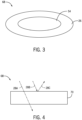
- FIG. 3 and FIG. 4 show examples of arrangements of the reflector assembly 52.
- FIG. 3 is a schematic top view of an example of the reflector assembly 52 in which the retroreflective marker 26 forms a toroid about the transmissive material 54.
- the material 54 at the center portion of the torus can be composed of either a transparent material, an infrared transmissive material of the same wavelength (or frequency) as the retroreflective marker 26 ( ⁇ 850nm-940nm) or transmissive of select other wavelengths (e.g. 1050nm, 1300nm, 1550nm, 1720nm). Additionally, visible light emission can be achieved by implementation of the transmissive material 54 as a transparent or translucent material layer.
- the transmissive material 54 and the retroreflective marker 26 may be coplanar or arranged as adjacent layers (e.g., with the transmissive material 54 adjacent to and beneath or atop the retroreflective marker 26). Further, the transmissive material 54 and the retroreflective marker 26 may be arranged such that their respective cross-sectional areas in the reflector assembly 52 are equal or unequal. In one embodiment, the transmissive material 54 and the retroreflective marker 26 form adjacent halves of the reflector assembly 52.
- FIG. 4 shows a side view of a reflector assembly 52 in which a single material 70 is both retroreflective and transmissive/ transparent at different wavelengths such that the reflector assembly can be transmissive of desired frequencies while reflective of others.
- the reflector assembly 52 may utilize a frequency specific anti reflective (AR) coating or material to enable transmissivity (shown as electromagnetic radiation beam 28a) at select wavelengths (e.g. 1550nm) while enabling reflection (shown as electromagnetic radiation beams 28b, 28c) at other desired wavelengths (e.g. 850nm).
- AR frequency specific anti reflective
- FIGs. 3-4 are shown by way of example, and it should be understood that the reflector assembly 52 can be implemented as a layer or coating and in any shape that maintains the desired level of reflectivity and according to the particular shape and geometry of the interactive object 20.
- the method 80 includes a step of emitting electromagnetic radiation into an area using one or more emitters (block 82).
- a portion of the emitted electromagnetic radiation is harvested by an interactive object in the area and used to activate an integral feedback of the interactive object, such as a special effect (block 84).
- a portion of the emitted electromagnetic radiation is also reflected by a retroreflective material of the interactive object (block 86).
- the location of the interactive object and/or any movement patterns of the interactive object may be detected based on a position of the reflected electromagnetic radiation received by the detector of the system (block 88).
- the controller may monitor a movement pattern of the retroreflective marker, and identify a pattern associated with a particular downstream action.
- certain characteristics of the retroreflective marker may be used by the controller to identify the holder or type of the interactive object, and the downstream action may be selected or activated based on factors including identification information as well as the location and/or movement pattern.
- the downstream action may be activation of an external special effect based on the detected location and/or movement pattern of the interactive object (block 90).
- the interactive object is a sword
- pulling the sword from a wall activates an illumination effect in the sword in concert with associated effects in the wall, such as a pulling noise and changing in shape or color of the wall.
- the wall may be a fixed component of the immersive environment capable of supporting more complex effects, the illumination effect in the sword is retained even when separated from the wall, adding to the illusion.
- the system 10 may operate to selectively activate integral special effects or feedback of an interactive object in conjunction with external special effects.
- the interactive object 20 may include user-specific interactive effects.
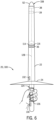
- the interactive object 20, illustrated here as a sword 100 is shown with a reflector assembly 52 positioned at a sword tip 108 and implemented as a point.
- the reflector assembly 52 permits electromagnetic radiation to penetrate through the sword tip 108 so that power can be harvested by the power harvesting device 38.
- the exterior surface 24 of the housing 22 that is not part of the reflector assembly 52 e.g., a grip portion
- the sword 100 has an orientation, such that the sword 100 is passively powered when oriented in a particular manner towards the source of electromagnetic radiation.
- the reflector assembly 52 may form a greater portion (or all) of the exterior surface 24.
- the interactive object 20 may be powered when oriented at a variety of angles relative to the emitter.
- the sword 100 includes the special effect system 36 that controls on board special effects, illustrated here as multiple light sources 114, 116.
- the first light source 114 may be an LED light source of a first color
- the second light source may be an LED light source of a second color.
- the object controller 39 operates to receive control signals to control operation of the special effect system 36 to selectively active the light sources 114, 116 in a particular pattern or order.
- the sword 100 includes an array 124 of individual pressure or grip sensors 126 that provide pressure information (via internal communication leads 128) to the object controller 39.
- the array may be a capacitive or force sensitive resistor array of at least 16 or at least 256 individual sensors.
- the sword 100 may receive sufficient passive power to recognize its matched user and provide a matched user special effect (e.g., green lights, clear tone) that is different than a special effect (e.g., red lights, uncomfortable sound) for a nonmatched user whose grip biometric is different than that of the matcher user.
- a matched user special effect e.g., green lights, clear tone
- a special effect e.g., red lights, uncomfortable sound
- the system 10 may receive facial recognition data (e.g., from the sensor 32 operating as a camera).
- the control unit 18 may activate the emitter 14 to emit the electromagnetic radiation that powers the interactive object 20.
- FIG. 7 illustrates a process flow diagram of a method 150 for powering an interactive object with multiple available special effects. As discussed above, these effects may be selectively activated based on sensors integrated onto the interactive object. Additionally or alternatively, the special effects may be activated based on the location or movement pattern of the interactive object.
- the method 150 includes a step of emitting electromagnetic radiation into an area using one or more emitters (block 152).
- a portion of the emitted electromagnetic radiation is reflected by a retroreflective material of the interactive object and detected (block 154).
- the location of the interactive object and/or any movement patterns of the interactive object may be determined based on the detected portion of the electromagnetic radiation received by the detector of the system (block 158).
- the controller may identify a first movement pattern of the retroreflective marker, and in turn drive the emitter to emit electromagnetic radiation of a first wavelength (block 160).
- the interactive object includes a first power harvesting device that is powered by electromagnetic radiation of the first wavelength, and passive power received by the first power harvesting device in turn causes activation of a first special effect of the interactive object that is coupled to the first power harvesting device (block 162).
- the controller may identify a second movement pattern of the retroreflective marker, and in turn drive the emitter to emit electromagnetic radiation of a second wavelength (block 164).
- the interactive object includes a second power harvesting device that is powered by electromagnetic radiation of the second wavelength, but not the first wavelength. Similarly, the first power harvesting device is not powered by electromagnetic radiation of the second wavelength.
- Passive power received by the second power harvesting device in turn causes activation of a second special effect of the interactive object that is coupled to the second power harvesting device (block 166).
- the external controller Via selective activation or tuning of a wavelength of the emitter, the external controller can influence the activated special effects on the interactive object.
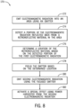
- FIG. 8 illustrates a process flow diagram of a method 170 for powering an interactive object that is triggered by detection of a retroreflective material on the interactive object.
- the method 170 includes a step of emitting electromagnetic radiation into an area using a source, e.g., a first emitter (block 172). A portion of the emitted electromagnetic radiation is reflected by a retroreflective material of the interactive object and detected (block 174). The location of the retroreflective material of the interactive object and/or any movement patterns of the interactive object may be determined based on the detected portion of the electromagnetic radiation received by the detector of the system (block 176).
- the emitter using the same emission source or a different emission source
- the focusing may include estimating a location based on a known spatial relationship between the detected retroreflective material and the transmissive portion of the reflector assembly on the interactive object.
- the emitter emits the focused electromagnetic radiation (block 180) from which power is harvested to activate a special effect (block 182).
- the NIR laser is additionally focused, e.g., aimed and steered to the position of the reflector or an adjusted position on the interactive object, through the use of techniques such as scanning micro mirrors or nonmechanical beam steering methods such as steerable electro-evanescent optical refractor (SEEOR).
- SEEOR steerable electro-evanescent optical refractor
- NIR reflectivity might be desired at the 850nm range for compatibility with existing systems
- a laser emitter intended to provide device power at those frequencies might not be indicated.
- the use of an NIR laser permits higher passive power transmission that has enhanced ability to focus, leading to selective power transmission to one or only some interactive objects within an area while not powering others in the same area.
Landscapes
- Engineering & Computer Science (AREA)
- Physics & Mathematics (AREA)
- Computer Networks & Wireless Communication (AREA)
- Power Engineering (AREA)
- Optics & Photonics (AREA)
- Signal Processing (AREA)
- Multimedia (AREA)
- General Physics & Mathematics (AREA)
- Toxicology (AREA)
- Health & Medical Sciences (AREA)
- Spectroscopy & Molecular Physics (AREA)
- Toys (AREA)
- User Interface Of Digital Computer (AREA)
- Optical Radar Systems And Details Thereof (AREA)
Claims (15)
- Interaktives Objekt (20) zur Verwendung in einer interaktiven Umgebung, das interaktive Objekt umfassend:eine Energiegewinnungsvorrichtung (38), wobei die Energiegewinnungsvorrichtung (38) Energie von elektromagnetischer Strahlung gewinnt;ein Gehäuse (22), innerhalb dessen die Energiegewinnungsvorrichtung (38) eingerichtet ist, das Gehäuse (22) umfassend: eine Reflektoranordnung (52), die die elektromagnetische Strahlung durch einen ersten Abschnitt der Reflektoranordnung (52) an die Energiegewinnungsvorrichtung (38) überträgt und die die elektromagnetische Strahlung von einem zweiten Abschnitt der Reflektoranordnung (52) an einen externen Detektor (16) reflektiert, wobei der erste Abschnitt ein durchlässiges Material umfasst und wobei der zweite Abschnitt ein retroreflektierendes Material umfasst; undein Spezialeffektsystem (36), das mittels der gewonnenen Energie von der Energiegewinnungsvorrichtung (38) mit Energie versorgt wird.
- System (10) des interaktives Objekts zur Verwendung in einer interaktiven Umgebung, das System umfassend:einen Infrarotsender (14), der Infrarotlicht (28) aussendet;das interaktive Objekt (20) nach Anspruch 1;wobei der Detektor (16) reflektiertes Infrarotlicht (28C) von der Reflektoranordnung (52) des interaktiven Objekts (20) detektiert; undeine Steuerung (18), die einen Betrieb des Infrarotsenders (14) steuert und die Daten, die das reflektierte Infrarotlicht (28C) angeben, von dem Detektor (16) empfängt.
- System (10) nach Anspruch 2, wobei das Gehäuse (22) des interaktiven Objekts (20) einen Stab umfasst und wobei die Reflektoranordnung (52) an einer Spitze des Stabs (108) eingerichtet ist.
- System (10) nach Anspruch 2, wobei der Infrarotsender (14) eine erste Infrarotlichtquelle (31), die das Infrarotlicht (28A) in einem ersten Wellenlängenbereich aussendet, und eine zweite Infrarotlichtquelle (31) umfasst, die zusätzliches Infrarotlicht (28B) in einem zweiten Wellenlängenbereich aussendet.
- System nach Anspruch 4, wobei die zweite Infrarotlichtquelle (31) ein Nahinfrarotlaser ist.
- System (10) nach Anspruch 4, wobei die Steuerung (18) programmiert ist, um die zweite Infrarotlichtquelle (31) basierend auf den Daten, die das reflektierte Infrarotlicht (28C) von dem Detektor (16) angeben, zu aktivieren.
- System (10) nach Anspruch 6, wobei die erste Infrarotlichtquelle (31) kontinuierlich aktiv ist.
- System (10) nach Anspruch 2, wobei das reflektierte Infrarotlicht (28C) in einem gleichen Wellenlängenbereich wie das empfangene Infrarotlicht (28A), von dem die optische Energiegewinnungsvorrichtung (38) Energie gewinnt, liegt.
- System (10) nach Anspruch 2, wobei das Spezialeffektsystem (36) eine Vorrichtung (132) für haptisches Feedback umfasst, wobei die Vorrichtung (132) für haptisches Feedback konfiguriert ist, um als Reaktion darauf aktiviert zu werden, dass die optische Energiegewinnungsvorrichtung (38) Energie von dem empfangenen Infrarotlicht (28A) gewinnt.
- System (10) nach Anspruch 2, wobei das Spezialeffektsystem (36) eine Lichtquelle (114, 116) umfasst, die konfiguriert ist, um aktiviert zu werden, um Licht von dem Gehäuse (22) als Reaktion darauf strahlen zu lassen, dass die optische Energiegewinnungsvorrichtung (38) Energie von dem empfangenen Infrarotlicht (28A) gewinnt.
- System (10) nach Anspruch 2, wobei das Spezialeffektsystem (36) umfasst:eine Vielzahl von Sensoren (124, 126), die an der Außenoberfläche des interaktiven Objekts (20) in einer Region, die einem Griffabschnitt entspricht, eingerichtet sind; undeine Objektsteuerung (39), die an oder in dem Gehäuse (22) eingerichtet ist, die programmiert ist zum:Empfangen von Signalen von der Vielzahl von Sensoren (124, 26);Identifizieren eines Griffs eines Benutzers, der das interaktive Objekt (20) hält, basierend auf den Signalen; undErzeugen eines Steuersignals an das Spezialeffektsystem basierend (36) auf dem identifizierten Griff.
- System (10) nach Anspruch 11, wobei das Spezialeffektsystem (36) ferner eine Vorrichtung (132) für haptisches Feedback, eine Lichtquelle (124, 116), oder beides, umfasst, die als Reaktion auf das erzeugte Steuersignal aktiviert werden.
- System (10) nach Anspruch 2, wobei die Reflektoranordnung (52) ein Material (54) umfasst, das für das Infrarotlicht transparent und für sichtbares Licht mindestens teilweise undurchsichtig ist.
- Verfahren zum Aktivieren eines Spezialeffekts eines interaktiven Objekts (20) innerhalb einer interaktiven Umgebung, das Verfahren umfassend:Aussenden (172) erster elektromagnetischer Strahlung, unter Verwendung einer ersten Lichtquelle, in einen Raum hinein;Detektieren (174) der elektromagnetischen Strahlung, die von einem retroreflektierenden Material in dem Raum zurückreflektiert wird, wobei das retroreflektierende Material an einem interaktiven Objekt eingerichtet ist;Bestimmen (176) eines Orts des retroreflektierenden Materials basierend auf der detektierten elektromagnetischen Strahlung; undAussenden (180) zweiter elektromagnetischer Strahlung, unter Verwendung der ersten Lichtquelle oder einer zweiten Lichtquelle, in Richtung des Orts;Gewinnen von Energie von der zweiten elektromagnetischen Strahlung unter Verwendung einer Energiegewinnungsvorrichtung, die in dem interaktiven Objekt eingerichtet ist, wobei eine Reflektoranordnung, die in dem interaktiven Objekt eingerichtet ist, konfiguriert ist, um die zweite elektromagnetische Strahlung an die Energiegewinnungsvorrichtung zu übertragen;Aktivieren (182) eines Spezialeffekts des interaktiven Objekts unter Verwendung der Energie, die von der zweiten elektromagnetischen Strahlung gewonnen wird.
- Verfahren (170) nach Anspruch 14, ferner umfassend ein Fokussieren (178) der zweiten Lichtquelle, um die zweite elektromagnetischen Strahlung basierend auf dem Ort auszusenden, und wobei das Fokussieren der zweiten Lichtquelle das Fokussieren auf einen Abschnitt des interaktiven Objekts (20) basierend auf einer bekannten Beziehung zwischen dem Ort des retroreflektierenden Materials und einer Position eines Materials an dem interaktiven Objekt (20), durch das die zweite elektromagnetische Strahlung hindurchdringt, umfasst, um eine Energiegewinnungsvorrichtung (38) zu erreichen, um den Spezialeffekt des interaktiven Objekts (20) zu aktivieren.
Applications Claiming Priority (3)
| Application Number | Priority Date | Filing Date | Title |
|---|---|---|---|
| US202063010385P | 2020-04-15 | 2020-04-15 | |
| US17/230,132 US12061351B2 (en) | 2020-04-15 | 2021-04-14 | Interactive object systems and methods |
| PCT/US2021/027389 WO2021211783A1 (en) | 2020-04-15 | 2021-04-15 | Interactive object systems and methods |
Publications (2)
| Publication Number | Publication Date |
|---|---|
| EP4135866A1 EP4135866A1 (de) | 2023-02-22 |
| EP4135866B1 true EP4135866B1 (de) | 2024-11-27 |
Family
ID=78081690
Family Applications (1)
| Application Number | Title | Priority Date | Filing Date |
|---|---|---|---|
| EP21723570.4A Active EP4135866B1 (de) | 2020-04-15 | 2021-04-15 | Interaktive objektsysteme und verfahren |
Country Status (8)
| Country | Link |
|---|---|
| US (2) | US12061351B2 (de) |
| EP (1) | EP4135866B1 (de) |
| JP (2) | JP7645280B2 (de) |
| KR (1) | KR20230002741A (de) |
| CN (1) | CN115335128A (de) |
| CA (1) | CA3172630A1 (de) |
| ES (1) | ES3007626T3 (de) |
| WO (1) | WO2021211783A1 (de) |
Families Citing this family (3)
| Publication number | Priority date | Publication date | Assignee | Title |
|---|---|---|---|---|
| US20220223954A1 (en) * | 2021-01-11 | 2022-07-14 | Dus Operating Inc. | Modular battery housing for mounting battery modules to one of a plurality of electric vehicles |
| US20220375324A1 (en) * | 2021-05-24 | 2022-11-24 | Mpics Innovations Pte. Ltd | Sensor device for detecting disinfecting state |
| US20260102716A1 (en) * | 2024-10-03 | 2026-04-16 | Universal City Studios Llc | Interactive object systems and methods |
Family Cites Families (17)
| Publication number | Priority date | Publication date | Assignee | Title |
|---|---|---|---|---|
| GB9415627D0 (en) | 1994-08-01 | 1994-09-21 | Marshall James | Verification apparatus |
| JPH11319332A (ja) * | 1998-05-19 | 1999-11-24 | Taito Corp | Ccdカメラ搭載の鉄道模型システム |
| US7445550B2 (en) | 2000-02-22 | 2008-11-04 | Creative Kingdoms, Llc | Magical wand and interactive play experience |
| US6761637B2 (en) * | 2000-02-22 | 2004-07-13 | Creative Kingdoms, Llc | Method of game play using RFID tracking device |
| JP2002336293A (ja) * | 2001-05-16 | 2002-11-26 | Matsushita Electric Ind Co Ltd | 誘導案内システム |
| WO2003049315A1 (en) * | 2001-12-05 | 2003-06-12 | Walt Disney Parks And Resorts | System and method of wirelessly triggering portable devices |
| US9171454B2 (en) | 2007-11-14 | 2015-10-27 | Microsoft Technology Licensing, Llc | Magic wand |
| US8762734B2 (en) | 2010-02-10 | 2014-06-24 | Raytheon Company | Biometric pressure grip |
| JP5614841B2 (ja) | 2010-12-21 | 2014-10-29 | 株式会社日本総合研究所 | 電子カード使用状況管理システム |
| US20130249301A1 (en) * | 2012-03-21 | 2013-09-26 | Disney Enterprises, Inc., A Delaware Corporation | System And Method For Powering An RFID Module Using An Energy Harvesting Element |
| US9429398B2 (en) | 2014-05-21 | 2016-08-30 | Universal City Studios Llc | Optical tracking for controlling pyrotechnic show elements |
| US10061058B2 (en) | 2014-05-21 | 2018-08-28 | Universal City Studios Llc | Tracking system and method for use in surveying amusement park equipment |
| WO2019057300A1 (en) | 2017-09-22 | 2019-03-28 | Alterface Holdings | METHOD USED BY COMPUTER TO CUSTOMIZE INTERACTIVITY |
| US10614271B2 (en) | 2018-01-15 | 2020-04-07 | Universal City Studios Llc | Interactive systems and methods |
| US10360419B1 (en) | 2018-01-15 | 2019-07-23 | Universal City Studios Llc | Interactive systems and methods with tracking devices |
| US10818152B2 (en) * | 2018-01-15 | 2020-10-27 | Universal City Studios Llc | Interactive systems and methods with feedback devices |
| US10845975B2 (en) * | 2018-03-29 | 2020-11-24 | Universal City Studios Llc | Interactive animated character head systems and methods |
-
2021
- 2021-04-14 US US17/230,132 patent/US12061351B2/en active Active
- 2021-04-15 EP EP21723570.4A patent/EP4135866B1/de active Active
- 2021-04-15 KR KR1020227039829A patent/KR20230002741A/ko active Pending
- 2021-04-15 WO PCT/US2021/027389 patent/WO2021211783A1/en not_active Ceased
- 2021-04-15 CN CN202180028606.4A patent/CN115335128A/zh active Pending
- 2021-04-15 CA CA3172630A patent/CA3172630A1/en active Pending
- 2021-04-15 JP JP2022562469A patent/JP7645280B2/ja active Active
- 2021-04-15 ES ES21723570T patent/ES3007626T3/es active Active
-
2024
- 2024-07-29 US US18/787,756 patent/US20240385355A1/en active Pending
-
2025
- 2025-03-03 JP JP2025032945A patent/JP2025102764A/ja active Pending
Also Published As
| Publication number | Publication date |
|---|---|
| US20240385355A1 (en) | 2024-11-21 |
| US12061351B2 (en) | 2024-08-13 |
| CN115335128A (zh) | 2022-11-11 |
| JP2023522646A (ja) | 2023-05-31 |
| ES3007626T3 (en) | 2025-03-20 |
| CA3172630A1 (en) | 2021-10-21 |
| JP2025102764A (ja) | 2025-07-08 |
| KR20230002741A (ko) | 2023-01-05 |
| WO2021211783A1 (en) | 2021-10-21 |
| EP4135866A1 (de) | 2023-02-22 |
| US20210325580A1 (en) | 2021-10-21 |
| JP7645280B2 (ja) | 2025-03-13 |
Similar Documents
| Publication | Publication Date | Title |
|---|---|---|
| US20240385355A1 (en) | Interactive object systems and methods | |
| US10114452B2 (en) | Motion detection system | |
| US20220214742A1 (en) | User-specific interactive object systems and methods | |
| JP2025134702A (ja) | 特殊光効果システム | |
| KR20230129181A (ko) | 사용자별 상호작용 물체 시스템 및 방법 | |
| US20240233138A9 (en) | Systems and methods for tracking an interactive object | |
| US20240012471A1 (en) | Variable effects activation in an interactive environment | |
| US11762193B2 (en) | Optical tracking system | |
| HK40083365A (en) | Interactive object systems and methods | |
| US11797079B2 (en) | Variable effects activation in an interactive environment | |
| HK40126946A (zh) | 用於跟踪交互式对象的系统和方法 | |
| EP4053677B1 (de) | Augenkontaktdetektionsvorrichtung | |
| HK40100295A (zh) | 用户特定的交互式对象系统和方法 | |
| US20250095163A1 (en) | Systems and methods for tracking an interactive object | |
| HK40082123A (en) | Special light effects system | |
| WO2025064406A1 (en) | Systems and methods for tracking an interactive object | |
| HK40116158A (zh) | 具有跟踪设备的交互式系统和方法 |
Legal Events
| Date | Code | Title | Description |
|---|---|---|---|
| STAA | Information on the status of an ep patent application or granted ep patent |
Free format text: STATUS: UNKNOWN |
|
| STAA | Information on the status of an ep patent application or granted ep patent |
Free format text: STATUS: THE INTERNATIONAL PUBLICATION HAS BEEN MADE |
|
| PUAI | Public reference made under article 153(3) epc to a published international application that has entered the european phase |
Free format text: ORIGINAL CODE: 0009012 |
|
| STAA | Information on the status of an ep patent application or granted ep patent |
Free format text: STATUS: REQUEST FOR EXAMINATION WAS MADE |
|
| 17P | Request for examination filed |
Effective date: 20221014 |
|
| AK | Designated contracting states |
Kind code of ref document: A1 Designated state(s): AL AT BE BG CH CY CZ DE DK EE ES FI FR GB GR HR HU IE IS IT LI LT LU LV MC MK MT NL NO PL PT RO RS SE SI SK SM TR |
|
| DAV | Request for validation of the european patent (deleted) | ||
| DAX | Request for extension of the european patent (deleted) | ||
| GRAP | Despatch of communication of intention to grant a patent |
Free format text: ORIGINAL CODE: EPIDOSNIGR1 |
|
| STAA | Information on the status of an ep patent application or granted ep patent |
Free format text: STATUS: GRANT OF PATENT IS INTENDED |
|
| INTG | Intention to grant announced |
Effective date: 20240624 |
|
| GRAS | Grant fee paid |
Free format text: ORIGINAL CODE: EPIDOSNIGR3 |
|
| GRAA | (expected) grant |
Free format text: ORIGINAL CODE: 0009210 |
|
| STAA | Information on the status of an ep patent application or granted ep patent |
Free format text: STATUS: THE PATENT HAS BEEN GRANTED |
|
| AK | Designated contracting states |
Kind code of ref document: B1 Designated state(s): AL AT BE BG CH CY CZ DE DK EE ES FI FR GB GR HR HU IE IS IT LI LT LU LV MC MK MT NL NO PL PT RO RS SE SI SK SM TR |
|
| REG | Reference to a national code |
Ref country code: GB Ref legal event code: FG4D |
|
| REG | Reference to a national code |
Ref country code: CH Ref legal event code: EP |
|
| REG | Reference to a national code |
Ref country code: DE Ref legal event code: R096 Ref document number: 602021022437 Country of ref document: DE |
|
| REG | Reference to a national code |
Ref country code: IE Ref legal event code: FG4D |
|
| P01 | Opt-out of the competence of the unified patent court (upc) registered |
Free format text: CASE NUMBER: APP_62552/2024 Effective date: 20241123 |
|
| REG | Reference to a national code |
Ref country code: ES Ref legal event code: FG2A Ref document number: 3007626 Country of ref document: ES Kind code of ref document: T3 Effective date: 20250320 |
|
| REG | Reference to a national code |
Ref country code: LT Ref legal event code: MG9D |
|
| REG | Reference to a national code |
Ref country code: NL Ref legal event code: MP Effective date: 20241127 |
|
| PG25 | Lapsed in a contracting state [announced via postgrant information from national office to epo] |
Ref country code: PT Free format text: LAPSE BECAUSE OF FAILURE TO SUBMIT A TRANSLATION OF THE DESCRIPTION OR TO PAY THE FEE WITHIN THE PRESCRIBED TIME-LIMIT Effective date: 20250327 Ref country code: IS Free format text: LAPSE BECAUSE OF FAILURE TO SUBMIT A TRANSLATION OF THE DESCRIPTION OR TO PAY THE FEE WITHIN THE PRESCRIBED TIME-LIMIT Effective date: 20250327 Ref country code: HR Free format text: LAPSE BECAUSE OF FAILURE TO SUBMIT A TRANSLATION OF THE DESCRIPTION OR TO PAY THE FEE WITHIN THE PRESCRIBED TIME-LIMIT Effective date: 20241127 |
|
| PG25 | Lapsed in a contracting state [announced via postgrant information from national office to epo] |
Ref country code: FI Free format text: LAPSE BECAUSE OF FAILURE TO SUBMIT A TRANSLATION OF THE DESCRIPTION OR TO PAY THE FEE WITHIN THE PRESCRIBED TIME-LIMIT Effective date: 20241127 Ref country code: NL Free format text: LAPSE BECAUSE OF FAILURE TO SUBMIT A TRANSLATION OF THE DESCRIPTION OR TO PAY THE FEE WITHIN THE PRESCRIBED TIME-LIMIT Effective date: 20241127 |
|
| PG25 | Lapsed in a contracting state [announced via postgrant information from national office to epo] |
Ref country code: BG Free format text: LAPSE BECAUSE OF FAILURE TO SUBMIT A TRANSLATION OF THE DESCRIPTION OR TO PAY THE FEE WITHIN THE PRESCRIBED TIME-LIMIT Effective date: 20241127 |
|
| PG25 | Lapsed in a contracting state [announced via postgrant information from national office to epo] |
Ref country code: NO Free format text: LAPSE BECAUSE OF FAILURE TO SUBMIT A TRANSLATION OF THE DESCRIPTION OR TO PAY THE FEE WITHIN THE PRESCRIBED TIME-LIMIT Effective date: 20250227 |
|
| PG25 | Lapsed in a contracting state [announced via postgrant information from national office to epo] |
Ref country code: GR Free format text: LAPSE BECAUSE OF FAILURE TO SUBMIT A TRANSLATION OF THE DESCRIPTION OR TO PAY THE FEE WITHIN THE PRESCRIBED TIME-LIMIT Effective date: 20250228 Ref country code: LV Free format text: LAPSE BECAUSE OF FAILURE TO SUBMIT A TRANSLATION OF THE DESCRIPTION OR TO PAY THE FEE WITHIN THE PRESCRIBED TIME-LIMIT Effective date: 20241127 |
|
| PG25 | Lapsed in a contracting state [announced via postgrant information from national office to epo] |
Ref country code: PL Free format text: LAPSE BECAUSE OF FAILURE TO SUBMIT A TRANSLATION OF THE DESCRIPTION OR TO PAY THE FEE WITHIN THE PRESCRIBED TIME-LIMIT Effective date: 20241127 |
|
| PG25 | Lapsed in a contracting state [announced via postgrant information from national office to epo] |
Ref country code: RS Free format text: LAPSE BECAUSE OF FAILURE TO SUBMIT A TRANSLATION OF THE DESCRIPTION OR TO PAY THE FEE WITHIN THE PRESCRIBED TIME-LIMIT Effective date: 20250227 |
|
| PG25 | Lapsed in a contracting state [announced via postgrant information from national office to epo] |
Ref country code: SM Free format text: LAPSE BECAUSE OF FAILURE TO SUBMIT A TRANSLATION OF THE DESCRIPTION OR TO PAY THE FEE WITHIN THE PRESCRIBED TIME-LIMIT Effective date: 20241127 |
|
| PGFP | Annual fee paid to national office [announced via postgrant information from national office to epo] |
Ref country code: DE Payment date: 20250429 Year of fee payment: 5 |
|
| PG25 | Lapsed in a contracting state [announced via postgrant information from national office to epo] |
Ref country code: DK Free format text: LAPSE BECAUSE OF FAILURE TO SUBMIT A TRANSLATION OF THE DESCRIPTION OR TO PAY THE FEE WITHIN THE PRESCRIBED TIME-LIMIT Effective date: 20241127 |
|
| PGFP | Annual fee paid to national office [announced via postgrant information from national office to epo] |
Ref country code: GB Payment date: 20250428 Year of fee payment: 5 Ref country code: ES Payment date: 20250505 Year of fee payment: 5 |
|
| PGFP | Annual fee paid to national office [announced via postgrant information from national office to epo] |
Ref country code: IT Payment date: 20250422 Year of fee payment: 5 |
|
| PG25 | Lapsed in a contracting state [announced via postgrant information from national office to epo] |
Ref country code: EE Free format text: LAPSE BECAUSE OF FAILURE TO SUBMIT A TRANSLATION OF THE DESCRIPTION OR TO PAY THE FEE WITHIN THE PRESCRIBED TIME-LIMIT Effective date: 20241127 |
|
| PGFP | Annual fee paid to national office [announced via postgrant information from national office to epo] |
Ref country code: FR Payment date: 20250425 Year of fee payment: 5 |
|
| PGFP | Annual fee paid to national office [announced via postgrant information from national office to epo] |
Ref country code: CH Payment date: 20250501 Year of fee payment: 5 |
|
| PG25 | Lapsed in a contracting state [announced via postgrant information from national office to epo] |
Ref country code: RO Free format text: LAPSE BECAUSE OF FAILURE TO SUBMIT A TRANSLATION OF THE DESCRIPTION OR TO PAY THE FEE WITHIN THE PRESCRIBED TIME-LIMIT Effective date: 20241127 |
|
| PGFP | Annual fee paid to national office [announced via postgrant information from national office to epo] |
Ref country code: AT Payment date: 20250721 Year of fee payment: 5 |
|
| PG25 | Lapsed in a contracting state [announced via postgrant information from national office to epo] |
Ref country code: SK Free format text: LAPSE BECAUSE OF FAILURE TO SUBMIT A TRANSLATION OF THE DESCRIPTION OR TO PAY THE FEE WITHIN THE PRESCRIBED TIME-LIMIT Effective date: 20241127 |
|
| PG25 | Lapsed in a contracting state [announced via postgrant information from national office to epo] |
Ref country code: CZ Free format text: LAPSE BECAUSE OF FAILURE TO SUBMIT A TRANSLATION OF THE DESCRIPTION OR TO PAY THE FEE WITHIN THE PRESCRIBED TIME-LIMIT Effective date: 20241127 |
|
| REG | Reference to a national code |
Ref country code: DE Ref legal event code: R097 Ref document number: 602021022437 Country of ref document: DE |
|
| PG25 | Lapsed in a contracting state [announced via postgrant information from national office to epo] |
Ref country code: SE Free format text: LAPSE BECAUSE OF FAILURE TO SUBMIT A TRANSLATION OF THE DESCRIPTION OR TO PAY THE FEE WITHIN THE PRESCRIBED TIME-LIMIT Effective date: 20241127 |
|
| PLBE | No opposition filed within time limit |
Free format text: ORIGINAL CODE: 0009261 |
|
| STAA | Information on the status of an ep patent application or granted ep patent |
Free format text: STATUS: NO OPPOSITION FILED WITHIN TIME LIMIT |
|
| 26N | No opposition filed |
Effective date: 20250828 |
|
| PG25 | Lapsed in a contracting state [announced via postgrant information from national office to epo] |
Ref country code: LU Free format text: LAPSE BECAUSE OF NON-PAYMENT OF DUE FEES Effective date: 20250415 |
|
| PG25 | Lapsed in a contracting state [announced via postgrant information from national office to epo] |
Ref country code: MC Free format text: LAPSE BECAUSE OF FAILURE TO SUBMIT A TRANSLATION OF THE DESCRIPTION OR TO PAY THE FEE WITHIN THE PRESCRIBED TIME-LIMIT Effective date: 20241127 |
|
| REG | Reference to a national code |
Ref country code: BE Ref legal event code: MM Effective date: 20250430 |
|
| PG25 | Lapsed in a contracting state [announced via postgrant information from national office to epo] |
Ref country code: BE Free format text: LAPSE BECAUSE OF NON-PAYMENT OF DUE FEES Effective date: 20250430 |
|
| REG | Reference to a national code |
Ref country code: AT Ref legal event code: UEP Ref document number: 1745179 Country of ref document: AT Kind code of ref document: T Effective date: 20241127 |
|
| PG25 | Lapsed in a contracting state [announced via postgrant information from national office to epo] |
Ref country code: IE Free format text: LAPSE BECAUSE OF NON-PAYMENT OF DUE FEES Effective date: 20250415 |