EP4135524B1 - Niederdruckbetäubungsgerät und verfahren zum betäuben eines tieres - Google Patents
Niederdruckbetäubungsgerät und verfahren zum betäuben eines tieres Download PDFInfo
- Publication number
- EP4135524B1 EP4135524B1 EP20931289.1A EP20931289A EP4135524B1 EP 4135524 B1 EP4135524 B1 EP 4135524B1 EP 20931289 A EP20931289 A EP 20931289A EP 4135524 B1 EP4135524 B1 EP 4135524B1
- Authority
- EP
- European Patent Office
- Prior art keywords
- stunning rod
- passageway
- catch
- piston
- rod chamber
- Prior art date
- Legal status (The legal status is an assumption and is not a legal conclusion. Google has not performed a legal analysis and makes no representation as to the accuracy of the status listed.)
- Active
Links
Images


Classifications
-
- A—HUMAN NECESSITIES
- A22—BUTCHERING; MEAT TREATMENT; PROCESSING POULTRY OR FISH
- A22B—SLAUGHTERING
- A22B3/00—Slaughtering or stunning
- A22B3/02—Slaughtering or stunning by means of bolts, e.g. slaughtering pistols, cartridges
Definitions
- This invention relates in general to a pneumatic animal stunner used in livestock/slaughterhouse operations. More specifically, this invention relates to a pneumatic animal stunner having a housing with a catch piston chamber, a stunning rod chamber, a supply passageway, a stunning rod slideable within the stunning rod chamber, a catch for holding and releasing the stunning rod, a catch piston disposed adjacent the catch, a first passageway for permitting airflow to a rearward end of the stunning rod chamber, and a second passageway for permitting airflow to a forward end of the stunning rod chamber.
- the invention further relates to a method of stunning an animal utilizing the pneumatic animal stunner identified above and delineated in claims 1-9.
- Pneumatic stunners that provide for automatic retraction of the stunning rod typically have complex valve systems that are more difficult to manufacture and tend to add to the cost of the stunner. Such valve systems also tend to add to weight to the device, which may increase operator fatigue. Additional issues involve the requirement of supplying the pressurized fluid at relatively high pressures, typically in the range of 175 - 220 psi (1.3 - 1.6 MPa). Portable stunners are generally lighter in weight, but after firing often require manual retraction of the stunning rod, also adding to operator fatigue.
- an animal stunner used in livestock/slaughterhouse operations teaches a piston slideable within an inner chamber, and a fire pressure chamber within an annular configuration disposed adjacent a rearward or central end of the inner chamber.
- a valve system alternately controls flow of the pressurized fluid from the fire pressure chamber to the rearward end of the inner chamber to move the piston and drive the stunning rod.
- the present invention utililzes reduced pressure of the pressurized fluid needed for operation, and has reduced complexity in valve and venting systems.
- a pneumatic animal stunner as set out in the appended set of claims 1-9, which includes a housing having a catch piston chamber, a stunning rod chamber, a supply passageway disposed in the housing between a source of pressurized fluid and the catch piston chamber, a catch mounted within the housing for alternately holding and releasing the stunning rod, and a catch piston disposed adjacent the catch and in sliding contact within the catch piston chamber, the catch piston being adapted to move between a first position urging the catch to hold and prevent the stunning rod from being driven forward, and a second position permitting the catch to release and permit the stunning rod to be driven forward.
- a first passageway in the catch piston permits air to flow from the source of pressurized fluid through the first passageway to a rearward end of the stunning rod chamber.
- a second passageway in the catch piston permits air to flow from the source of pressurized fluid through the second passageway to a forward end of the stunning rod chamber.
- the present invention is also directed to a method of stunning an animal.
- the method provides for a pneumatic animal stunner according to claims 1-9.
- the method includes the steps according to claims 10-13, including: moving the catch piston into the first position urging the catch to hold and prevent the stunning rod from being driven forward, moving the catch piston towards the second position to release the catch, causing pressurized fluid to flow from the source through the first passageway into the rearward end of the stunning rod chamber to drive the stunning rod forward upon release of the catch to stun the animal, and, upon movement of the catch piston into the second position, flowing pressurized fluid from the source through the second passageway into the forward end of the stunning rod chamber to drive the stunning rod rearward.
- the invention also relates to a catch piston according to claim 14 for use in opening and closing catches in such a pneumatic animal stunner.
- the method further provides a resilient annular cushion disposed at a front end of the stunning rod chamber, and an internal passageway .
- the method further includes the step of causing pressurized fluid to flow through the internal passageway into the forward end of the stunning rod chamber between the pair of resilient annular cushions to drive the stunning rod rearward.
- the stunner 20 includes an outer elongated hollow housing 22, a head contact activator 18 moveable within an outer housing nose 23, a front end 24, a tail end 26, a stunning rod 40 moveable forward and rearward about longitudinal axis 80 and catches 60 arrayed about longitudinal axis 80 for holding and releasing the stunning rod 40.
- the stunner is grasped by a main handle 28 extending below body 22 and a rear handle 29 extending from tail end 26.
- Housing 22 includes within it a generally cylindrical inner pressure or stunning rod chamber 30 for the stunning rod and piston and a surrounding firing chamber 32 to receive and hold a pressurized fluid.
- a circular stunning rod piston 48 surrounded by an O-ring seal 49 slides along the inner cylindrical surface of inner chamber 30 within housing 22. Piston 48 moves forward and rearward along axis 80, and carries stunning rod 40. In the embodiment shown the stunning rod and piston are formed integrally of one piece, but they may be separate components secured together.
- An annular firing chamber 32 surrounds inner chamber 30 within housing 22 and is open at the rear, so that air can move freely and quickly from firing chamber 32 to the region of inner chamber 30 behind piston 48 upon firing of the stunner, as explained further below. Nose rear wall 27 at front of chamber 30 limits forward motion of piston 48 and stunning rod 40, and carries a pair of resilient annular cushions 25a, 25b.
- the rearward end 41 of stunning rod 40 has an opening with an inward lip 46 extending about its periphery, which lip is alternately held and released by an outwardly extending flange 64 at the forward end of catch 60.
- the body or shaft of stunning rod 40 may be circular or non-circular in shape as viewed in cross-section normal to the longitudinal axis.
- the forward or striking end 44 of the stunning rod extends in a sliding fit through a correspondingly configured opening 17 in head contact activator 18 at the front of housing 22 to be driven toward the animal's head when the catch releases the stunning rod lip 46.
- the stunning rod forward end 44 is sized with a diameter and configuration either to penetrate, or prevent penetration of (i.e. concuss), the animal's head.
- the example shown in Figs. 1-5C is of a penetrating rod.
- the catch system for holding and releasing the stunning rod as shown in the embodiment is disposed rearward of stunning rod chamber 30 in the rear of housing 22.
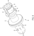
- Catches 60 are further shown in Figs. 8-11C and in the embodiment shown are three (3) arcuate catches arrayed around axis 80.
- Each catch may have a body curved in an arc segment about the longitudinal axis, with outwardly extending flanges 64 and 66 at the front and rear ends, respectively.
- Each catch 60 in the embodiment shown has an arc of more than 90° and less than 120° so that three catches may be arranged cylindrically about the longitudinal axis 80 with sufficient space between adjacent catches to pivot inwardly without interfering with one another. Fewer or more than three catches may be employed.
- a generally hollow cylindrical catch retainer 70 extends forward from the rear end of housing 22.
- the front portion of catch retainer 70 extends over and around, and secures the rearward end portions of catches 60.
- the catch retainer 70 has at its forward end an inwardly facing groove, which receives the catch rear end flanges 66 extending on a side away from axis 80.
- Catch release piston 50 slides within a central opening in catch cylinder 75 (see also Fig. 6 ) disposed on stunner tail end 26 and a front portion is slidingly received within the central opening of retainer 70 and moves forward and rearward along axis 80, as shown in cross-section in Figs. 1-4 .
- Catch piston 50 has circular release piston portion 52 sliding within a cylindrical catch piston chamber 72 behind the rear portion of catch retainer 70.
- Catch release piston 50 has a central opening 58 extending along axis 80 to forward end 51, and forward of release piston portion 52 catch release piston 50 has a generally cylindrical body portion within and contacting the rearward ends of catches 60 (see also Figs. 8 and 9A-9C ).
- the support provided to the catch rear end portions by the inner catch piston body and the outer catch retainer permits the catches 60 to rotate and their forward end flanges 64 to pivot inwardly and outwardly around rearward end flanges 66 in the retainer 70 groove.
- catch piston 50 has a forward end portion 51 within the catches which has a diameter sufficient to contact and urge catch forward end portion flanges 64 outward into engagement with the stunning rod opening lip 46.
- the catch piston Rearward of the forward end portion 51 the catch piston has a relief portion 56 with a diameter smaller than the forward end portion diameter. This relief portion diameter is sufficiently small to permit catch forward end portion 64 to move freely inward to the release position, with flanges 64 out of engagement with the stunning rod opening lip 46.
- catch piston 50 When catch piston 50 is moved forward from the first, hold position to the second, release position, catch front ends 51 are no longer in a position to prevent catch front end 64 from moving inward.
- the rearward sides of front flanges 64 are beveled 65 at an angle greater than 90° with the catch body 62 (see also Figs.
- Stunner 20 is operable by pressurized fluid, such as compressed air or any other suitable fluid.
- compressed air is the fluid and is supplied from a hose or line connected to an air compressor. Air pressure and flow may be controlled by a regulator (not shown) and the compressed air flows through into inlet 82 in housing 22, rearward of main handle 28.
- Flow of the pressurized air is then split after inlet 82, between internal passageway 84 and trigger supply passageway 92.
- Internal passageway 84 communicates with catch release piston 50, and the terminus of the passageway may encircle the piston, and trigger supply passageway 92 communicates with main valve 114 operated by trigger 110 in handle 28.
- a spring (not shown) in valve 114 urges the valve into a first, downward position, and urges the trigger to the undepressed position.
- a first passage 112a in main valve 114 permits air to flow from trigger supply passageway 92 to supply passageway 94, in communication with catch piston cylinder chamber 72.
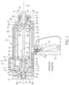
- catch release piston 50 When the pressurized fluid source is connected via inlet 82, catch release piston 50 is locked in the first, rearward hold position, supply trigger 110 is undepressed, and stunner 20 is in a neutral state, as shown in Fig. 1 .
- One or more first radial passageways 85 extend through the body of catch piston 50 from the periphery to catch piston central opening 58, and passageways 84 and 85 are aligned when catch piston 50 is rearward in the hold position.
- pressurized air may flow freely from passageway 84 through passageway 85, through central opening 58 and forward within stunning rod lip 46 to inner chamber 30, behind stunning rod piston 48, and through the open rear end into firing chamber 32 around the inner chamber.
- alignment of the first slot 112a in main valve 114 in the trigger 110 undepressed position allows pressurized air to flow through supply passageway 94 to catch piston cylinder chamber 72 forward of the catch release piston portion 52 and rearward of catch retainer 70, urging catch piston 50 rearward.
- This constant pressure holding catch piston 50 is maintained so long as trigger 110 remains undepressed, which ensures the stunning rod 40 does not fire accidentally in the event the stunner is dropped or otherwise mishandled.
- Catch piston 50 includes in its body a second passageway 89, rearward of the first passageway 85, which in the embodiment shown comprises an open-top slot in the outer wall of catch piston 50 extending around all or a portion of the circumference of the catch piston.
- second passageway 89 is aligned with passageways 90a and 90b, whose ends encircle the catch release piston and are connected, and vent to atmosphere.
- Second passageway 89 is also aligned with passageway 104, and encircles the chamber, and which extends forward from catch release piston chamber 71 to the forward end of inner chamber 30 and in communication with one or more openings 34 alongside and between cushions 25a, 25b.
- Rearward of second passageways 89, third radial passageways 87 extend from central opening 58 to the periphery of the catch piston 50 body.
- Pressurized fluid from the rear of firing chamber 32 exerts a force against stunning rod piston 48, which is held from forward movement only by the position of catch flanges 64 retaining stunning rod rear lip 46.
- an embodiment of the present invention employs main trigger 110, controlling main handle valve 114, in combination with head contact activator 18.
- a head activator chamber passageway 96 extends through the handle and housing from main valve 114 forward to head contact activator 18.
- a passageway 102 extends rearward from head contact activator 18 to the back end of catch piston cylinder chamber 72. Passageway 102 does not intersect with passageway 104.
- the head contact 18 slides fore and aft within nose 23 forward of chamber 98 (see also Fig. 13 ) and is extended by spring (not shown) pressure toward a forward (rightward) position.
- the rear portion or cylindrical projection 118 of the head activator 18 extends partially through the opening in the nose rear wall 27 at the rear of the activator chamber 98, and within the opening of forward cushion 25a.
- a head contact passageway 106 comprises a slot extending around the periphery of the cylindrical body 120 of head contact 18. When trigger 110 is undepressed, head contact slot 106 is not aligned with passageway 96, and a second passage 112b in valve 114 aligns to vent any air in head activator passage 96 to atmosphere through an opening in the handle 28.
- head contact passageway 106 When head contact 18 is in the forward position, head contact passageway 106 is aligned with both passageway 102 and head contact vent 19, and when the catch release piston 50 is in the rearward position, catch piston slot 89 is aligned with both passageway 104 and vent passageway 90b, so that the rearward end of catch piston cylinder chamber 72 vents through the front of housing 22, via vent 19, and the forward end of inner chamber 30 vents through the rear of housing 22, via vent 90b, as shown in Fig. 1 . The stunner will not fire in this position, wherein main trigger 110 and head contact 18 are not depressed.
- a second or auxiliary trigger 116 may be provided to open and close flow though passageway 102, which also must be depressed to open passageway 102 and actuate the stunning rod, as discussed further below. Installation of this optional auxiliary trigger 116 may require passageway 102 to be accessed at a point closer to the tail end 26 of the housing to allow for this added safety feature, with no additional change to the flowpath of passageway 102 as shown in Figs. 1-4 being required.
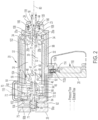
- the main handle valve 114 is activated by the operator depressing main trigger 110 with one hand against the force of the spring in the valve, and head contact 18 is activated by the operator pressing against the animal's head to move and depress the contact 18 rearward (leftward) in the direction shown by the arrows against the force of the head contact spring, as shown in Fig. 2 , so the rear portion of the head activator 18 moves further into the opening in the rear of the activator chamber 98.
- valve 114 first passageway 112a connects passageway 94 with the handle vent opening and pressurized air from the forward end of catch piston cylinder chamber 72 is exhausted to the atmosphere
- valve 114 second passageway 112b connects passageway 92 to passageway 96 to provide pressurized air from inlet 82 to head contact activator 18. Since head contact 18 is in the rearward position, head contact slot 106 aligns with head activator passageway 96 and permits communication between passageways 96 and 102. Compressed air then flows via passageway 102 to the rearward end of catch piston cylinder chamber 72. If the optional auxiliary trigger 116 is used, it must be depressed to open the valve to permit pressurized air flow through passageway 102.
- catch release piston 50 is moved by the compressed air in the rear of chamber 72 and begins to extend forward (rightward) to its limit, against catch retainer 70. This forward movement of end 51 releases catches 60 and permits inward retraction of forward catch latches 64 to relief portion 56.
- stunning rod lip 46 is urged forward and moves against the catch beveled flange surfaces 65, moving catch forward end flanges inward and releasing stunning rod 40.
- Fig. 2 shows the catch piston in an intermediate position as it is moved forward from the first, hold position toward the second, release position.
- Passageway 85 has moved out of alignment from passageway 84, and passageway 84 is consequently closed to prevent the pressurized fluid from flowing from inlet 82.
- operation of valve 114 by depressing the supply trigger does not permit further pressurized fluid to flow from the source into either the inner stunning rod chamber 30 or firing chamber 32 because of the misalignment of supply passageway 84 and catch piston first passageway 85. Because the catch piston 50 has begun to be moved forward toward its second release position, the second passageway slot 89 is not yet aligned with supply passageway 84.
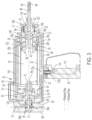
- FIG. 3 shows the animal stunner 20 with the stunning rod 40 in the full forward, end-of-stroke position.
- piston 48 contacts cushion 25b, and both cushions 25b and 25a at the forward end of stunning rod chamber 30 compress to cause forward motion of piston 48 and rod 40 to decelerate and stop within the stunning rod chamber.
- the stunning rod striking end 44 is now fully extended through head contact opening 17.
- pressurized fluid continues to flow from the source through the supply passageway 84, through the slot 89 extending around the catch piston 50 and into internal passageway 104 and through openings 34 into the forward end of the stunning rod chamber 30 at cushions 25a, 25b ahead of stunning rod piston 48.
- a portion of the pressurized air flows from the front of stunning rod chamber 30 through a passageway comprising one or more small slots 108 between the rear portion or projection 118 of the head contact activator 18 and the opening in nose rear wall 27 at the rear of the activator chamber 98, which pressurized air along with the spring assist moves the head contact 18 fully forward to its deactivated position.
- slots 108 may be formed in or around the opening in nose rear wall 27 ( Fig. 3 )
- the embodiment shown in Figs. 12A and 12B for the head contact 18 shows slots 108 comprising four (4) slots or grooves arrayed around and formed in the periphery of the rear portion or projection 118 of the head contact activator.
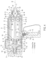
- third radial passageways 87 are in alignment with vent passageways 90a, 90b, and permit air behind piston 48 to flow through catch piston central opening 58 and vent to atmosphere out of housing rear portion 26. Pressurized air being supplied from passageway 104 to the forward end of stunning rod chamber 30 acts against stunning rod piston 48 to begin to drive it rearward.
- the pressurized air in chamber 30 forward end retracts the stunning rod 40 rearward (leftward; as shown by the arrow) until lip 46 of stunning rod 40 passes behind the front flanges 64 of catches 60, and stunning rod rear end 41 contacts the forward end 51 of catch piston 50. Because catch piston cylinder chamber 72 is fully vented fore and aft of catch release piston portion 52, as stunning rod piston strikes forward end 51, catch release piston 50 is free to begin to move back from the second, forward position toward the first, hold position.
- the catch piston second passageway 89 moves out of alignment with air supply passageway 84
- third passageway 87 moves out of alignment with vent passageways 90a, 90b
- catch piston first passageway 85 is not yet in alignment with the air supply passageway 82.
- Trigger 110 may be released by the operator, and in its undepressed position as shown in Fig.
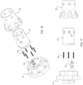
- FIG. 14-17 An alternate embodiment of a nose 23' and a head contact activator 18' disposed on a front end 14' of an animal stunner 20' and sized to receive a larger stunning rod 40' having a larger striking end 44' is presented in Figs. 14-17 .
- This particular nose and head contact configuration is for use in the animal stunner 20' embodiment constructed to prevent penetration of (i.e. concuss) an animal's head, as previously described.
- the head contact 18' slides fore and aft within nose 23' forward of chamber 98' and is biased by a spring 130 pressure toward a forward (rightward) position.
- a nose valve 132 is disposed within the nose 23' and is interactive via the sliding motion of the head contact 18'.
- a cylindrical projection 118' of the head contact activator 18' extends partially through the opening in the front end of the nose 23', and is disengaged with the nose valve 132. The stunner will not fire in this position, wherein main trigger 110 and head contact 18' are not depressed.
- the main handle valve 114 is activated by the operator depressing the main trigger 110 with one hand (and optionally auxiliary trigger 116 with the other hand) against the force of the spring in the valve 114, and nose valve 132 is activated by the operator pressing the head contact 18' against the animal's head to move and depress the head contact 18' rearward (leftward) against the force of the springs 130, as shown in Fig. 15 , such that a head contact tab 18a' extending from the rear portion of the head contact 18' engages with the nose valve 132 to activate it and allow for the passage of fluid.
- the larger striking end 44' of the stunning rod 40' used in the stunner 20' has a larger diameter than that of its penetrating counterpart 44 as previously described.
- This striking end 44' is affixed to the end of the rod 40' by a bolt, screw, nail, or other acceptable fastening means.
- the inner diameter of head contact 18' conforms to this striking end 44' diameter to allow for a sliding fit, such that the rod does not rattle or otherwise displace itself during the firing sequence.
- the stunner and its components may be made of steel, aluminum, composite or other suitable materials.
- the stunning rod may be constructed as described in U.S. Patent No. 10,258,051 titled "LIGHTWEIGHT STUNNING ROD".
- the construction of the stunner shown is sufficiently robust so that it will avoid accidental firing if dropped by the operator.
- the present invention therefore provides a pneumatic animal stunner and method of use that has one or more of the following advantages: 1) reduction in the complexity of valve and venting systems; 2) reduced cost to manufacture the stunner; 3) reduction in weight of an automatically retracting stunner; 4) reduced operator fatigue in using the stunner; 5) reduced pressure of the pressurized fluid needed to operate the stunner, which may be below 175 psi (1.3 MPa) and as low as about 125 psi (1 MPa) and rugged construction to avoid accidental firing and damage.
Landscapes
- Life Sciences & Earth Sciences (AREA)
- Engineering & Computer Science (AREA)
- Food Science & Technology (AREA)
- Actuator (AREA)
- Infusion, Injection, And Reservoir Apparatuses (AREA)
- Catching Or Destruction (AREA)
- Fluid-Damping Devices (AREA)
Claims (15)
- Ein pneumatisches Tierbetäubungsgerät (20), das folgendes aufweist:ein Gehäuse (22), mit einer Kolbenfangkammer (72), einer Betäubungsstabkammer (30) und einem vorderen Ende (24) vor der Betäubungsstabkammer,einen Versorgungskanal (92) in dem Gehäuse (22) zwischen einer Druckfluidquelle und der Kolbenfangkammer;ein Betäubungsstab (40), der in der Betäubungsstabkammer (30) verschiebbar ist und entlang einer Längsachse (80) in Richtung des vorderen Endes (24) des Gehäuses und aus diesem heraus betätigbar ist;eine innerhalb des Gehäuses angebrachte Sperrklinke (60) zum abwechselnden Halten und Freigeben des Betäubungsstabs;einen benachbart zu der Sperrklinke und in Gleitkontakt innerhalb der Kolbenfangkammer angeordneten Sperrklinkenbetätigungskolben (50), wobei der Sperrklinkenbetätigungskolben dazu ausgebildet ist, sich zwischen einer ersten Position, in der er die Sperrklinke dazu drängt, den Betäubungsstab zu halten und dessen Vorwärtsfahren zu verhindern, und einer zweiten Position, in der er es der Sperrklinke ermöglicht, den Betäubungsstab freizugeben und dessen Vorwärtsfahren zuzulassen, zu bewegen;einen ersten Kanal (85) im Sperrklinkenbetätigungskolben, der mit dem Versorgungskanal des Gehäuses fluchtet, wenn sich der Sperrklinkenbetätigungskolben in der ersten Position befindet, wodurch Luft von der Quelle des unter Druck stehenden Fluids durch den ersten Kanal zu einem hinteren Ende der Betäubungsstabkammer strömen kann; undeinen zweiten Kanal (89) im Sperrklinkenbetätigungskolben, der mit dem Versorgungskanal fluchtet, wenn sich der Sperrklinkenbetätigungskolben in der zweiten Position befindet, wodurch Luft von der Quelle des unter Druck stehenden Fluids durch den zweiten Kanal zu einem vorderen Ende der Betäubungsstabkammer strömen kann;wobei, wenn sich der Sperrklinkenbetätigungskolben in der ersten Position befindet, unter Druck stehendes Fluid von der Quelle durch den Versorgungskanal und den ersten Kanal in das hintere Ende der Betäubungsstabkammer strömen kann, um den Betäubungsstab beim Lösen der Sperrklinke nach vorne zu betätigen und wenn sich der Sperrklinkenbetätigungskolben nach dem Lösen der Sperrklinke in der zweiten Position befindet, kann das unter Druck stehende Fluid von der Quelle durch den Versorgungskanal und den zweiten Kanal in das vordere Ende der Kammer des Betäubungsstabs strömen, um den Betäubungsstab nach hinten zu betätigen.
- Pneumatisches Tierbetäubungsgerät nach Anspruch 1, wobei, wenn sich der Sperrklinkenbetätigungskolben (50) nach dem Lösen der Sperrklinke (60) in der zweiten Position befindet, das unter Druck stehende Fluid von der Quelle durch den Zufuhrkanal (92) und den zweiten Kanal (89) in das vordere Ende der Kammer des Betäubungsstabs strömen kann, um den Betäubungsstab (40) nach hinten zu bewegen und den Sperrklinkenbetätigungskolben (50) wieder in die erste Position zu bewegt, wodurch die Sperrklinke gedrückt wird, um zu verhindern, dass der Betäubungsstab nach vorne bewegt wird, und insbesondere einen Betäubungsstabkolben (48), der an dem Betäubungsstab angeordnet ist und in der Betäubungsstabkammer verschiebbar ist, und ein Paar von Polstern (25a, b) an einem vorderen Ende der Betäubungsstabkammer, um das Stoppen des Betäubungsstabs und des Betäubungsstabkolbens abzufedern, wenn der Betäubungsstabkolben die Vorderseite der Betäubungsstabkammer erreicht und/oder ein interner Kanal im Gehäuse, der sich von der Kolbenfangkammer zur Vorderseite der Betäubungsstabkammer zwischen dem Polsterpaar erstreckt, und wobei, wenn sich der Sperrklinkenbetätigungskolben in der zweiten Position befindet, das unter Druck stehende Fluid von der Quelle durch den zweiten Kanal im Sperrklinkenbetätigungskolben und den internen Kanal in das vordere Ende der Betäubungsstabkammer zwischen dem Polsterpaar strömen kann, um den Betäubungsstab nach hinten zu bewegen.
- Pneumatisches Tierbetäubungsgerät nach Anspruch 1, ferner folgendes aufweisend: ein Hauptventil (114) zum Ein- und Ausschalten im Gehäuse, um den Fluss des unter Druck stehenden Fluids von der Quelle zum Versorgungskanal zu steuern.
- Pneumatisches Tierbetäubungsgerät nach Anspruch 1, wobei der Sperrklinkenbetätigungskolben einen zentralen Kanal aufweist und wobei sich der erste Kanal (85) von dem zentralen Kanal zu dem Versorgungskanal (92) erstreckt, wenn sich der Sperrklinkenbetätigungskolben in der ersten Position befindet, um unter Druck stehendes Fluid durch den zentralen Kanal zum hinteren Ende der Kammer des Betäubungsstabs zuzuführen, und insbesondere ein dritter Kanal (87) im Sperrklinkenbetätigungskolben, der es ermöglicht, dass Luft vom hinteren Ende der Kammer des Betäubungsstabs durch den zentralen Kanal des Sperrklinkenbetätigungskolbens und in die Atmosphäre strömt, während der Betäubungsstab nach hinten bewegt wird.
- Pneumatisches Tierbetäubungsgerät nach Anspruch 1, wobei der zweite Kanal (89) des Sperrklinkenbetätigungskolbens folgendes aufweist: einen Schlitz in einer Außenwand des Sperrklinkenbetätigungskolbens, der mit dem Zufuhrkanal fluchtet, wenn sich der Sperrklinkenbetätigungskolben (50) in der zweiten Position befindet, wodurch ein unter Druck stehendes Fluid von der Quelle durch den Zufuhrkanal und den Schlitz zu einem vorderen Ende der Betäubungsstabkammer strömen kann, oder einen internen Kanal (84) im Gehäuse, der sich von der Kolbenfangkammer zur Vorderseite der Betäubungsstabkammer erstreckt, und wobei der zweite Kanal des Sperrklinkenbetätigungskolbens einen Schlitz in einer Außenwand des Sperrklinkenbetätigungskolbens aufweist, der mit dem Zufuhrkanal und dem internen Kanal fluchtet, wenn sich der Sperrklinkenbetätigungskolben in der zweiten Position befindet, damit unter Druck stehendes Fluid von der Quelle durch den Zufuhrkanal, den Schlitz im Sperrklinkenbetätigungskolben und den internen Kanal in das vordere Ende der Kammer für den Betäubungsstab strömt, um den Betäubungsstab nach hinten zu bewegen.
- Pneumatisches Tierbetäubungsgerät nach Anspruch 1, ferner aufweisend einen Kopfkontakt (18) am vorderen Ende des Gehäuses, der zwischen einer deaktivierten Position und einer das Tier berührenden Position bewegbar ist, wobei der Kopfkontakt in der das Tier berührenden Position einen Luftstrom aus dem Versorgungskanal zulässt, um den Sperrklinkenbetätigungskolben aus der ersten Position in die zweite Position zu bewegen.
- Pneumatisches Tierbetäubungsgerät nach Anspruch 1, folgendes aufweisend:einen Betäubungsstabkolben (48), der an dem Betäubungsstab (40) angeordnet ist und in der Betäubungsstabkammer verschiebbar ist;mindestens ein elastisches Polster (25), das an einer Vorderseite der Betäubungsstabkammer angeordnet ist, um das Stoppen des Betäubungsstabs und des Betäubungsstabkolbens abzufedern, wenn der Betäubungsstabkolben die Vorderseite der Betäubungsstabkammer erreicht; undeinen internen Kanal (84) im Gehäuse, um unter Druck stehendes Fluid von einer Quelle für unter Druck stehendes Fluid zur Vorderseite der Betäubungsstabkammer entlang des mindestens einen elastischen Polsters zuzuführen, wobei unter Druck stehendes Fluid von der Quelle abwechselnd durch den Versorgungskanal in das hintere Ende der Betäubungsstabkammer strömt, um den Betäubungsstab nach vorne zu bewegen, und durch den internen Kanal in das vordere Ende der Betäubungsstabkammer entlang des mindestens einen elastischen Polsters strömt, um den Betäubungsstab nach hinten zu bewegen.
- Pneumatisches Tierbetäubungsgerät nach Anspruch 7, welches folgendes aufweist: ein Paar elastischer ringförmiger Polster (25a, b), die an einer Vorderseite der Betäubungsstabkammer angeordnet sind, und wobei der innere Kanal eine Öffnung an der Vorderseite der Betäubungsstabkammer zwischen den elastischen ringförmigen Polstern aufweist.
- Pneumatisches Tierbetäubungsgerät nach Anspruch 1, folgendes aufweisend:einen Betäubungsstabkolben, der am Betäubungsstab angeordnet und in der Betäubungsstabkammer verschiebbar ist;einen Kopfkontakt (18) am vorderen Ende des Gehäuses mit einem hinteren Abschnitt, der sich durch eine Öffnung im vorderen Ende der Betäubungsstabkammer erstreckt, wobei der Kopfkontakt zwischen einer deaktivierten Position und einer Position, in der er das Tier berührt, bewegbar ist, wobei der Kopfkontakt in der deaktivierten Position den Fluss von unter Druck stehendem Fluid von der Quelle zum hinteren Ende der Betäubungsstabkammer blockiert, wobei der Kopfkontakt in der Position, in der er das Tier berührt, den Fluss von Luft vom Versorgungskanal ermöglicht, um den Sperrklinkenbetätigungskolben von der ersten Position in die zweite Position zu bewegen;einen internen Kanal (84) im Gehäuse, um unter Druck stehendes Fluid von einer Quelle für unter Druck stehendes Fluid zur Vorderseite der Betäubungsstabkammer zu leiten; undeinen Kanal zwischen dem hinteren Abschnitt des Kopfkontakts und der Öffnung im vorderen Ende der Kammer des Betäubungsstabs, wobei, wenn sich der Kopfkontakt in der Position befindet, in der er das Tier berührt, unter Druck stehendes Fluid von der Quelle durch den Zufuhrkanal in das hintere Ende der Kammer des Betäubungsstabs strömen kann, um den Betäubungsstab nach vorne zu bewegen, und wenn das unter Druck stehende Fluid durch den internen Kanal in das vordere Ende der Kammer des Betäubungsstabs strömt, um den Betäubungsstab nach hinten zu bewegen, strömt ein Teil des unter Druck stehenden Fluids durch den Kanal zwischen dem hinteren Abschnitt des Kopfkontakts und der Öffnung im vorderen Ende der Betäubungsstabkammer, um den Kopfkontakt in die deaktivierte Position zu bewegen, wodurch der Fluss des unter Druck stehenden Fluids von der Quelle zum hinteren Ende der Betäubungsstabkammer blockiert wird, und wobei insbesondere der Kopfkontakt einen hinteren Vorsprung aufweist, der sich durch die Öffnung in einem vorderen Ende erstreckt und der Kanal zwischen dem hinteren Abschnitt des Kopfkontakts und der Öffnung im vorderen Ende der Kammer für den Betäubungsstab folgendes aufweist: mehrere Schlitze, die in einem Umfang des hinteren Vorsprungs des Kopfkontakts ausgebildet sind, und/oder mindestens ein elastisches Polster, das an einem vorderen Ende der Kammer für den Betäubungsstab angeordnet ist, um den Betäubungsstab und den Betäubungsstabkolben abzufedern, wenn der Betäubungsstabkolben die Vorderseite der Betäubungsstabkammer erreicht; undeinen internen Kanal im Gehäuse, um unter Druck stehendes Fluid von einer Quelle für unter Druck stehendes Fluid zur Vorderseite der Betäubungsstabkammer entlang des mindestens einen elastischen Polsters zu leiten, wobei unter Druck stehendes Fluid von der Quelle abwechselnd durch den Versorgungskanal in das hintere Ende der Betäubungsstabkammer strömt, um den Betäubungsstab nach vorne zu bewegen, und durch den internen Kanal in das vordere Ende der Betäubungsstabkammer entlang des mindestens einen elastischen Polsters strömt, um den Betäubungsstab nach hinten zu bewegen.
- Verfahren zum Betäuben eines Tieres, das folgendes aufweist:zur Verfügung stellen eines pneumatischen Tierbetäubungsgerätes (20) gemäß mindestens einem der vorhergehenden Ansprüche;Bewegen des Sperrklinkenbetätigungskolbens (50) des pneumatischen Tierbetäubungsgerätes in die erste Position, wobei die Sperrklinke gedrückt wird, um die Betäubungsstange (40) zu halten und zu verhindern, dass sie nach vorne bewegt wird;Bewegen des Sperrklinkenbetätigungskolbens (50) in Richtung der zweiten Position, um die Sperrklinke (60) freizugeben;Auslösen, dass das unter Druck stehende Fluid von der Quelle durch den ersten Kanal (85) in das hintere Ende der Betäubungsstabkammer strömt, um den Betäubungsstab nach dem Lösen der Sperrklinke nach vorne zu bewegen und das Tier zu betäuben, undAuslösen, dass nach der Bewegung des Sperrklinkenbetätigungskolbens (50) in die zweite Position Druckfluid von der Quelle durch den zweiten Kanal (89) in das vordere Ende der Betäubungsstabkammer strömt, um den Betäubungsstab nach hinten zu bewegen.
- Verfahren nach Anspruch 10, wobei der Sperrklinkenbetätigungskolben (50) in der ersten Position durch eine Ansammlung von unter Druck stehendem Fluid innerhalb der Kolbenfangkammer vor einem Abschnitt des Sperrklinkenfreigabekolbens und hinter einer Haltevorrichtung der Sperrklinke gehalten wird, wobei das unter Druck stehende Fluid aus dem Versorgungskanal zugeführt wird.
- Verfahren nach Anspruch 10, folgendes aufweisend:Bereitstellen eines Betäubungsstabkolbens, der an dem Betäubungsstab angeordnet ist und in der Betäubungsstabkammer verschiebbar ist;Bereitstellen mindestens eines elastischen Polsters, das an einer Vorderseite der Betäubungsstabkammer angeordnet ist, um den Stopp des Betäubungsstabs und des Betäubungsstabkolbens abzufedern, wenn der Betäubungsstabkolben die Vorderseite der Betäubungsstabkammer erreicht;Wobei das Gehäuse mit einem internen Kanal versehen ist, um unter Druck stehendes Fluid von einer Quelle für unter Druck stehendes Fluid zur Vorderseite der Betäubungsstabkammer entlang des mindestens einen elastischen Polsters zuzuführen; undAuslösen, dass das unter Druck stehende Fluid von der Quelle abwechselnd durch den Versorgungskanal in das hintere Ende der Betäubungsstabkammer strömt, um den Betäubungsstab nach vorne zu bewegen, und durch den internen Kanal in das vordere Ende der Betäubungsstabkammer entlang des mindestens einen elastischen Polsters strömt, um den Betäubungsstab nach hinten zu bewegen, und insbesonderezur Verfügung zu stellen von einem Paar elastischer ringförmiger Polster, die an einem vorderen Ende der Kammer für den Betäubungsstab angeordnet sind, und wobei der innere Kanal eine Öffnung an der Vorderseite der Kammer für den Betäubungsstab zwischen den elastischen ringförmigen Polstern aufweist, und ein unter Druck stehendes Fluid durch den inneren Kanal in das vordere Ende der Kammer für den Betäubungsstab zwischen dem Paar elastischer ringförmiger Polster strömt, um den Betäubungsstab nach hinten zu bewegen.
- Verfahren nach Anspruch 10, ferner aufweisend:Bereitstellen eines Betäubungsstabkolbens (48), der an dem Betäubungsstab (40) angeordnet ist und in der Betäubungsstabkammer verschiebbar ist;Bereitstellen eines Kopfkontakts (18) an dem vorderen Ende des Gehäuses mit einem hinteren Abschnitt, der sich durch eine Öffnung in einem vorderen Ende der Betäubungsstabkammer erstreckt, wobei der Kopfkontakt zwischen einer deaktivierten Position und einer Position, in der er das Tier berührt, bewegbar ist, wobei der Kopfkontakt in der deaktivierten Position den Fluss von unter Druck stehendem Fluid von der Quelle zum hinteren Ende der Betäubungsstabkammer blockiert, wobei der Kopfkontakt in der Position, in der er das Tier berührt, Luft aus dem Versorgungskanal strömen lässt, um den Sperrklinkenbetätigungskolben von der ersten Position in die zweite Position zu drücken;einen internen Kanal (84) im Gehäuse, um unter Druck stehendes Fluid von einer Quelle für unter Druck stehendes Fluid zur Vorderseite der Betäubungsstabkammer zu leiten;einen Kanal zwischen dem hinteren Abschnitt des Kopfkontakts und der Öffnung am vorderen Ende der Betäubungsstabkammer;Berühren des Tieres mit dem Kopfkontakt, um zu ermöglichen, dass das unter Druck stehende Fluid von der Quelle durch den Versorgungskanal in das hintere Ende der Betäubungsstabkammer strömt, um den Betäubungsstab nach vorne zu bewegen; undAuslösen, dass das unter Druck stehende Fluid durch den internen Kanal in das vordere Ende der Betäubungsstabkammer strömt, um den Betäubungsstab nach hinten zu bewegen, woraufhin ein Teil des unter Druck stehenden Fluids durch den Kanal zwischen dem hinteren Abschnitt des Kopfkontakts und der Öffnung im vorderen Ende der Betäubungsstabkammer strömt, um den Kopfkontakt in die deaktivierte Position zu bewegen und den Fluss des unter Druck stehenden Fluids von der Quelle zum hinteren Ende der Betäubungsstabkammer zu blockieren.
- Sperrklinkenbetätigungskolben (50) zur Verwendung beim Öffnen und Schließen von Sperrklinken (60) in einem pneumatischen Tierbetäubungsgerät (20) nach einem der Ansprüche 1 bis 9, wobei die Sperrklinken (60) einen Betäubungsstab (40) abwechselnd halten und freigeben, um ihn aus einer neutralen Position nach vorne zu bewegen und das Tier zu betäuben, wobei der Sperrklinkenbetätigungskolben folgendes aufweist:einen Sperrklinkenbetätigungskolbenkörper, der dazu ausgebildet ist, benachbart zu den Sperrklinken angeordnet zu sein und innerhalb einer Kolbenfangkammer (72) verschiebbar ist, wobei der Sperrklinkenbetätigungskolben (50) eine Länge aufweist und dazu ausgebildet ist, sich zwischen einer ersten Position, in der die Sperrklinken den Betäubungsstab (40) halten bzw. sperren, und einer zweiten Position, in der die Sperrklinken den Betäubungsstab freigeben, zu bewegen;einen zentralen Kanal, der sich in Längsrichtung durch die Länge des Körpers erstreckt;einen ersten Kanal (85) im Sperrklinkenbetätigungskolbenkörper, der so positioniert ist, dass er mit einem Versorgungskanal des Gehäuses fluchtet, wenn sich der Sperrklinkenbetätigungskolben in der ersten Position befindet, sodass Luft von einer Druckluftquelle durch den ersten Kanal und durch den zentralen Kanal zu einem hinteren Ende des Betäubungsstabs strömen kann;einen zweiten Kanal (89) im Sperrklinkenbetätigungskolben, der so positioniert ist, dass er mit dem Versorgungskanal (84) fluchtet, wenn sich der Sperrklinkenbetätigungskolben in der zweiten Position befindet, wodurch Luft von der Quelle von unter Druck stehendem Fluid durch den zweiten Kanal zu einem vorderen Abschnitt des Betäubungsstabs strömt; undeinen dritten Kanal (87) im Sperrklinkenbetätigungskolbenkörper, der es ermöglicht, dass Luft vom hinteren Ende des Betäubungsstabs durch den zentralen Kanal des Sperrklinkenbetätigungskolbens und in die Atmosphäre strömt, während der Betäubungsstab in die neutrale Position zurückgeführt wird.
- Sperrklinkenbetätigungskolben nach Anspruch 14, wobei der zweite Kanal einen Schlitz in einer Außenwand des Sperrklinkenbetätigungskolbens aufweist, der mit dem Zufuhrkanal fluchtet, wenn sich der Sperrklinkenbetätigungskolben in der zweiten Position befindet, wodurch unter Druck stehendes Fluid von der Quelle durch den Zufuhrkanal und den Schlitz zu einem vorderen Ende der Betäubungsstabkammer strömt.
Priority Applications (1)
| Application Number | Priority Date | Filing Date | Title |
|---|---|---|---|
| EP23172247.1A EP4226769A1 (de) | 2020-04-15 | 2020-12-29 | Niederdruckbetäubungsgerät, betäubungsverfahren und entlüftungssystem |
Applications Claiming Priority (3)
| Application Number | Priority Date | Filing Date | Title |
|---|---|---|---|
| US202063010314P | 2020-04-15 | 2020-04-15 | |
| US17/123,748 US11278031B2 (en) | 2020-04-15 | 2020-12-16 | Low pressure stunner |
| PCT/US2020/067258 WO2021211176A1 (en) | 2020-04-15 | 2020-12-29 | Low pressure stunner |
Related Child Applications (2)
| Application Number | Title | Priority Date | Filing Date |
|---|---|---|---|
| EP23172247.1A Division EP4226769A1 (de) | 2020-04-15 | 2020-12-29 | Niederdruckbetäubungsgerät, betäubungsverfahren und entlüftungssystem |
| EP23172247.1A Division-Into EP4226769A1 (de) | 2020-04-15 | 2020-12-29 | Niederdruckbetäubungsgerät, betäubungsverfahren und entlüftungssystem |
Publications (3)
| Publication Number | Publication Date |
|---|---|
| EP4135524A1 EP4135524A1 (de) | 2023-02-22 |
| EP4135524A4 EP4135524A4 (de) | 2024-05-08 |
| EP4135524B1 true EP4135524B1 (de) | 2025-02-19 |
Family
ID=78080763
Family Applications (2)
| Application Number | Title | Priority Date | Filing Date |
|---|---|---|---|
| EP23172247.1A Pending EP4226769A1 (de) | 2020-04-15 | 2020-12-29 | Niederdruckbetäubungsgerät, betäubungsverfahren und entlüftungssystem |
| EP20931289.1A Active EP4135524B1 (de) | 2020-04-15 | 2020-12-29 | Niederdruckbetäubungsgerät und verfahren zum betäuben eines tieres |
Family Applications Before (1)
| Application Number | Title | Priority Date | Filing Date |
|---|---|---|---|
| EP23172247.1A Pending EP4226769A1 (de) | 2020-04-15 | 2020-12-29 | Niederdruckbetäubungsgerät, betäubungsverfahren und entlüftungssystem |
Country Status (11)
| Country | Link |
|---|---|
| US (1) | US11278031B2 (de) |
| EP (2) | EP4226769A1 (de) |
| JP (3) | JP7526280B2 (de) |
| CN (1) | CN115175563B (de) |
| AU (1) | AU2020442446C1 (de) |
| BR (1) | BR102020015306B1 (de) |
| CA (1) | CA3122255C (de) |
| ES (1) | ES3025938T3 (de) |
| MX (5) | MX2022004968A (de) |
| WO (1) | WO2021211176A1 (de) |
| ZA (1) | ZA202204079B (de) |
Family Cites Families (18)
| Publication number | Priority date | Publication date | Assignee | Title |
|---|---|---|---|---|
| DE3318928A1 (de) * | 1982-05-28 | 1983-12-22 | Pierre 69391 Lyon Termet | Vorrichtung mit mehrerer treibladungen zum toeten von tieren |
| US4503585A (en) * | 1983-04-14 | 1985-03-12 | Hantover, Inc. | Pneumatic stunner |
| JPH09103974A (ja) * | 1995-10-04 | 1997-04-22 | Makita Corp | エア釘打機のトリガバルブ構造 |
| US5692951A (en) * | 1996-02-08 | 1997-12-02 | Hantover, Inc. | Hydraulic stunner apparatus |
| US6135871A (en) | 2000-04-24 | 2000-10-24 | Jones; Arthur | Pneumatic animal stunner |
| WO2001097621A1 (en) * | 2000-06-22 | 2001-12-27 | Richard Bass | Stunning device for killing small animals or fish |
| AU2002953070A0 (en) * | 2002-12-03 | 2002-12-19 | Seafood Innovations Pty Ltd | A fish stunning apparatus |
| US20040209562A1 (en) | 2003-04-17 | 2004-10-21 | Country Machine, Inc. | Concussion stunner |
| TWM329969U (en) * | 2007-10-12 | 2008-04-11 | Chen Jiun Bin | Safety percussion mechanism of apparatus for knocking out domestic animals |
| TWM329977U (en) * | 2007-11-05 | 2008-04-11 | Chen Jiun Bin | Apparatus for knocking out domestic animal |
| CN201182160Y (zh) * | 2008-01-04 | 2009-01-21 | 陈俊斌 | 牲畜击昏器 |
| US9044028B2 (en) * | 2010-04-08 | 2015-06-02 | Cargill, Incorporated | Non-penetrating captive bolt animal processing |
| US8821221B1 (en) | 2013-03-13 | 2014-09-02 | Randall Bock | Captive bolt tool system for use in humane dispatch of livestock |
| US9750263B1 (en) | 2016-07-01 | 2017-09-05 | Jarvis Products Corporation | Stunning rod for animal stunner |
| US10299486B2 (en) | 2017-02-28 | 2019-05-28 | Jarvis Products Corporation | Portable stunner |
| US10258051B2 (en) | 2017-08-15 | 2019-04-16 | Jarvis Products Corporation | Lightweight stunning rod |
| KR101847428B1 (ko) | 2017-12-01 | 2018-04-10 | 이경운 | 1차 압력을 이용하여 타격하는 에어 진동 발생장치 |
| US10375969B1 (en) | 2018-03-16 | 2019-08-13 | Jarvis Products Corporation | Concussion stunner rod and nose |
-
2020
- 2020-07-27 BR BR102020015306-4A patent/BR102020015306B1/pt active IP Right Grant
- 2020-12-16 US US17/123,748 patent/US11278031B2/en active Active
- 2020-12-29 MX MX2022004968A patent/MX2022004968A/es unknown
- 2020-12-29 ES ES20931289T patent/ES3025938T3/es active Active
- 2020-12-29 CA CA3122255A patent/CA3122255C/en active Active
- 2020-12-29 CN CN202080089562.1A patent/CN115175563B/zh active Active
- 2020-12-29 EP EP23172247.1A patent/EP4226769A1/de active Pending
- 2020-12-29 EP EP20931289.1A patent/EP4135524B1/de active Active
- 2020-12-29 JP JP2022560013A patent/JP7526280B2/ja active Active
- 2020-12-29 AU AU2020442446A patent/AU2020442446C1/en active Active
- 2020-12-29 WO PCT/US2020/067258 patent/WO2021211176A1/en not_active Ceased
-
2022
- 2022-04-11 ZA ZA2022/04079A patent/ZA202204079B/en unknown
- 2022-04-25 MX MX2024004719A patent/MX2024004719A/es unknown
- 2022-04-25 MX MX2024004720A patent/MX2024004720A/es unknown
- 2022-04-25 MX MX2024004718A patent/MX2024004718A/es unknown
- 2022-04-25 MX MX2024004717A patent/MX2024004717A/es unknown
-
2024
- 2024-05-29 JP JP2024087527A patent/JP7808147B2/ja active Active
- 2024-05-29 JP JP2024087526A patent/JP7808146B2/ja active Active
Also Published As
| Publication number | Publication date |
|---|---|
| EP4135524A1 (de) | 2023-02-22 |
| WO2021211176A1 (en) | 2021-10-21 |
| JP7526280B2 (ja) | 2024-07-31 |
| ZA202204079B (en) | 2023-11-29 |
| JP7808146B2 (ja) | 2026-01-28 |
| JP2024116195A (ja) | 2024-08-27 |
| MX2022004968A (es) | 2022-07-12 |
| JP2023522843A (ja) | 2023-06-01 |
| JP7808147B2 (ja) | 2026-01-28 |
| AU2020442446C1 (en) | 2024-09-19 |
| EP4226769A1 (de) | 2023-08-16 |
| CN115175563B (zh) | 2023-07-28 |
| CN115175563A (zh) | 2022-10-11 |
| MX2024004720A (es) | 2024-05-09 |
| BR102020015306B1 (pt) | 2022-12-27 |
| ES3025938T3 (en) | 2025-06-10 |
| EP4135524A4 (de) | 2024-05-08 |
| MX2024004717A (es) | 2024-05-09 |
| JP2024116194A (ja) | 2024-08-27 |
| AU2020442446B2 (en) | 2023-08-31 |
| MX2024004718A (es) | 2024-05-09 |
| US11278031B2 (en) | 2022-03-22 |
| BR102020015306A2 (pt) | 2021-10-26 |
| AU2020442446A1 (en) | 2022-05-05 |
| MX2024004719A (es) | 2024-05-09 |
| US20210321632A1 (en) | 2021-10-21 |
| NZ787209A (en) | 2025-08-29 |
| CA3122255A1 (en) | 2021-10-15 |
| CA3122255C (en) | 2023-12-19 |
Similar Documents
| Publication | Publication Date | Title |
|---|---|---|
| US4389920A (en) | Semiautomatic firearm | |
| US6276354B1 (en) | Gas powered gun and assemblies therefor | |
| US2780213A (en) | Pneumatic gun mechanism | |
| US20110146645A1 (en) | Toy air gun | |
| US6135871A (en) | Pneumatic animal stunner | |
| EP4135524B1 (de) | Niederdruckbetäubungsgerät und verfahren zum betäuben eines tieres | |
| US20040209562A1 (en) | Concussion stunner | |
| US9661859B1 (en) | Stunner | |
| US20120160226A1 (en) | Air gun firing operating system | |
| US2630795A (en) | Air pistol | |
| GB2043847A (en) | Valving Arrangement for Fluid Operated Gun | |
| US10492501B2 (en) | Portable stunner | |
| US10375969B1 (en) | Concussion stunner rod and nose | |
| US5690091A (en) | Speargun projectile assembly | |
| CN205655740U (zh) | 一种鱼枪 | |
| RU2555077C1 (ru) | Пневматическое подводное ружье | |
| WO2023001701A1 (en) | A self-loading firearm comprising a bolt lock | |
| HK1020157A (en) | Hydraulic stunner apparatus |
Legal Events
| Date | Code | Title | Description |
|---|---|---|---|
| STAA | Information on the status of an ep patent application or granted ep patent |
Free format text: STATUS: THE INTERNATIONAL PUBLICATION HAS BEEN MADE |
|
| PUAI | Public reference made under article 153(3) epc to a published international application that has entered the european phase |
Free format text: ORIGINAL CODE: 0009012 |
|
| STAA | Information on the status of an ep patent application or granted ep patent |
Free format text: STATUS: REQUEST FOR EXAMINATION WAS MADE |
|
| 17P | Request for examination filed |
Effective date: 20211027 |
|
| AK | Designated contracting states |
Kind code of ref document: A1 Designated state(s): AL AT BE BG CH CY CZ DE DK EE ES FI FR GB GR HR HU IE IS IT LI LT LU LV MC MK MT NL NO PL PT RO RS SE SI SK SM TR |
|
| DAV | Request for validation of the european patent (deleted) | ||
| DAX | Request for extension of the european patent (deleted) | ||
| P01 | Opt-out of the competence of the unified patent court (upc) registered |
Effective date: 20230520 |
|
| A4 | Supplementary search report drawn up and despatched |
Effective date: 20240410 |
|
| RIC1 | Information provided on ipc code assigned before grant |
Ipc: A22B 3/08 20060101ALI20240404BHEP Ipc: A22B 3/04 20060101ALI20240404BHEP Ipc: A22B 3/00 20060101ALI20240404BHEP Ipc: A22B 3/02 20060101AFI20240404BHEP |
|
| GRAP | Despatch of communication of intention to grant a patent |
Free format text: ORIGINAL CODE: EPIDOSNIGR1 |
|
| STAA | Information on the status of an ep patent application or granted ep patent |
Free format text: STATUS: GRANT OF PATENT IS INTENDED |
|
| INTG | Intention to grant announced |
Effective date: 20241129 |
|
| GRAS | Grant fee paid |
Free format text: ORIGINAL CODE: EPIDOSNIGR3 |
|
| GRAA | (expected) grant |
Free format text: ORIGINAL CODE: 0009210 |
|
| STAA | Information on the status of an ep patent application or granted ep patent |
Free format text: STATUS: THE PATENT HAS BEEN GRANTED |
|
| AK | Designated contracting states |
Kind code of ref document: B1 Designated state(s): AL AT BE BG CH CY CZ DE DK EE ES FI FR GB GR HR HU IE IS IT LI LT LU LV MC MK MT NL NO PL PT RO RS SE SI SK SM TR |
|
| REG | Reference to a national code |
Ref country code: GB Ref legal event code: FG4D |
|
| REG | Reference to a national code |
Ref country code: CH Ref legal event code: EP |
|
| REG | Reference to a national code |
Ref country code: IE Ref legal event code: FG4D |
|
| REG | Reference to a national code |
Ref country code: DE Ref legal event code: R096 Ref document number: 602020046593 Country of ref document: DE |
|
| REG | Reference to a national code |
Ref country code: NL Ref legal event code: FP |
|
| REG | Reference to a national code |
Ref country code: SE Ref legal event code: TRGR |
|
| REG | Reference to a national code |
Ref country code: ES Ref legal event code: FG2A Ref document number: 3025938 Country of ref document: ES Kind code of ref document: T3 Effective date: 20250610 |
|
| PG25 | Lapsed in a contracting state [announced via postgrant information from national office to epo] |
Ref country code: RS Free format text: LAPSE BECAUSE OF FAILURE TO SUBMIT A TRANSLATION OF THE DESCRIPTION OR TO PAY THE FEE WITHIN THE PRESCRIBED TIME-LIMIT Effective date: 20250519 |
|
| PG25 | Lapsed in a contracting state [announced via postgrant information from national office to epo] |
Ref country code: FI Free format text: LAPSE BECAUSE OF FAILURE TO SUBMIT A TRANSLATION OF THE DESCRIPTION OR TO PAY THE FEE WITHIN THE PRESCRIBED TIME-LIMIT Effective date: 20250219 |
|
| PG25 | Lapsed in a contracting state [announced via postgrant information from national office to epo] |
Ref country code: PL Free format text: LAPSE BECAUSE OF FAILURE TO SUBMIT A TRANSLATION OF THE DESCRIPTION OR TO PAY THE FEE WITHIN THE PRESCRIBED TIME-LIMIT Effective date: 20250219 |
|
| REG | Reference to a national code |
Ref country code: LT Ref legal event code: MG9D |
|
| PG25 | Lapsed in a contracting state [announced via postgrant information from national office to epo] |
Ref country code: NO Free format text: LAPSE BECAUSE OF FAILURE TO SUBMIT A TRANSLATION OF THE DESCRIPTION OR TO PAY THE FEE WITHIN THE PRESCRIBED TIME-LIMIT Effective date: 20250519 Ref country code: IS Free format text: LAPSE BECAUSE OF FAILURE TO SUBMIT A TRANSLATION OF THE DESCRIPTION OR TO PAY THE FEE WITHIN THE PRESCRIBED TIME-LIMIT Effective date: 20250619 |
|
| PG25 | Lapsed in a contracting state [announced via postgrant information from national office to epo] |
Ref country code: HR Free format text: LAPSE BECAUSE OF FAILURE TO SUBMIT A TRANSLATION OF THE DESCRIPTION OR TO PAY THE FEE WITHIN THE PRESCRIBED TIME-LIMIT Effective date: 20250219 |
|
| PG25 | Lapsed in a contracting state [announced via postgrant information from national office to epo] |
Ref country code: LV Free format text: LAPSE BECAUSE OF FAILURE TO SUBMIT A TRANSLATION OF THE DESCRIPTION OR TO PAY THE FEE WITHIN THE PRESCRIBED TIME-LIMIT Effective date: 20250219 Ref country code: PT Free format text: LAPSE BECAUSE OF FAILURE TO SUBMIT A TRANSLATION OF THE DESCRIPTION OR TO PAY THE FEE WITHIN THE PRESCRIBED TIME-LIMIT Effective date: 20250620 |
|
| PG25 | Lapsed in a contracting state [announced via postgrant information from national office to epo] |
Ref country code: GR Free format text: LAPSE BECAUSE OF FAILURE TO SUBMIT A TRANSLATION OF THE DESCRIPTION OR TO PAY THE FEE WITHIN THE PRESCRIBED TIME-LIMIT Effective date: 20250520 Ref country code: BG Free format text: LAPSE BECAUSE OF FAILURE TO SUBMIT A TRANSLATION OF THE DESCRIPTION OR TO PAY THE FEE WITHIN THE PRESCRIBED TIME-LIMIT Effective date: 20250219 |
|
| REG | Reference to a national code |
Ref country code: AT Ref legal event code: MK05 Ref document number: 1767408 Country of ref document: AT Kind code of ref document: T Effective date: 20250219 |
|
| PG25 | Lapsed in a contracting state [announced via postgrant information from national office to epo] |
Ref country code: SM Free format text: LAPSE BECAUSE OF FAILURE TO SUBMIT A TRANSLATION OF THE DESCRIPTION OR TO PAY THE FEE WITHIN THE PRESCRIBED TIME-LIMIT Effective date: 20250219 |
|
| PG25 | Lapsed in a contracting state [announced via postgrant information from national office to epo] |
Ref country code: DK Free format text: LAPSE BECAUSE OF FAILURE TO SUBMIT A TRANSLATION OF THE DESCRIPTION OR TO PAY THE FEE WITHIN THE PRESCRIBED TIME-LIMIT Effective date: 20250219 |
|
| PG25 | Lapsed in a contracting state [announced via postgrant information from national office to epo] |
Ref country code: AT Free format text: LAPSE BECAUSE OF FAILURE TO SUBMIT A TRANSLATION OF THE DESCRIPTION OR TO PAY THE FEE WITHIN THE PRESCRIBED TIME-LIMIT Effective date: 20250219 |
|
| PG25 | Lapsed in a contracting state [announced via postgrant information from national office to epo] |
Ref country code: CZ Free format text: LAPSE BECAUSE OF FAILURE TO SUBMIT A TRANSLATION OF THE DESCRIPTION OR TO PAY THE FEE WITHIN THE PRESCRIBED TIME-LIMIT Effective date: 20250219 Ref country code: EE Free format text: LAPSE BECAUSE OF FAILURE TO SUBMIT A TRANSLATION OF THE DESCRIPTION OR TO PAY THE FEE WITHIN THE PRESCRIBED TIME-LIMIT Effective date: 20250219 |
|
| PG25 | Lapsed in a contracting state [announced via postgrant information from national office to epo] |
Ref country code: RO Free format text: LAPSE BECAUSE OF FAILURE TO SUBMIT A TRANSLATION OF THE DESCRIPTION OR TO PAY THE FEE WITHIN THE PRESCRIBED TIME-LIMIT Effective date: 20250219 |
|
| PG25 | Lapsed in a contracting state [announced via postgrant information from national office to epo] |
Ref country code: SK Free format text: LAPSE BECAUSE OF FAILURE TO SUBMIT A TRANSLATION OF THE DESCRIPTION OR TO PAY THE FEE WITHIN THE PRESCRIBED TIME-LIMIT Effective date: 20250219 |
|
| REG | Reference to a national code |
Ref country code: DE Ref legal event code: R097 Ref document number: 602020046593 Country of ref document: DE |
|
| PGFP | Annual fee paid to national office [announced via postgrant information from national office to epo] |
Ref country code: NL Payment date: 20251112 Year of fee payment: 6 |
|
| PLBE | No opposition filed within time limit |
Free format text: ORIGINAL CODE: 0009261 |
|
| STAA | Information on the status of an ep patent application or granted ep patent |
Free format text: STATUS: NO OPPOSITION FILED WITHIN TIME LIMIT |
|
| REG | Reference to a national code |
Ref country code: CH Ref legal event code: L10 Free format text: ST27 STATUS EVENT CODE: U-0-0-L10-L00 (AS PROVIDED BY THE NATIONAL OFFICE) Effective date: 20251231 |
|
| REG | Reference to a national code |
Ref country code: CH Ref legal event code: U11 Free format text: ST27 STATUS EVENT CODE: U-0-0-U10-U11 (AS PROVIDED BY THE NATIONAL OFFICE) Effective date: 20260101 |
|
| PGFP | Annual fee paid to national office [announced via postgrant information from national office to epo] |
Ref country code: DE Payment date: 20251104 Year of fee payment: 6 |
|
| PGFP | Annual fee paid to national office [announced via postgrant information from national office to epo] |
Ref country code: GB Payment date: 20251114 Year of fee payment: 6 |
|
| PGFP | Annual fee paid to national office [announced via postgrant information from national office to epo] |
Ref country code: IT Payment date: 20251121 Year of fee payment: 6 |
|
| PGFP | Annual fee paid to national office [announced via postgrant information from national office to epo] |
Ref country code: FR Payment date: 20251110 Year of fee payment: 6 |
|
| PGFP | Annual fee paid to national office [announced via postgrant information from national office to epo] |
Ref country code: SE Payment date: 20251112 Year of fee payment: 6 |
|
| PGFP | Annual fee paid to national office [announced via postgrant information from national office to epo] |
Ref country code: IE Payment date: 20251111 Year of fee payment: 6 |
|
| 26N | No opposition filed |
Effective date: 20251120 |