EP4135524B1 - Low pressure stunner and method of stunning an animal - Google Patents
Low pressure stunner and method of stunning an animal Download PDFInfo
- Publication number
- EP4135524B1 EP4135524B1 EP20931289.1A EP20931289A EP4135524B1 EP 4135524 B1 EP4135524 B1 EP 4135524B1 EP 20931289 A EP20931289 A EP 20931289A EP 4135524 B1 EP4135524 B1 EP 4135524B1
- Authority
- EP
- European Patent Office
- Prior art keywords
- stunning rod
- passageway
- catch
- piston
- rod chamber
- Prior art date
- Legal status (The legal status is an assumption and is not a legal conclusion. Google has not performed a legal analysis and makes no representation as to the accuracy of the status listed.)
- Active
Links
Images




Classifications
-
- A—HUMAN NECESSITIES
- A22—BUTCHERING; MEAT TREATMENT; PROCESSING POULTRY OR FISH
- A22B—SLAUGHTERING
- A22B3/00—Slaughtering or stunning
- A22B3/02—Slaughtering or stunning by means of bolts, e.g. slaughtering pistols, cartridges
Definitions
- This invention relates in general to a pneumatic animal stunner used in livestock/slaughterhouse operations. More specifically, this invention relates to a pneumatic animal stunner having a housing with a catch piston chamber, a stunning rod chamber, a supply passageway, a stunning rod slideable within the stunning rod chamber, a catch for holding and releasing the stunning rod, a catch piston disposed adjacent the catch, a first passageway for permitting airflow to a rearward end of the stunning rod chamber, and a second passageway for permitting airflow to a forward end of the stunning rod chamber.
- the invention further relates to a method of stunning an animal utilizing the pneumatic animal stunner identified above and delineated in claims 1-9.
- Pneumatic stunners that provide for automatic retraction of the stunning rod typically have complex valve systems that are more difficult to manufacture and tend to add to the cost of the stunner. Such valve systems also tend to add to weight to the device, which may increase operator fatigue. Additional issues involve the requirement of supplying the pressurized fluid at relatively high pressures, typically in the range of 175 - 220 psi (1.3 - 1.6 MPa). Portable stunners are generally lighter in weight, but after firing often require manual retraction of the stunning rod, also adding to operator fatigue.
- an animal stunner used in livestock/slaughterhouse operations teaches a piston slideable within an inner chamber, and a fire pressure chamber within an annular configuration disposed adjacent a rearward or central end of the inner chamber.
- a valve system alternately controls flow of the pressurized fluid from the fire pressure chamber to the rearward end of the inner chamber to move the piston and drive the stunning rod.
- the present invention utililzes reduced pressure of the pressurized fluid needed for operation, and has reduced complexity in valve and venting systems.
- a pneumatic animal stunner as set out in the appended set of claims 1-9, which includes a housing having a catch piston chamber, a stunning rod chamber, a supply passageway disposed in the housing between a source of pressurized fluid and the catch piston chamber, a catch mounted within the housing for alternately holding and releasing the stunning rod, and a catch piston disposed adjacent the catch and in sliding contact within the catch piston chamber, the catch piston being adapted to move between a first position urging the catch to hold and prevent the stunning rod from being driven forward, and a second position permitting the catch to release and permit the stunning rod to be driven forward.
- a first passageway in the catch piston permits air to flow from the source of pressurized fluid through the first passageway to a rearward end of the stunning rod chamber.
- a second passageway in the catch piston permits air to flow from the source of pressurized fluid through the second passageway to a forward end of the stunning rod chamber.
- the present invention is also directed to a method of stunning an animal.
- the method provides for a pneumatic animal stunner according to claims 1-9.
- the method includes the steps according to claims 10-13, including: moving the catch piston into the first position urging the catch to hold and prevent the stunning rod from being driven forward, moving the catch piston towards the second position to release the catch, causing pressurized fluid to flow from the source through the first passageway into the rearward end of the stunning rod chamber to drive the stunning rod forward upon release of the catch to stun the animal, and, upon movement of the catch piston into the second position, flowing pressurized fluid from the source through the second passageway into the forward end of the stunning rod chamber to drive the stunning rod rearward.
- the invention also relates to a catch piston according to claim 14 for use in opening and closing catches in such a pneumatic animal stunner.
- the method further provides a resilient annular cushion disposed at a front end of the stunning rod chamber, and an internal passageway .
- the method further includes the step of causing pressurized fluid to flow through the internal passageway into the forward end of the stunning rod chamber between the pair of resilient annular cushions to drive the stunning rod rearward.
- the stunner 20 includes an outer elongated hollow housing 22, a head contact activator 18 moveable within an outer housing nose 23, a front end 24, a tail end 26, a stunning rod 40 moveable forward and rearward about longitudinal axis 80 and catches 60 arrayed about longitudinal axis 80 for holding and releasing the stunning rod 40.
- the stunner is grasped by a main handle 28 extending below body 22 and a rear handle 29 extending from tail end 26.
- Housing 22 includes within it a generally cylindrical inner pressure or stunning rod chamber 30 for the stunning rod and piston and a surrounding firing chamber 32 to receive and hold a pressurized fluid.
- a circular stunning rod piston 48 surrounded by an O-ring seal 49 slides along the inner cylindrical surface of inner chamber 30 within housing 22. Piston 48 moves forward and rearward along axis 80, and carries stunning rod 40. In the embodiment shown the stunning rod and piston are formed integrally of one piece, but they may be separate components secured together.
- An annular firing chamber 32 surrounds inner chamber 30 within housing 22 and is open at the rear, so that air can move freely and quickly from firing chamber 32 to the region of inner chamber 30 behind piston 48 upon firing of the stunner, as explained further below. Nose rear wall 27 at front of chamber 30 limits forward motion of piston 48 and stunning rod 40, and carries a pair of resilient annular cushions 25a, 25b.
- the rearward end 41 of stunning rod 40 has an opening with an inward lip 46 extending about its periphery, which lip is alternately held and released by an outwardly extending flange 64 at the forward end of catch 60.
- the body or shaft of stunning rod 40 may be circular or non-circular in shape as viewed in cross-section normal to the longitudinal axis.
- the forward or striking end 44 of the stunning rod extends in a sliding fit through a correspondingly configured opening 17 in head contact activator 18 at the front of housing 22 to be driven toward the animal's head when the catch releases the stunning rod lip 46.
- the stunning rod forward end 44 is sized with a diameter and configuration either to penetrate, or prevent penetration of (i.e. concuss), the animal's head.
- the example shown in Figs. 1-5C is of a penetrating rod.
- the catch system for holding and releasing the stunning rod as shown in the embodiment is disposed rearward of stunning rod chamber 30 in the rear of housing 22.
- Catches 60 are further shown in Figs. 8-11C and in the embodiment shown are three (3) arcuate catches arrayed around axis 80.
- Each catch may have a body curved in an arc segment about the longitudinal axis, with outwardly extending flanges 64 and 66 at the front and rear ends, respectively.
- Each catch 60 in the embodiment shown has an arc of more than 90° and less than 120° so that three catches may be arranged cylindrically about the longitudinal axis 80 with sufficient space between adjacent catches to pivot inwardly without interfering with one another. Fewer or more than three catches may be employed.
- a generally hollow cylindrical catch retainer 70 extends forward from the rear end of housing 22.
- the front portion of catch retainer 70 extends over and around, and secures the rearward end portions of catches 60.
- the catch retainer 70 has at its forward end an inwardly facing groove, which receives the catch rear end flanges 66 extending on a side away from axis 80.
- Catch release piston 50 slides within a central opening in catch cylinder 75 (see also Fig. 6 ) disposed on stunner tail end 26 and a front portion is slidingly received within the central opening of retainer 70 and moves forward and rearward along axis 80, as shown in cross-section in Figs. 1-4 .
- Catch piston 50 has circular release piston portion 52 sliding within a cylindrical catch piston chamber 72 behind the rear portion of catch retainer 70.
- Catch release piston 50 has a central opening 58 extending along axis 80 to forward end 51, and forward of release piston portion 52 catch release piston 50 has a generally cylindrical body portion within and contacting the rearward ends of catches 60 (see also Figs. 8 and 9A-9C ).
- the support provided to the catch rear end portions by the inner catch piston body and the outer catch retainer permits the catches 60 to rotate and their forward end flanges 64 to pivot inwardly and outwardly around rearward end flanges 66 in the retainer 70 groove.
- catch piston 50 has a forward end portion 51 within the catches which has a diameter sufficient to contact and urge catch forward end portion flanges 64 outward into engagement with the stunning rod opening lip 46.
- the catch piston Rearward of the forward end portion 51 the catch piston has a relief portion 56 with a diameter smaller than the forward end portion diameter. This relief portion diameter is sufficiently small to permit catch forward end portion 64 to move freely inward to the release position, with flanges 64 out of engagement with the stunning rod opening lip 46.
- catch piston 50 When catch piston 50 is moved forward from the first, hold position to the second, release position, catch front ends 51 are no longer in a position to prevent catch front end 64 from moving inward.
- the rearward sides of front flanges 64 are beveled 65 at an angle greater than 90° with the catch body 62 (see also Figs.
- Stunner 20 is operable by pressurized fluid, such as compressed air or any other suitable fluid.
- compressed air is the fluid and is supplied from a hose or line connected to an air compressor. Air pressure and flow may be controlled by a regulator (not shown) and the compressed air flows through into inlet 82 in housing 22, rearward of main handle 28.
- Flow of the pressurized air is then split after inlet 82, between internal passageway 84 and trigger supply passageway 92.
- Internal passageway 84 communicates with catch release piston 50, and the terminus of the passageway may encircle the piston, and trigger supply passageway 92 communicates with main valve 114 operated by trigger 110 in handle 28.
- a spring (not shown) in valve 114 urges the valve into a first, downward position, and urges the trigger to the undepressed position.
- a first passage 112a in main valve 114 permits air to flow from trigger supply passageway 92 to supply passageway 94, in communication with catch piston cylinder chamber 72.
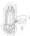
- catch release piston 50 When the pressurized fluid source is connected via inlet 82, catch release piston 50 is locked in the first, rearward hold position, supply trigger 110 is undepressed, and stunner 20 is in a neutral state, as shown in Fig. 1 .
- One or more first radial passageways 85 extend through the body of catch piston 50 from the periphery to catch piston central opening 58, and passageways 84 and 85 are aligned when catch piston 50 is rearward in the hold position.
- pressurized air may flow freely from passageway 84 through passageway 85, through central opening 58 and forward within stunning rod lip 46 to inner chamber 30, behind stunning rod piston 48, and through the open rear end into firing chamber 32 around the inner chamber.
- alignment of the first slot 112a in main valve 114 in the trigger 110 undepressed position allows pressurized air to flow through supply passageway 94 to catch piston cylinder chamber 72 forward of the catch release piston portion 52 and rearward of catch retainer 70, urging catch piston 50 rearward.
- This constant pressure holding catch piston 50 is maintained so long as trigger 110 remains undepressed, which ensures the stunning rod 40 does not fire accidentally in the event the stunner is dropped or otherwise mishandled.
- Catch piston 50 includes in its body a second passageway 89, rearward of the first passageway 85, which in the embodiment shown comprises an open-top slot in the outer wall of catch piston 50 extending around all or a portion of the circumference of the catch piston.
- second passageway 89 is aligned with passageways 90a and 90b, whose ends encircle the catch release piston and are connected, and vent to atmosphere.
- Second passageway 89 is also aligned with passageway 104, and encircles the chamber, and which extends forward from catch release piston chamber 71 to the forward end of inner chamber 30 and in communication with one or more openings 34 alongside and between cushions 25a, 25b.
- Rearward of second passageways 89, third radial passageways 87 extend from central opening 58 to the periphery of the catch piston 50 body.
- Pressurized fluid from the rear of firing chamber 32 exerts a force against stunning rod piston 48, which is held from forward movement only by the position of catch flanges 64 retaining stunning rod rear lip 46.
- an embodiment of the present invention employs main trigger 110, controlling main handle valve 114, in combination with head contact activator 18.
- a head activator chamber passageway 96 extends through the handle and housing from main valve 114 forward to head contact activator 18.
- a passageway 102 extends rearward from head contact activator 18 to the back end of catch piston cylinder chamber 72. Passageway 102 does not intersect with passageway 104.
- the head contact 18 slides fore and aft within nose 23 forward of chamber 98 (see also Fig. 13 ) and is extended by spring (not shown) pressure toward a forward (rightward) position.
- the rear portion or cylindrical projection 118 of the head activator 18 extends partially through the opening in the nose rear wall 27 at the rear of the activator chamber 98, and within the opening of forward cushion 25a.
- a head contact passageway 106 comprises a slot extending around the periphery of the cylindrical body 120 of head contact 18. When trigger 110 is undepressed, head contact slot 106 is not aligned with passageway 96, and a second passage 112b in valve 114 aligns to vent any air in head activator passage 96 to atmosphere through an opening in the handle 28.
- head contact passageway 106 When head contact 18 is in the forward position, head contact passageway 106 is aligned with both passageway 102 and head contact vent 19, and when the catch release piston 50 is in the rearward position, catch piston slot 89 is aligned with both passageway 104 and vent passageway 90b, so that the rearward end of catch piston cylinder chamber 72 vents through the front of housing 22, via vent 19, and the forward end of inner chamber 30 vents through the rear of housing 22, via vent 90b, as shown in Fig. 1 . The stunner will not fire in this position, wherein main trigger 110 and head contact 18 are not depressed.
- a second or auxiliary trigger 116 may be provided to open and close flow though passageway 102, which also must be depressed to open passageway 102 and actuate the stunning rod, as discussed further below. Installation of this optional auxiliary trigger 116 may require passageway 102 to be accessed at a point closer to the tail end 26 of the housing to allow for this added safety feature, with no additional change to the flowpath of passageway 102 as shown in Figs. 1-4 being required.
- the main handle valve 114 is activated by the operator depressing main trigger 110 with one hand against the force of the spring in the valve, and head contact 18 is activated by the operator pressing against the animal's head to move and depress the contact 18 rearward (leftward) in the direction shown by the arrows against the force of the head contact spring, as shown in Fig. 2 , so the rear portion of the head activator 18 moves further into the opening in the rear of the activator chamber 98.
- valve 114 first passageway 112a connects passageway 94 with the handle vent opening and pressurized air from the forward end of catch piston cylinder chamber 72 is exhausted to the atmosphere
- valve 114 second passageway 112b connects passageway 92 to passageway 96 to provide pressurized air from inlet 82 to head contact activator 18. Since head contact 18 is in the rearward position, head contact slot 106 aligns with head activator passageway 96 and permits communication between passageways 96 and 102. Compressed air then flows via passageway 102 to the rearward end of catch piston cylinder chamber 72. If the optional auxiliary trigger 116 is used, it must be depressed to open the valve to permit pressurized air flow through passageway 102.
- catch release piston 50 is moved by the compressed air in the rear of chamber 72 and begins to extend forward (rightward) to its limit, against catch retainer 70. This forward movement of end 51 releases catches 60 and permits inward retraction of forward catch latches 64 to relief portion 56.
- stunning rod lip 46 is urged forward and moves against the catch beveled flange surfaces 65, moving catch forward end flanges inward and releasing stunning rod 40.
- Fig. 2 shows the catch piston in an intermediate position as it is moved forward from the first, hold position toward the second, release position.
- Passageway 85 has moved out of alignment from passageway 84, and passageway 84 is consequently closed to prevent the pressurized fluid from flowing from inlet 82.
- operation of valve 114 by depressing the supply trigger does not permit further pressurized fluid to flow from the source into either the inner stunning rod chamber 30 or firing chamber 32 because of the misalignment of supply passageway 84 and catch piston first passageway 85. Because the catch piston 50 has begun to be moved forward toward its second release position, the second passageway slot 89 is not yet aligned with supply passageway 84.
- FIG. 3 shows the animal stunner 20 with the stunning rod 40 in the full forward, end-of-stroke position.
- piston 48 contacts cushion 25b, and both cushions 25b and 25a at the forward end of stunning rod chamber 30 compress to cause forward motion of piston 48 and rod 40 to decelerate and stop within the stunning rod chamber.
- the stunning rod striking end 44 is now fully extended through head contact opening 17.
- pressurized fluid continues to flow from the source through the supply passageway 84, through the slot 89 extending around the catch piston 50 and into internal passageway 104 and through openings 34 into the forward end of the stunning rod chamber 30 at cushions 25a, 25b ahead of stunning rod piston 48.
- a portion of the pressurized air flows from the front of stunning rod chamber 30 through a passageway comprising one or more small slots 108 between the rear portion or projection 118 of the head contact activator 18 and the opening in nose rear wall 27 at the rear of the activator chamber 98, which pressurized air along with the spring assist moves the head contact 18 fully forward to its deactivated position.
- slots 108 may be formed in or around the opening in nose rear wall 27 ( Fig. 3 )
- the embodiment shown in Figs. 12A and 12B for the head contact 18 shows slots 108 comprising four (4) slots or grooves arrayed around and formed in the periphery of the rear portion or projection 118 of the head contact activator.
- third radial passageways 87 are in alignment with vent passageways 90a, 90b, and permit air behind piston 48 to flow through catch piston central opening 58 and vent to atmosphere out of housing rear portion 26. Pressurized air being supplied from passageway 104 to the forward end of stunning rod chamber 30 acts against stunning rod piston 48 to begin to drive it rearward.
- the pressurized air in chamber 30 forward end retracts the stunning rod 40 rearward (leftward; as shown by the arrow) until lip 46 of stunning rod 40 passes behind the front flanges 64 of catches 60, and stunning rod rear end 41 contacts the forward end 51 of catch piston 50. Because catch piston cylinder chamber 72 is fully vented fore and aft of catch release piston portion 52, as stunning rod piston strikes forward end 51, catch release piston 50 is free to begin to move back from the second, forward position toward the first, hold position.
- the catch piston second passageway 89 moves out of alignment with air supply passageway 84
- third passageway 87 moves out of alignment with vent passageways 90a, 90b
- catch piston first passageway 85 is not yet in alignment with the air supply passageway 82.
- Trigger 110 may be released by the operator, and in its undepressed position as shown in Fig.
- FIG. 14-17 An alternate embodiment of a nose 23' and a head contact activator 18' disposed on a front end 14' of an animal stunner 20' and sized to receive a larger stunning rod 40' having a larger striking end 44' is presented in Figs. 14-17 .
- This particular nose and head contact configuration is for use in the animal stunner 20' embodiment constructed to prevent penetration of (i.e. concuss) an animal's head, as previously described.
- the head contact 18' slides fore and aft within nose 23' forward of chamber 98' and is biased by a spring 130 pressure toward a forward (rightward) position.
- a nose valve 132 is disposed within the nose 23' and is interactive via the sliding motion of the head contact 18'.
- a cylindrical projection 118' of the head contact activator 18' extends partially through the opening in the front end of the nose 23', and is disengaged with the nose valve 132. The stunner will not fire in this position, wherein main trigger 110 and head contact 18' are not depressed.
- the main handle valve 114 is activated by the operator depressing the main trigger 110 with one hand (and optionally auxiliary trigger 116 with the other hand) against the force of the spring in the valve 114, and nose valve 132 is activated by the operator pressing the head contact 18' against the animal's head to move and depress the head contact 18' rearward (leftward) against the force of the springs 130, as shown in Fig. 15 , such that a head contact tab 18a' extending from the rear portion of the head contact 18' engages with the nose valve 132 to activate it and allow for the passage of fluid.
- the larger striking end 44' of the stunning rod 40' used in the stunner 20' has a larger diameter than that of its penetrating counterpart 44 as previously described.
- This striking end 44' is affixed to the end of the rod 40' by a bolt, screw, nail, or other acceptable fastening means.
- the inner diameter of head contact 18' conforms to this striking end 44' diameter to allow for a sliding fit, such that the rod does not rattle or otherwise displace itself during the firing sequence.
- the stunner and its components may be made of steel, aluminum, composite or other suitable materials.
- the stunning rod may be constructed as described in U.S. Patent No. 10,258,051 titled "LIGHTWEIGHT STUNNING ROD".
- the construction of the stunner shown is sufficiently robust so that it will avoid accidental firing if dropped by the operator.
- the present invention therefore provides a pneumatic animal stunner and method of use that has one or more of the following advantages: 1) reduction in the complexity of valve and venting systems; 2) reduced cost to manufacture the stunner; 3) reduction in weight of an automatically retracting stunner; 4) reduced operator fatigue in using the stunner; 5) reduced pressure of the pressurized fluid needed to operate the stunner, which may be below 175 psi (1.3 MPa) and as low as about 125 psi (1 MPa) and rugged construction to avoid accidental firing and damage.
Landscapes
- Life Sciences & Earth Sciences (AREA)
- Engineering & Computer Science (AREA)
- Food Science & Technology (AREA)
- Actuator (AREA)
- Infusion, Injection, And Reservoir Apparatuses (AREA)
- Catching Or Destruction (AREA)
- Fluid-Damping Devices (AREA)
Description
- This invention relates in general to a pneumatic animal stunner used in livestock/slaughterhouse operations. More specifically, this invention relates to a pneumatic animal stunner having a housing with a catch piston chamber, a stunning rod chamber, a supply passageway, a stunning rod slideable within the stunning rod chamber, a catch for holding and releasing the stunning rod, a catch piston disposed adjacent the catch, a first passageway for permitting airflow to a rearward end of the stunning rod chamber, and a second passageway for permitting airflow to a forward end of the stunning rod chamber. The invention further relates to a method of stunning an animal utilizing the pneumatic animal stunner identified above and delineated in claims 1-9.
- In livestock production plants, it is important to stun and disable an animal for processing. In livestock production farms, it is important to euthanize animals suffering from severe injury or irreversible disease so as to prevent the spread of illness. Although numerous methods have been used to stun and euthanize livestock, captive bolt mechanisms have proven to be the most efficient, inexpensive, and humane way to disable the animal. Particularly, pneumatic captive bolt devices have been used in this capacity.
- Pneumatic stunners that provide for automatic retraction of the stunning rod typically have complex valve systems that are more difficult to manufacture and tend to add to the cost of the stunner. Such valve systems also tend to add to weight to the device, which may increase operator fatigue. Additional issues involve the requirement of supplying the pressurized fluid at relatively high pressures, typically in the range of 175 - 220 psi (1.3 - 1.6 MPa). Portable stunners are generally lighter in weight, but after firing often require manual retraction of the stunning rod, also adding to operator fatigue.
- In
EP 3616524 A1 , titled "STUNNER", an animal stunner used in livestock/slaughterhouse operations teaches a piston slideable within an inner chamber, and a fire pressure chamber within an annular configuration disposed adjacent a rearward or central end of the inner chamber. A valve system alternately controls flow of the pressurized fluid from the fire pressure chamber to the rearward end of the inner chamber to move the piston and drive the stunning rod. In contrast, the present invention utililzes reduced pressure of the pressurized fluid needed for operation, and has reduced complexity in valve and venting systems. - Bearing in mind the problems and deficiencies of the prior art, it is therefore an object of the present invention to provide a pneumatic animal stunner and method of use that has reduced complexity in valve and venting systems and reduced cost to manufacture.
- It is another object of the present invention to provide a pneumatic animal stunner that has reduced weight and reduced operator fatigue.
- It is a further object of the present invention to provide a pneumatic animal stunner that may use reduced pressure of the pressurized fluid needed for operation, and has rugged construction to avoid accidental firing and damage.
- Still other objects and advantages of the invention will in part be obvious and will in part be apparent from the specification.
- The above and other objects, which will be apparent to those skilled in the art, are achieved in the present invention which is directed to a pneumatic animal stunner as set out in the appended set of claims 1-9, which includes a housing having a catch piston chamber, a stunning rod chamber, a supply passageway disposed in the housing between a source of pressurized fluid and the catch piston chamber, a catch mounted within the housing for alternately holding and releasing the stunning rod, and a catch piston disposed adjacent the catch and in sliding contact within the catch piston chamber, the catch piston being adapted to move between a first position urging the catch to hold and prevent the stunning rod from being driven forward, and a second position permitting the catch to release and permit the stunning rod to be driven forward. A first passageway in the catch piston permits air to flow from the source of pressurized fluid through the first passageway to a rearward end of the stunning rod chamber. A second passageway in the catch piston permits air to flow from the source of pressurized fluid through the second passageway to a forward end of the stunning rod chamber.
- The present invention is also directed to a method of stunning an animal. The method provides for a pneumatic animal stunner according to claims 1-9.The method includes the steps according to claims 10-13, including: moving the catch piston into the first position urging the catch to hold and prevent the stunning rod from being driven forward, moving the catch piston towards the second position to release the catch, causing pressurized fluid to flow from the source through the first passageway into the rearward end of the stunning rod chamber to drive the stunning rod forward upon release of the catch to stun the animal, and, upon movement of the catch piston into the second position, flowing pressurized fluid from the source through the second passageway into the forward end of the stunning rod chamber to drive the stunning rod rearward.
- The invention also relates to a catch piston according to
claim 14 for use in opening and closing catches in such a pneumatic animal stunner. - In an embodiment not part of the claimed invention, the method further provides a resilient annular cushion disposed at a front end of the stunning rod chamber, and an internal passageway . The method further includes the step of causing pressurized fluid to flow through the internal passageway into the forward end of the stunning rod chamber between the pair of resilient annular cushions to drive the stunning rod rearward.
- The features of the invention believed to be novel and the elements characteristic of the invention are set forth with particularity in the appended claims. The figures are for illustration purposes only and are not drawn to scale. Some figures relate to embodiments that are not according to the invention, and are present for illustration purposes only. The invention itself, however, both as to organization and method of operation, may best be understood by reference to the detailed description which follows taken in conjunction with the accompanying drawings in which:
-
Fig. 1 is a cross-sectional view of an embodiment of the stunner of the present invention with the triggers undepressed, catches, catch piston and stunning rod in the first, neutral hold position as they would be initially before firing, and also after firing when the stunning rod is fully retracted and captured by the catches. -
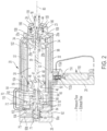
Fig. 2 is a cross-sectional view of the stunner ofFig. 1 after firing showing the trigger depressed and the head contact activated, shortly after the catches have released the stunning rod to move forward and the catch piston is in an intermediate position, moving forward, between the first hold position and the second forward position. -
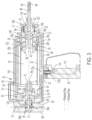
Fig. 3 is a cross-sectional view of the stunner ofFig. 1 after theFig. 2 firing showing the trigger depressed and the head contact deactivated and the stunning rod in the fully forward, end-of-stroke position. -
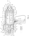
Fig. 4 is a cross-sectional view of the stunner ofFig. 1 after theFig. 3 end-of-stroke position, showing the trigger depressed and the head contact deactivated and the stunning rod returning rearward and in contact with the front of the catch piston and the catch piston is in an intermediate position, moving rearward, between the second forward position and the first hold position. -
Fig. 5A is a rear perspective view of the stunner ofFig. 1 . -
Fig. 5B is a front perspective view of the stunner ofFig. 1 . -
Fig. 5C is a side elevational view of the stunner ofFig. 1 . -
Fig. 6 is a cross-sectional view of the catch cylinder of the stunner ofFig. 1 . -
Fig. 7A is a front perspective view of the catch release piston of the stunner ofFig. 1 . -
Fig. 7B is a front view of the catch release piston of the stunner ofFig. 1 . -
Figs. 7C is a cross-sectional view of the catch release piston of the stunner ofFig. 1 . -
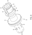
Fig. 8 is a perspective view of the catch release piston and catches of the stunner ofFig. 1 . -
Fig. 9A is a side elevational view of the catch release piston and catches of the stunner ofFig. 1 . -
Fig. 9B is a rear view of the catch release piston of the stunner ofFig. 1 . -
Fig. 9C is a front view of the catch release piston and catches of the stunner ofFig. 1 . -
Fig. 10A is a side view of the catches of the stunner ofFig. 1 . -
Fig. 10B is a rear view of the catches of the stunner ofFig. 1 . -
Fig. 10C is a front view of the catches of the stunner ofFig. 1 . -
Fig. 10 is a perspective view of the catches of the stunner ofFig. 1 . -
Fig. 11A is a side view of a single one of the catches of the stunner ofFig. 1 . -
Fig. 11B is an inside perspective view of a single one of the catches of the stunner ofFig. 1 . -
Fig. 11C is an outside perspective view of a single one of the catches of the stunner ofFig. 1 . -
Fig. 12A is a front perspective view of the head contact activator of the stunner ofFig. 1 . -
Fig. 12B is a rear perspective view of the head contact activator of the stunner ofFig. 1 . -
Fig. 13 is a cross-sectional view of the housing nose of the stunner ofFig. 1 . -
Fig. 14 is a side cross-sectional view of an embodiment of the stunner rod, liner, nose, and head contact configuration with the rod in the fully retracted position. -
Fig. 15 is a side cross-sectional view of the animal stunner configuration ofFig. 14 with the rod in the fully extended position. -
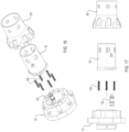
Fig. 16 is a perspective exploded view of the nose and head contact configuration of the stunner embodiment ofFig. 14 . -
Fig. 17 is a side exploded view of the nose and head contact configuration of the stunner embodiment ofFig. 14 . - In describing the embodiment(s) of the present invention, reference will be made herein to
Figs. 1-17 of the drawings in which like numerals refer to like features of the invention. - Structure and operation of the
exemplary animal stunner 20 is shown in general in the cross-sections ofFigs. 1-4 and the perspective and side views ofFigs. 5A-5C , and in the components shown inFigs. 6-13 . Thestunner 20 includes an outer elongatedhollow housing 22, ahead contact activator 18 moveable within anouter housing nose 23, afront end 24, atail end 26, astunning rod 40 moveable forward and rearward aboutlongitudinal axis 80 and catches 60 arrayed aboutlongitudinal axis 80 for holding and releasing thestunning rod 40. The stunner is grasped by amain handle 28 extending belowbody 22 and arear handle 29 extending fromtail end 26. The forward and rearward directions described herein are with respect to the stunnerfront end 24, and inward and outward directions described herein are with respect toaxis 80.Housing 22 includes within it a generally cylindrical inner pressure orstunning rod chamber 30 for the stunning rod and piston and asurrounding firing chamber 32 to receive and hold a pressurized fluid. - A circular
stunning rod piston 48 surrounded by an O-ring seal 49 slides along the inner cylindrical surface ofinner chamber 30 withinhousing 22.Piston 48 moves forward and rearward alongaxis 80, and carriesstunning rod 40. In the embodiment shown the stunning rod and piston are formed integrally of one piece, but they may be separate components secured together. Anannular firing chamber 32 surroundsinner chamber 30 withinhousing 22 and is open at the rear, so that air can move freely and quickly from firingchamber 32 to the region ofinner chamber 30 behindpiston 48 upon firing of the stunner, as explained further below. Noserear wall 27 at front ofchamber 30 limits forward motion ofpiston 48 andstunning rod 40, and carries a pair of resilientannular cushions rearward end 41 ofstunning rod 40 has an opening with aninward lip 46 extending about its periphery, which lip is alternately held and released by an outwardly extendingflange 64 at the forward end ofcatch 60. The body or shaft ofstunning rod 40 may be circular or non-circular in shape as viewed in cross-section normal to the longitudinal axis. The forward orstriking end 44 of the stunning rod extends in a sliding fit through a correspondingly configuredopening 17 inhead contact activator 18 at the front ofhousing 22 to be driven toward the animal's head when the catch releases thestunning rod lip 46. The stunning rodforward end 44 is sized with a diameter and configuration either to penetrate, or prevent penetration of (i.e. concuss), the animal's head. The example shown inFigs. 1-5C is of a penetrating rod. - The catch system for holding and releasing the stunning rod as shown in the embodiment is disposed rearward of
stunning rod chamber 30 in the rear ofhousing 22.Catches 60 are further shown inFigs. 8-11C and in the embodiment shown are three (3) arcuate catches arrayed aroundaxis 80. Each catch may have a body curved in an arc segment about the longitudinal axis, with outwardly extendingflanges catch 60 in the embodiment shown has an arc of more than 90° and less than 120° so that three catches may be arranged cylindrically about thelongitudinal axis 80 with sufficient space between adjacent catches to pivot inwardly without interfering with one another. Fewer or more than three catches may be employed. A generally hollowcylindrical catch retainer 70 extends forward from the rear end ofhousing 22. The front portion ofcatch retainer 70 extends over and around, and secures the rearward end portions ofcatches 60. Thecatch retainer 70 has at its forward end an inwardly facing groove, which receives the catchrear end flanges 66 extending on a side away fromaxis 80. Catch release piston 50 (see alsoFigs. 7A-7C ) slides within a central opening in catch cylinder 75 (see alsoFig. 6 ) disposed onstunner tail end 26 and a front portion is slidingly received within the central opening ofretainer 70 and moves forward and rearward alongaxis 80, as shown in cross-section inFigs. 1-4 .Catch piston 50 has circularrelease piston portion 52 sliding within a cylindricalcatch piston chamber 72 behind the rear portion ofcatch retainer 70.Catch release piston 50 has acentral opening 58 extending alongaxis 80 toforward end 51, and forward ofrelease piston portion 52catch release piston 50 has a generally cylindrical body portion within and contacting the rearward ends of catches 60 (see alsoFigs. 8 and9A-9C ). The support provided to the catch rear end portions by the inner catch piston body and the outer catch retainer permits thecatches 60 to rotate and theirforward end flanges 64 to pivot inwardly and outwardly aroundrearward end flanges 66 in theretainer 70 groove. - The catch forward ends are moved outwardly to a hold position, away from
axis 80, so thatforward end flanges 64 contact therod 40 rear end portion and prevent the stunning rod from being driven forward. To accomplish such movement,catch piston 50 has aforward end portion 51 within the catches which has a diameter sufficient to contact and urge catch forwardend portion flanges 64 outward into engagement with the stunningrod opening lip 46. Whencatch piston 50 is moved rearward into the hold position, the catchforward end portion 64 is aligned with and in contact with both the stunningrod opening lip 46 and the catch pistonforward end portion 51. - Rearward of the
forward end portion 51 the catch piston has arelief portion 56 with a diameter smaller than the forward end portion diameter. This relief portion diameter is sufficiently small to permit catchforward end portion 64 to move freely inward to the release position, withflanges 64 out of engagement with the stunningrod opening lip 46. Whencatch piston 50 is moved forward from the first, hold position to the second, release position, catch front ends 51 are no longer in a position to prevent catchfront end 64 from moving inward. The rearward sides offront flanges 64 are beveled 65 at an angle greater than 90° with the catch body 62 (see alsoFigs. 10A-10D and11A-11C ), so that aspiston 48 andstunning rod 40 move forward pressure fromstunning rod lip 46 will causeflanges 64 to spring inward intorelief portion 56 as the stunning rod lip moves along the beveled flange surfaces 65. When the catchforward end flanges 64 are disengaged fromrod lip 46, thestunning rod 40 is fully released and driven forward. -
Stunner 20 is operable by pressurized fluid, such as compressed air or any other suitable fluid. For the example shown, compressed air is the fluid and is supplied from a hose or line connected to an air compressor. Air pressure and flow may be controlled by a regulator (not shown) and the compressed air flows through intoinlet 82 inhousing 22, rearward ofmain handle 28. - Flow of the pressurized air is then split after
inlet 82, betweeninternal passageway 84 andtrigger supply passageway 92.Internal passageway 84 communicates withcatch release piston 50, and the terminus of the passageway may encircle the piston, and triggersupply passageway 92 communicates withmain valve 114 operated bytrigger 110 inhandle 28. A spring (not shown) invalve 114 urges the valve into a first, downward position, and urges the trigger to the undepressed position. Whentrigger 110 is in the undepressed position, afirst passage 112a inmain valve 114 permits air to flow fromtrigger supply passageway 92 to supplypassageway 94, in communication with catchpiston cylinder chamber 72. - When the pressurized fluid source is connected via
inlet 82,catch release piston 50 is locked in the first, rearward hold position,supply trigger 110 is undepressed, andstunner 20 is in a neutral state, as shown inFig. 1 . Air flows up throughpassageway 84, the terminus of which encircleschamber 71 adjacent a rear portion ofcatch piston 50. One or more first radial passageways 85 extend through the body ofcatch piston 50 from the periphery to catch pistoncentral opening 58, andpassageways 84 and 85 are aligned whencatch piston 50 is rearward in the hold position. Because there are spaces between theindividual catches 60, pressurized air may flow freely frompassageway 84 through passageway 85, throughcentral opening 58 and forward withinstunning rod lip 46 toinner chamber 30, behindstunning rod piston 48, and through the open rear end into firingchamber 32 around the inner chamber. To maintaincatch release piston 50 in the hold position, alignment of thefirst slot 112a inmain valve 114 in thetrigger 110 undepressed position allows pressurized air to flow throughsupply passageway 94 to catchpiston cylinder chamber 72 forward of the catchrelease piston portion 52 and rearward ofcatch retainer 70, urgingcatch piston 50 rearward. This constant pressure holdingcatch piston 50 is maintained so long astrigger 110 remains undepressed, which ensures thestunning rod 40 does not fire accidentally in the event the stunner is dropped or otherwise mishandled. -
Catch piston 50 includes in its body asecond passageway 89, rearward of the first passageway 85, which in the embodiment shown comprises an open-top slot in the outer wall ofcatch piston 50 extending around all or a portion of the circumference of the catch piston. In the hold position ofFig. 1 ,second passageway 89 is aligned withpassageways Second passageway 89 is also aligned withpassageway 104, and encircles the chamber, and which extends forward from catchrelease piston chamber 71 to the forward end ofinner chamber 30 and in communication with one ormore openings 34 alongside and betweencushions second passageways 89, thirdradial passageways 87 extend fromcentral opening 58 to the periphery of thecatch piston 50 body. - Pressurized fluid from the rear of firing
chamber 32 exerts a force againststunning rod piston 48, which is held from forward movement only by the position ofcatch flanges 64 retaining stunning rodrear lip 46. - To actuate the firing of
stunning rod 40, an embodiment of the present invention employsmain trigger 110, controllingmain handle valve 114, in combination withhead contact activator 18. In the embodiment shown, a headactivator chamber passageway 96 extends through the handle and housing frommain valve 114 forward tohead contact activator 18. Apassageway 102 extends rearward fromhead contact activator 18 to the back end of catchpiston cylinder chamber 72.Passageway 102 does not intersect withpassageway 104. - The
head contact 18 slides fore and aft withinnose 23 forward of chamber 98 (see alsoFig. 13 ) and is extended by spring (not shown) pressure toward a forward (rightward) position. In the forward, deactivated position, the rear portion orcylindrical projection 118 of thehead activator 18 extends partially through the opening in the noserear wall 27 at the rear of theactivator chamber 98, and within the opening offorward cushion 25a. Ahead contact passageway 106 comprises a slot extending around the periphery of thecylindrical body 120 ofhead contact 18. Whentrigger 110 is undepressed,head contact slot 106 is not aligned withpassageway 96, and asecond passage 112b invalve 114 aligns to vent any air inhead activator passage 96 to atmosphere through an opening in thehandle 28. Whenhead contact 18 is in the forward position,head contact passageway 106 is aligned with bothpassageway 102 andhead contact vent 19, and when thecatch release piston 50 is in the rearward position,catch piston slot 89 is aligned with bothpassageway 104 and ventpassageway 90b, so that the rearward end of catchpiston cylinder chamber 72 vents through the front ofhousing 22, viavent 19, and the forward end ofinner chamber 30 vents through the rear ofhousing 22, viavent 90b, as shown inFig. 1 . The stunner will not fire in this position, whereinmain trigger 110 andhead contact 18 are not depressed. Optionally, a second orauxiliary trigger 116 may be provided to open and close flow thoughpassageway 102, which also must be depressed to openpassageway 102 and actuate the stunning rod, as discussed further below. Installation of this optionalauxiliary trigger 116 may requirepassageway 102 to be accessed at a point closer to thetail end 26 of the housing to allow for this added safety feature, with no additional change to the flowpath ofpassageway 102 as shown inFigs. 1-4 being required. - To commence the firing sequence, the
main handle valve 114 is activated by the operator depressingmain trigger 110 with one hand against the force of the spring in the valve, andhead contact 18 is activated by the operator pressing against the animal's head to move and depress thecontact 18 rearward (leftward) in the direction shown by the arrows against the force of the head contact spring, as shown inFig. 2 , so the rear portion of thehead activator 18 moves further into the opening in the rear of theactivator chamber 98. As themain handle valve 114 moves into the second, upward position,valve 114first passageway 112a connectspassageway 94 with the handle vent opening and pressurized air from the forward end of catchpiston cylinder chamber 72 is exhausted to the atmosphere, andvalve 114second passageway 112b connectspassageway 92 topassageway 96 to provide pressurized air frominlet 82 tohead contact activator 18. Sincehead contact 18 is in the rearward position,head contact slot 106 aligns withhead activator passageway 96 and permits communication betweenpassageways passageway 102 to the rearward end of catchpiston cylinder chamber 72. If the optionalauxiliary trigger 116 is used, it must be depressed to open the valve to permit pressurized air flow throughpassageway 102. As a result ofmain trigger 110 andhead contact 18 being depressed, and optionallyauxiliary trigger 116,catch release piston 50 is moved by the compressed air in the rear ofchamber 72 and begins to extend forward (rightward) to its limit, againstcatch retainer 70. This forward movement ofend 51 releases catches 60 and permits inward retraction of forward catch latches 64 torelief portion 56. A result of the pressurized air behindstunning rod piston 48,stunning rod lip 46 is urged forward and moves against the catch beveled flange surfaces 65, moving catch forward end flanges inward and releasingstunning rod 40. - The pressure of air from
inlet 82 that had flowed through catch piston central opening 58 (Fig. 1 ) is assisted by pressurized charge air flowing from firingchamber 32 against the rear ofpiston 48. As a result, asstunning rod 40 is released from the catches it moves forward (rightward) at a high rate of speed, with the stunning rod forward orstriking end 44 moving through thehead contact opening 17 in the direction of the arrow as shown inFig. 2 . The remaining air ininner chamber 30 forward of thestunning rod piston 48, which previously had been vented (Fig. 1 ) begins to be compressed. -
Fig. 2 shows the catch piston in an intermediate position as it is moved forward from the first, hold position toward the second, release position. Passageway 85 has moved out of alignment frompassageway 84, andpassageway 84 is consequently closed to prevent the pressurized fluid from flowing frominlet 82. When the catch piston is moved forward toward the release position, operation ofvalve 114 by depressing the supply trigger does not permit further pressurized fluid to flow from the source into either the innerstunning rod chamber 30 or firingchamber 32 because of the misalignment ofsupply passageway 84 and catch piston first passageway 85. Because thecatch piston 50 has begun to be moved forward toward its second release position, thesecond passageway slot 89 is not yet aligned withsupply passageway 84. -
Fig. 3 shows theanimal stunner 20 with thestunning rod 40 in the full forward, end-of-stroke position. At the end of the forward stroke ofstunning rod 40,piston 48contacts cushion 25b, and bothcushions stunning rod chamber 30 compress to cause forward motion ofpiston 48 androd 40 to decelerate and stop within the stunning rod chamber. The stunning rodstriking end 44 is now fully extended throughhead contact opening 17. - Since the
catch piston 50 is still in the second, forward position, pressurized fluid continues to flow from the source through thesupply passageway 84, through theslot 89 extending around thecatch piston 50 and intointernal passageway 104 and throughopenings 34 into the forward end of thestunning rod chamber 30 atcushions stunning rod piston 48. A portion of the pressurized air flows from the front ofstunning rod chamber 30 through a passageway comprising one or moresmall slots 108 between the rear portion orprojection 118 of thehead contact activator 18 and the opening in noserear wall 27 at the rear of theactivator chamber 98, which pressurized air along with the spring assist moves thehead contact 18 fully forward to its deactivated position. While one or more of theseslots 108 may be formed in or around the opening in nose rear wall 27 (Fig. 3 ), the embodiment shown inFigs. 12A and 12B for thehead contact 18shows slots 108 comprising four (4) slots or grooves arrayed around and formed in the periphery of the rear portion orprojection 118 of the head contact activator. With thehead contact 18 in the forward, deactivated position, further flow of pressurized air frommain valve 114 throughpassageway 96 is blocked, andhead contact passageway 106 connectspassageway 102 to thehead contact vent 19 to exhaust air pressure from catchpiston cylinder chamber 72 to the atmosphere, so thatcatch piston 50 is no longer urged forward. This air flow throughpassageway 108 to pushhead contact 18 forward acts as a safety feature, so that the stunner can not be repeatedly fired by continuing to press the trigger. - With the
catch release piston 50 remaining in the second, forward position, thirdradial passageways 87 are in alignment withvent passageways piston 48 to flow through catch pistoncentral opening 58 and vent to atmosphere out of housingrear portion 26. Pressurized air being supplied frompassageway 104 to the forward end ofstunning rod chamber 30 acts againststunning rod piston 48 to begin to drive it rearward. - As shown in
Fig. 4 , the pressurized air inchamber 30 forward end retracts thestunning rod 40 rearward (leftward; as shown by the arrow) untillip 46 ofstunning rod 40 passes behind thefront flanges 64 ofcatches 60, and stunning rodrear end 41 contacts theforward end 51 ofcatch piston 50. Because catchpiston cylinder chamber 72 is fully vented fore and aft of catchrelease piston portion 52, as stunning rod piston strikesforward end 51,catch release piston 50 is free to begin to move back from the second, forward position toward the first, hold position. In an intermediate position between the second and first positions, the catch pistonsecond passageway 89 moves out of alignment withair supply passageway 84,third passageway 87 moves out of alignment withvent passageways air supply passageway 82. As a result, in this intermediate position no additional pressurized air is supplied intostunning rod chamber 30 forward of thestunning rod piston 48, and thestunning rod piston 48 is driven back by the remaining air pressure. - However, as a result of momentum of
piston 48 striking it,catch piston 50 is retracted rearward (leftward) into thecatch cylinder 75 fully into its first, hold position. This rearward movement closes thecatches 60 by the force of catch piston forward end 51 sliding within the catch forward end portions and urging them outward to cause catchforward end flanges 64 to engage and capturestunning rod lip 46, so that thestunning rod 40 is retained by the catches, as shown inFig. 1 . and the stunner is automatically reset.Trigger 110 may be released by the operator, and in its undepressed position as shown inFig. 1 , withcatch piston 50 is the first, neutral, hold position, the stunner is again pressurized via air throughsupply inlet 82 and the initial, downward position ofvalve 114 as described above, so that pressurized air flows viapassageway 94 to urgecatch piston portion 52 rearward and preventcatch piston 50 andstunning rod 40 from forward motion, so that the stunner is ready for operation again. - An alternate embodiment of a
nose 23' and a head contact activator 18' disposed on a front end 14' of an animal stunner 20' and sized to receive a larger stunning rod 40' having a larger striking end 44' is presented inFigs. 14-17 . This particular nose and head contact configuration is for use in the animal stunner 20' embodiment constructed to prevent penetration of (i.e. concuss) an animal's head, as previously described. - The head contact 18' slides fore and aft within
nose 23' forward of chamber 98' and is biased by aspring 130 pressure toward a forward (rightward) position. Anose valve 132 is disposed within thenose 23' and is interactive via the sliding motion of the head contact 18'. In the forward, deactivated position, a cylindrical projection 118' of the head contact activator 18' extends partially through the opening in the front end of thenose 23', and is disengaged with thenose valve 132. The stunner will not fire in this position, whereinmain trigger 110 and head contact 18' are not depressed. - To commence the firing sequence, the
main handle valve 114 is activated by the operator depressing themain trigger 110 with one hand (and optionallyauxiliary trigger 116 with the other hand) against the force of the spring in thevalve 114, andnose valve 132 is activated by the operator pressing the head contact 18' against the animal's head to move and depress the head contact 18' rearward (leftward) against the force of thesprings 130, as shown inFig. 15 , such that ahead contact tab 18a' extending from the rear portion of the head contact 18' engages with thenose valve 132 to activate it and allow for the passage of fluid. - The larger striking end 44' of the stunning rod 40' used in the stunner 20' has a larger diameter than that of its penetrating
counterpart 44 as previously described. This striking end 44' is affixed to the end of the rod 40' by a bolt, screw, nail, or other acceptable fastening means. The inner diameter of head contact 18' conforms to this striking end 44' diameter to allow for a sliding fit, such that the rod does not rattle or otherwise displace itself during the firing sequence. - The remainder of the firing sequence and construction of the stunner 20' is similar to that as described above for the penetrating
stunner 20, and other salient features of the concussion stunner 20' may alternately be constructed as described inU.S. Patent No. 10,375,969 - The stunner and its components may be made of steel, aluminum, composite or other suitable materials. For example, the stunning rod may be constructed as described in
U.S. Patent No. 10,258,051 - The present invention therefore provides a pneumatic animal stunner and method of use that has one or more of the following advantages: 1) reduction in the complexity of valve and venting systems; 2) reduced cost to manufacture the stunner; 3) reduction in weight of an automatically retracting stunner; 4) reduced operator fatigue in using the stunner; 5) reduced pressure of the pressurized fluid needed to operate the stunner, which may be below 175 psi (1.3 MPa) and as low as about 125 psi (1 MPa) and rugged construction to avoid accidental firing and damage.
- While the present invention has been particularly described, in conjunction with a specific preferred embodiment, it is evident that many alternatives, modifications and variations will be apparent to those skilled in the art in light of the appended claims and the foregoing description. It is therefore contemplated that the description and claims herein will embrace any such alternatives, modifications and variations as falling within the true scope of the present invention.
Claims (15)
- A pneumatic animal stunner (20) comprising:a housing (22) having a catch piston chamber (72), a stunning rod chamber (30) and a front end (24) forward of the stunning rod chamber,a supply passageway (92) in the housing (22) between a source of pressurized fluid and the catch piston chamber;a stunning rod (40) slideable within the stunning rod chamber (30) capable of being driven forward along a longitudinal axis (80) towards and out of the front end (24) of the housing;a catch (60) mounted within the housing for alternately holding and releasing the stunning rod;a catch piston (50) disposed adjacent the catch and in sliding contact within the catch piston chamber, the catch piston being adapted to move between a first position urging the catch to hold and prevent the stunning rod from being driven forward, and a second position permitting the catch to release and permit the stunning rod to be driven forward;a first passageway (85) in the catch piston in alignment with the housing supply passageway when the catch piston is in the first position permitting air to flow from the source of pressurized fluid through the first passageway to a rearward end of the stunning rod chamber; anda second passageway (89) in the catch piston in alignment with the supply passageway when the catch piston is in the second position permitting air to flow from the source of pressurized fluid through the second passageway to a forward end of the stunning rod chamber;wherein when the catch piston is in the first position, pressurized fluid may flow from the source through the supply passageway and the first passageway into the rearward end of the stunning rod chamber to drive the stunning rod forward upon release of the catch, and when the catch piston is in the second position after releasing the catch, pressurized fluid may flow from the source through the supply passageway and the second passageway into the forward end of the stunning rod chamber to drive the stunning rod rearward.
- The pneumatic animal stunner of claim 1 wherein, when the catch piston (50) is in the second position after releasing the catch (60), pressurized fluid may flow from the source through the supply passageway (92) and the second passageway (89) into the forward end of the stunning rod chamber to drive the stunning rod (40) rearward and cause the catch piston (50) to move again to the first position urging the catch to hold and prevent the stunning rod from being driven forward and, more particularly, a stunning rod piston (48) connected to the stunning rod and slideable within the stunning rod chamber and a pair of cushions (25a,b) at a front end of the stunning rod chamber to cushion stopping of the stunning rod and stunning rod piston when the stunning rod piston reaches the front of the stunning rod chamber, and/or an internal passageway in the housing extending from the catch piston chamber to the front of the stunning rod chamber between the pair of cushions and wherein, when the catch piston is in the second position, pressurized fluid may flow from the source through the second passageway in the catch piston and the internal passageway into the forward end of the stunning rod chamber between the pair of cushions to drive the stunning rod rearward.
- The pneumatic animal stunner of claim 1 further including an on/off main valve (114) in the housing to control flow of pressurized fluid from the source to the supply passageway.
- The pneumatic animal stunner of claim 1 wherein the catch piston includes a central passageway, and wherein the first passageway (85) extends from the central passageway to the supply passageway (92) when the catch piston is in the first position to supply pressurized fluid through the central passageway to the rearward end of the stunning rod chamber, and, more particularly, a third passageway (87) in the catch piston permitting air to flow from the rearward end of the stunning rod chamber through the catch piston central passageway and to the atmosphere while the stunning rod is being driven rearward.
- The pneumatic animal stunner of claim 1 wherein the catch piston second passageway (89) comprises a slot in an outer wall of the catch piston in alignment with the supply passageway when the catch piston (50) is in the second position permitting pressurized fluid to flow from the source through the supply passageway and the slot to a forward end of the stunning rod chamber, or, an internal passageway (84) in the housing extending from the catch piston chamber to the front of the stunning rod chamber and wherein the catch piston second passageway comprises a slot in an outer wall of the catch piston in alignment with the supply passageway and the internal passageway when the catch piston is in the second position to permit pressurized fluid to flow from the source through the supply passageway, the slot in the catch piston and the internal passageway into the forward end of the stunning rod chamber to drive the stunning rod rearward.
- The pneumatic animal stunner of claim 1 further including a head contact (18) at the housing front end movable between a deactivated position and a position contacting the animal, the head contact in the position contacting the animal permitting air to flow from the supply passageway to urge the catch piston from the first position to the second position.
- The pneumatic animal stunner of claim 1, comprising:a stunning rod piston (48) connected to the stunning rod (40) and slideable within the stunning rod chamber;at least one resilient cushion (25) disposed at a front of the stunning rod chamber to cushion stopping of the stunning rod and stunning rod piston when the stunning rod piston reaches the front of the stunning rod chamber; andan internal passageway (84) in the housing to supply pressurized fluid from a source of pressurized fluid to the front of the stunning rod chamber alongside the at least one resilient cushion, wherein, pressurized fluid may flow from the source alternately through the supply passageway into the rearward end of the stunning rod chamber to drive the stunning rod forward, and through the internal passageway into the forward end of the stunning rod chamber alongside the at least one resilient cushion to drive the stunning rod rearward.
- The pneumatic animal stunner of claim 7 including a pair of resilient annular cushions (25a,b) disposed at a front of the stunning rod chamber, and wherein the internal passageway has an opening at the front of the stunning rod chamber between the resilient annular cushions.
- The pneumatic animal stunner of claim 1, comprising:a stunning rod piston connected to the stunning rod and slideable within the stunning rod chamber;a head contact (18) at the housing front end having a rear portion extending through an opening in a front end of the stunning rod chamber, the head contact being movable between a deactivated position and a position contacting the animal, the head contact in the deactivated position blocking flow of pressurized fluid from the source to the rearward end of the stunning rod chamber, the head contact in the position contacting the animal permitting air to flow from the supply passageway to urge the catch piston from the first position to the second position;an internal passageway (84) in the housing to supply pressurized fluid from a source of pressurized fluid to the front of the stunning rod chamber; anda passageway between the head contact rear portion and the opening in the front end of the stunning rod chamber, wherein, when the head contact is in the position contacting the animal pressurized fluid may flow from the source through the supply passageway into the rearward end of the stunning rod chamber to drive the stunning rod forward, and when the pressurized fluid flows through the internal passageway into the forward end of the stunning rod chamber to drive the stunning rod rearward, a portion of the pressurized fluid flows through the passageway between the head contact rear portion and the opening in the front end of the stunning rod chamber to move the head contact into the deactivated position blocking flow of pressurized fluid from the source to the rearward end of the stunning rod chamber, and, more particularly, wherein the head contact includes a rear projection extending through the opening in a front end of the stunning rod chamber and the passageway between the head contact rear portion and the opening in the front end of the stunning rod chamber comprises a plurality of slots formed in a periphery of the head contact rear projection, and/or, at least one resilient cushion disposed at a front end of the stunning rod chamber to cushion stop the stunning rod and stunning rod piston when the stunning rod piston reaches the front of the stunning rod chamber; andan internal passageway in the housing to supply pressurized fluid from a source of pressurized fluid to the front of the stunning rod chamber alongside the at least one resilient cushion, wherein, pressurized fluid may flow from the source alternately through the supply passageway into the rearward end of the stunning rod chamber to drive the stunning 15 rod forward, and through the internal passageway into the forward end of the stunning rod chamber alongside the at least one resilient cushion to drive the stunning rod rearward.
- A method of stunning an animal comprising:providing a pneumatic animal stunner (20) according to at least one of the preceding claims;moving the catch piston (50) of said pneumatic animal stunner into the first position urging the catch to hold and prevent the stunning rod (40) from being driven forward;moving the catch piston (50) toward the second position to release the catch (60);causing pressurized fluid to flow from the source through the first passageway (85) into the rearward end of the stunning rod chamber to drive the stunning rod forward upon release of the catch to stun the animal, andupon movement of the catch piston (50) into the second position, pressurized fluid flows from the source through the second passageway (89) into the forward end of the stunning rod chamber to drive the stunning rod rearward.
- The method of claim 10 wherein the catch piston (50) is held in the first position by a buildup of pressurized fluid within the catch piston chamber forward of a catch release piston portion and rearward of a catch retainer, the pressurized fluid being supplied from the supply passageway.
- The method of claim 10, comprising:providing a stunning rod piston connected to the stunning rod and slideable within the stunning rod chamber;providing at least one resilient cushion disposed at a front of the stunning rod chamber to cushion stopping of the stunning rod and stunning rod piston when the stunning rod piston reaches the front of the stunning rod chamber;providing an internal passageway in the housing to supply pressurized fluid from a source of pressurized fluid to the front of the stunning rod chamber alongside the at least one resilient cushion; andcausing pressurized fluid to flow from the source alternately through the supply passageway into the rearward end of the stunning rod chamber to drive the stunning rod forward, and through the internal passageway into the forward end of the stunning rod chamber alongside the at least one resilient cushion to drive the stunning rod rearward, and, more particularly,providing a pair of resilient annular cushions disposed at a front end of the stunning rod chamber, and wherein the internal passageway has an opening at the front of in the stunning rod chamber between the resilient annular cushions, and causing pressurized fluid to flow through the internal passageway into the forward nd of the stunning rod chamber between the pair of resilient annular cushions to drive the stunning rod rearward.
- The method of claim 10, further comprising:providing a stunning rod piston (48) connected to the stunning rod (40) and slideable within the stunning rod chamber;providing a head contact (18) at the housing front end having a rear portion extending through an opening in a front end of the stunning rod chamber, the head contact being movable between a deactivated position and a position contacting the animal, the head contact in the deactivated position blocking flow of pressurized fluid from the source to the rearward end of the stunning rod chamber, the head contact in the position contacting the animal permitting air to flow from the supply passageway to urge the catch piston from the first position to the second position;an internal passageway (84) in the housing to supply pressurized fluid from a source of pressurized fluid to the front of the stunning rod chamber;a passageway between the head contact rear portion and the opening in the front end of the stunning rod chamber;contacting the animal with the head contact to permit pressurized fluid to flow from the source through the supply passageway into the rearward end of the stunning rod chamber to drive the stunning rod forward; andcausing the pressurized fluid to flow through the internal passageway into the forward end of the stunning rod chamber to drive the stunning rod rearward, whereupon a portion of the pressurized fluid flows through the passageway between the head contact rear portion and the opening in the front end of the stunning rod chamber to move the head contact into the deactivated position blocking flow of pressurized fluid from the source to the rearward end of the stunning rod chamber.
- A catch piston (50) for use in opening and closing catches (60) in a pneumatic animal stunner (20) according to any one of claims 1 to 9, the catches (60) alternately holding and releasing a stunning rod (40) to drive from a neutral position forward to stun the animal, said catch piston comprising:a catch piston body adapted to be positioned adjacent the catches and slideable within a catch piston chamber (72), the catch piston (50) having a length and being adapted to move between a first position urging the catches to hold the stunning rod (40), and a second position permitting the catches to release the stunning rod;a central passageway extending longitudinally through the length of the body;a first passageway (85) in the catch piston body positioned to align with a housing supply passageway when the catch piston is in the first position permitting air to flow from a source of pressurized air through the first passageway and through the central passageway to a rearward end of the stunning rod;a second passageway (89) in the catch piston body positioned to align with the supply passageway (84) when the catch piston is in the second position permitting air to flow from the source of pressurized fluid through the second passageway to a forward portion of the stunning rod; anda third passageway (87) in the catch piston body permitting air to flow from the rearward end of the stunning rod through the catch piston central passageway and to the atmosphere while the stunning rod is being returned to the neutral position.
- The catch piston of claim 14 wherein the second passageway comprises a slot in an outer wall of the catch piston in alignment with the supply passageway when the catch piston is in the second position permitting pressurized fluid to flow from the source through the supply passageway and the slot to a forward end of the stunning rod chamber.
Priority Applications (1)
| Application Number | Priority Date | Filing Date | Title |
|---|---|---|---|
| EP23172247.1A EP4226769A1 (en) | 2020-04-15 | 2020-12-29 | Low pressure stunner, stunning method and venting system |
Applications Claiming Priority (3)
| Application Number | Priority Date | Filing Date | Title |
|---|---|---|---|
| US202063010314P | 2020-04-15 | 2020-04-15 | |
| US17/123,748 US11278031B2 (en) | 2020-04-15 | 2020-12-16 | Low pressure stunner |
| PCT/US2020/067258 WO2021211176A1 (en) | 2020-04-15 | 2020-12-29 | Low pressure stunner |
Related Child Applications (2)
| Application Number | Title | Priority Date | Filing Date |
|---|---|---|---|
| EP23172247.1A Division EP4226769A1 (en) | 2020-04-15 | 2020-12-29 | Low pressure stunner, stunning method and venting system |
| EP23172247.1A Division-Into EP4226769A1 (en) | 2020-04-15 | 2020-12-29 | Low pressure stunner, stunning method and venting system |
Publications (3)
| Publication Number | Publication Date |
|---|---|
| EP4135524A1 EP4135524A1 (en) | 2023-02-22 |
| EP4135524A4 EP4135524A4 (en) | 2024-05-08 |
| EP4135524B1 true EP4135524B1 (en) | 2025-02-19 |
Family
ID=78080763
Family Applications (2)
| Application Number | Title | Priority Date | Filing Date |
|---|---|---|---|
| EP23172247.1A Pending EP4226769A1 (en) | 2020-04-15 | 2020-12-29 | Low pressure stunner, stunning method and venting system |
| EP20931289.1A Active EP4135524B1 (en) | 2020-04-15 | 2020-12-29 | Low pressure stunner and method of stunning an animal |
Family Applications Before (1)
| Application Number | Title | Priority Date | Filing Date |
|---|---|---|---|
| EP23172247.1A Pending EP4226769A1 (en) | 2020-04-15 | 2020-12-29 | Low pressure stunner, stunning method and venting system |
Country Status (11)
| Country | Link |
|---|---|
| US (1) | US11278031B2 (en) |
| EP (2) | EP4226769A1 (en) |
| JP (3) | JP7526280B2 (en) |
| CN (1) | CN115175563B (en) |
| AU (1) | AU2020442446C1 (en) |
| BR (1) | BR102020015306B1 (en) |
| CA (1) | CA3122255C (en) |
| ES (1) | ES3025938T3 (en) |
| MX (5) | MX2022004968A (en) |
| WO (1) | WO2021211176A1 (en) |
| ZA (1) | ZA202204079B (en) |
Family Cites Families (18)
| Publication number | Priority date | Publication date | Assignee | Title |
|---|---|---|---|---|
| DE3318928A1 (en) * | 1982-05-28 | 1983-12-22 | Pierre 69391 Lyon Termet | DEVICE WITH SEVERAL DRIVING CHARGES FOR KILLING ANIMALS |
| US4503585A (en) * | 1983-04-14 | 1985-03-12 | Hantover, Inc. | Pneumatic stunner |
| JPH09103974A (en) * | 1995-10-04 | 1997-04-22 | Makita Corp | Trigger valve structure of air-operated nailing machine |
| US5692951A (en) * | 1996-02-08 | 1997-12-02 | Hantover, Inc. | Hydraulic stunner apparatus |
| US6135871A (en) | 2000-04-24 | 2000-10-24 | Jones; Arthur | Pneumatic animal stunner |
| WO2001097621A1 (en) * | 2000-06-22 | 2001-12-27 | Richard Bass | Stunning device for killing small animals or fish |
| AU2002953070A0 (en) * | 2002-12-03 | 2002-12-19 | Seafood Innovations Pty Ltd | A fish stunning apparatus |
| US20040209562A1 (en) * | 2003-04-17 | 2004-10-21 | Country Machine, Inc. | Concussion stunner |
| TWM329969U (en) * | 2007-10-12 | 2008-04-11 | Chen Jiun Bin | Safety percussion mechanism of apparatus for knocking out domestic animals |
| TWM329977U (en) * | 2007-11-05 | 2008-04-11 | Chen Jiun Bin | Apparatus for knocking out domestic animal |
| CN201182160Y (en) * | 2008-01-04 | 2009-01-21 | 陈俊斌 | Machine for knocking livestock down |
| US9044028B2 (en) * | 2010-04-08 | 2015-06-02 | Cargill, Incorporated | Non-penetrating captive bolt animal processing |
| US8821221B1 (en) | 2013-03-13 | 2014-09-02 | Randall Bock | Captive bolt tool system for use in humane dispatch of livestock |
| US9750263B1 (en) * | 2016-07-01 | 2017-09-05 | Jarvis Products Corporation | Stunning rod for animal stunner |
| US10299486B2 (en) | 2017-02-28 | 2019-05-28 | Jarvis Products Corporation | Portable stunner |
| US10258051B2 (en) | 2017-08-15 | 2019-04-16 | Jarvis Products Corporation | Lightweight stunning rod |
| KR101847428B1 (en) * | 2017-12-01 | 2018-04-10 | 이경운 | Air-vibrator impact by using 1st pressure to hitting |
| US10375969B1 (en) | 2018-03-16 | 2019-08-13 | Jarvis Products Corporation | Concussion stunner rod and nose |
-
2020
- 2020-07-27 BR BR102020015306-4A patent/BR102020015306B1/en active IP Right Grant
- 2020-12-16 US US17/123,748 patent/US11278031B2/en active Active
- 2020-12-29 AU AU2020442446A patent/AU2020442446C1/en active Active
- 2020-12-29 ES ES20931289T patent/ES3025938T3/en active Active
- 2020-12-29 CA CA3122255A patent/CA3122255C/en active Active
- 2020-12-29 CN CN202080089562.1A patent/CN115175563B/en active Active
- 2020-12-29 MX MX2022004968A patent/MX2022004968A/en unknown
- 2020-12-29 WO PCT/US2020/067258 patent/WO2021211176A1/en not_active Ceased
- 2020-12-29 EP EP23172247.1A patent/EP4226769A1/en active Pending
- 2020-12-29 JP JP2022560013A patent/JP7526280B2/en active Active
- 2020-12-29 EP EP20931289.1A patent/EP4135524B1/en active Active
-
2022
- 2022-04-11 ZA ZA2022/04079A patent/ZA202204079B/en unknown
- 2022-04-25 MX MX2024004719A patent/MX2024004719A/en unknown
- 2022-04-25 MX MX2024004720A patent/MX2024004720A/en unknown
- 2022-04-25 MX MX2024004718A patent/MX2024004718A/en unknown
- 2022-04-25 MX MX2024004717A patent/MX2024004717A/en unknown
-
2024
- 2024-05-29 JP JP2024087526A patent/JP7808146B2/en active Active
- 2024-05-29 JP JP2024087527A patent/JP7808147B2/en active Active
Also Published As
| Publication number | Publication date |
|---|---|
| MX2024004717A (en) | 2024-05-09 |
| EP4226769A1 (en) | 2023-08-16 |
| CN115175563B (en) | 2023-07-28 |
| JP7526280B2 (en) | 2024-07-31 |
| ES3025938T3 (en) | 2025-06-10 |
| WO2021211176A1 (en) | 2021-10-21 |
| NZ787209A (en) | 2025-08-29 |
| JP2024116194A (en) | 2024-08-27 |
| CN115175563A (en) | 2022-10-11 |
| CA3122255A1 (en) | 2021-10-15 |
| CA3122255C (en) | 2023-12-19 |
| MX2024004720A (en) | 2024-05-09 |
| AU2020442446B2 (en) | 2023-08-31 |
| MX2022004968A (en) | 2022-07-12 |
| MX2024004718A (en) | 2024-05-09 |
| EP4135524A1 (en) | 2023-02-22 |
| BR102020015306B1 (en) | 2022-12-27 |
| JP7808146B2 (en) | 2026-01-28 |
| BR102020015306A2 (en) | 2021-10-26 |
| MX2024004719A (en) | 2024-05-09 |
| JP7808147B2 (en) | 2026-01-28 |
| ZA202204079B (en) | 2023-11-29 |
| US20210321632A1 (en) | 2021-10-21 |
| JP2023522843A (en) | 2023-06-01 |
| JP2024116195A (en) | 2024-08-27 |
| EP4135524A4 (en) | 2024-05-08 |
| AU2020442446A1 (en) | 2022-05-05 |
| US11278031B2 (en) | 2022-03-22 |
| AU2020442446C1 (en) | 2024-09-19 |
Similar Documents
| Publication | Publication Date | Title |
|---|---|---|
| US4389920A (en) | Semiautomatic firearm | |
| US6276354B1 (en) | Gas powered gun and assemblies therefor | |
| US5791328A (en) | Air valve for marking pellet gun | |
| US2780213A (en) | Pneumatic gun mechanism | |
| US6135871A (en) | Pneumatic animal stunner | |
| US20210140737A1 (en) | Arrow gun with controlled retention force and barrel vibration damping | |
| US20040209562A1 (en) | Concussion stunner | |
| US11278031B2 (en) | Low pressure stunner | |
| US9661859B1 (en) | Stunner | |
| US20120160226A1 (en) | Air gun firing operating system | |
| US2630795A (en) | Air pistol | |
| US10375969B1 (en) | Concussion stunner rod and nose | |
| GB2043847A (en) | Valving Arrangement for Fluid Operated Gun | |
| US10492501B2 (en) | Portable stunner | |
| RU2555077C1 (en) | Pneumatic underwater gun | |
| WO2023001701A1 (en) | A self-loading firearm comprising a bolt lock | |
| HK1020157A (en) | Hydraulic stunner apparatus |
Legal Events
| Date | Code | Title | Description |
|---|---|---|---|
| STAA | Information on the status of an ep patent application or granted ep patent |
Free format text: STATUS: THE INTERNATIONAL PUBLICATION HAS BEEN MADE |
|
| PUAI | Public reference made under article 153(3) epc to a published international application that has entered the european phase |
Free format text: ORIGINAL CODE: 0009012 |
|
| STAA | Information on the status of an ep patent application or granted ep patent |
Free format text: STATUS: REQUEST FOR EXAMINATION WAS MADE |
|
| 17P | Request for examination filed |
Effective date: 20211027 |
|
| AK | Designated contracting states |
Kind code of ref document: A1 Designated state(s): AL AT BE BG CH CY CZ DE DK EE ES FI FR GB GR HR HU IE IS IT LI LT LU LV MC MK MT NL NO PL PT RO RS SE SI SK SM TR |
|
| DAV | Request for validation of the european patent (deleted) | ||
| DAX | Request for extension of the european patent (deleted) | ||
| P01 | Opt-out of the competence of the unified patent court (upc) registered |
Effective date: 20230520 |
|
| A4 | Supplementary search report drawn up and despatched |
Effective date: 20240410 |
|
| RIC1 | Information provided on ipc code assigned before grant |
Ipc: A22B 3/08 20060101ALI20240404BHEP Ipc: A22B 3/04 20060101ALI20240404BHEP Ipc: A22B 3/00 20060101ALI20240404BHEP Ipc: A22B 3/02 20060101AFI20240404BHEP |
|
| GRAP | Despatch of communication of intention to grant a patent |
Free format text: ORIGINAL CODE: EPIDOSNIGR1 |
|
| STAA | Information on the status of an ep patent application or granted ep patent |
Free format text: STATUS: GRANT OF PATENT IS INTENDED |
|
| INTG | Intention to grant announced |
Effective date: 20241129 |
|
| GRAS | Grant fee paid |
Free format text: ORIGINAL CODE: EPIDOSNIGR3 |
|
| GRAA | (expected) grant |
Free format text: ORIGINAL CODE: 0009210 |
|
| STAA | Information on the status of an ep patent application or granted ep patent |
Free format text: STATUS: THE PATENT HAS BEEN GRANTED |
|
| AK | Designated contracting states |
Kind code of ref document: B1 Designated state(s): AL AT BE BG CH CY CZ DE DK EE ES FI FR GB GR HR HU IE IS IT LI LT LU LV MC MK MT NL NO PL PT RO RS SE SI SK SM TR |
|
| REG | Reference to a national code |
Ref country code: GB Ref legal event code: FG4D |
|
| REG | Reference to a national code |
Ref country code: CH Ref legal event code: EP |
|
| REG | Reference to a national code |
Ref country code: IE Ref legal event code: FG4D |
|
| REG | Reference to a national code |
Ref country code: DE Ref legal event code: R096 Ref document number: 602020046593 Country of ref document: DE |
|
| REG | Reference to a national code |
Ref country code: NL Ref legal event code: FP |
|
| REG | Reference to a national code |
Ref country code: SE Ref legal event code: TRGR |
|
| REG | Reference to a national code |
Ref country code: ES Ref legal event code: FG2A Ref document number: 3025938 Country of ref document: ES Kind code of ref document: T3 Effective date: 20250610 |
|
| PG25 | Lapsed in a contracting state [announced via postgrant information from national office to epo] |
Ref country code: RS Free format text: LAPSE BECAUSE OF FAILURE TO SUBMIT A TRANSLATION OF THE DESCRIPTION OR TO PAY THE FEE WITHIN THE PRESCRIBED TIME-LIMIT Effective date: 20250519 |
|
| PG25 | Lapsed in a contracting state [announced via postgrant information from national office to epo] |
Ref country code: FI Free format text: LAPSE BECAUSE OF FAILURE TO SUBMIT A TRANSLATION OF THE DESCRIPTION OR TO PAY THE FEE WITHIN THE PRESCRIBED TIME-LIMIT Effective date: 20250219 |
|
| PG25 | Lapsed in a contracting state [announced via postgrant information from national office to epo] |
Ref country code: PL Free format text: LAPSE BECAUSE OF FAILURE TO SUBMIT A TRANSLATION OF THE DESCRIPTION OR TO PAY THE FEE WITHIN THE PRESCRIBED TIME-LIMIT Effective date: 20250219 |
|
| REG | Reference to a national code |
Ref country code: LT Ref legal event code: MG9D |
|
| PG25 | Lapsed in a contracting state [announced via postgrant information from national office to epo] |
Ref country code: NO Free format text: LAPSE BECAUSE OF FAILURE TO SUBMIT A TRANSLATION OF THE DESCRIPTION OR TO PAY THE FEE WITHIN THE PRESCRIBED TIME-LIMIT Effective date: 20250519 Ref country code: IS Free format text: LAPSE BECAUSE OF FAILURE TO SUBMIT A TRANSLATION OF THE DESCRIPTION OR TO PAY THE FEE WITHIN THE PRESCRIBED TIME-LIMIT Effective date: 20250619 |
|
| PG25 | Lapsed in a contracting state [announced via postgrant information from national office to epo] |
Ref country code: HR Free format text: LAPSE BECAUSE OF FAILURE TO SUBMIT A TRANSLATION OF THE DESCRIPTION OR TO PAY THE FEE WITHIN THE PRESCRIBED TIME-LIMIT Effective date: 20250219 |
|
| PG25 | Lapsed in a contracting state [announced via postgrant information from national office to epo] |
Ref country code: LV Free format text: LAPSE BECAUSE OF FAILURE TO SUBMIT A TRANSLATION OF THE DESCRIPTION OR TO PAY THE FEE WITHIN THE PRESCRIBED TIME-LIMIT Effective date: 20250219 Ref country code: PT Free format text: LAPSE BECAUSE OF FAILURE TO SUBMIT A TRANSLATION OF THE DESCRIPTION OR TO PAY THE FEE WITHIN THE PRESCRIBED TIME-LIMIT Effective date: 20250620 |
|
| PG25 | Lapsed in a contracting state [announced via postgrant information from national office to epo] |
Ref country code: GR Free format text: LAPSE BECAUSE OF FAILURE TO SUBMIT A TRANSLATION OF THE DESCRIPTION OR TO PAY THE FEE WITHIN THE PRESCRIBED TIME-LIMIT Effective date: 20250520 Ref country code: BG Free format text: LAPSE BECAUSE OF FAILURE TO SUBMIT A TRANSLATION OF THE DESCRIPTION OR TO PAY THE FEE WITHIN THE PRESCRIBED TIME-LIMIT Effective date: 20250219 |
|
| REG | Reference to a national code |
Ref country code: AT Ref legal event code: MK05 Ref document number: 1767408 Country of ref document: AT Kind code of ref document: T Effective date: 20250219 |
|
| PG25 | Lapsed in a contracting state [announced via postgrant information from national office to epo] |
Ref country code: SM Free format text: LAPSE BECAUSE OF FAILURE TO SUBMIT A TRANSLATION OF THE DESCRIPTION OR TO PAY THE FEE WITHIN THE PRESCRIBED TIME-LIMIT Effective date: 20250219 |
|
| PG25 | Lapsed in a contracting state [announced via postgrant information from national office to epo] |
Ref country code: DK Free format text: LAPSE BECAUSE OF FAILURE TO SUBMIT A TRANSLATION OF THE DESCRIPTION OR TO PAY THE FEE WITHIN THE PRESCRIBED TIME-LIMIT Effective date: 20250219 |
|
| PG25 | Lapsed in a contracting state [announced via postgrant information from national office to epo] |
Ref country code: AT Free format text: LAPSE BECAUSE OF FAILURE TO SUBMIT A TRANSLATION OF THE DESCRIPTION OR TO PAY THE FEE WITHIN THE PRESCRIBED TIME-LIMIT Effective date: 20250219 |
|
| PG25 | Lapsed in a contracting state [announced via postgrant information from national office to epo] |
Ref country code: CZ Free format text: LAPSE BECAUSE OF FAILURE TO SUBMIT A TRANSLATION OF THE DESCRIPTION OR TO PAY THE FEE WITHIN THE PRESCRIBED TIME-LIMIT Effective date: 20250219 Ref country code: EE Free format text: LAPSE BECAUSE OF FAILURE TO SUBMIT A TRANSLATION OF THE DESCRIPTION OR TO PAY THE FEE WITHIN THE PRESCRIBED TIME-LIMIT Effective date: 20250219 |
|
| PG25 | Lapsed in a contracting state [announced via postgrant information from national office to epo] |
Ref country code: RO Free format text: LAPSE BECAUSE OF FAILURE TO SUBMIT A TRANSLATION OF THE DESCRIPTION OR TO PAY THE FEE WITHIN THE PRESCRIBED TIME-LIMIT Effective date: 20250219 |
|
| PG25 | Lapsed in a contracting state [announced via postgrant information from national office to epo] |
Ref country code: SK Free format text: LAPSE BECAUSE OF FAILURE TO SUBMIT A TRANSLATION OF THE DESCRIPTION OR TO PAY THE FEE WITHIN THE PRESCRIBED TIME-LIMIT Effective date: 20250219 |
|
| REG | Reference to a national code |
Ref country code: DE Ref legal event code: R097 Ref document number: 602020046593 Country of ref document: DE |
|
| PGFP | Annual fee paid to national office [announced via postgrant information from national office to epo] |
Ref country code: NL Payment date: 20251112 Year of fee payment: 6 |
|
| PLBE | No opposition filed within time limit |
Free format text: ORIGINAL CODE: 0009261 |
|
| STAA | Information on the status of an ep patent application or granted ep patent |
Free format text: STATUS: NO OPPOSITION FILED WITHIN TIME LIMIT |
|
| REG | Reference to a national code |
Ref country code: CH Ref legal event code: L10 Free format text: ST27 STATUS EVENT CODE: U-0-0-L10-L00 (AS PROVIDED BY THE NATIONAL OFFICE) Effective date: 20251231 |
|
| REG | Reference to a national code |
Ref country code: CH Ref legal event code: U11 Free format text: ST27 STATUS EVENT CODE: U-0-0-U10-U11 (AS PROVIDED BY THE NATIONAL OFFICE) Effective date: 20260101 |
|
| PGFP | Annual fee paid to national office [announced via postgrant information from national office to epo] |
Ref country code: DE Payment date: 20251104 Year of fee payment: 6 |
|
| PGFP | Annual fee paid to national office [announced via postgrant information from national office to epo] |
Ref country code: GB Payment date: 20251114 Year of fee payment: 6 |
|
| PGFP | Annual fee paid to national office [announced via postgrant information from national office to epo] |
Ref country code: IT Payment date: 20251121 Year of fee payment: 6 |
|
| PGFP | Annual fee paid to national office [announced via postgrant information from national office to epo] |
Ref country code: FR Payment date: 20251110 Year of fee payment: 6 |
|
| PGFP | Annual fee paid to national office [announced via postgrant information from national office to epo] |
Ref country code: SE Payment date: 20251112 Year of fee payment: 6 |
|
| PGFP | Annual fee paid to national office [announced via postgrant information from national office to epo] |
Ref country code: IE Payment date: 20251111 Year of fee payment: 6 |
|
| 26N | No opposition filed |
Effective date: 20251120 |
|
| PGFP | Annual fee paid to national office [announced via postgrant information from national office to epo] |
Ref country code: ES Payment date: 20260114 Year of fee payment: 6 |
|
| PGFP | Annual fee paid to national office [announced via postgrant information from national office to epo] |
Ref country code: CH Payment date: 20260101 Year of fee payment: 6 |