EP4135492A1 - Electronic device and method of assembling the same - Google Patents
Electronic device and method of assembling the same Download PDFInfo
- Publication number
- EP4135492A1 EP4135492A1 EP22189284.7A EP22189284A EP4135492A1 EP 4135492 A1 EP4135492 A1 EP 4135492A1 EP 22189284 A EP22189284 A EP 22189284A EP 4135492 A1 EP4135492 A1 EP 4135492A1
- Authority
- EP
- European Patent Office
- Prior art keywords
- movable latch
- sheet metal
- lid
- opening
- disposed
- Prior art date
- Legal status (The legal status is an assumption and is not a legal conclusion. Google has not performed a legal analysis and makes no representation as to the accuracy of the status listed.)
- Pending
Links
Images


Classifications
-
- H—ELECTRICITY
- H01—ELECTRIC ELEMENTS
- H01M—PROCESSES OR MEANS, e.g. BATTERIES, FOR THE DIRECT CONVERSION OF CHEMICAL ENERGY INTO ELECTRICAL ENERGY
- H01M50/00—Constructional details or processes of manufacture of the non-active parts of electrochemical cells other than fuel cells, e.g. hybrid cells
- H01M50/20—Mountings; Secondary casings or frames; Racks, modules or packs; Suspension devices; Shock absorbers; Transport or carrying devices; Holders
- H01M50/233—Mountings; Secondary casings or frames; Racks, modules or packs; Suspension devices; Shock absorbers; Transport or carrying devices; Holders characterised by physical properties of casings or racks, e.g. dimensions
- H01M50/24—Mountings; Secondary casings or frames; Racks, modules or packs; Suspension devices; Shock absorbers; Transport or carrying devices; Holders characterised by physical properties of casings or racks, e.g. dimensions adapted for protecting batteries from their environment, e.g. from corrosion
-
- G—PHYSICS
- G06—COMPUTING; CALCULATING OR COUNTING
- G06F—ELECTRIC DIGITAL DATA PROCESSING
- G06F1/00—Details not covered by groups G06F3/00 - G06F13/00 and G06F21/00
- G06F1/16—Constructional details or arrangements
- G06F1/1613—Constructional details or arrangements for portable computers
- G06F1/1633—Constructional details or arrangements of portable computers not specific to the type of enclosures covered by groups G06F1/1615 - G06F1/1626
- G06F1/1656—Details related to functional adaptations of the enclosure, e.g. to provide protection against EMI, shock, water, or to host detachable peripherals like a mouse or removable expansions units like PCMCIA cards, or to provide access to internal components for maintenance or to removable storage supports like CDs or DVDs, or to mechanically mount accessories
-
- H—ELECTRICITY
- H05—ELECTRIC TECHNIQUES NOT OTHERWISE PROVIDED FOR
- H05K—PRINTED CIRCUITS; CASINGS OR CONSTRUCTIONAL DETAILS OF ELECTRIC APPARATUS; MANUFACTURE OF ASSEMBLAGES OF ELECTRICAL COMPONENTS
- H05K5/00—Casings, cabinets or drawers for electric apparatus
- H05K5/06—Hermetically-sealed casings
- H05K5/062—Hermetically-sealed casings sealed by a material injected between a non-removable cover and a body, e.g. hardening in situ
-
- H—ELECTRICITY
- H01—ELECTRIC ELEMENTS
- H01M—PROCESSES OR MEANS, e.g. BATTERIES, FOR THE DIRECT CONVERSION OF CHEMICAL ENERGY INTO ELECTRICAL ENERGY
- H01M50/00—Constructional details or processes of manufacture of the non-active parts of electrochemical cells other than fuel cells, e.g. hybrid cells
- H01M50/20—Mountings; Secondary casings or frames; Racks, modules or packs; Suspension devices; Shock absorbers; Transport or carrying devices; Holders
- H01M50/244—Secondary casings; Racks; Suspension devices; Carrying devices; Holders characterised by their mounting method
-
- H—ELECTRICITY
- H01—ELECTRIC ELEMENTS
- H01M—PROCESSES OR MEANS, e.g. BATTERIES, FOR THE DIRECT CONVERSION OF CHEMICAL ENERGY INTO ELECTRICAL ENERGY
- H01M50/00—Constructional details or processes of manufacture of the non-active parts of electrochemical cells other than fuel cells, e.g. hybrid cells
- H01M50/20—Mountings; Secondary casings or frames; Racks, modules or packs; Suspension devices; Shock absorbers; Transport or carrying devices; Holders
- H01M50/271—Lids or covers for the racks or secondary casings
-
- H—ELECTRICITY
- H05—ELECTRIC TECHNIQUES NOT OTHERWISE PROVIDED FOR
- H05K—PRINTED CIRCUITS; CASINGS OR CONSTRUCTIONAL DETAILS OF ELECTRIC APPARATUS; MANUFACTURE OF ASSEMBLAGES OF ELECTRICAL COMPONENTS
- H05K5/00—Casings, cabinets or drawers for electric apparatus
- H05K5/0004—Casings, cabinets or drawers for electric apparatus comprising several parts forming a closed casing
-
- H—ELECTRICITY
- H05—ELECTRIC TECHNIQUES NOT OTHERWISE PROVIDED FOR
- H05K—PRINTED CIRCUITS; CASINGS OR CONSTRUCTIONAL DETAILS OF ELECTRIC APPARATUS; MANUFACTURE OF ASSEMBLAGES OF ELECTRICAL COMPONENTS
- H05K5/00—Casings, cabinets or drawers for electric apparatus
- H05K5/02—Details
- H05K5/0217—Mechanical details of casings
- H05K5/0221—Locks; Latches
-
- H—ELECTRICITY
- H05—ELECTRIC TECHNIQUES NOT OTHERWISE PROVIDED FOR
- H05K—PRINTED CIRCUITS; CASINGS OR CONSTRUCTIONAL DETAILS OF ELECTRIC APPARATUS; MANUFACTURE OF ASSEMBLAGES OF ELECTRICAL COMPONENTS
- H05K5/00—Casings, cabinets or drawers for electric apparatus
- H05K5/02—Details
- H05K5/0217—Mechanical details of casings
- H05K5/023—Handles; Grips
-
- H—ELECTRICITY
- H05—ELECTRIC TECHNIQUES NOT OTHERWISE PROVIDED FOR
- H05K—PRINTED CIRCUITS; CASINGS OR CONSTRUCTIONAL DETAILS OF ELECTRIC APPARATUS; MANUFACTURE OF ASSEMBLAGES OF ELECTRICAL COMPONENTS
- H05K5/00—Casings, cabinets or drawers for electric apparatus
- H05K5/02—Details
- H05K5/03—Covers
-
- H—ELECTRICITY
- H05—ELECTRIC TECHNIQUES NOT OTHERWISE PROVIDED FOR
- H05K—PRINTED CIRCUITS; CASINGS OR CONSTRUCTIONAL DETAILS OF ELECTRIC APPARATUS; MANUFACTURE OF ASSEMBLAGES OF ELECTRICAL COMPONENTS
- H05K5/00—Casings, cabinets or drawers for electric apparatus
- H05K5/06—Hermetically-sealed casings
- H05K5/061—Hermetically-sealed casings sealed by a gasket held between a removable cover and a body, e.g. O-ring, packing
Definitions
- the present disclosure relates to electronic devices and, more particularly, to an electronic device comprising a waterproof lid structure which is structurally simple and highly durable.
- Some electronic devices such as laptops and workstations, come with waterproof lids mounted on openings of receiving chambers for receiving batteries.
- the receiving chambers are hermetically sealed with soft waterproof elements of the waterproof lids, so as to preclude intrusion of moisture or dust into the receiving chambers. It is because the intrusion of moisture or dust is likely to cause a battery failure or a shortened service life.
- the waterproof lid is pivotally connected to one side of the opening, and the waterproof lid is fixed to the opening by snap-engagement when shut, so as to prevent the waterproof lid from breaking off when opened or from detaching when shaken or hit.
- the axles (for pivotal connection) and snap-engagement components (for snap-engagement) of the conventional waterproof lids are made of plastic and manufactured by injection molding with a view to rendering the electronic devices lightweight and easy to manufacture, at the expense of durability. Low durability results from resilience fatigue and deformation after long use.
- a conventional waterproof lid not only are a waterproof element and a casing have to be fixed to each other, but the casing also has to be snap-engaged with the opening, thereby adding to the complexity of the entire framework and causing a plethora of parts and components. Therefore, it is important to increase the structural strength of the waterproof lid to enhance durability, and simplify the structure of the waterproof lid, with a view to rendering the parts and components easy to manufacture and cutting cost.
- the inventor of the present disclosure aims to improve the prior art by overcoming the aforesaid drawbacks of the prior art.
- an electronic device comprising a casing and a waterproof lid structure.
- the casing has an opening.
- the waterproof lid structure corresponds in position to the opening.
- the waterproof lid structure comprises a supportive sheet metal, a waterproof component, a movable latch lid and a plurality of bolts.
- the supportive sheet metal has an axle. The axle is pivotally connected to one side of the opening.
- the waterproof component is adapted to hermetically seal the opening and is disposed on one side of the supportive sheet metal.
- the movable latch lid covers the other side of the supportive sheet metal and is penetrated by a plurality of passages.
- the bolts correspond in position to the passages, respectively.
- the bolts each comprise a rod portion and a head portion disposed at one end of the rod portion.
- the rod portions pass through the passages and supportive sheet metal, respectively.
- the other ends of the rod portions are fastened to the waterproof component.
- the head portions stop at the outer side of the movable latch lid.
- the present disclosure further provides a method of assembling an electronic device.
- the method comprises the steps of: providing a casing, a supportive sheet metal, a waterproof component, a movable latch lid and a plurality of bolts, the casing having an opening, the supportive sheet metal having an axle, the movable latch lid being penetrated by a plurality of passages, the bolts corresponding in position to the passages, respectively, the bolts each comprising a rod portion and a head portion disposed at one end of the rod portion; positioning the waterproof component on a side of the supportive sheet metal and covering another side of the supportive sheet metal with the movable latch lid; passing the rod portions of the bolts from an outer side of the movable latch lid through the passages, respectively, and through the supportive sheet metal before being fastened to the waterproof component, thereby allowing the head portion to stop at the outer side of the movable latch lid; and connecting pivotally the axle of the supportive sheet metal to a side of the opening, wherein the waterproof component covers and
- the present disclosure further provides an electronic device comprising a casing and a waterproof lid structure.
- the casing has an opening.
- the waterproof lid structure corresponds in position to the opening.
- the waterproof lid structure comprises a base, a waterproof component, a movable latch lid and a coupling element.
- the base is penetrated by a through hole and pivotally disposed on a side of the opening.
- the waterproof component is disposed on a side of the base to hermetically seal the opening.
- the movable latch lid is penetrated by a passage and disposed on another side of the base.
- the coupling element comprises a rod portion and a head portion disposed at one end of the rod portion.
- the rod portion passes through the passage and then passes through the through hole.
- the head portion stops at an outer side of the passage.
- the other end of the rod portion is fixed to the waterproof component, and the movable latch lid slides along the rod portion through the passage.
- the present disclosure further provides a method of assembling an electronic device.
- the method comprises the steps of: providing a casing, a base, a waterproof component, a movable latch lid and a coupling element, the casing having an opening, the base being penetrated by a through hole, the movable latch lid being penetrated by a passage, and the coupling element comprising a rod portion and a head portion disposed at one end of the rod portion; positioning the waterproof component on a side of the base and positioning the movable latch lid on another side of the base; passing the rod portion through the passage and then through the through hole, allowing the head portion to stop at an outer side of the passage, allowing the other end of the rod portion to be fixed to the waterproof component, allowing the movable latch lid to slide along the rod portion through the passage; and connecting pivotally the base to a side of the opening.
- the present disclosure further has advantages described below.
- the positioning posts being penetratingly disposed at the through holes, not only are the supportive sheet metal and the waterproof component positioned by each other, they are also fastened together by the bolts to fix the movable latch lid and the waterproof component to each other.
- the length of extension of the passage places limitations on the displacement of the movable latch lid.
- By moving the movable latch lid it is feasible for the latch portion to be latched into or removed from a fastening groove, such that the waterproof lid structure gets fastened or released.
- the resilient hook being engagingly fitted to the left and right sides of the dowel, users can confirm whether the movable latch lid has been moved to a fastening position or a release position.
- the present disclosure provides an electronic device.
- the electronic device essentially comprises a casing 100 and a waterproof lid structure 200.
- the casing 100 is made of aluminum or plastic, but the present disclosure is not limited thereto.
- the casing 100 has a chamber 100A for receiving a battery (not shown).
- the casing 100 has an opening 110 in communication with the chamber 100A.
- the opening 110 is oblong.
- the accompanying drawings show the opening 110 and its surroundings rather than the whole of the casing 100 for the sake of illustration, and the other parts of the casing 100 are not restrictive of the present disclosure.
- the waterproof lid structure 200 corresponds in position to the opening 110 and looks like a door substantially.
- the waterproof lid structure 200 essentially comprises a supportive sheet metal 211, a waterproof component 220, a movable latch lid 230 and a plurality of bolts 241.
- the supportive sheet metal 211 corresponds in shape to the opening 110 and thus is an oblong sheet metal plate made of stainless steel, but the present disclosure is not limited thereto.
- the supportive sheet metal 211 may also be provided in the form of any other metal plate of high mechanical strength.
- the supportive sheet metal 211 has an axle 211A.
- the axle 211A is pivotally connected to one side of the opening 110.
- the supportive sheet metal 211 is penetrated by a plurality of through holes 211B.
- the through holes 211B are equidistantly disposed along the longitudinal direction of the supportive sheet metal 211.
- the axle 211A of the supportive sheet metal 211 is further connected to two securing sheet metals 212.
- the securing sheet metals 212 are fixed to one side of the opening 110 through two screwing elements A to allow the supportive sheet metal 211 to turn over relative to the securing sheet metals 212 through the axle 211A.
- the waterproof component 220 corresponds in shape to the supportive sheet metal 211 and thus is oblong.
- the waterproof component 220 comprises a joint portion 221 and a seal portion 222 which are connected.
- the joint portion 221 is made of hard plastic
- the seal portion 222 is made of soft plastic (for example, silica gel or rubber), and both are coupled together by bi-injection to manufacture the waterproof component 220.
- the joint portion 221 is disposed on one side of the supportive sheet metal 211 and corresponds in position to the opening 110.
- the seal portion 222 hermetically seals the opening 110. Therefore, the soft seal portion 222 hermetically seals the opening 110 effectively by resilient deformation to thereby attain a minimum waterproof and dustproof rating of IP66.
- the tolerance of the joint portion 221 made of plastic is effectively controlled during a production process to enable the joint portion 221 to snap-engage with the supportive sheet metal 211.
- a plurality of positioning posts 221A are protrudingly disposed at the joint portion 221 of the waterproof component 220 and correspond in position to the through holes 211B of the supportive sheet metal 211, respectively.
- the positioning posts 221A pass through the through holes 211B, respectively. Therefore, the supportive sheet metal 211 and the waterproof component 220 position each other.
- the movable latch lid 230 corresponds in shape to the supportive sheet metal 211 and thus is oblong.
- the movable latch lid 230 is made of plastic to reduce the weight of the waterproof lid, but the present disclosure is not limited thereto.
- the movable latch lid 230 covers the other side of the supportive sheet metal 211 to thereby face away from the waterproof component 220.
- the upper and lower sides of the movable latch lid 230 each extend to form a shield 230A.
- the shields 230A shield and enclose the top edge and bottom edge of the waterproof component 220 and the supportive sheet metal 211, respectively.
- the movable latch lid 230 is penetrated by a plurality of passages 231 corresponding in position to the through holes 211B and the positioning posts 221A, respectively.
- the passages 231 are counterbores, whereas the passages 231 extend in a direction parallel to the axle 211A, allowing the positioning posts 221A to abut against the passages 231 after passing through the through holes 211B, respectively.
- the bolts 241 correspond in position to the passages 231 and the positioning posts 221A, respectively.
- the bolts 241 each comprise a rod portion 241A and a head portion 241B disposed at one end of the rod portion 241A.
- the other ends of the rod portions 241A pass through the passages 231 and the supportive sheet metal 211 so as to be fastened and fixed to the positioning posts 221A of the waterproof component 220, respectively.
- the head portions 241B stop at the outer side of the movable latch lid 230.
- the waterproof component 220 and the movable latch lid 230 can be fixed together, and the movable latch lid 230 can move leftward and rightward relative to the supportive sheet metal 211, allowing the displacement of the movable latch lid 230 to be limited by the length of extension of the passages 231.
- a handle 232 is protrudingly disposed on the outer side of the movable latch lid 230 and disposed between any two adjacent ones of the passages 231.
- the handle 232 is slender and perpendicular to the direction of extension of the movable latch lid 230, such that users can easily push the handle 232 to trigger the leftward and rightward movement of the movable latch lid 230.
- at least a latch portion 233 is protrudingly disposed on the shield 230A lying above the movable latch lid 230.
- the opening 110 of the casing 100 has at least a fastening groove 111 corresponding in position to the latch portion 233.
- both the latch portion 233 and the fastening groove 111 are in the number of three, whereas the latch portions 233 are each a bump, and the fastening grooves 111 each have a slot, but the present disclosure is not limited thereto.
- the movable latch lid 230 moves along the direction of extension of the passages 231 to reach a fastening position, such that the latch portions 233 in the form of bumps are latched into the fastening grooves 111, so as to fix the waterproof lid structure 200 in place and prevent it from opening.
- FIG. 5 and FIG. 6 to open the waterproof lid structure 200, users push the handle 232 reversely, such that the movable latch lid 230 moves to an unlocked position, triggering the separation of the latch portions 233 from the slots of the fastening grooves 111.
- the latch portions 233 and the fastening grooves 111 address the durability issue better than hook-based engagement in terms of the fixation of the waterproof lid structure 200.
- the waterproof lid structure 200 has the supportive sheet metal 211 and thus is structurally stronger than its conventional counterparts which are entirely made of plastic, and the waterproof lid structure 200 is not predisposed to damage and deformation even after long use.
- the bolts 241, the through holes 211B and the positioning posts 221A are each in the number of three, but the present disclosure is not limited thereto.
- the bolts 241, the through holes 211B and the positioning posts 221A may each be in the number of two or four.
- the supportive sheet metal 211 further has a slot 211C.
- the slot 211C lies above the middle one of the through holes 211B.
- a dowel 221B corresponding in position to the slot 211C is protrudingly disposed at the joint portion 221 of the waterproof component 220.
- the dowel 221B is penetratingly disposed at the slot 211C.
- a resilient hook 234 corresponding in position to the dowel 221B is disposed at the movable latch lid 230.
- the resilient hook 234 is engagingly fitted to the dowel 221B upon the axial movement of the movable latch lid 230.
- the waterproof lid structure 200 of the present disclosure further comprises a magnet 250 and a decorative plate 260.
- the joint portion 221 of the waterproof component 220 has a receiving chamber 221C.
- the supportive sheet metal 211 is penetrated by a magnet through-hole 211D.
- the magnet 250 is received in the receiving chamber 221C and penetrates the magnet through-hole 211D so as to be clamped by the movable latch lid 230. Therefore, the magnet 250 works along with a detector (not shown) disposed in the opening 110 to detect whether the waterproof lid structure 200 is opened or shut.
- the decorative plate 260 is a slender plastic plate penetrated by a handle through-hole 261.
- the decorative plate 260 is engagingly disposed on the outer side of the movable latch lid 230.
- the handle 232 is protruded from the handle through-hole 261 and exposed from the decorative plate 260. Therefore, the decorative plate 260 conceals the passages 231, bolts 241 and resilient hook 234 to ensure the neat, visually pleasing appearance of the waterproof lid structure 200.
- the handle 232 protruding from the handle through-hole 261 is easy to push by users.
- the present disclosure further provides a method of assembling an electronic device, as described below.
- the positioning posts 221A of the waterproof component 220 pass through the through holes 211B on the supportive sheet metal 211, respectively, such that the waterproof component 220 is disposed on one side of the supportive sheet metal 211.
- the movable latch lid 230 covers the other side of the supportive sheet metal 211, such that the positioning posts 221A abuttingly fit to the passages 231 on the movable latch lid 230, respectively.
- the rod portions 241A of the bolts 241 pass from the outer side of the movable latch lid 230 through the passages 231, respectively, and pass through the supportive sheet metal 211 before being fastened and fixed to the positioning posts 221A of the waterproof component 220, respectively, thereby allowing the head portion 241B to stop at the outer side of the movable latch lid 230 and fixing the movable latch lid 230 to the waterproof component 220.
- the axle 211A of the supportive sheet metal 211 is pivotally connected to one side of the opening 110, and the waterproof lid structure 200 is shut to cause the seal portion 222 of the waterproof component 220 to cover and hermetically seal the opening 110.
- the present disclosure further provides an electronic device.
- the electronic device essentially comprises a casing 100 and a waterproof lid structure 200.
- the casing 100 is made of aluminum or plastic, but the present disclosure is not limited thereto.
- the casing 100 has a chamber 100A for receiving a battery (not shown) and has an opening 110 in communication with the chamber 100A.
- the opening 110 is oblong.
- the accompanying drawings show the opening 110 and its surroundings rather than the whole of the casing 100 for the sake of illustration, and the other parts of the casing 100 are not restrictive of the present disclosure.
- the waterproof lid structure 200 corresponds in position to the opening 110 and looks like a door substantially.
- the waterproof lid structure 200 essentially comprises a base 210, a waterproof component 220, a movable latch lid 230 and a plurality of coupling elements 240.
- the base 210 is penetrated by a plurality of through holes 211B and pivotally disposed on one side of the opening 110.
- the base 210 comprises a supportive sheet metal 211 and two securing sheet metals 212.
- the supportive sheet metal 211 corresponds in shape to the opening 110 and is a slender sheet metal plate made of stainless steel, but the present disclosure is not limited thereto.
- the supportive sheet metal 211 can be any other metal plate of high mechanical strength.
- the through holes 211B are disposed on the supportive sheet metal 211.
- the through holes 211B are equidistantly disposed along the longitudinal direction of the supportive sheet metal 211.
- the securing sheet metals 212 are fixed to one side of the opening 110 through two screwing elements A.
- the supportive sheet metal 211 is pivotally fitted to the securing sheet metals 212 and thus can turn over relative to the securing sheet metals 212.
- the waterproof component 220 corresponds in shape to the supportive sheet metal 211 and thus is oblong.
- the waterproof component 220 comprises a joint portion 221 and a seal portion 222 which are connected.
- the joint portion 221 is made of hard plastic.
- the seal portion 222 is made of soft plastic (for example, silica gel or rubber), and both are coupled together by bi-injection to manufacture the waterproof component 220.
- the joint portion 221 is disposed on one side of the supportive sheet metal 211 and corresponds in position to the opening 110.
- the seal portion 222 hermetically seals the opening 110. Therefore, the soft seal portion 222 hermetically seals the opening 110 effectively by resilient deformation to thereby attain a minimum waterproof and dustproof rating of IP66.
- the tolerance of the joint portion 221 made of plastic is effectively controlled during a production process to enable the joint portion 221 to snap-engage with the supportive sheet metal 211.
- a plurality of positioning posts 221A are protrudingly disposed at the joint portion 221 of the waterproof component 220 and correspond in position to the through holes 211B of the supportive sheet metal 211, respectively.
- the positioning posts 221A pass through the through holes 211B, respectively. Therefore, the supportive sheet metal 211 and the waterproof component 220 position each other.
- the movable latch lid 230 corresponds in shape to the supportive sheet metal 211 and thus is oblong.
- the movable latch lid 230 is made of plastic to reduce the weight of the waterproof lid, but the present disclosure is not limited thereto.
- the movable latch lid 230 covers the other side of the supportive sheet metal 211 to thereby face away from the waterproof component 220.
- the upper and lower sides of the movable latch lid 230 each extend to form a shield 230A.
- the shields 230A shield and enclose the top edge and bottom edge of the waterproof component 220 and the supportive sheet metal 211, respectively.
- the movable latch lid 230 is penetrated by a plurality of passages 231 corresponding in position to the through holes 211B and the positioning posts 221A, respectively.
- the passages 231 are counterbores, whereas the passages 231 extend in a direction parallel to the axle 211A, allowing the positioning posts 221A to abut against the passages 231 after passing through the through holes 211B, respectively.
- the coupling elements 240 correspond in position to the passages 231 and the positioning posts 221A, respectively.
- the coupling elements 240 are step bolts.
- the coupling elements 240 each comprise a rod portion 241A and a head portion 241B disposed at one end of the rod portion 241A.
- the other ends of the rod portions 241A pass through the passages 231 and then pass through the through holes 211B of the supportive sheet metal 211 before being fastened to the positioning posts 221A of the waterproof component 220, respectively, allowing the head portions 241B to stop at the outer sides of the passages 231 of the movable latch lid 230, respectively. Therefore, the waterproof component 220 and the movable latch lid 230 are fixed together.
- the movable latch lid 230 Owing to the passages 231, it is feasible for the movable latch lid 230 to slide along the rod portion 241A and thus move leftward and rightward relative to the supportive sheet metal 211, and the displacement of the movable latch lid 230 is limited by the length of extension of the passages 231.
- a handle 232 is protrudingly disposed on the outer side of the movable latch lid 230 and between any two adjacent ones of the passages 231.
- the handle 232 is slender and perpendicular to the direction of extension of the movable latch lid 230 to render it easy for users to push the handle 232 and thereby trigger the leftward and rightward movement of the movable latch lid 230.
- At least a latch portion 233 is protrudingly disposed at the shield 230A lying above the movable latch lid 230, and at least a fastening groove 111 corresponding in position to the latch portion 233 is disposed at the opening 110 of the casing 100.
- the latch portions 233 and the fastening grooves 111 are each in the number of three, whereas the latch portions 233 are each a bump, and the fastening grooves 111 each have a slot, but the present disclosure is not limited thereto.
- the movable latch lid 230 moves along the direction of extension of the passages 231 to reach a fastening position, such that the latch portions 233 in the form of bumps are latched into the fastening grooves 111, so as to fix the waterproof lid structure 200 in place and prevent it from opening.
- FIG. 5 and FIG. 6 to open the waterproof lid structure 200, users push the handle 232 reversely, such that the movable latch lid 230 moves to an unlocked position, triggering the separation of the latch portions 233 from the slots of the fastening grooves 111.
- the latch portions 233 and the fastening grooves 111 address the durability issue better than hook-based engagement in terms of the fixation of the waterproof lid structure 200.
- the waterproof lid structure 200 has the supportive sheet metal 211 and thus is structurally stronger than its conventional counterparts which are entirely made of plastic, and the waterproof lid structure 200 is not predisposed to damage and deformation even after long use.
- the coupling elements 240, through holes 211B and positioning posts 221A are in the number of three, respectively, but the present disclosure is not limited thereto.
- the coupling elements 240, through holes 211B and positioning posts 221A may also be in the number of two or four, respectively.
- the supportive sheet metal 211 further has a slot 211C.
- the slot 211C lies above the middle one of the through holes 211B.
- a dowel 221B corresponding in position to the slot 211C is protrudingly disposed at the joint portion 221 of the waterproof component 220.
- the dowel 221B is penetratingly disposed at the slot 211C.
- a resilient hook 234 corresponding in position to the dowel 221B is disposed at the movable latch lid 230.
- the resilient hook 234 is engagingly fitted to the dowel 221B upon the axial movement of the movable latch lid 230.
- the waterproof lid structure 200 of the present disclosure further comprises a magnet 250 and a decorative plate 260.
- a receiving chamber 221C is disposed at the joint portion 221 of the waterproof component 220.
- a magnet through-hole 211D is penetratingly disposed at the supportive sheet metal 211.
- the magnet 250 is received in the receiving chamber 221C and penetrates the magnet through-hole 211D so as to be held by the movable latch lid 230. Therefore, the magnet 250 works along with a detector (not shown) disposed in the opening 110 to detect whether the waterproof lid structure 200 is opened or shut.
- the decorative plate 260 is a slender plastic plate penetrated by a handle through-hole 261.
- the decorative plate 260 is engagingly disposed on the outer side of the movable latch lid 230.
- the handle 232 is protruded from the handle through-hole 261 and exposed from the decorative plate 260. Therefore, the decorative plate 260 conceals the passages 231, bolts 241 and resilient hook 234 to ensure the neat, visually pleasing appearance of the waterproof lid structure 200.
- the handle 232 protruding from the handle through-hole 261 is easy to push by users.
- the positioning posts 221A of the waterproof component 220 pass through the through holes 211B on the supportive sheet metal 211 of the base 210, respectively, to position the waterproof component 220 on one side of the supportive sheet metal 211. Then, the movable latch lid 230 covers the other side of the supportive sheet metal 211 to allow the positioning posts 221A to abuttingly fit to the passages 231 on the movable latch lid 230, respectively.
- the rod portions 241A of the coupling elements 240 pass from the outer side of the movable latch lid 230 through the passages 231 and then through the through holes 211B of the supportive sheet metal 211 before being fastened and fixed to the positioning posts 221A of the waterproof component 220, respectively, so as for the head portions 241B to stop at the outer side of the movable latch lid 230, for the movable latch lid 230 to be fixed to the waterproof component 220, and for the movable latch lid 230 to slide relative to the rod portions 241A through the passages 231.
- the securing sheet metals 212 of the base 210 are fixed to one side of the opening 110 to allow the supportive sheet metal 211 to rotate relative to the securing sheet metals 212, and the waterproof lid structure 200 is shut to allow the seal portion 222 of the waterproof component 220 to cover and hermetically seal the opening 110.
- users push the handle 232 to drive the movable latch lid 230 to move along the direction of extension of the passages 231 to thereby reach a fastening position and cause the resilient hook 234 to engagingly fit to the right side of the dowel 221B, allowing the latch portions 233 to be latched into the fastening grooves 111 to thereby fasten the movable latch lid 230 in place.
Abstract
Description
- The present application claims the benefit of
U.S. Provisional Patent Application No. 63/231,196, filed on August 9, 2021 - The present disclosure relates to electronic devices and, more particularly, to an electronic device comprising a waterproof lid structure which is structurally simple and highly durable.
- Some electronic devices, such as laptops and workstations, come with waterproof lids mounted on openings of receiving chambers for receiving batteries. The receiving chambers are hermetically sealed with soft waterproof elements of the waterproof lids, so as to preclude intrusion of moisture or dust into the receiving chambers. It is because the intrusion of moisture or dust is likely to cause a battery failure or a shortened service life. Furthermore, the waterproof lid is pivotally connected to one side of the opening, and the waterproof lid is fixed to the opening by snap-engagement when shut, so as to prevent the waterproof lid from breaking off when opened or from detaching when shaken or hit.
- However, owing to technological advancement, the axles (for pivotal connection) and snap-engagement components (for snap-engagement) of the conventional waterproof lids are made of plastic and manufactured by injection molding with a view to rendering the electronic devices lightweight and easy to manufacture, at the expense of durability. Low durability results from resilience fatigue and deformation after long use. Moreover, regarding a conventional waterproof lid, not only are a waterproof element and a casing have to be fixed to each other, but the casing also has to be snap-engaged with the opening, thereby adding to the complexity of the entire framework and causing a plethora of parts and components. Therefore, it is important to increase the structural strength of the waterproof lid to enhance durability, and simplify the structure of the waterproof lid, with a view to rendering the parts and components easy to manufacture and cutting cost.
- In view of this, the inventor of the present disclosure aims to improve the prior art by overcoming the aforesaid drawbacks of the prior art.
- It is an objective of the present disclosure to simplify a waterproof lid structure of an electronic device and increase its mechanical strength to thereby enhance its durability and its waterproofing and dustproofing efficiency.
- In order to achieve the above and other objectives, the present disclosure provides an electronic device comprising a casing and a waterproof lid structure. The casing has an opening. The waterproof lid structure corresponds in position to the opening. The waterproof lid structure comprises a supportive sheet metal, a waterproof component, a movable latch lid and a plurality of bolts. The supportive sheet metal has an axle. The axle is pivotally connected to one side of the opening. The waterproof component is adapted to hermetically seal the opening and is disposed on one side of the supportive sheet metal. The movable latch lid covers the other side of the supportive sheet metal and is penetrated by a plurality of passages. The bolts correspond in position to the passages, respectively. The bolts each comprise a rod portion and a head portion disposed at one end of the rod portion. The rod portions pass through the passages and supportive sheet metal, respectively. The other ends of the rod portions are fastened to the waterproof component. The head portions stop at the outer side of the movable latch lid.
- In order to achieve the above and other objectives, the present disclosure further provides a method of assembling an electronic device. The method comprises the steps of: providing a casing, a supportive sheet metal, a waterproof component, a movable latch lid and a plurality of bolts, the casing having an opening, the supportive sheet metal having an axle, the movable latch lid being penetrated by a plurality of passages, the bolts corresponding in position to the passages, respectively, the bolts each comprising a rod portion and a head portion disposed at one end of the rod portion; positioning the waterproof component on a side of the supportive sheet metal and covering another side of the supportive sheet metal with the movable latch lid; passing the rod portions of the bolts from an outer side of the movable latch lid through the passages, respectively, and through the supportive sheet metal before being fastened to the waterproof component, thereby allowing the head portion to stop at the outer side of the movable latch lid; and connecting pivotally the axle of the supportive sheet metal to a side of the opening, wherein the waterproof component covers and hermetically seals the opening.
- In order to achieve the above and other objectives, the present disclosure further provides an electronic device comprising a casing and a waterproof lid structure. The casing has an opening. The waterproof lid structure corresponds in position to the opening. The waterproof lid structure comprises a base, a waterproof component, a movable latch lid and a coupling element. The base is penetrated by a through hole and pivotally disposed on a side of the opening. The waterproof component is disposed on a side of the base to hermetically seal the opening. The movable latch lid is penetrated by a passage and disposed on another side of the base. The coupling element comprises a rod portion and a head portion disposed at one end of the rod portion. The rod portion passes through the passage and then passes through the through hole. The head portion stops at an outer side of the passage. The other end of the rod portion is fixed to the waterproof component, and the movable latch lid slides along the rod portion through the passage.
- In order to achieve the above and other objectives, the present disclosure further provides a method of assembling an electronic device. The method comprises the steps of: providing a casing, a base, a waterproof component, a movable latch lid and a coupling element, the casing having an opening, the base being penetrated by a through hole, the movable latch lid being penetrated by a passage, and the coupling element comprising a rod portion and a head portion disposed at one end of the rod portion; positioning the waterproof component on a side of the base and positioning the movable latch lid on another side of the base; passing the rod portion through the passage and then through the through hole, allowing the head portion to stop at an outer side of the passage, allowing the other end of the rod portion to be fixed to the waterproof component, allowing the movable latch lid to slide along the rod portion through the passage; and connecting pivotally the base to a side of the opening.
- The present disclosure further has advantages described below. With the positioning posts being penetratingly disposed at the through holes, not only are the supportive sheet metal and the waterproof component positioned by each other, they are also fastened together by the bolts to fix the movable latch lid and the waterproof component to each other. The length of extension of the passage places limitations on the displacement of the movable latch lid. By moving the movable latch lid, it is feasible for the latch portion to be latched into or removed from a fastening groove, such that the waterproof lid structure gets fastened or released. Furthermore, with the resilient hook being engagingly fitted to the left and right sides of the dowel, users can confirm whether the movable latch lid has been moved to a fastening position or a release position.
-
-
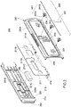
FIG. 1 is an exploded view of the present disclosure. -
FIG. 2 is an exploded view of a waterproof lid structure of the present disclosure. -
FIG. 3 is a front view of an aspect of the present disclosure. -
FIG. 4 is a cross-sectional top view taken along line 4-4 ofFIG. 3 . -
FIG. 5 is a front view of another aspect of the present disclosure. -
FIG. 6 is a cross-sectional top view taken along line 6-6 ofFIG. 5 . - The technical features of the present disclosure are depicted by accompanying drawings and described below. However, the accompanying drawings are illustrative rather than restrictive of the present disclosure.
- The present disclosure provides an electronic device. Referring to
FIG. 1 andFIG. 2 , the electronic device essentially comprises acasing 100 and awaterproof lid structure 200. - In this embodiment, the
casing 100 is made of aluminum or plastic, but the present disclosure is not limited thereto. Thecasing 100 has achamber 100A for receiving a battery (not shown). Thecasing 100 has anopening 110 in communication with thechamber 100A. In this embodiment, the opening 110 is oblong. The accompanying drawings show theopening 110 and its surroundings rather than the whole of thecasing 100 for the sake of illustration, and the other parts of thecasing 100 are not restrictive of the present disclosure. - The
waterproof lid structure 200 corresponds in position to theopening 110 and looks like a door substantially. Thewaterproof lid structure 200 essentially comprises asupportive sheet metal 211, awaterproof component 220, amovable latch lid 230 and a plurality ofbolts 241. - The
supportive sheet metal 211 corresponds in shape to theopening 110 and thus is an oblong sheet metal plate made of stainless steel, but the present disclosure is not limited thereto. For example, thesupportive sheet metal 211 may also be provided in the form of any other metal plate of high mechanical strength. Thesupportive sheet metal 211 has anaxle 211A. Theaxle 211A is pivotally connected to one side of theopening 110. Thesupportive sheet metal 211 is penetrated by a plurality of throughholes 211B. The throughholes 211B are equidistantly disposed along the longitudinal direction of thesupportive sheet metal 211. In this embodiment, theaxle 211A of thesupportive sheet metal 211 is further connected to two securingsheet metals 212. The securingsheet metals 212 are fixed to one side of theopening 110 through two screwing elements A to allow thesupportive sheet metal 211 to turn over relative to the securingsheet metals 212 through theaxle 211A. - The
waterproof component 220 corresponds in shape to thesupportive sheet metal 211 and thus is oblong. In this embodiment, thewaterproof component 220 comprises ajoint portion 221 and aseal portion 222 which are connected. Thejoint portion 221 is made of hard plastic, whereas theseal portion 222 is made of soft plastic (for example, silica gel or rubber), and both are coupled together by bi-injection to manufacture thewaterproof component 220. Thejoint portion 221 is disposed on one side of thesupportive sheet metal 211 and corresponds in position to theopening 110. Theseal portion 222 hermetically seals theopening 110. Therefore, thesoft seal portion 222 hermetically seals theopening 110 effectively by resilient deformation to thereby attain a minimum waterproof and dustproof rating of IP66. The tolerance of thejoint portion 221 made of plastic is effectively controlled during a production process to enable thejoint portion 221 to snap-engage with thesupportive sheet metal 211. A plurality ofpositioning posts 221A are protrudingly disposed at thejoint portion 221 of thewaterproof component 220 and correspond in position to the throughholes 211B of thesupportive sheet metal 211, respectively. The positioning posts 221A pass through the throughholes 211B, respectively. Therefore, thesupportive sheet metal 211 and thewaterproof component 220 position each other. - The
movable latch lid 230 corresponds in shape to thesupportive sheet metal 211 and thus is oblong. In this embodiment, themovable latch lid 230 is made of plastic to reduce the weight of the waterproof lid, but the present disclosure is not limited thereto. Themovable latch lid 230 covers the other side of thesupportive sheet metal 211 to thereby face away from thewaterproof component 220. The upper and lower sides of themovable latch lid 230 each extend to form ashield 230A. Theshields 230A shield and enclose the top edge and bottom edge of thewaterproof component 220 and thesupportive sheet metal 211, respectively. Themovable latch lid 230 is penetrated by a plurality ofpassages 231 corresponding in position to the throughholes 211B and the positioning posts 221A, respectively. In this embodiment, thepassages 231 are counterbores, whereas thepassages 231 extend in a direction parallel to theaxle 211A, allowing the positioning posts 221A to abut against thepassages 231 after passing through the throughholes 211B, respectively. - The
bolts 241 correspond in position to thepassages 231 and the positioning posts 221A, respectively. Thebolts 241 each comprise arod portion 241A and ahead portion 241B disposed at one end of therod portion 241A. The other ends of therod portions 241A pass through thepassages 231 and thesupportive sheet metal 211 so as to be fastened and fixed to the positioning posts 221A of thewaterproof component 220, respectively. Thehead portions 241B stop at the outer side of themovable latch lid 230. Therefore, thewaterproof component 220 and themovable latch lid 230 can be fixed together, and themovable latch lid 230 can move leftward and rightward relative to thesupportive sheet metal 211, allowing the displacement of themovable latch lid 230 to be limited by the length of extension of thepassages 231. - A
handle 232 is protrudingly disposed on the outer side of themovable latch lid 230 and disposed between any two adjacent ones of thepassages 231. In this embodiment, thehandle 232 is slender and perpendicular to the direction of extension of themovable latch lid 230, such that users can easily push thehandle 232 to trigger the leftward and rightward movement of themovable latch lid 230. Furthermore, at least alatch portion 233 is protrudingly disposed on theshield 230A lying above themovable latch lid 230. Theopening 110 of thecasing 100 has at least afastening groove 111 corresponding in position to thelatch portion 233. In this embodiment, both thelatch portion 233 and thefastening groove 111 are in the number of three, whereas thelatch portions 233 are each a bump, and thefastening grooves 111 each have a slot, but the present disclosure is not limited thereto. - Referring to
FIG. 3 andFIG. 4 , when users push thehandle 232, themovable latch lid 230 moves along the direction of extension of thepassages 231 to reach a fastening position, such that thelatch portions 233 in the form of bumps are latched into thefastening grooves 111, so as to fix thewaterproof lid structure 200 in place and prevent it from opening. Referring toFIG. 5 andFIG. 6 , to open thewaterproof lid structure 200, users push thehandle 232 reversely, such that themovable latch lid 230 moves to an unlocked position, triggering the separation of thelatch portions 233 from the slots of thefastening grooves 111. Therefore, thelatch portions 233 and thefastening grooves 111 address the durability issue better than hook-based engagement in terms of the fixation of thewaterproof lid structure 200. In addition, thewaterproof lid structure 200 has thesupportive sheet metal 211 and thus is structurally stronger than its conventional counterparts which are entirely made of plastic, and thewaterproof lid structure 200 is not predisposed to damage and deformation even after long use. - In this embodiment, the
bolts 241, the throughholes 211B and the positioning posts 221A are each in the number of three, but the present disclosure is not limited thereto. For example, thebolts 241, the throughholes 211B and the positioning posts 221A may each be in the number of two or four. Thesupportive sheet metal 211 further has aslot 211C. In this embodiment, theslot 211C lies above the middle one of the throughholes 211B. Adowel 221B corresponding in position to theslot 211C is protrudingly disposed at thejoint portion 221 of thewaterproof component 220. Thedowel 221B is penetratingly disposed at theslot 211C. Aresilient hook 234 corresponding in position to thedowel 221B is disposed at themovable latch lid 230. Theresilient hook 234 is engagingly fitted to thedowel 221B upon the axial movement of themovable latch lid 230. Referring toFIG. 3 andFIG. 5 , users confirm whether themovable latch lid 230 has moved to a fastening position or a release position by observing variations in engagingly fitting theresilient hook 234 to the left and right sides of thedowel 221B. - Referring to
FIG. 2 , preferably, thewaterproof lid structure 200 of the present disclosure further comprises amagnet 250 and adecorative plate 260. Thejoint portion 221 of thewaterproof component 220 has a receivingchamber 221C. Thesupportive sheet metal 211 is penetrated by a magnet through-hole 211D. Themagnet 250 is received in the receivingchamber 221C and penetrates the magnet through-hole 211D so as to be clamped by themovable latch lid 230. Therefore, themagnet 250 works along with a detector (not shown) disposed in theopening 110 to detect whether thewaterproof lid structure 200 is opened or shut. Thedecorative plate 260 is a slender plastic plate penetrated by a handle through-hole 261. Thedecorative plate 260 is engagingly disposed on the outer side of themovable latch lid 230. Thehandle 232 is protruded from the handle through-hole 261 and exposed from thedecorative plate 260. Therefore, thedecorative plate 260 conceals thepassages 231,bolts 241 andresilient hook 234 to ensure the neat, visually pleasing appearance of thewaterproof lid structure 200. Moreover, thehandle 232 protruding from the handle through-hole 261 is easy to push by users. - The present disclosure further provides a method of assembling an electronic device, as described below. The positioning posts 221A of the
waterproof component 220 pass through the throughholes 211B on thesupportive sheet metal 211, respectively, such that thewaterproof component 220 is disposed on one side of thesupportive sheet metal 211. Then, themovable latch lid 230 covers the other side of thesupportive sheet metal 211, such that thepositioning posts 221A abuttingly fit to thepassages 231 on themovable latch lid 230, respectively. Next, therod portions 241A of thebolts 241 pass from the outer side of themovable latch lid 230 through thepassages 231, respectively, and pass through thesupportive sheet metal 211 before being fastened and fixed to the positioning posts 221A of thewaterproof component 220, respectively, thereby allowing thehead portion 241B to stop at the outer side of themovable latch lid 230 and fixing themovable latch lid 230 to thewaterproof component 220. After that, theaxle 211A of thesupportive sheet metal 211 is pivotally connected to one side of theopening 110, and thewaterproof lid structure 200 is shut to cause theseal portion 222 of thewaterproof component 220 to cover and hermetically seal theopening 110. Finally, users push thehandle 232 to drive themovable latch lid 230 to move to the fastening position and cause theresilient hook 234 to engagingly fit to the right side of thedowel 221B, thereby allowing thelatch portions 233 to be latched into thefastening grooves 111 to fasten themovable latch lid 230 in place. - The present disclosure further provides an electronic device. Referring to
FIG. 1 andFIG. 2 , the electronic device essentially comprises acasing 100 and awaterproof lid structure 200. - In this embodiment, the
casing 100 is made of aluminum or plastic, but the present disclosure is not limited thereto. Thecasing 100 has achamber 100A for receiving a battery (not shown) and has anopening 110 in communication with thechamber 100A. In this embodiment, theopening 110 is oblong. The accompanying drawings show theopening 110 and its surroundings rather than the whole of thecasing 100 for the sake of illustration, and the other parts of thecasing 100 are not restrictive of the present disclosure. - The
waterproof lid structure 200 corresponds in position to theopening 110 and looks like a door substantially. Thewaterproof lid structure 200 essentially comprises abase 210, awaterproof component 220, amovable latch lid 230 and a plurality ofcoupling elements 240. - The
base 210 is penetrated by a plurality of throughholes 211B and pivotally disposed on one side of theopening 110. In this embodiment, thebase 210 comprises asupportive sheet metal 211 and two securingsheet metals 212. Thesupportive sheet metal 211 corresponds in shape to theopening 110 and is a slender sheet metal plate made of stainless steel, but the present disclosure is not limited thereto. For example, thesupportive sheet metal 211 can be any other metal plate of high mechanical strength. The throughholes 211B are disposed on thesupportive sheet metal 211. The throughholes 211B are equidistantly disposed along the longitudinal direction of thesupportive sheet metal 211. The securingsheet metals 212 are fixed to one side of theopening 110 through two screwing elements A. Thesupportive sheet metal 211 is pivotally fitted to the securingsheet metals 212 and thus can turn over relative to the securingsheet metals 212. - The
waterproof component 220 corresponds in shape to thesupportive sheet metal 211 and thus is oblong. In this embodiment, thewaterproof component 220 comprises ajoint portion 221 and aseal portion 222 which are connected. Thejoint portion 221 is made of hard plastic. Theseal portion 222 is made of soft plastic (for example, silica gel or rubber), and both are coupled together by bi-injection to manufacture thewaterproof component 220. Thejoint portion 221 is disposed on one side of thesupportive sheet metal 211 and corresponds in position to theopening 110. Theseal portion 222 hermetically seals theopening 110. Therefore, thesoft seal portion 222 hermetically seals theopening 110 effectively by resilient deformation to thereby attain a minimum waterproof and dustproof rating of IP66. The tolerance of thejoint portion 221 made of plastic is effectively controlled during a production process to enable thejoint portion 221 to snap-engage with thesupportive sheet metal 211. A plurality ofpositioning posts 221A are protrudingly disposed at thejoint portion 221 of thewaterproof component 220 and correspond in position to the throughholes 211B of thesupportive sheet metal 211, respectively. The positioning posts 221A pass through the throughholes 211B, respectively. Therefore, thesupportive sheet metal 211 and thewaterproof component 220 position each other. - The
movable latch lid 230 corresponds in shape to thesupportive sheet metal 211 and thus is oblong. In this embodiment, themovable latch lid 230 is made of plastic to reduce the weight of the waterproof lid, but the present disclosure is not limited thereto. Themovable latch lid 230 covers the other side of thesupportive sheet metal 211 to thereby face away from thewaterproof component 220. The upper and lower sides of themovable latch lid 230 each extend to form ashield 230A. Theshields 230A shield and enclose the top edge and bottom edge of thewaterproof component 220 and thesupportive sheet metal 211, respectively. Themovable latch lid 230 is penetrated by a plurality ofpassages 231 corresponding in position to the throughholes 211B and the positioning posts 221A, respectively. In this embodiment, thepassages 231 are counterbores, whereas thepassages 231 extend in a direction parallel to theaxle 211A, allowing the positioning posts 221A to abut against thepassages 231 after passing through the throughholes 211B, respectively. - The
coupling elements 240 correspond in position to thepassages 231 and the positioning posts 221A, respectively. In this embodiment, thecoupling elements 240 are step bolts. Thecoupling elements 240 each comprise arod portion 241A and ahead portion 241B disposed at one end of therod portion 241A. The other ends of therod portions 241A pass through thepassages 231 and then pass through the throughholes 211B of thesupportive sheet metal 211 before being fastened to the positioning posts 221A of thewaterproof component 220, respectively, allowing thehead portions 241B to stop at the outer sides of thepassages 231 of themovable latch lid 230, respectively. Therefore, thewaterproof component 220 and themovable latch lid 230 are fixed together. Owing to thepassages 231, it is feasible for themovable latch lid 230 to slide along therod portion 241A and thus move leftward and rightward relative to thesupportive sheet metal 211, and the displacement of themovable latch lid 230 is limited by the length of extension of thepassages 231. - A
handle 232 is protrudingly disposed on the outer side of themovable latch lid 230 and between any two adjacent ones of thepassages 231. In this embodiment, thehandle 232 is slender and perpendicular to the direction of extension of themovable latch lid 230 to render it easy for users to push thehandle 232 and thereby trigger the leftward and rightward movement of themovable latch lid 230. At least alatch portion 233 is protrudingly disposed at theshield 230A lying above themovable latch lid 230, and at least afastening groove 111 corresponding in position to thelatch portion 233 is disposed at theopening 110 of thecasing 100. In this embodiment, thelatch portions 233 and thefastening grooves 111 are each in the number of three, whereas thelatch portions 233 are each a bump, and thefastening grooves 111 each have a slot, but the present disclosure is not limited thereto. - Referring to
FIG. 3 andFIG. 4 , when users push thehandle 232, themovable latch lid 230 moves along the direction of extension of thepassages 231 to reach a fastening position, such that thelatch portions 233 in the form of bumps are latched into thefastening grooves 111, so as to fix thewaterproof lid structure 200 in place and prevent it from opening. Referring toFIG. 5 andFIG. 6 , to open thewaterproof lid structure 200, users push thehandle 232 reversely, such that themovable latch lid 230 moves to an unlocked position, triggering the separation of thelatch portions 233 from the slots of thefastening grooves 111. Therefore, thelatch portions 233 and thefastening grooves 111 address the durability issue better than hook-based engagement in terms of the fixation of thewaterproof lid structure 200. In addition, thewaterproof lid structure 200 has thesupportive sheet metal 211 and thus is structurally stronger than its conventional counterparts which are entirely made of plastic, and thewaterproof lid structure 200 is not predisposed to damage and deformation even after long use. - In this embodiment, the
coupling elements 240, throughholes 211B andpositioning posts 221A are in the number of three, respectively, but the present disclosure is not limited thereto. For example, thecoupling elements 240, throughholes 211B andpositioning posts 221A may also be in the number of two or four, respectively. Thesupportive sheet metal 211 further has aslot 211C. In this embodiment, theslot 211C lies above the middle one of the throughholes 211B. Adowel 221B corresponding in position to theslot 211C is protrudingly disposed at thejoint portion 221 of thewaterproof component 220. Thedowel 221B is penetratingly disposed at theslot 211C. Aresilient hook 234 corresponding in position to thedowel 221B is disposed at themovable latch lid 230. Theresilient hook 234 is engagingly fitted to thedowel 221B upon the axial movement of themovable latch lid 230. Referring toFIG. 3 andFIG. 5 , users confirm whether themovable latch lid 230 has moved to a fastening position or a release position by observing variations in engagingly fitting theresilient hook 234 to the left and right sides of thedowel 221B. - Referring to
FIG. 2 , preferably, thewaterproof lid structure 200 of the present disclosure further comprises amagnet 250 and adecorative plate 260. A receivingchamber 221C is disposed at thejoint portion 221 of thewaterproof component 220. A magnet through-hole 211D is penetratingly disposed at thesupportive sheet metal 211. Themagnet 250 is received in the receivingchamber 221C and penetrates the magnet through-hole 211D so as to be held by themovable latch lid 230. Therefore, themagnet 250 works along with a detector (not shown) disposed in theopening 110 to detect whether thewaterproof lid structure 200 is opened or shut. Thedecorative plate 260 is a slender plastic plate penetrated by a handle through-hole 261. Thedecorative plate 260 is engagingly disposed on the outer side of themovable latch lid 230. Thehandle 232 is protruded from the handle through-hole 261 and exposed from thedecorative plate 260. Therefore, thedecorative plate 260 conceals thepassages 231,bolts 241 andresilient hook 234 to ensure the neat, visually pleasing appearance of thewaterproof lid structure 200. Moreover, thehandle 232 protruding from the handle through-hole 261 is easy to push by users. - A method of assembling an electronic device according to the present disclosure is described below. The positioning posts 221A of the
waterproof component 220 pass through the throughholes 211B on thesupportive sheet metal 211 of thebase 210, respectively, to position thewaterproof component 220 on one side of thesupportive sheet metal 211. Then, themovable latch lid 230 covers the other side of thesupportive sheet metal 211 to allow the positioning posts 221A to abuttingly fit to thepassages 231 on themovable latch lid 230, respectively. Next, therod portions 241A of thecoupling elements 240 pass from the outer side of themovable latch lid 230 through thepassages 231 and then through the throughholes 211B of thesupportive sheet metal 211 before being fastened and fixed to the positioning posts 221A of thewaterproof component 220, respectively, so as for thehead portions 241B to stop at the outer side of themovable latch lid 230, for themovable latch lid 230 to be fixed to thewaterproof component 220, and for themovable latch lid 230 to slide relative to therod portions 241A through thepassages 231. After that, the securingsheet metals 212 of the base 210 are fixed to one side of theopening 110 to allow thesupportive sheet metal 211 to rotate relative to the securingsheet metals 212, and thewaterproof lid structure 200 is shut to allow theseal portion 222 of thewaterproof component 220 to cover and hermetically seal theopening 110. Finally, users push thehandle 232 to drive themovable latch lid 230 to move along the direction of extension of thepassages 231 to thereby reach a fastening position and cause theresilient hook 234 to engagingly fit to the right side of thedowel 221B, allowing thelatch portions 233 to be latched into thefastening grooves 111 to thereby fasten themovable latch lid 230 in place. - In conclusion, the present disclosure meets the three requirements of patentability, namely industrial applicability, novelty and non-obviousness. Persons skilled in the art can make various changes and variations to the embodiments of the present disclosure without departing from the spirit and essence of the present disclosure. The changes and variations shall be deemed falling within the scope of the claims of the present disclosure.
Claims (16)
- An electronic device, comprising:a casing having an opening;a waterproof lid structure corresponding in position to the opening and comprising:a supportive sheet metal having an axle, with the axle pivotally connected to a side of the opening;a waterproof component for hermetically sealing the opening, with the waterproof component disposed on a side of the supportive sheet metal and corresponding in position to the opening;a movable latch lid for covering another side of the supportive sheet metal, with the movable latch lid penetrated by a plurality of passages; anda plurality of bolts corresponding in position to the passages, respectively, the bolts each comprising a rod portion and a head portion disposed at an end of the rod portion, wherein the rod portions pass through the passages and the supportive sheet metal, respectively, and another end of each said rod portion is fastened to the waterproof component, allowing the head portion to stop at an outer side of the movable latch lid.
- The electronic device of claim 1, wherein the passages extend in a direction parallel to the axle.
- The electronic device of claim 2, wherein a handle is protrudingly disposed on an outer side of the movable latch lid, whereas a latch portion is disposed on an inner side of the movable latch lid, wherein the opening has a fastening groove corresponding in position to the latch portion, such that the handle can be pushed to cause the movable latch lid to move along the direction of extension of the passages to a fastening position, allowing the latch portion to be latched into the fastening groove, and allowing the displacement of the movable latch lid to be limited by the length of extension of the passages.
- The electronic device of claim 3, wherein the supportive sheet metal has a slot, whereas a dowel corresponding in position to the slot is protrudingly disposed at the waterproof component and penetratingly disposed at the slot, wherein the movable latch lid has a resilient hook corresponding in position to the dowel, with the resilient hook adapted to be engagedly fitted to the dowel upon axial movement of the movable latch lid.
- The electronic device of claim 1, wherein a plurality of positioning posts are protrudingly disposed on a side of the waterproof component and positioned proximate to the supportive sheet metal, and the supportive sheet metal has a plurality of through holes corresponding in position to the positioning posts, respectively, wherein the positioning posts pass through the through holes and thereby abuttingly fit to the movable latch lid.
- The electronic device of claim 5, wherein the positioning posts correspond in position to the bolts, respectively, and the bolts are fastened to the positioning posts, respectively.
- A method of assembling an electronic device, comprising the steps of:a) providing a casing, a supportive sheet metal, a waterproof component, a movable latch lid and a plurality of bolts, the casing having an opening, the supportive sheet metal having an axle, the movable latch lid being penetrated by a plurality of passages, the bolts corresponding in position to the passages, respectively, the bolts each comprising a rod portion and a head portion disposed at an end of the rod portion;b) positioning the waterproof component on a side of the supportive sheet metal and covering another side of the supportive sheet metal with the movable latch lid;c) passing the rod portions of the bolts from an outer side of the movable latch lid through the passages, respectively, and through the supportive sheet metal before being fastened to the waterproof component, thereby allowing the head portion to stop at the outer side of the movable latch lid; andd) connecting pivotally the axle of the supportive sheet metal to a side of the opening,
wherein the waterproof component covers and hermetically seals the opening. - The method of claim 7, wherein a latch portion is disposed on an inner side of the movable latch lid, and the opening has a fastening groove corresponding in position to the latch portion, allowing the movable latch lid to move along the direction of extension of the passages, and allowing the latch portion to be latched into the fastening groove to thereby fastening the movable latch lid in place.
- The method of claim 8, wherein the supportive sheet metal has a slot, whereas a dowel corresponding in position to the slot is protrudingly disposed at the waterproof component and penetratingly disposed at the slot, wherein the movable latch lid has a resilient hook corresponding in position to the dowel, with the resilient hook adapted to be engagedly fitted to the dowel upon axial movement of the movable latch lid.
- The method of claim 7, wherein a plurality of positioning posts are protrudingly disposed on a side of the waterproof component and positioned proximate to the supportive sheet metal, and the supportive sheet metal has a plurality of through holes corresponding in position to the positioning posts, respectively, wherein the method further comprises the step of allowing the positioning posts to pass through the through holes and thereby abuttingly fit to the movable latch lid.
- The method of claim 10, wherein the positioning posts correspond in position to the bolts, respectively, and the method further comprises the step of fastening the bolts to the positioning posts, respectively.
- An electronic device, comprising:a casing having an opening;a waterproof lid structure corresponding in position to the opening and comprising:a base penetrated by a through hole and pivotally disposed on a side of the opening;a waterproof component disposed on a side of the base to hermetically seal the opening;a movable latch lid penetrated by a passage and disposed on another side of the base; anda coupling element comprising a rod portion and a head portion disposed at an end of the rod portion, the rod portion passing through the passage and then passing through the through hole, the head portion stopping at an outer side of the passage, wherein another end of the rod portion is fixed to the waterproof component, and the movable latch lid slides along the rod portion through the passage.
- The electronic device of claim 12, wherein the coupling element is a step bolt.
- The electronic device of claim 12, wherein the base comprises a supportive sheet metal and a securing sheet metal, the supportive sheet metal being penetrated by the through hole, and the securing sheet metal being fixed to a side of the opening, wherein the supportive sheet metal is pivotally connected to the securing sheet metal.
- A method of assembling an electronic device, comprising the steps of:a) providing a casing, a base, a waterproof component, a movable latch lid and a coupling element, the casing having an opening, the base being penetrated by a through hole, the movable latch lid being penetrated by a passage, and the coupling element comprising a rod portion and a head portion disposed at an end of the rod portion;b) positioning the waterproof component on a side of the base and positioning the movable latch lid on another side of the base;c) passing the rod portion through the passage and then through the through hole, allowing the head portion to stop at an outer side of the passage, allowing another end of the rod portion to be fixed to the waterproof component, allowing the movable latch lid to slide along the rod portion through the passage; andd) connecting pivotally the base to a side of the opening.
- The method of claim 15, wherein a latch portion is disposed on an inner side of the movable latch lid, and the opening has a fastening groove corresponding in position to the latch portion, moving the movable latch lid along the direction of extension of the passage, allowing the latch portion to be latched into the fastening groove, thereby fastening the movable latch lid in place.
Applications Claiming Priority (1)
| Application Number | Priority Date | Filing Date | Title |
|---|---|---|---|
| US202163231196P | 2021-08-09 | 2021-08-09 |
Publications (1)
| Publication Number | Publication Date |
|---|---|
| EP4135492A1 true EP4135492A1 (en) | 2023-02-15 |
Family
ID=82076539
Family Applications (1)
| Application Number | Title | Priority Date | Filing Date |
|---|---|---|---|
| EP22189284.7A Pending EP4135492A1 (en) | 2021-08-09 | 2022-08-08 | Electronic device and method of assembling the same |
Country Status (3)
| Country | Link |
|---|---|
| US (1) | US20230038904A1 (en) |
| EP (1) | EP4135492A1 (en) |
| CN (1) | CN114679865A (en) |
Families Citing this family (1)
| Publication number | Priority date | Publication date | Assignee | Title |
|---|---|---|---|---|
| US11940854B2 (en) * | 2022-02-11 | 2024-03-26 | Getac Technology Corporation | Replacement device and electronic device |
Citations (2)
| Publication number | Priority date | Publication date | Assignee | Title |
|---|---|---|---|---|
| US20170340078A1 (en) * | 2016-05-24 | 2017-11-30 | Hong Fu Jin Precision Industry (Shenzhen) Co., Ltd. | Protective housing and cover mechanism thereof |
| CN112153843A (en) * | 2019-06-28 | 2020-12-29 | 神讯电脑(昆山)有限公司 | Electronic device with door cover |
Family Cites Families (27)
| Publication number | Priority date | Publication date | Assignee | Title |
|---|---|---|---|---|
| CN1183429C (en) * | 2002-08-30 | 2005-01-05 | 广达电脑股份有限公司 | Mechanism for sliding upper cover of mainfram |
| TW200834285A (en) * | 2007-02-02 | 2008-08-16 | Compal Electronics Inc | Fastening structure for reducing surface temperature of housing |
| TW200847891A (en) * | 2007-05-25 | 2008-12-01 | Mitac Technology Corp | Movable engaging door structure |
| JP5444741B2 (en) * | 2008-03-03 | 2014-03-19 | パナソニック株式会社 | Electronics |
| CN101901883B (en) * | 2009-05-25 | 2013-06-19 | 佛山普立华科技有限公司 | Battery cover |
| CN102541161B (en) * | 2010-12-10 | 2013-10-30 | 神基科技股份有限公司 | Clamping door structure |
| CN104582346B (en) * | 2013-10-18 | 2017-09-22 | 神讯电脑(昆山)有限公司 | The water door component of electronic installation |
| CN104750196B (en) * | 2013-12-27 | 2018-11-06 | 神讯电脑(昆山)有限公司 | Waterproof knocker and its automatic pressure-regulating type plug member group |
| CN105321210B (en) * | 2014-07-28 | 2018-02-27 | 神讯电脑(昆山)有限公司 | Gate structure is with applying its electronic installation |
| WO2017077671A1 (en) * | 2015-11-06 | 2017-05-11 | パナソニックIpマネジメント株式会社 | Electronic device and electronic device terminal cover |
| US9668370B1 (en) * | 2016-04-27 | 2017-05-30 | Getac Technology Corporation | Door of electronic device |
| TWM528296U (en) * | 2016-05-02 | 2016-09-11 | Chung King Entpr Co Ltd | Latch mechanism and wafer cassette having the same |
| CN107426933B (en) * | 2016-05-24 | 2019-08-30 | 南宁富桂精密工业有限公司 | Electronic device and its sealing mechanism |
| TWI604298B (en) * | 2017-01-05 | 2017-11-01 | 緯創資通股份有限公司 | Electronic module ejecting mechanism and portable electronic device thereof |
| US10050374B1 (en) * | 2017-06-01 | 2018-08-14 | Getac Technology Corporation | Device with waterproof structure |
| CN107317090A (en) * | 2017-07-14 | 2017-11-03 | 广东通宇通讯股份有限公司 | Antenna waterproof installs case, earth's surface antenna and antenna system |
| JP2019102764A (en) * | 2017-12-08 | 2019-06-24 | 株式会社Jvcケンウッド | Waterproof open and close lid structure and electronic equipment including the same |
| CN207932170U (en) * | 2018-02-28 | 2018-10-02 | 南通嘉奇钣金科技有限公司 | A kind of sheet metal box body |
| CN110764569A (en) * | 2018-07-25 | 2020-02-07 | 神讯电脑(昆山)有限公司 | Latch mechanism and tenon structure thereof |
| CN209556141U (en) * | 2018-10-22 | 2019-10-29 | 正知(上海)智能技术有限公司 | A kind of embedded wall enclosure attachment device of HMI |
| CN109698289B (en) * | 2018-12-26 | 2022-01-07 | 重庆蓝岸通讯技术有限公司 | Battery cover locking device and portable electronic equipment |
| US11337319B2 (en) * | 2019-04-16 | 2022-05-17 | Getac Technology Corporation | Latch structure and device with the same |
| CN112558707A (en) * | 2019-09-25 | 2021-03-26 | 神讯电脑(昆山)有限公司 | Latch structure and device with same |
| CN211826991U (en) * | 2020-06-14 | 2020-10-30 | 林州中谷物联网络科技有限公司 | Intelligent switch |
| US20210405144A1 (en) * | 2020-06-25 | 2021-12-30 | Getac Technology Corporation | Electronic device |
| CN212515158U (en) * | 2020-08-06 | 2021-02-09 | 青岛璐丰赢电子科技有限公司 | Outdoor waterproof dustproof panel beating divides fine case |
| CN114253352A (en) * | 2020-09-23 | 2022-03-29 | 神讯电脑(昆山)有限公司 | Door cover structure of mobile device |
-
2022
- 2022-03-30 CN CN202210332113.6A patent/CN114679865A/en active Pending
- 2022-08-08 US US17/883,479 patent/US20230038904A1/en active Pending
- 2022-08-08 EP EP22189284.7A patent/EP4135492A1/en active Pending
Patent Citations (2)
| Publication number | Priority date | Publication date | Assignee | Title |
|---|---|---|---|---|
| US20170340078A1 (en) * | 2016-05-24 | 2017-11-30 | Hong Fu Jin Precision Industry (Shenzhen) Co., Ltd. | Protective housing and cover mechanism thereof |
| CN112153843A (en) * | 2019-06-28 | 2020-12-29 | 神讯电脑(昆山)有限公司 | Electronic device with door cover |
Also Published As
| Publication number | Publication date |
|---|---|
| US20230038904A1 (en) | 2023-02-09 |
| CN114679865A (en) | 2022-06-28 |
Similar Documents
| Publication | Publication Date | Title |
|---|---|---|
| AU2018101670B4 (en) | Hinge | |
| CN213980451U (en) | Modular glass door | |
| EP1842705B1 (en) | Supporting module for vehicle doors and mounting procedure for said module | |
| EP4135492A1 (en) | Electronic device and method of assembling the same | |
| JPS62134327A (en) | Door structure for automobile | |
| EP1867560A4 (en) | Bonnet structure for working vehicle | |
| US20120068586A1 (en) | Enclosure Corner Seals and Assemblies | |
| KR20180055937A (en) | Handle for Opening and Closing Sliding Door | |
| WO2010018704A1 (en) | Door panel | |
| US9714536B2 (en) | Door frames with energy absorbing door stops | |
| JP5056233B2 (en) | Vehicle door structure | |
| KR20180086171A (en) | Handle for Opening and Closing Sliding Door | |
| CN114961474B (en) | Hinge assembly mounting method, hinge assembly used by hinge assembly mounting method and refrigeration equipment | |
| KR200452186Y1 (en) | Reclaming type window locking device | |
| KR101234386B1 (en) | Double window structure of sliding door integrated opening and shutting | |
| KR20090108725A (en) | Vehicle door | |
| KR101905934B1 (en) | Window having a wood cover | |
| KR200452139Y1 (en) | A locking device for opening and shutting windows | |
| EP3348771A1 (en) | Window ventilation system and window | |
| CN216921765U (en) | Door hinge with good covering performance | |
| CN217623075U (en) | Door and vehicle | |
| CN216921756U (en) | Door and window locking device | |
| CN219864651U (en) | Section bar hardware mounting structure, hinged system of outward opening door and window and door and window system | |
| CN218806207U (en) | Sealing member, door window, door and vehicle | |
| CN214576413U (en) | Hinge with elastic hinge |
Legal Events
| Date | Code | Title | Description |
|---|---|---|---|
| PUAI | Public reference made under article 153(3) epc to a published international application that has entered the european phase |
Free format text: ORIGINAL CODE: 0009012 |
|
| STAA | Information on the status of an ep patent application or granted ep patent |
Free format text: STATUS: THE APPLICATION HAS BEEN PUBLISHED |
|
| AK | Designated contracting states |
Kind code of ref document: A1 Designated state(s): AL AT BE BG CH CY CZ DE DK EE ES FI FR GB GR HR HU IE IS IT LI LT LU LV MC MK MT NL NO PL PT RO RS SE SI SK SM TR |
|
| STAA | Information on the status of an ep patent application or granted ep patent |
Free format text: STATUS: REQUEST FOR EXAMINATION WAS MADE |
|
| 17P | Request for examination filed |
Effective date: 20230815 |
|
| RBV | Designated contracting states (corrected) |
Designated state(s): AL AT BE BG CH CY CZ DE DK EE ES FI FR GB GR HR HU IE IS IT LI LT LU LV MC MK MT NL NO PL PT RO RS SE SI SK SM TR |