EP4135316B1 - Verfahren und vorrichtung zur dynamikbereichsabbildung - Google Patents
Verfahren und vorrichtung zur dynamikbereichsabbildung Download PDFInfo
- Publication number
- EP4135316B1 EP4135316B1 EP21796388.3A EP21796388A EP4135316B1 EP 4135316 B1 EP4135316 B1 EP 4135316B1 EP 21796388 A EP21796388 A EP 21796388A EP 4135316 B1 EP4135316 B1 EP 4135316B1
- Authority
- EP
- European Patent Office
- Prior art keywords
- parameter
- curve
- value
- luminance
- tone mapping
- Prior art date
- Legal status (The legal status is an assumption and is not a legal conclusion. Google has not performed a legal analysis and makes no representation as to the accuracy of the status listed.)
- Active
Links
Images


Classifications
-
- G—PHYSICS
- G06—COMPUTING OR CALCULATING; COUNTING
- G06T—IMAGE DATA PROCESSING OR GENERATION, IN GENERAL
- G06T5/00—Image enhancement or restoration
- G06T5/90—Dynamic range modification of images or parts thereof
-
- G—PHYSICS
- G06—COMPUTING OR CALCULATING; COUNTING
- G06T—IMAGE DATA PROCESSING OR GENERATION, IN GENERAL
- G06T5/00—Image enhancement or restoration
- G06T5/90—Dynamic range modification of images or parts thereof
- G06T5/92—Dynamic range modification of images or parts thereof based on global image properties
-
- G—PHYSICS
- G06—COMPUTING OR CALCULATING; COUNTING
- G06V—IMAGE OR VIDEO RECOGNITION OR UNDERSTANDING
- G06V10/00—Arrangements for image or video recognition or understanding
- G06V10/40—Extraction of image or video features
- G06V10/60—Extraction of image or video features relating to illumination properties, e.g. using a reflectance or lighting model
-
- G—PHYSICS
- G09—EDUCATION; CRYPTOGRAPHY; DISPLAY; ADVERTISING; SEALS
- G09G—ARRANGEMENTS OR CIRCUITS FOR CONTROL OF INDICATING DEVICES USING STATIC MEANS TO PRESENT VARIABLE INFORMATION
- G09G3/00—Control arrangements or circuits, of interest only in connection with visual indicators other than cathode-ray tubes
- G09G3/20—Control arrangements or circuits, of interest only in connection with visual indicators other than cathode-ray tubes for presentation of an assembly of a number of characters, e.g. a page, by composing the assembly by combination of individual elements arranged in a matrix no fixed position being assigned to or needed to be assigned to the individual characters or partial characters
- G09G3/34—Control arrangements or circuits, of interest only in connection with visual indicators other than cathode-ray tubes for presentation of an assembly of a number of characters, e.g. a page, by composing the assembly by combination of individual elements arranged in a matrix no fixed position being assigned to or needed to be assigned to the individual characters or partial characters by control of light from an independent source
- G09G3/3406—Control of illumination source
-
- H—ELECTRICITY
- H04—ELECTRIC COMMUNICATION TECHNIQUE
- H04N—PICTORIAL COMMUNICATION, e.g. TELEVISION
- H04N9/00—Details of colour television systems
- H04N9/77—Circuits for processing the brightness signal and the chrominance signal relative to each other, e.g. adjusting the phase of the brightness signal relative to the colour signal, correcting differential gain or differential phase
-
- G—PHYSICS
- G06—COMPUTING OR CALCULATING; COUNTING
- G06T—IMAGE DATA PROCESSING OR GENERATION, IN GENERAL
- G06T2207/00—Indexing scheme for image analysis or image enhancement
- G06T2207/10—Image acquisition modality
- G06T2207/10024—Color image
-
- G—PHYSICS
- G06—COMPUTING OR CALCULATING; COUNTING
- G06T—IMAGE DATA PROCESSING OR GENERATION, IN GENERAL
- G06T2207/00—Indexing scheme for image analysis or image enhancement
- G06T2207/20—Special algorithmic details
- G06T2207/20172—Image enhancement details
- G06T2207/20208—High dynamic range [HDR] image processing
-
- G—PHYSICS
- G09—EDUCATION; CRYPTOGRAPHY; DISPLAY; ADVERTISING; SEALS
- G09G—ARRANGEMENTS OR CIRCUITS FOR CONTROL OF INDICATING DEVICES USING STATIC MEANS TO PRESENT VARIABLE INFORMATION
- G09G2320/00—Control of display operating conditions
- G09G2320/06—Adjustment of display parameters
- G09G2320/0626—Adjustment of display parameters for control of overall brightness
Definitions
- This application relates to the field of display technologies, and more specifically, to a dynamic range mapping method and apparatus.
- a dynamic range (DR) indicates a ratio of a maximum value to a minimum value of a variable in many fields.
- a dynamic range indicates a ratio of maximum luminance to minimum luminance in a displayable range of the image, that is, a quantity of grayscale levels obtained through division between a "brightest" part and a "darkest" part of the image.
- a unit of luminance is candela per square meter (cd/m 2 ) or may be represented as nit (nit).
- a larger dynamic range of an image indicates more luminance levels for representing the image and more realistic visual effect of the image.
- a dynamic range of a natural scene in the real world is between 10 -3 and 10 6 .
- the dynamic range is very large, and therefore is referred to as a high dynamic range (HDR).
- HDR high dynamic range
- a common image has a standard dynamic range (SDR) or a low dynamic range (LDR).
- a display device whose dynamic range is less than 0.1 nits to 400 nits is generally referred to as an SDR display device.
- a display device whose dynamic range is greater than 0.01 nits to 540 nits is generally referred to as an HDR display device.
- Different high dynamic range display devices display different dynamic ranges, for example, an HDR display device of 0.01 nits to 540 nits and an HDR display device of 0.005 nits to 1000 nits.
- a dynamic range mapping method is mainly applied to an adaptation process between a front-end HDR signal and a back-end HDR display device, including a tone mapping (tone mapping) process from high to low and a tone mapping process from low to high.
- a front end collects a 4000-nit illumination signal, while a back-end display device has an HDR display capability of only 500 nits. Therefore, mapping the 4000-nit illumination signal to the 500-nit display device is a mapping process from high to low.
- a front end collects a 100-nit SDR illumination signal, while a back-end display device has an HDR display capability of 2000 nits. Therefore, mapping the 100-nit illumination signal to the 2000-nit display device is a mapping process from low to high.
- a mapping algorithm based on a dynamic range of an "S"-shaped curve may be used to adjust a high dynamic range image to a dynamic range that can be displayed by a display device for display.
- the maximum luminance of the image is close to the maximum display luminance of the display device, if the foregoing solution is still used, there is an abnormality that luminance of a pixel of a mapped display device is greater than that of an original image. As a result, user experience is affected.
- US 2018/330674 A1 discloses adjustment of tone mapping parameters for a simultaneous display of low and high dynamic range content on a display, for a transition between low and high dynamic range contents as well as adaptation to changes in the viewing environment.
- This application provides a dynamic range mapping method and apparatus, to help avoid, when maximum display luminance of an image is close to maximum display luminance of a display device, an abnormality that luminance of a pixel of a mapped terminal device is greater than that of an original image.
- a dynamic range mapping method including:
- a parameter of the first tone mapping curve is further adjusted, so that output luminance of a point on a tone mapping curve (that is, the second tone mapping curve) corresponding to an adjusted curve parameter (that is, the second parameter) is not greater than corresponding input luminance of the point.
- the terminal device is, for example, a display device.
- a product form of the display device may be an electronic device such as a set-top box, a television display device, a mobile phone display device, or a conversion device for live webcasting and video applications.
- a solution provided in this embodiment of this application may be implemented in a form of a hardware chip.
- a solution provided in this embodiment of this application are mainly implemented in a form of software program code.
- this embodiment of this application is not limited thereto.
- the image data may be, for example, an HDR source or an SDR source, for example, pixel data in the image, for example, luminance and color data of each pixel.
- the feature information of the image data may be obtained from metadata M of the image data.
- the metadata M may include, for example, a curve parameter M curve corresponding to the image data, targeted system display actual peak luminance M TPL (targeted system display actual peak luminance), a maximum luminance value MaxSource (maximum values of Y components of all pixels, or a maximum value of maximum values of RGB components of all pixels) of content of the image data, a minimum luminance value MinSource (minimum values of Y components of all pixels, or a minimum value of maximum values of RGB components of all pixels), an average value (an average value of Y components of all pixels, or an average value of maximum values of RGB components of all pixels), and a change range of displayed content. This is not limited in this embodiment of this application.
- the feature information of the image data may be further obtained from pixel information of the image data V.
- a feature information value of the image data with a preset value is used. This is not limited in this embodiment of this application.
- the display parameter M TPL of the terminal device may include maximum display luminance MaxDisplay and/or minimum display luminance MinDisplay of the terminal device, or another parameter. This is not limited in this embodiment of this application.
- the preset condition is met when any one of the following conditions is met:
- output luminance at a second point on the first tone mapping curve is greater than input luminance at the second point on the first tone mapping curve.
- a parameter p P1 in the first parameter is greater than a first value Tp.
- the first value Tp is obtained based on a P1 in the first parameter and a preset correspondence between a P1 , and p P1 .
- Tp indicates a threshold of a curve parameter p.
- a parameter a P1 in the first parameter is greater than a second value Ta.
- the second value Ta is obtained based on p P1 in the first parameter and a preset correspondence between a P1 , and p P1 .
- Ta indicates a threshold of a curve parameter a.
- a product of a parameter a P1 and a parameter p P1 , in the first parameter is greater than a third value Tap.
- the third value Tap is a preset rational number.
- output luminance at a point on the second tone mapping curve may be greater than input luminance.
- the third value Tap may be a rational number between 3 and 4, for example, 3.2 or 3.4. This is not limited in this embodiment of this application.
- the second parameter includes a first linear spline curve parameter.
- the first linear spline curve parameter includes a slope MB[0][0] of a first linear spline on the second tone mapping curve and/or a maximum value TH3[0] of a luminance value of a range pixel of the first linear spline and/or an intersection point base_offset of the first linear spline and a vertical coordinate axis.
- a straight line part (that is, the first linear spline) may be used to perform tone mapping in a dark region of the image data.
- a luminance gain can be controlled.
- it is more convenient to control the second parameter to gradually change from a straight line to a straight line y x.
- the first parameter includes a second linear spline curve parameter.
- the second linear spline curve parameter includes a slope MB_mid[0][0] of a second linear spline on the first tone mapping curve and/or a maximum value TH3_mid[0] of a luminance value of a range pixel of the second linear spline.
- the display parameter includes maximum display luminance MaxDisplay of the terminal device.
- the feature information includes a maximum luminance correction value max_lum of the image data.
- the obtaining a second parameter of a second tone mapping curve based on the first parameter, the display parameter, and the feature information includes: adjusting the curve parameters MB_mid[0][0] and TH3_mid[0] based on the maximum display luminance MaxDisplay and the maximum luminance correction value max_lum to obtain the curve parameters MB[0][0] and TH3[0].
- the slope MB[0][0] of the first linear spline on the second tone mapping curve and the maximum value TH3[0] of the luminance value of the range pixel of the first linear spline may be obtained based on the slope MB_mid[0] [0] of the second linear spline on the first tone mapping curve, the maximum value TH3_mid[0] of the luminance value of the range pixel of the second linear spline, the maximum display luminance MaxDisplay of the terminal device, and the maximum luminance correction value max_lum of the image data.
- L is an input signal
- G(L) is an inverse function of a function H(L) corresponding to a tone mapping curve
- m_a, m_b, m_m, m_n, k1, k2, and k3 are curve parameters
- G(L, m_a_T) indicates a G(L) value corresponding to an input variable L when a value of a parameter M_a of G(L) is m_a_T
- N1 and N2 are rational numbers
- max(a, b) indicates calculating a larger value of a and b
- min(a, b) indicates calculating a smaller value of a and b
- the first parameter includes the second linear spline curve parameter.
- the second linear spline curve parameter includes the slope MB_mid[0][0] of the second linear spline on the first tone mapping curve and/or the maximum value TH3_mid[0] of the luminance value of the range pixel of the second linear spline and/or an intersection point base_offset_mid of the first linear spline and the vertical coordinate axis.
- the display parameter includes the maximum display luminance MaxDisplay of the terminal device.
- the feature information includes the maximum luminance correction value max_lum of the image data.
- the obtaining a second parameter of a second tone mapping curve based on the first parameter, the display parameter, and the feature information includes: adjusting the curve parameters MB_mid[0][0], TH3_mid[0], and/or base_offset_mid based on the maximum display luminance MaxDisplay and the maximum luminance correction value max_lum to obtain the curve parameters MB[0][0], TH3[0], and/or base_offset.
- the second parameter includes a cubic spline curve parameter.
- the cubic spline curve parameter includes interpolation point values TH1[1], TH2[1], and TH3[1] of a cubic spline on the second tone mapping curve.
- TH1[1] indicates a minimum value of a luminance value of a first range pixel of the cubic spline.
- TH2[1] indicates a maximum value of the luminance value of the first range pixel of the cubic spline and a minimum value of a luminance value of a second range pixel of the cubic spline.
- TH3[1] indicates a maximum value of the luminance value of the second range pixel of the cubic spline.
- B, C, and D are preset values of the correlation values for calculating the interpolation point values TH1[1], TH2[1], and TH3[1] of the cubic spline.
- B is a preset offset value corresponding to a luminance value of a dark-bright transition region pixel.
- C and D are preset weighting coefficients corresponding to a luminance value of a bright region pixel.
- the interpolation point values TH1[1], TH2[1], and TH3[1] of the cubic spline on the second parameter may be obtained based on the second linear spline curve parameter in the first parameter and the preset offset values of the correlation values for calculating the interpolation point values TH1[1], TH2[1], and TH3[1] of the cubic spline.
- 3Spline_TH_Delta1[i][1][w] are the correlation values that are used for calculating the interpolation point values TH1[1], TH2[1], and TH3[1] of the cubic spine and that are extracted from metadata.
- the interpolation point values TH1[1], TH2[1], and TH3[1] of the cubic spline on the second parameter may be obtained based on the second linear spline curve parameter in the first parameter and the correlation values that are used for calculating the interpolation point values TH1[1], TH2[1], and TH3[1] of the cubic spline and that are extracted from the metadata.
- a Y coordinate of a linear spline on the second tone mapping curve at TH3[0] is the same as a Y coordinate of the cubic spline on the second tone mapping curve at TH1[1]
- a first-order derivative of the linear spline at TH3[0] is the same as a first-order derivative of the cubic spline at TH1[1].
- the linear spline curve in the second tone mapping curve and the cubic spline curve in the second tone mapping curve can be consecutive at TH[1].
- a Y coordinate of a first cubic spline on the second tone mapping curve at TH2[1] is the same as a Y coordinate of a second cubic spline on the second tone mapping curve at TH2[1]
- a first-order derivative of the first cubic spline at TH2[1] is the same as a first-order derivative of the second cubic spline at TH2[1].
- a first cubic spline curve and a second cubic spline curve in the second tone mapping curve can be consecutive at TH[2].
- a Y coordinate of the second cubic spline on the second tone mapping curve at TH3[1] is the same as a Y coordinate of a third tone mapping function on the second tone mapping curve at TH3[1]
- a first-order derivative of the second cubic spline at TH3[1] is the same as a first-order derivative of the third tone mapping function at TH3[1].
- the second cubic spline curve in the second tone mapping curve and a curve of the third tone mapping function can be consecutive at TH[3].
- the obtaining a first parameter of a first tone mapping curve of the image data includes:
- the display device may obtain, based on an average luminance value average_maxrgb, and/or a maximum luminance value MaxSource, and/or a minimum luminance value MinSource of the content of the image data V in the metadata M, and/or maximum display luminance MaxDisplay of the display device, and/or minimum display luminance MinDisplay of the display device, and/or the curve parameter M curve ( p1 , p2, ...), and/or other data, the first parameter of the first tone mapping curve.
- the first parameter may be represented, for example, as P1 curve (X, p1, p2, ). X is an input luminance value, and p1, p2, ... are curve parameter values.
- the second parameter further includes a linear spline curve parameter.
- the linear spline curve parameter includes a maximum value TH3C of a luminance value of a range pixel of the first linear spline on the second tone mapping curve and a slope Dark of the first linear spline.
- the straight line part (that is, the first linear spline) may be used to perform tone mapping in the dark region of the image data.
- the luminance gain can be controlled.
- it is more convenient to control the second parameter to gradually change from the straight line to the straight line y x.
- the method further includes:
- the obtaining a maximum value TH3C0 of a luminance value of an initial range pixel of the first linear spline includes:
- the obtaining an initial slope Dark0 of the first linear spline includes:
- TH3C is greater than TH3C0 and less than MaxSource. TH3C0 is less than MaxSource. N1 and N2 are rational numbers greater than 0.
- H(L) is the tone mapping curve.
- G(L) is the inverse function of H(L).
- MaxLum is an adjustment value of maximum luminance of the image data.
- TH3C is greater than TH3C0 and less than MaxSource.
- TH3C0 is less than MaxSource.
- N1 and N2 are rational numbers greater than 0.
- H(L) is the tone mapping curve function.
- G(L) is the inverse function of H(L).
- the second parameter further includes the cubic spline curve parameter.
- the cubic spline curve parameter includes a minimum value TH1D of a luminance value of a first range pixel of the first cubic spline on the second tone mapping curve.
- the method further includes: determining the minimum value TH1D of the luminance value of the first range pixel based on the maximum value TH3C of the luminance value of the range pixel of the first linear spline on the second tone mapping curve.
- the second parameter further includes the cubic spline curve parameter.
- the cubic spline curve parameter includes a maximum value TH2D of the luminance value of the first range pixel of the first cubic spline on the second tone mapping curve.
- the method further includes: determining the maximum value TH2D of the luminance value of the first range pixel based on the minimum value TH1D of the luminance value of the first range pixel.
- the determining the maximum value TH2D of the luminance value of the first range pixel based on the minimum value TH1D of the luminance value of the first range pixel includes:
- the minimum value TH1D of the luminance value of the first range pixel of the first cubic spline on the second tone mapping curve is the same as the maximum value TH3C of the luminance value of the range pixel of the first linear spline
- output values of the linear spline and the first cubic spline on the second tone mapping curve at TH1D are the same
- first-order derivatives of the first spline and the first cubic spline on the second tone curve at TH1D are the same.
- a linear spline curve in the second tone mapping curve and a cubic spline curve in the second tone mapping curve can be consecutive at TH1D.
- the cubic spline curve parameter further includes a maximum value TH3D of a luminance value of a second range pixel of a second cubic spline on the second tone mapping curve.
- the method further includes: determining the maximum value TH3D of the luminance value of the second range pixel based on the minimum value TH1D of the luminance value of the first range pixel and the maximum value TH2D of the luminance value of the first range pixel.
- the determining the maximum value TH3D of the luminance value of the second range pixel based on the minimum value TH1D of the luminance value of the first range pixel and the maximum value TH2D of the luminance value of the first range pixel includes:
- a minimum value of the luminance value of the second range pixel of the second cubic spline is the same as the maximum value TH2D of the luminance value of the first range pixel of the first cubic spline
- output values of the first cubic spline and the second cubic spline at the maximum value TH2D of the luminance value of the range pixel are the same
- first-order derivatives of the first cubic spline and the second cubic spline at the maximum value TH2D of the luminance value of the range pixel are the same.
- the first cubic spline curve and the second cubic spline curve in the second tone mapping curve can be consecutive at TH2D.
- the second parameter further includes a curve parameter of a tone mapping subfunction of the second tone mapping curve.
- a minimum value of a luminance value of a third range pixel of the tone mapping subfunction is the same as the maximum value TH3D of the luminance value of the second range pixel
- output values of the second cubic spline and the tone mapping subfunction at the maximum value TH3D of the luminance value of the second range pixel are the same
- first-order derivatives of the second cubic spline and the tone mapping subfunction at the maximum value TH3D of the luminance value of the second range pixel are the same.
- the second cubic spline curve in the second tone mapping curve and a curve of the tone mapping subfunction can be consecutive at TH3D.
- the first parameter includes a P1 , and p P1 .
- the obtaining a second parameter of a second tone mapping curve based on the first parameter, the display parameter, and the feature information includes:
- p P1 in the first parameter is replaced with Tp, and the first parameter obtained after replacement is used as the second parameter, so that the output luminance at the first point on the second tone mapping curve is not greater than the input luminance at the first point on the second tone mapping curve.
- the first parameter includes a P1 , and p P1 .
- the obtaining a second parameter of a second tone mapping curve based on the first parameter, the display parameter, and the feature information includes:
- a P1 in the first parameter is replaced with Ta, and the first parameter obtained after replacement is used as the second parameter, so that the output luminance at the first point on the second tone mapping curve is not greater than the input luminance at the first point on the second tone mapping curve.
- the first parameter includes a P1 , and p P1 .
- the obtaining a second parameter of a second tone mapping curve based on the first parameter, the display parameter, and the feature information includes:
- p P1 in the first parameter is replaced with Tap/a P1
- a P1 in the first parameter is replaced with Tap/p P1
- the first parameter obtained after replacement is used as the second parameter, so that the output luminance at the first point on the second tone mapping curve is not greater than the input luminance at the first point on the second tone mapping curve.
- a dynamic range mapping apparatus including an obtaining unit, a processing unit, and a mapping unit.
- the obtaining unit is configured to obtain a display parameter of a terminal device.
- the obtaining unit is further configured to obtain feature information of image data.
- the obtaining unit is further configured to obtain a first parameter of a first tone mapping curve of the image data.
- the processing unit is configured to: when a preset condition is met, obtain a second parameter of a second tone mapping curve based on the first parameter, the display parameter of the terminal device, and the feature information of the image data. Output luminance at a first point on the second tone mapping curve is not greater than input luminance at the first point on the second tone mapping curve.
- the mapping unit is configured to perform dynamic range mapping on the image data based on the second parameter of the second tone mapping curve.
- the preset condition is met when any one of the following conditions is met:
- output luminance at a second point on the first tone mapping curve is greater than input luminance at the second point on the first tone mapping curve.
- a parameter p P1 , in the first parameter is greater than a first value Tp.
- the first value Tp is obtained based on a P1 in the first parameter and a preset correspondence between a P1 , and p P1 .
- a parameter a P1 in the first parameter is greater than a second value Ta.
- the second value Ta is obtained based on p P1 in the first parameter and a preset correspondence between a P1 , and p P1 .
- a product of a parameter a P1 and a parameter p P1 , in the first parameter is greater than a third value Tap.
- the third value Tap is a preset rational number.
- the second parameter includes a first linear spline curve parameter.
- the first linear spline curve parameter includes a slope MB[0][0] of a first linear spline on the second tone mapping curve and/or a maximum value TH3[0] of a luminance value of a range pixel of the first linear spline and/or an intersection point base_offset of the first linear spline and a vertical coordinate axis.
- the first parameter includes a second linear spline curve parameter.
- the second linear spline curve parameter includes a slope MB_mid[0] [0] of a second linear spline on the first tone mapping curve and/or a maximum value TH3_mid[0] of a luminance value of a range pixel of the second linear spline.
- the display parameter includes maximum display luminance MaxDisplay of the terminal device.
- the feature information includes a maximum luminance correction value max_lum of the image data.
- the processing unit is specifically configured to: adjust the curve parameters MB_mid[0][0] and TH3_mid[0] based on the maximum display luminance MaxDisplay and the maximum luminance correction value max_lum to obtain the curve parameters MB[0][0] and TH3[0].
- L is an input signal
- G(L) is an inverse function of a function H(L) corresponding to a tone mapping curve
- m_a, m_b, m_m, m_n, k1, k2, and k3 are curve parameters
- G(L, m_a_T) indicates a G(L) value corresponding to an input variable L when a value of a parameter M_a of G(L) is m_a_T
- N1 and N2 are rational numbers
- max(a, b) indicates calculating a larger value of a and b
- min(a, b) indicates calculating a smaller value of a and b
- the first parameter includes the second linear spline curve parameter.
- the second linear spline curve parameter includes the slope MB_mid[0][0] of the second linear spline on the first tone mapping curve and/or the maximum value TH3_mid[0] of the luminance value of the range pixel of the second linear spline and/or an intersection point base_offset_mid of the first linear spline and the vertical coordinate axis.
- the display parameter includes the maximum display luminance MaxDisplay of the terminal device.
- the feature information includes the maximum luminance correction value max_lum of the image data.
- the processing unit is specifically configured to: adjust the curve parameters MB_mid[0][0], TH3_mid[0], and/or base_offset_mid based on the maximum display luminance MaxDisplay and the maximum luminance correction value max_lum to obtain the curve parameters MB[0][0], TH3[0], and/or base_offset.
- the second parameter includes a cubic spline curve parameter.
- the cubic spline curve parameter includes interpolation point values TH1[1], TH2[1], and TH3[1] of a cubic spline on the second tone mapping curve.
- TH1[1] indicates a minimum value of a luminance value of a first range pixel of the cubic spline.
- TH2[1] indicates a maximum value of the luminance value of the first range pixel of the cubic spline and a minimum value of a luminance value of a second range pixel of the cubic spline.
- TH3[1] indicates a maximum value of the luminance value of the second range pixel of the cubic spline.
- B, C, and D are preset values of correlation values for calculating the interpolation point values TH1[1], TH2[1], and TH3[1] of the cubic spline.
- B is a preset offset value corresponding to a luminance value of a dark-bright transition region pixel.
- C and D are preset weighting coefficients corresponding to a luminance value of a bright region pixel.
- 3Spline_TH_Deltal[i][1][w] are the correlation values that are used for calculating the interpolation point values TH1[1], TH2[1], and TH3[1] and that are extracted from metadata.
- a Y coordinate of a linear spline on the second tone mapping curve at TH3[0] is the same as a Y coordinate of the cubic spline on the second tone mapping curve at TH1[1]
- a first-order derivative of the linear spline at TH3[0] is the same as a first-order derivative of the cubic spline at TH1[1].
- a Y coordinate of a first cubic spline on the second tone mapping curve at TH2[1] is the same as a Y coordinate of a second cubic spline on the second tone mapping curve at TH2[1]
- a first-order derivative of the first cubic spline at TH2[1] is the same as a first-order derivative of the second cubic spline at TH2[1].
- a Y coordinate of the second cubic spline on the second tone mapping curve at TH3[1] is the same as a Y coordinate of a third tone mapping function on the second tone mapping curve at TH3[1]
- a first-order derivative of the second cubic spline at TH3[1] is the same as a first-order derivative of the third tone mapping function at TH3[1].
- the obtaining unit is specifically configured to:
- a computer-readable storage medium stores instructions. When the instructions are run on a computer, the computer is enabled to perform the method according to the first aspect.
- a computer program product including instructions is provided.
- the computer program product runs on a computer, the computer is enabled to perform the method according to the first aspect.
- an electronic device including the dynamic range mapping apparatus according to the second aspect.
- a dynamic range is from 10 -3 to 10 6 .
- This dynamic range is quite large, and therefore is usually referred to as a high dynamic range (high dynamic range, HDR).
- HDR high dynamic range
- a dynamic range for a common image is referred to as a low dynamic range (low dynamic range, LDR) or a standard dynamic range (standard dynamic range, SDR). Therefore, it may be understood that an imaging process of a digital camera is actually a mapping process from a high dynamic range of the real world to a low dynamic range of a photo.
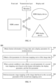
- FIG. 1 shows an example of low dynamic mapping from a high dynamic range of the real world to a display device.
- a larger dynamic range of an image indicates more scene details displayed in the image, more luminance levels and more realistic visual effect.
- one pixel value is generally stored by using one-byte (that is, 8-bit) space.
- one pixel value is stored by using a plurality of bytes of a floating point number, and therefore a high dynamic range for a natural scene can be represented.
- the metadata includes targeted system display actual peak luminance (targeted system display actual peak luminance).
- the metadata includes dynamic metadata and static metadata.
- dynamic metadata for color volume transform or a related standard for static metadata (static metadata).
- static metadata static metadata
- the metadata may be packaged together with an image, for example, include SEI packages of different file formats and different encoding standards, and some package structures related to an HDMI of hardware.
- the display device may further obtain a display parameter M TPL (which may also be referred to as a display luminance parameter) of the display device (that is, an actual terminal device P or a local display device).
- a display parameter M TPL may include maximum display luminance MaxDisplay of the display device and minimum display luminance MinDisplay of the display device, or another parameter. This is not limited in this embodiment of this application.
- the display device may obtain the first parameter of the first tone mapping curve of the image data V based on the metadata M of the image data V and the display parameter M TPL of the display device.
- the first parameter of the first tone mapping curve is obtained based on an average luminance value average_maxrgb, and/or a maximum luminance value MaxSource, and/or a minimum luminance value MinSource of the content of the image data V in the metadata M, and/or the maximum display luminance MaxDisplay of the display device, and/or the minimum display luminance MinDisplay of the display device, and/or the curve parameter M curve ( p1, p2, ...), and/or other data, and may be represented as P1 curve ( X, p1, p2, ).
- X is an input luminance value
- p1, p2, ... are curve parameter values.
- first parameter P1 curve of the first tone mapping curve is not limited in this embodiment of this application.
- data used to generate the first parameter P1 curve or an algorithm used to generate the first parameter P1 curve is not limited in this embodiment of this application.
- the data used to generate the first parameter P1 curve may be metadata, and/or a display parameter of the display device, or may be other preset data.
- the curve parameter M curve includes, for example, parameter values (p, m, a, b, n, K1, K2, or K3) and (TH1[i], TH2[i], TH3[i], or MB0).
- the curve parameter M curve includes, for example, parameter values (p, m, a, b, n, K1, K2, or K3) and (TH1[i], TH2[i], TH3[i], or MB0).
- the first tone mapping curve in this embodiment of this application is an example of the foregoing original tone mapping curve, and includes but is not limited to the tone mapping curves used in Technology 1, Technology 2, Technology 3, Technology 4, and Technology 5.
- the first parameter of the first mapping curve in this application includes but is not limited to parameters related to the tone mapping curves used in Technology 1, Technology 2, Technology 3, Technology 4, and Technology 5.
- input luminance of a tone mapping curve may be linear light, or may be a non-linear value, or may be a value obtained after a linear relationship is normalized (for example, 10000 is used as 1, or maximum luminance of content is used as 1). This is not limited in this embodiment of this application.
- the second parameter R curve of the second tone mapping curve may be obtained based on the first parameter P1 curve , the average luminance value average_maxrgb, and/or the maximum luminance value MaxSource, and/or the minimum luminance value MinSource of the content of the image data V, and/or the maximum display luminance MaxDisplay of the display device, and/or the minimum display luminance MinDisplay of the display device, and/or other data.
- the second parameter R curve may have a form shown in the following formula (9):
- L and L' are normalized electrical signals or optical signals, and Dark, TH3C, TH2D, TH3D, MD1D, MC1D, MB1D, MA1D, MD2D, MC2D, MB2D and MA2D are rational numbers.
- the preset condition is, for example, that when tone mapping is performed on the image data based on the first tone mapping curve, output luminance of a point on the first tone mapping curve is greater than input luminance of the point on the first tone mapping curve.
- the preset condition may be that a parameter p P1 , in the first parameter is greater than a first value Tp.
- the first value Tp is obtained based on a P1 in the first parameter and a preset correspondence between a P1 , and p P1 .
- Tp represents a threshold of the curve parameter p in Technology 3, Technology 4, or Technology 5.
- output luminance at a point on the second tone mapping curve may be greater than input luminance.
- the first parameter P1 curve includes parameters such as a P1 , and p P1 .
- a P1 may be used as Ta, and a corresponding first value Tp is obtained by looking up a table Tpa (Tp, Ta).
- the table Tpa (Tp, Ta) is an example of the preset correspondence between a P1 , and p P1 .
- Ta represents a threshold of the curve parameter a in Technology 3, Technology 4, or Technology 5.
- p P1 in the first parameter P1 curve may be replaced with the first value Tp obtained through table lookup.
- a first parameter P1 curve obtained after replacement may be the foregoing second parameter R curve .
- the preset condition may be that a parameter a P1 in the first parameter is greater than a second value Ta.
- the second value Ta is obtained based on p P1 , in the first parameter and a preset correspondence between a P1 , and p P1 .
- output luminance at a point on the second tone mapping curve may be greater than input luminance.
- the first parameter P1 curve includes parameters such as a P1 , and p P1 .
- p P1 may be used as Tp
- a corresponding second value Ta is obtained by looking up a table Tpa (Tp, Ta).
- the table Tpa (Tp, Ta) is an example of the preset correspondence between a P1 , and p P1 .
- a P1 is greater than Ta, the preset condition is met.
- a P1 in the first parameter P1 curve may be replaced with the second value Ta obtained through table lookup.
- the first parameter obtained after replacement may be the second parameter R curve .
- Table Tpa (Tp, Ta) is a preset rational number combination, for example, (3.5, 0.879) and (4.5, 0.777). It should be noted that, for a value that does not appear in the table, the value may be generated by using a linear difference, an adjacent value, a weighted average value of adjacent values, or the like.
- a specific form of the table Tpa (Tp, Ta) is not limited in this embodiment of this application.
- the table Tpa (Tp, Ta) may alternatively be represented as a function relationship between Tp and Ta.
- the second parameter further includes a linear spline curve parameter.
- the linear spline curve parameter includes a maximum value TH3C (which may also be referred to as first maximum input luminance TH3C) of a luminance value of a range pixel of a linear spline (which may be denoted as a first linear spline) in the second tone mapping curve, and a slope Dark of the first linear spline.
- the first linear spline is, for example, a tone mapping curve whose input luminance is less than TH3C in the foregoing formula (9), that is, Dark ⁇ L, L ⁇ TH3C.
- L ⁇ TH3C is range pixel of the first linear spline.
- the display device may obtain a maximum value TH3C0 (which may also be referred to as initial first maximum input luminance TH3C0) of a luminance value of an initial range pixel of the first linear spline and an initial slope Dark0, then determine the first maximum input luminance TH3C based on the initial first maximum input luminance TH3C0, and determine the slope Dark based on the initial slope Dark0.
- a maximum value TH3C0 (which may also be referred to as initial first maximum input luminance TH3C0) of a luminance value of an initial range pixel of the first linear spline and an initial slope Dark0
- the display device may determine the initial first maximum input luminance TH3C0 based on the first parameter P1 curve .
- the first tone mapping curve has a linear spline (which may be denoted as a second linear spline, for example, Technology 2, Technology 4, or Technology 5)
- the initial first maximum input luminance TH3C0 may be determined as a maximum value of a luminance value of a range pixel of the second linear spline.
- the display device determines the initial first maximum input luminance TH3C0 based on a preset value.
- the preset value may be a boundary of dark vision and bright vision, that is, luminance in which responses of a cone cell and a rod cell of a human eye increase and decrease, for example, 1 nit.
- the display device determines the initial first maximum input luminance TH3C0 based on the metadata M of the image data V.
- the metadata M includes feature data of a quantity of dark region pixels in a histogram, for example, a feature luminance location of the quantity of dark region pixels in the histogram or luminance in which a quantity/an accumulated quantity of pixels from dark to bright in the dark region pixels significantly changes, or a percentage of a quantity of pixels accumulated from 0 to feature luminance in total pixels being greater than a preset percentage.
- the display device may determine the initial slope Dark0 based on the first parameter P1 curve .
- the initial slope Dark0 may be determined as a slope of the second linear spline, for example, MB0 in Technology 4 or Technology 5.
- the display device may determine the initial slope Dark0 based on a ratio of a fourth value to the first maximum input luminance TH3C.
- the fourth value is an output value of the first tone mapping curve at the first maximum input luminance TH3C.
- the initial slope Dark0 may be represented as (Vdark/TH3C).
- the display device may determine the initial slope Dark0 based on a slope value of a preset input value of the first tone mapping curve between 0 and the first maximum input luminance TH3C.
- the initial slope Dark0 may be an average value, a maximum value, or an intermediate value of slope values between 0 and the first maximum input luminance TH3C. This is not limited in this application.
- the following describes two methods for obtaining the first maximum input luminance TH3C and the slope Dark of the second target tone mapping curve based on the initial first maximum input luminance TH3C0 and the initial slope Dark0 provided in this embodiment of this application.
- N1 and N2 are rational numbers greater than 0
- H(L) is a tone mapping curve
- G(L) is an inverse function of H(L).
- the first maximum input luminance TH3C and the slope Dark may be determined based on the following formulas (12) and (13), that is, the first initial maximum input luminance TH3C0, the first maximum input luminance TH3C, the initial slope Dark0, and the slope Dark satisfy the following formulas (12) and (13):
- WA MaxDisplay max_lum ⁇ MaxDisplay G MaxDisplay 1 ⁇ MaxDisplay G MaxDisplay
- WA MaxDisplay Max_lum ⁇ H Max_lum Max_lum 1 ⁇ H Max_lum Max_lum .
- MaxLum is an adjustment value of the maximum luminance MaxSource of the image data
- H(L) is a tone mapping curve function
- G(L) is an inverse function of H(L). It should be noted that a manner of adjusting from MaxSource to MaxLum is not limited in this embodiment of this application.
- an inverse function G(L) of the tone mapping curve is shown in a formula (15-1):
- G L K 3 ⁇ L ⁇ b a 1 m p ⁇ K 1 ⁇ p ⁇ K 2 ⁇ L ⁇ b a 1 m 1 n
- a tone mapping curve corresponding to the first cubic spline may be a tone mapping curve whose input luminance range is greater than or equal to TH3C and less than TH2D in the foregoing formula (9), that is, MD 1 D ⁇ ( L - TH 1 D ) 3 + MC 1 D ⁇ ( L - TH 1 D ) 2 + MB 1 D ⁇ ( L - TH 1 D ) + MA 1 D,TH 1 D ⁇ L ⁇ TH 2 D, where TH 1 D ⁇ L ⁇ TH 2 D is the first range pixel.
- the second parameter R curve further includes a maximum value TH3D of a luminance value of a second range pixel of a second cubic spline on the second tone mapping curve, and the maximum value TH3D may also be referred to as a third maximum input luminance TH3D.
- the minimum value of the luminance value of the second range pixel may be TH2D.
- a tone mapping curve corresponding to the second cubic spline may be a tone mapping curve whose input luminance range is greater than or equal to TH2D and less than TH3D in the foregoing formula (9), that is, MD 2 D ⁇ ( L - TH 2 D ) 3 + MC 2 D ⁇ ( L - TH 2 D ) 2 + MB 2 D ⁇ ( L - TH 2 D ) + MA 2 D, TH 2 D ⁇ L ⁇ TH 3 D, where TH 2 D ⁇ L ⁇ TH 3 D is the second range pixel.
- the display device may determine the third maximum input luminance TH3D based on the maximum value TH1D of the luminance value of the first range pixel and the second maximum input luminance TH2D.
- the following describes three methods for determining the second maximum input luminance TH2D and the third maximum input luminance TH3D provided in this embodiment of this application.
- the display device may determine the second maximum input luminance TH2D based on the maximum value TH1D of the luminance value of the first range pixel and TH1[0], TH2[0], and TH3[0] in the first parameter (or parameters TH1[0], TH2[0], and TH3[0] included in the metadata M).
- the display device may determine TH2D and TH3D based on TH1D and the preset value.
- TH2D and TH3D may respectively satisfy the following formula (18) and formula (19):
- output values of the first linear spline and the first cubic spline on the second tone mapping curve at TH1D are the same, and first-order derivatives of the first linear spline and the first cubic spline on the second tone mapping curve at TH1D are the same, that is, the second tone mapping curve is consecutive at TH1D.
- the maximum value of the luminance value of the second range pixel of the second cubic spline is the same as the maximum value TH2D of the luminance value of the first range pixel of the first cubic spline, that is, the second maximum input luminance TH2D.
- Output values of the second cubic spline and the first cubic spline at TH2D are the same.
- the first range pixel of the first cubic spline on the second tone mapping curve can be consecutive with the second range pixel of the second cubic spline.
- first-order derivatives of the second cubic spline and the first cubic spline at TH2D are the same, that is, the second tone mapping curve is consecutive at TH2D.
- the second parameter further includes a curve parameter of a tone mapping subfunction of the second tone mapping curve.
- a minimum value of a luminance value of a third range pixel of the tone mapping subfunction is the same as the maximum value TH3D of the luminance value of the second range pixel of the second cubic spline, that is, the third maximum input luminance TH3D.
- the second range pixel of the second cubic spline on the second tone mapping curve can be consecutive with second range pixel corresponding to the tone mapping subfunction.
- output values of the second cubic spline and the tone mapping subfunction at TH3D are the same, and first derivatives of the second cubic spline and the tone mapping subfunction at TH3D are the same, that is, the second tone mapping curve is consecutive at TH3D.
- values of the foregoing two segments of cubic splines (that is, the first cubic spline and the second cubic spline) at TH2D may be obtained according to a preset policy.
- values of the two segments of cubic splines at TH2D each may be a value of a middle point of a connection line between two points whose input luminance is TH1D and TH3D and that are on the second tone mapping curve.
- the cubic spline curve in the second tone mapping curve can smoothly connect a linear spline curve to a basic curve, and on the other hand, the cubic spline curve can help control a gain of a part adjacent to the straight line part.
- a mapping relationship between normalized HDR/SDR source data and normalized HDR/SDR display data may be obtained based on the foregoing formula (9). For example, based on a maximum display capability and a minimum display capability (for example, 0) of the display device, a mapping value L' may be reversely normalized to a value between the maximum display capability and the minimum display capability of the display device. It should be noted that the foregoing reverse normalization calculation may be a non-linear space of PQ, or may be a linear space of normalization 0 to 1. In addition, reverse normalization may be 0-10000 nits, or may be 0.0001-100000 nits, or the like. A reverse normalization range and a reverse normalization process of HDR/SDR mapping data L' are not limited in this embodiment of this application.
- subsequent display adaptation processing not only includes tone mapping (tone mapping), but also may be further adjusted before display to adjust saturation processing, color gamut transformation processing, denoising processing, sharpening processing, and/or the like. This is not limited in this embodiment of this application.
- the maximum display capability of the display device may be obtained based on a parameter of the device or information about a manufacturer.
- the minimum display capability of the display device is usually 0 nits, or may be 1 nit. This is not limited in this embodiment of this application.
- a parameter of a tone mapping curve is further adjusted, so that output luminance of a tone mapping curve corresponding to an adjusted curve parameter is not greater than input luminance of the tone mapping curve.
- the linear spline curve parameter (which may be denoted as a first linear spline curve parameter) in the second parameter may include the slope of the first linear spline on the second tone mapping curve (for example, may be represented as MB [0] [0]) and the maximum value (for example, may be represented as TH3 [0]) of the luminance value of the range pixel of the first linear spline).
- the linear spline curve parameter (which may be denoted as a first linear spline curve parameter) in the second parameter may include the slope of the first linear spline on the second tone mapping curve (for example, may be represented as MB[0][0]), the maximum value (for example, may be represented as TH3 [0]) of the luminance value of the range pixel of the first linear spline), and an intersection point base_offset of the first linear spline and a vertical axis.
- the linear spline curve parameter (which may be denoted as a second linear spline curve parameter) included in the first parameter may include a slope (for example, may be represented as MB_mid[0] [0]) of the second linear spline on the first tone mapping curve and/or the maximum value (for example, may be represented as TH3_mid[0]) of the luminance value of the range pixel of the second linear spline.
- an implementation of obtaining, based on the first parameter, the display parameter, and the feature information, the second parameter of the second tone mapping curve when the preset condition is met may be: adjusting the curve parameters MB_mid[0][0] and TH3_mid[0] based on the maximum display luminance MaxDisplay and the maximum luminance correction value max_lum, to obtain the curve parameters MB[0][0] and TH3[0].
- Tm_ap may be obtained based on a preset mapping relationship between m_p_T and m_a_T, for example, by looking up a table (m_p_T, m_a_T), where m_p corresponds to a tone mapping curve parameter p, and a preset value Tm_ap(m_p) of m_a obtained based on m_p is m_a_T.
- input may be maximum display luminance MaxDisplay (a value of a PQ domain) in a display luminance range of the display device, a maximum luminance correction value max_lum of a to-be-processed frame, targeted_system_display_maximum_luminance in metadata (if targeted_system_display_maximum_luminance does not exist in the metadata, the targeted_system_display_maximum_luminance is equal to MaxDisplay), an original linear spline curve (that is, a linear spline curve in the first tone mapping curve) parameter MB[0][0] or TH3[0], and a color signal mapping curve parameter Ptone_mapping, including m_p, m_m, m_n, m_a, m_b, k1, k2, and k3.
- Output may be a linear spline curve (that is, a linear spline curve (that is, a linear spline curve (that is, a linear splin
- N1 and N2 are rational numbers greater than 0, and G(L) is an inverse function of a mapping curve parameter T curve .
- MaxLum is the maximum luminance correction value (an adjustment value of MaxSource)
- G (L) is an inverse function of a mapping curve parameter T curve .
- L is an input signal
- G(L) is an inverse function of a function H(L) corresponding to a tone mapping curve
- m_a, m_b, m_m, m_n, k1, k2, and k3 are curve parameters
- G(L, m_a_T) indicates a G(L) value corresponding to an input variable L when a value of a parameter M_a of G(L) is m_a_T
- H(L, m_a_T) is similar.
- N1 and N2 are rational numbers, for example, default values of N1 and N2 may be 0.
- max(a, b) indicates calculating a larger value of a and b
- min(a, b) indicates calculating a smaller value of a and b.
- k1 and k2 are not 0 at the same time, and K3 is not 0.
- the first parameter may include the second linear spline curve parameter.
- the second linear spline curve parameter includes the slope MB_mid[0][0] of the second linear spline on the first tone mapping curve and/or the maximum value TH3_mid[0] of the luminance value of the range pixel of the second linear spline and/or an intersection point base_offset_mid of the first linear spline and a vertical coordinate axis.
- the display parameter includes the maximum display luminance MaxDisplay of the terminal device.
- the feature information includes the maximum luminance correction value max_lum of the image data.
- That the second parameter of the second tone mapping curve is obtained based on the first parameter, the display parameter, and the feature information includes: adjusting the curve parameters MB_mid[0][0], TH3_mid[0], and/or base_offset_mid based on the maximum display luminance MaxDisplay and the maximum luminance correction value max_lum, to obtain the curve parameters MB[0] [0], TH3[0], and/or base_offset.
- L is an input signal
- G(L) is an inverse function of a function H(L) corresponding to a tone mapping curve
- m_a, m_b, m_m, m_n, k1, k2, and k3 are curve parameters
- G(L, m_a_T) indicates a G(L) value corresponding to an input variable L when a value of a parameter M_a of G(L) is m_a_T
- N1, N2, and N3 are rational numbers
- max(a, b) indicates calculating a larger value of a and b
- min(a, b) indicates calculating a smaller value of a and b
- the second parameter includes a cubic spline curve parameter.
- the cubic spline curve parameter includes interpolation point values TH1[1], TH2[1], and TH3[1] of a cubic spline on the second tone mapping curve.
- TH1[1] indicates a minimum value of a luminance value of first range pixel of the cubic spline.
- TH2[1] indicates a maximum value of the luminance value of the first range pixel of the cubic spline and a minimum value of a luminance value of second range pixel of the cubic spline.
- TH3[1] indicates a maximum value of the luminance value of the second range pixel of the cubic spline.
- TH1 [1] may be an example of TH1D
- TH2[1] may be an example of TH2D
- TH3[1] may be an example of TH3D.
- the interpolation point values TH1[1], TH2[1], and TH3[1] of the cubic spline may be calculated based on the second linear spline curve parameter TH3[0] in the first parameter and preset offset values of correlation values for calculating the interpolation point values TH1[1], TH2[1], and TH3[1] of the cubic spline.
- the interpolation point values TH1[1], TH2[1], and TH3[1] of the cubic spline may be calculated based on the second linear spline curve parameter TH3[0] in the first parameter and correlation values for calculating the interpolation point values TH1[1], TH2[1], and TH3[1] of the cubic spline.
- TH1[1], TH2[1], and TH3[1] satisfy the following formulas (35) to (37):
- TH 1 1 3 Spline _ TH i 0 w
- TH 2 1 3 Spline _ TH i 0 w + 3 Spline _ TH _ Delta 1 i 1 w and
- TH 3 1 3 Spline_TH i 0 w + 3 Spline_TH_Delta 1 i 1 w + 3 Spline_TH_Delta 1 i 2 w
- 3Spline_TH_Deltal[i][1][w] are the correlation values that are used for calculating the interpolation point values TH1[1], TH2[1], and TH3[1] of the cubic spline and that are extracted from the metadata.
- coordinates corresponding to TH1[1], TH2[1], and TH3[1] in the second tone mapping curve may be obtained, for example, may be respectively represented as VA1, VA2, and VA3.
- AY coordinate of the linear spline on the second tone mapping curve at TH3[0] is the same as a Y coordinate of the cubic spline on the second tone mapping curve at TH1[1]
- a first-order derivative of the linear spline at TH3[0] is the same as a first-order derivative of the cubic spline at TH1[1].
- a Y coordinate of the first cubic spline on the second tone mapping curve at TH2[1] is the same as a Y coordinate of the second cubic spline on the second tone mapping curve at TH2[1]
- a first-order derivative of the first cubic spline at TH2[1] is the same as a first-order derivative of the second cubic spline at TH2[1].
- a Y coordinate of the second cubic spline on the second tone mapping curve at TH3[1] is the same as a Y coordinate of a third tone mapping function on the second tone mapping curve at TH3[1]
- a first-order derivative of the second cubic spline at TH3[1] is the same as a first-order derivative of the third tone mapping function at TH3[1].
- Parameters such as MC[0][1], MD[0][1], MB[1][1], MC[1][1], and MD[1][1] in the second parameter may be obtained through the foregoing calculation with reference to another condition.
- a parameter of the first tone mapping curve is further adjusted, so that output luminance of a point on a tone mapping curve (that is, the second tone mapping curve) corresponding to an adjusted curve parameter (that is, the second parameter) is not greater than corresponding input luminance of the point.
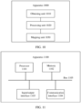
- FIG. 10 is a schematic block diagram of a dynamic range mapping apparatus 1000 according to an embodiment of this application.
- the apparatus 1000 includes an obtaining unit 1010, a processing unit 1020, and a mapping unit 1030.
- the obtaining unit 1010 is configured to obtain a display parameter of a terminal device.
- the obtaining unit 1010 is further configured to obtain feature information of image data.
- the obtaining unit 1010 is further configured to obtain a first parameter of a first tone mapping curve of the image data.
- the processing unit 1020 is configured to: when a preset condition is met, obtain a second parameter of a second tone mapping curve based on the first parameter, the display parameter of the terminal device, and the feature information of the image data. Output luminance at a first point on the second tone mapping curve is not greater than input luminance at the first point on the second tone mapping curve.
- the mapping unit 1030 is configured to perform dynamic range mapping on the image data based on the second parameter of the second tone mapping curve.
- the preset condition is met when any one of the following conditions is met:
- output luminance at a second point on the first tone mapping curve is greater than input luminance at the second point on the first tone mapping curve.
- a parameter p P1 , in the first parameter is greater than a first value Tp.
- the first value Tp is obtained based on a P1 in the first parameter and a preset correspondence between a P1 , and p P1 .
- a parameter a P1 in the first parameter is greater than a second value Ta.
- the second value Ta is obtained based on p P1 in the first parameter and a preset correspondence between a P1 , and p P1 .
- a product of a parameter a P1 and a parameter p P1 , in the first parameter is greater than a third value Tap.
- the third value Tap is a preset rational number.
- the second parameter includes a first linear spline curve parameter.
- the first linear spline curve parameter includes a slope MB[0][0] of a first linear spline on the second tone mapping curve or a maximum value TH3[0] of a luminance value of a range pixel of the first linear spline.
- the first parameter includes a second linear spline curve parameter.
- the second linear spline curve parameter includes a slope MB_mid[0][0] of a second linear spline on the first tone mapping curve and a maximum value TH3_mid[0] of a luminance value of a range pixel of the second linear spline.
- the display parameter includes maximum display luminance MaxDisplay of the terminal device.
- the feature information includes a maximum luminance correction value max_lum of the image data.
- the processing unit 1020 is specifically configured to: adjust the curve parameters MB_mid[0][0] and TH3_mid[0] based on the maximum display luminance MaxDisplay and the maximum luminance correction value max_lum to obtain the curve parameters MB[0][0] and TH3[0].
- L is an input signal
- G(L) is an inverse function of a function H(L) corresponding to a tone mapping curve
- m_a, m_b, m_m, m_n, k1, k2, and k3 are curve parameters
- G(L, m_a_T) indicates a G(L) value corresponding to an input variable L when a value of a parameter M_a of G(L) is m_a_T
- H(L, m_a_T) is similar
- N1 and N2 are rational numbers
- max(a, b) indicates calculating a larger value of a and b
- min(a, b) indicates calculating a smaller value of a and b
- the second parameter includes a cubic spline curve parameter.
- the cubic spline curve parameter includes interpolation point values TH1[1], TH2[1], and TH3[1] of a cubic spline on the second tone mapping curve.
- TH1[1] indicates a minimum value of a luminance value of first range pixel of the cubic spline.
- TH2[1] indicates a maximum value of the luminance value of the first range pixel of the cubic spline and a minimum value of a luminance value of second range pixel of the cubic spline.
- TH3[1] indicates a maximum value of the luminance value of the second range pixel of the cubic spline.
- B, C, and D are preset values of correlation values for calculating the interpolation point values TH1[1], TH2[1], and TH3[1] of the cubic spline.
- B is a preset offset value corresponding to a luminance value of a dark-bright transition region pixel.
- C and D are preset weighting coefficients corresponding to a luminance value of a bright region pixel.
- 3Spline_TH_Delta1[i][2][w] are the correlation values that are used for calculating the interpolation point values TH1[1], TH2[1], and TH3[1] and that are extracted from metadata.
- a Y coordinate of a linear spline on the second tone mapping curve at TH3[0] is the same as a Y coordinate of the cubic spline on the second tone mapping curve at TH1[1]
- a first-order derivative of the linear spline at TH3[0] is the same as a first-order derivative of the cubic spline at TH1[1].
- a Y coordinate of a first cubic spline on the second tone mapping curve at TH2[1] is the same as a Y coordinate of a second cubic spline on the second tone mapping curve at TH2[1]
- a first-order derivative of the first cubic spline at TH2[1] is the same as a first-order derivative of the second cubic spline at TH2[1].
- a Y coordinate of the second cubic spline on the second tone mapping curve at TH3[1] is the same as a Y coordinate of a third tone mapping function on the second tone mapping curve at TH3[1]
- a first-order derivative of the second cubic spline at TH3[1] is the same as a first-order derivative of the third tone mapping function at TH3[1].
- the obtaining unit 1010 is specifically configured to:
- FIG. 11 is a schematic diagram of a hardware structure of a dynamic range mapping apparatus 1100 according to an embodiment of this application.
- the apparatus 1100 shown in FIG. 11 may be considered as a computer device.
- the apparatus 1100 may be used as an implementation of the dynamic range mapping apparatus in embodiments of this application, or may be used as an implementation of the dynamic range mapping method in embodiments of this application.
- the apparatus 1100 includes a processor 1101, a memory 1102, an input/output interface 1103, and a bus 1105, and may further include a communication interface 1104.
- the processor 1101, the memory 1102, the input/output interface 1103, and the communication interface 1104 implement a communication connection to each other by using the bus 1105.
- the processor 1101 may be a general-purpose central processing unit (central processing unit, CPU), a microprocessor, an application-specific integrated circuit (application-specific integrated circuit, ASIC), or one or more integrated circuits.
- the processor 1101 is configured to execute a related program to implement functions that need to be executed by modules in the media data processing apparatus in embodiments of this application, or to perform the media data processing method in the method embodiments of this application.
- the processor 1101 may be an integrated circuit chip and has a signal processing capability. In an implementation process, the steps in the foregoing method may be completed by using an integrated logic circuit of hardware in the processor 1101 or an instruction in a form of software.
- the processor 1101 may be a general-purpose processor, a digital signal processor (digital signal processor, DSP), an application-specific integrated circuit (ASIC), a field programmable gate array (field programmable gate array, FPGA), another programmable logic device, a discrete gate, a transistor logic device, or a discrete hardware component.
- the processor may implement or perform the method, the steps, and the logical block diagrams that are disclosed in embodiments of this application.
- the general-purpose processor may be a microprocessor, or the processor may be any conventional processor or the like. The steps of the method disclosed with reference to embodiments of this application may be directly performed and completed by a hardware decoding processor, or may be performed and completed by using a combination of hardware and software modules in the decoding processor.
- a software module may be located in a mature storage medium in the art, such as a random access memory, a flash memory, a read-only memory, a programmable read-only memory, an electrically erasable programmable memory, or a register.
- the storage medium is located in the memory 1102.
- the processor 1101 reads information in the memory 1102, and completes, in combination with hardware of the processor 1101, a function that needs to be executed by a module included in the media data processing apparatus in embodiments of this application, or performs the media data processing method in the method embodiments of this application.
- the memory 1102 may be a read-only memory (read-only memory, ROM), a static storage device, a dynamic storage device, or a random access memory (random access memory, RAM).
- the memory 1102 may store an operating system and another application program.
- program code used to implement the technical solutions provided in embodiments of this application is stored in the memory 1102, and the processor 1101 performs operations that need to be performed by the modules that are included in the media data processing apparatus, or performs the media data processing method provided in the method embodiments of this application.
- the input/output interface 1103 is configured to receive input data and information, and output data such as an operation result.
- the communication interface 1104 uses a transceiver apparatus, for example, but not limited to, a transceiver, to implement communication between the apparatus 1100 and another device or a communication network.
- the communication interface 1104 may be used as an obtaining module or a sending module in the processing apparatus.
- the bus 1105 may include a path for transmitting information between components (for example, the processor 1101, the memory 1102, the input/output interface 1103, and the communication interface 1104) of the apparatus 1100.
- the apparatus 1100 further includes another device required for implementing normal running, for example, may further include a display that is configured to display to-be-played video data.
- the apparatus 1100 may further include hardware components for implementing other additional functions.
- the apparatus 1100 may alternatively include only components required for implementing this embodiment of this application, but not necessarily include all the components shown in FIG. 11 .
- An embodiment of this application further provides a computer-readable storage medium.
- the computer-readable storage medium stores instructions, and when the instructions are run on a computer, the computer is enabled to perform the foregoing dynamic range mapping method.
- An embodiment of this application further provides a computer program product including instructions.
- the computer program product runs on a computer, the computer is enabled to perform the foregoing dynamic range mapping method.
- the disclosed system, apparatus, and method may be implemented in another manner.
- the described apparatus embodiments are merely examples.
- division into the units is merely logical function division and may be other division in actual implementation.
- a plurality of units or components may be combined or integrated into another system, or some features may be ignored or not performed.
- the displayed or discussed mutual couplings or direct couplings or communication connections may be implemented by using some interfaces.
- the indirect couplings or communication connections between the apparatuses or units may be implemented in electronic, mechanical, or other forms.
- the units described as separate parts may or may not be physically separate, and parts displayed as units may or may not be physical units, and may be located in one location, or may be distributed on a plurality of network units. Some or all of the units may be selected based on actual requirements to achieve the objectives of the solutions of embodiments.
- functional units in embodiments of this application may be integrated into one processing unit, or each of the units may exist alone physically, or two or more units are integrated into one unit.
- the functions When the functions are implemented in a form of a software functional unit and sold or used as an independent product, the functions may be stored in a computer-readable storage medium. Based on such understanding, the technical solutions of this application essentially, or the part contributing to the conventional technology, or some of the technical solutions may be implemented in a form of a software product.
- the computer software product is stored in a storage medium, and includes several instructions for indicating a computer device (which may be a personal computer, a server, a network device or the like) to perform all or some of the steps of the methods described in embodiments of this application.
- the foregoing storage medium includes any medium that can store program code, such as a USB flash drive, a removable hard disk, a read-only memory (read-only memory, ROM), a random access memory (random access memory, RAM), a magnetic disk, or an optical disc.
- program code such as a USB flash drive, a removable hard disk, a read-only memory (read-only memory, ROM), a random access memory (random access memory, RAM), a magnetic disk, or an optical disc.
Landscapes
- Engineering & Computer Science (AREA)
- Physics & Mathematics (AREA)
- General Physics & Mathematics (AREA)
- Theoretical Computer Science (AREA)
- Multimedia (AREA)
- Signal Processing (AREA)
- Computer Hardware Design (AREA)
- Software Systems (AREA)
- Image Processing (AREA)
- Facsimile Image Signal Circuits (AREA)
- Analysing Materials By The Use Of Radiation (AREA)
Claims (7)
- Dynamikbereichsabbildungsverfahren (900), das Folgendes umfasst:Erhalten (910) eines Anzeigeparameters einer Endgerätevorrichtung;Erhalten (910) von Merkmalsinformationen von Bilddaten;Erhalten (920) eines ersten Parameters einer ersten Tonabbildungskurve der Bilddaten, wobei der erste Parameter einen Parameter pP1 und einen Parameter aP1 beinhaltet, wobei ein Wert Ta basierend auf dem Parameter aP1 und einer voreingestellten Entsprechung zwischen dem Parameter aP1 und dem Parameter pP1 erhalten wird;wenn der Parameter aP1 in dem ersten Parameter größer als der Wert Ta ist, Erhalten (930) eines zweiten Parameters einer zweiten Tonabbildungskurve basierend auf dem ersten Parameter, dem Anzeigeparameter der Endgerätevorrichtung und den Merkmalsinformationen der Bilddaten, sodass eine Ausgangsleuchtdichte der zweiten Tonabbildungskurve nicht größer als eine Eingangsleuchtdichte auf der zweiten Tonabbildungskurve ist; undDurchführen (940) einer Dynamikbereichsabbildung an den Bilddaten basierend auf dem zweiten Parameter der zweiten Tonabbildungskurve;wobei der zweite Parameter einen Kurvenparameter eines ersten linearen Spline umfasst und der Kurvenparameter eines ersten linearen Spline eine Steigung MB[0][0] eines ersten linearen Spline auf der zweiten Tonabbildungskurve und/oder einen maximalen Wert TH3[0] eines Leuchtdichtewerts eines Bereichspixels des ersten linearen Spline und/oder einen Schnittpunkt base_offset des ersten linearen Spline und einer vertikalen Koordinatenachse umfasst;wobei der erste Parameter einen Kurvenparameter eines zweiten linearen Spline umfasst, der Kurvenparameter eines zweiten linearen Spline eine Steigung MB_mid[0][0] eines zweiten linearen Spline auf der ersten Tonabbildungskurve und/oder einen maximalen Wert TH3_mid[0] eines Leuchtdichtewerts eines Bereichspixels des zweiten linearen Spline umfasst, der Anzeigeparameter eine maximale Anzeigeleuchtdichte MaxDisplay der Endgerätevorrichtung umfasst und die Merkmalsinformationen einen Korrekturwert max_lum der maximalen Leuchtdichte der Bilddaten umfassen; unddas Erhalten eines zweiten Parameters einer zweiten Tonabbildungskurve basierend auf dem ersten Parameter, dem Anzeigeparameter und den Merkmalsinformationen Folgendes umfasst:Anpassen der Kurvenparameter MB_mid[0][0] und TH3_mid[0] basierend auf der maximalen Anzeigeleuchtdichte MaxDisplay und dem Korrekturwert max_lum der maximalen Leuchtdichte, um die Kurvenparameter MB[0][0] und TH3[0] zu erhalten, wobei die Kurvenparameter MB_mid[0][0] und TH3_mid[0] und die Kurvenparameter MB[0][0] and TH3[0] die folgenden Formeln erfüllen:

 wobei
wobei

 L ein Eingangssignal ist, G(L) eine Umkehrfunktion einer Funktion H(L), die einer Tonabbildungskurve entspricht, ist, m_a, m_b, m_m, m_n, k1, k2 und k3 Kurvenparameter sind, G(L, m_a_T) einen G(L)-Wert angibt, der einer Eingangsvariablen L entspricht, wenn ein Wert eines Parameters M_a von G(L) m_a_T ist, N1 und N2 rationale Zahlen sind, max(a, b) das Berechnen eines größeren Werts von a und b angibt, min(a, b) das Berechnen eines kleineren Werts von a und b angibt und H(L) Folgendes ist:
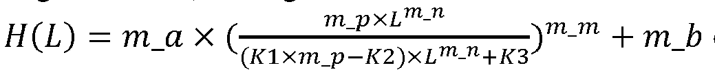

- Verfahren (900) nach Anspruch 1, wobei der zweite Parameter einen Kurvenparameter eines kubischen Spline umfasst und der Kurvenparameter eines kubischen Spline Interpolationspunktwerte TH1[1], TH2[1] und TH3[1] eines kubischen Spline auf der zweiten Tonabbildungskurve umfasst, wobei TH1[1] einen minimalen Wert eines Leuchtdichtewerts eines ersten Bereichspixels des kubischen Spline angibt, TH2[1] einen maximalen Wert des Leuchtdichtewerts des ersten Bereichspixels des kubischen Spline und einen minimalen Wert eines Leuchtdichtewerts eines zweiten Bereichspixels des kubischen Spline angibt und TH3[1] einen maximalen Wert des Leuchtdichtewerts des zweiten Bereichspixels des kubischen Spline angibt.
- Verfahren (900) nach einem der Ansprüche 1 bis 2, wobei das Erhalten eines ersten Parameters einer ersten Tonabbildungskurve der Bilddaten Folgendes umfasst:Erhalten der Metadaten der Bilddaten; undBestimmen des ersten Parameters der ersten Tonabbildungskurve basierend auf den Metadaten und dem Anzeigeparameter.
- Verfahren (900) nach einem der Ansprüche 1 bis 3, wobei der erste Parameter den Kurvenparameter eines zweiten linearen Spline umfasst, der Kurvenparameter eines zweiten linearen Spline die Steigung MB_mid[0][0] des zweiten linearen Spline auf der ersten Tonabbildungskurve und/oder den maximalen Wert TH3_mid[0] des Leuchtdichtewerts des Bereichspixels des zweiten linearen Spline und/oder einen Schnittpunkt base_offset_mid des ersten linearen Spline und der vertikalen Koordinatenachse umfasst, der Anzeigeparameter die maximale Anzeigeleuchtdichte MaxDisplay der Endgerätevorrichtung umfasst und die Merkmalsinformationen den Korrekturwert max_lum der maximalen Leuchtdichte der Bilddaten umfasst; und das Erhalten eines zweiten Parameters einer zweiten Tonabbildungskurve basierend auf dem ersten Parameter, dem Anzeigeparameter und den Merkmalsinformationen Folgendes umfasst:
Anpassen der Kurvenparameter MB_mid[0][0], TH3_mid[0] und/oder base_offset_mid basierend auf der maximalen Anzeigeleuchtdichte MaxDisplay und dem Korrekturwert der maximalen Leuchtdichte max_lum, um die Kurvenparameter MB[0][0], TH3[0] und/oder base_offset zu erhalten. - Dynamikbereichsabbildungsvorrichtung (1000, 1100), die Folgendes umfasst:eine Erhalteeinheit (1010), ausgelegt zum Erhalten (910) eines Anzeigeparameters einer Endgerätevorrichtung, wobeidie Erhalteeinheit (1010) ferner ausgelegt ist zum Erhalten (910) von Merkmalsinformationen von Bilddaten; unddie Erhalteeinheit (1010) ferner ausgelegt ist zum Erhalten (920) eines ersten Parameters einer ersten Tonabbildungskurve der Bilddaten, wobei der erste Parameter einen Parameter aP1 und einen Parameter pP1 beinhaltet, wobei ein Wert Ta basierend auf dem Parameter aP1 und einer voreingestellten Entsprechung zwischen dem Parameter aP1 und dem Parameter pP1 erhalten wird;eine Verarbeitungseinheit (1020), die zu Folgendem ausgelegt ist: wenn der Parameter aP1 in dem ersten Parameter größer als der Wert Ta ist, Erhalten (930) eines zweiten Parameters einer zweiten Tonabbildungskurve basierend auf dem ersten Parameter, dem Anzeigeparameter der Endgerätevorrichtung und den Merkmalsinformationen der Bilddaten, sodass eine Ausgangsleuchtdichte der zweiten Tonabbildungskurve nicht größer als eine Eingangsleuchtdichte auf der zweiten Tonabbildungskurve ist; undeine Abbildungseinheit (1030), ausgelegt zum Durchführen (940) einer Dynamikbereichsabbildung an den Bilddaten basierend auf dem zweiten Parameter der zweiten Tonabbildungskurve;wobei der zweite Parameter einen Kurvenparameter eines ersten linearen Spline umfasst und der Kurvenparameter eines ersten linearen Spline eine Steigung MB[0][0] eines ersten linearen Spline auf der zweiten Tonabbildungskurve und/oder einen maximalen Wert TH3[0] eines Leuchtdichtewerts eines Bereichspixels des ersten linearen Spline und/oder einen Schnittpunkt base_offset des ersten linearen Spline und einer vertikalen Koordinatenachse umfasst;wobei der erste Parameter einen Kurvenparameter eines zweiten linearen Spline umfasst, der Kurvenparameter eines zweiten linearen Spline eine Steigung MB_mid[0][0] eines zweiten linearen Spline auf der ersten Tonabbildungskurve und/oder einen maximalen Wert TH3_mid[0] eines Leuchtdichtewerts eines Bereichspixels des zweiten linearen Spline umfasst, der Anzeigeparameter eine maximale Anzeigeleuchtdichte MaxDisplay der Endgerätevorrichtung umfasst und die Merkmalsinformationen einen Korrekturwert max_lum der maximalen Leuchtdichte der Bilddaten umfassen; unddie Verarbeitungseinheit (1020) insbesondere zu Folgendem ausgelegt ist:Anpassen der Kurvenparameter MB_mid[0][0] und TH3_mid[0] basierend auf der maximalen Anzeigeleuchtdichte MaxDisplay und dem Korrekturwert max_lum der maximalen Leuchtdichte, um die Kurvenparameter MB[0][0] und TH3[0] zu erhalten; undwobei die Kurvenparameter MB_mid[0][0] und TH3_mid[0] und die Kurvenparameter MB[0][0] and TH3[0] die folgenden Formeln erfüllen:

 wobei
wobei

 L ein Eingangssignal ist, G(L) eine Umkehrfunktion einer Funktion H(L), die einer Tonabbildungskurve entspricht, ist, m_a, m_b, m_m, m_n, k1, k2 und k3 Kurvenparameter sind, G(L, m_a_T) einen G(L)-Wert angibt, der einer Eingangsvariablen L entspricht, wenn ein Wert eines Parameters M_a von G(L) m_a_T ist, N1 und N2 rationale Zahlen sind, max(a, b) das Berechnen eines größeren Werts von a und b angibt, min(a, b) das Berechnen eines kleineren Werts von a und b angibt und H(L) Folgendes ist:

- Vorrichtung (1000, 1100) nach Anspruch 5, wobei der zweite Parameter einen Kurvenparameter eines kubischen Spline umfasst und der Kurvenparameter eines kubischen Spline Interpolationspunktwerte TH1[1], TH2[1] und TH3[1] eines kubischen Spline auf der zweiten Tonabbildungskurve umfasst, wobei TH1[1] einen minimalen Wert eines Leuchtdichtewerts eines ersten Bereichspixels des kubischen Spline angibt, TH2[1] einen maximalen Wert des Leuchtdichtewerts des ersten Bereichspixels des kubischen Spline und einen minimalen Wert eines Leuchtdichtewerts eines zweiten Bereichspixels des kubischen Spline angibt und TH3[1] einen maximalen Wert des Leuchtdichtewerts des zweiten Bereichspixels des kubischen Spline angibt.
- Computerlesbares Speichermedium, das ein Computerprogramm umfasst, wobei eine Ausführung des Computerprogramms auf einem Computer ermöglicht, dass der Computer das Verfahren (900) nach einem der Ansprüche 1 bis 4 durchführt.
Priority Applications (1)
| Application Number | Priority Date | Filing Date | Title |
|---|---|---|---|
| EP25164770.7A EP4593372A3 (de) | 2020-04-30 | 2021-04-26 | Verfahren und vorrichtung zur dynamikbereichsabbildung |
Applications Claiming Priority (2)
| Application Number | Priority Date | Filing Date | Title |
|---|---|---|---|
| CN202010365696.3A CN113596424B (zh) | 2020-04-30 | 2020-04-30 | 动态范围映射的方法和装置 |
| PCT/CN2021/089981 WO2021218924A1 (zh) | 2020-04-30 | 2021-04-26 | 动态范围映射的方法和装置 |
Related Child Applications (2)
| Application Number | Title | Priority Date | Filing Date |
|---|---|---|---|
| EP25164770.7A Division EP4593372A3 (de) | 2020-04-30 | 2021-04-26 | Verfahren und vorrichtung zur dynamikbereichsabbildung |
| EP25164770.7A Division-Into EP4593372A3 (de) | 2020-04-30 | 2021-04-26 | Verfahren und vorrichtung zur dynamikbereichsabbildung |
Publications (3)
| Publication Number | Publication Date |
|---|---|
| EP4135316A1 EP4135316A1 (de) | 2023-02-15 |
| EP4135316A4 EP4135316A4 (de) | 2023-09-13 |
| EP4135316B1 true EP4135316B1 (de) | 2025-04-23 |
Family
ID=78237389
Family Applications (2)
| Application Number | Title | Priority Date | Filing Date |
|---|---|---|---|
| EP25164770.7A Pending EP4593372A3 (de) | 2020-04-30 | 2021-04-26 | Verfahren und vorrichtung zur dynamikbereichsabbildung |
| EP21796388.3A Active EP4135316B1 (de) | 2020-04-30 | 2021-04-26 | Verfahren und vorrichtung zur dynamikbereichsabbildung |
Family Applications Before (1)
| Application Number | Title | Priority Date | Filing Date |
|---|---|---|---|
| EP25164770.7A Pending EP4593372A3 (de) | 2020-04-30 | 2021-04-26 | Verfahren und vorrichtung zur dynamikbereichsabbildung |
Country Status (7)
| Country | Link |
|---|---|
| US (1) | US12437377B2 (de) |
| EP (2) | EP4593372A3 (de) |
| JP (1) | JP7462072B2 (de) |
| KR (1) | KR102701013B1 (de) |
| CN (2) | CN113596424B (de) |
| TW (1) | TWI790596B (de) |
| WO (1) | WO2021218924A1 (de) |
Families Citing this family (10)
| Publication number | Priority date | Publication date | Assignee | Title |
|---|---|---|---|---|
| EP4028987B1 (de) * | 2020-05-08 | 2025-07-09 | Huawei Technologies Co., Ltd. | Codierer, decodierer, system und verfahren zur bestimmung von tonkartierungskurvenparametern |
| US11734806B2 (en) | 2021-11-24 | 2023-08-22 | Roku, Inc. | Dynamic tone mapping |
| CN113850743B (zh) * | 2021-11-30 | 2022-03-01 | 江苏游隼微电子有限公司 | 一种基于自适应参数的视频全局色调映射方法 |
| CN114359083B (zh) * | 2021-12-24 | 2022-11-29 | 北京航空航天大学 | 一种面向干扰环境的高动态热红外图像自适应预处理方法 |
| CN115801969B (zh) * | 2022-11-10 | 2025-09-19 | 北京奇艺世纪科技有限公司 | 视频数据处理方法、视频显示方法及装置、电子设备及可读存储介质 |
| CN115761015A (zh) * | 2022-11-16 | 2023-03-07 | 北京奇艺世纪科技有限公司 | 色调映射方法、装置及相关设备 |
| JP2024098411A (ja) * | 2023-01-10 | 2024-07-23 | キヤノン株式会社 | 画像処理装置および画像処理方法 |
| WO2025259391A1 (en) * | 2024-06-09 | 2025-12-18 | Apple Inc. | Scene brightness adaptation for rendering of captured image/video data |
| CN118982493B (zh) * | 2024-10-12 | 2025-02-21 | 荣耀终端有限公司 | 一种色调映射方法及电子设备 |
| CN119476381B (zh) * | 2024-10-24 | 2025-10-24 | 南京大学 | 一种基于可学习阈值的异常值感知低精度训练硬件系统 |
Family Cites Families (23)
| Publication number | Priority date | Publication date | Assignee | Title |
|---|---|---|---|---|
| JP2005210370A (ja) * | 2004-01-22 | 2005-08-04 | Konica Minolta Photo Imaging Inc | 画像処理装置、撮影装置、画像処理方法及び画像処理プログラム |
| US8731322B2 (en) * | 2007-05-03 | 2014-05-20 | Mtekvision Co., Ltd. | Image brightness controlling apparatus and method thereof |
| JP2009044258A (ja) * | 2007-08-06 | 2009-02-26 | Seiko Epson Corp | 画像処理装置、画像データ生成方法、コンピュータプログラム |
| JP2010074222A (ja) * | 2008-09-16 | 2010-04-02 | Sony Corp | 画像処理装置、輝度変換曲線補正方法およびプログラム |
| US8314847B2 (en) | 2010-05-25 | 2012-11-20 | Apple Inc. | Automatic tone mapping curve generation based on dynamically stretched image histogram distribution |
| ES2641371T3 (es) * | 2012-10-08 | 2017-11-08 | Koninklijke Philips N.V. | Procesamiento de imágenes con cambio de luminancia con restricciones de color |
| CN105745914B (zh) * | 2013-11-22 | 2018-09-07 | 杜比实验室特许公司 | 用于逆色调映射的方法和系统 |
| WO2016182307A1 (ko) * | 2015-05-11 | 2016-11-17 | 삼성전자 주식회사 | 메타데이터에 기초한 영상 처리 장치 및 영상 처리 방법 |
| JP6663214B2 (ja) * | 2015-05-26 | 2020-03-11 | パナソニック インテレクチュアル プロパティ コーポレーション オブ アメリカPanasonic Intellectual Property Corporation of America | 表示方法および表示装置 |
| KR102254535B1 (ko) * | 2015-07-22 | 2021-05-20 | 애리스 엔터프라이지즈 엘엘씨 | 높은 동적 범위 및 넓은 컬러 재현 시퀀스들을 코딩하기 위한 시스템 |
| AU2015207818A1 (en) * | 2015-07-28 | 2017-02-16 | Canon Kabushiki Kaisha | Method, apparatus and system for encoding video data for selected viewing conditions |
| EP3220349A1 (de) * | 2016-03-16 | 2017-09-20 | Thomson Licensing | Verfahren, vorrichtung und systeme zur hdr-zu-hdr-dynamikkompression für erweiterten hohen dynamikbreich (»hdr ) |
| KR102488954B1 (ko) * | 2016-05-16 | 2023-01-16 | 엘지전자 주식회사 | 영상 처리 장치 및 그의 영상 처리 방법 |
| US20180152686A1 (en) * | 2016-11-28 | 2018-05-31 | Microsoft Technology Licensing, Llc | Tone mapping functions for rendering high dynamic range video on enhanced dynamic range display devices |
| WO2018152063A1 (en) * | 2017-02-15 | 2018-08-23 | Dolby Laboratories Licensing Corporation | Tone curve mapping for high dynamic range images |
| JP6738972B2 (ja) * | 2017-02-15 | 2020-08-12 | ドルビー ラボラトリーズ ライセンシング コーポレイション | ハイダイナミックレンジ画像のためのトーン曲線マッピング |
| EP3367659A1 (de) * | 2017-02-28 | 2018-08-29 | Thomson Licensing | Farbtonbereichsumsetzung für farbtonänderung |
| US10403214B2 (en) * | 2017-05-12 | 2019-09-03 | Apple Inc. | Electronic devices with tone mapping to accommodate simultaneous display of standard dynamic range and high dynamic range content |
| JP7184544B2 (ja) | 2018-06-08 | 2022-12-06 | シャープ株式会社 | 表示制御装置、表示装置、テレビジョン、及び表示制御方法 |
| US10863157B2 (en) | 2018-07-06 | 2020-12-08 | Samsung Electronics Co., Ltd. | Guided tone mapping of high dynamic range video based on a Bezier curve for presentation on a display device |
| JP2020017079A (ja) * | 2018-07-25 | 2020-01-30 | 株式会社朋栄 | トーンマッピング処理及びトーンマッピングパラメータの自動調整更新によるhdr映像変換方法及びその装置 |
| CN112703529B (zh) | 2018-09-17 | 2022-05-31 | 杜比实验室特许公司 | 功率限制显示器上高动态范围图像的显示映射 |
| CN110867172B (zh) * | 2019-11-19 | 2021-02-26 | 苹果公司 | 动态控制标准动态范围和高动态范围内容的电子设备 |
-
2020
- 2020-04-30 CN CN202010365696.3A patent/CN113596424B/zh active Active
- 2020-04-30 CN CN202211463661.9A patent/CN116132648B/zh active Active
-
2021
- 2021-04-16 TW TW110113789A patent/TWI790596B/zh active
- 2021-04-26 EP EP25164770.7A patent/EP4593372A3/de active Pending
- 2021-04-26 WO PCT/CN2021/089981 patent/WO2021218924A1/zh not_active Ceased
- 2021-04-26 JP JP2022566031A patent/JP7462072B2/ja active Active
- 2021-04-26 KR KR1020227041352A patent/KR102701013B1/ko active Active
- 2021-04-26 EP EP21796388.3A patent/EP4135316B1/de active Active
-
2022
- 2022-10-28 US US17/975,893 patent/US12437377B2/en active Active
Also Published As
| Publication number | Publication date |
|---|---|
| JP2023523775A (ja) | 2023-06-07 |
| EP4135316A4 (de) | 2023-09-13 |
| EP4593372A2 (de) | 2025-07-30 |
| US12437377B2 (en) | 2025-10-07 |
| WO2021218924A1 (zh) | 2021-11-04 |
| CN116132648B (zh) | 2025-09-16 |
| EP4593372A3 (de) | 2025-10-15 |
| US20230054046A1 (en) | 2023-02-23 |
| JP7462072B2 (ja) | 2024-04-04 |
| KR20230003066A (ko) | 2023-01-05 |
| KR102701013B1 (ko) | 2024-08-29 |
| CN113596424A (zh) | 2021-11-02 |
| EP4135316A1 (de) | 2023-02-15 |
| CN116132648A (zh) | 2023-05-16 |
| TWI790596B (zh) | 2023-01-21 |
| CN113596424B (zh) | 2022-12-06 |
| TW202143693A (zh) | 2021-11-16 |
Similar Documents
| Publication | Publication Date | Title |
|---|---|---|
| EP4135316B1 (de) | Verfahren und vorrichtung zur dynamikbereichsabbildung | |
| EP3465673B1 (de) | Übergang zwischen einer videopriorität und grafikpriorität | |
| EP2788855B1 (de) | Vorrichtung und verfahren zur verbesserung eines bilddatenaustauschs auf basis einer wahrnehmungsbezogenen luminanznichtlinearität zwischen verschiedenen anzeigefunktionen | |
| US11030729B2 (en) | Image processing method and apparatus for adjusting a dynamic range of an image | |
| US10332481B2 (en) | Adaptive display management using 3D look-up table interpolation | |
| US20220237754A1 (en) | Image processing method and apparatus | |
| CN114866809B (zh) | 视频转换方法、装置、设备、存储介质及程序产品 | |
| CN109661806B (zh) | 图像处理装置、图像处理方法和程序 | |
| US12518362B2 (en) | Image dynamic range processing method and apparatus | |
| HK40112223A (en) | Method of improving the perceptual luminance nonlinearity-based image data exchange across different display capabilities | |
| CN118197192A (zh) | 图像显示方法及装置、计算机可读介质和电子设备 | |
| EP3108451A1 (de) | Bildverarbeitung zur beibehaltung kleiner farb-/grauunterschiede | |
| HK40049879B (en) | Computer program for and computer readable medium having stored a bitstream for improving the perceptual luminance nonlinearity-based image data exchange across different display capabilities | |
| HK40049320B (en) | Device and method of improving the perceptual luminance nonlinearity-based image data exchange across different display capabilities | |
| HK40049320A (en) | Device and method of improving the perceptual luminance nonlinearity-based image data exchange across different display capabilities | |
| HK1197471B (en) | Device and method of improving the perceptual luminance nonlinearity-based image data exchange across different display capabilities |
Legal Events
| Date | Code | Title | Description |
|---|---|---|---|
| STAA | Information on the status of an ep patent application or granted ep patent |
Free format text: STATUS: THE INTERNATIONAL PUBLICATION HAS BEEN MADE |
|
| PUAI | Public reference made under article 153(3) epc to a published international application that has entered the european phase |
Free format text: ORIGINAL CODE: 0009012 |
|
| STAA | Information on the status of an ep patent application or granted ep patent |
Free format text: STATUS: REQUEST FOR EXAMINATION WAS MADE |
|
| 17P | Request for examination filed |
Effective date: 20221107 |
|
| AK | Designated contracting states |
Kind code of ref document: A1 Designated state(s): AL AT BE BG CH CY CZ DE DK EE ES FI FR GB GR HR HU IE IS IT LI LT LU LV MC MK MT NL NO PL PT RO RS SE SI SK SM TR |
|
| DAV | Request for validation of the european patent (deleted) | ||
| DAX | Request for extension of the european patent (deleted) | ||
| A4 | Supplementary search report drawn up and despatched |
Effective date: 20230814 |
|
| RIC1 | Information provided on ipc code assigned before grant |
Ipc: H04N 9/68 20230101AFI20230808BHEP |
|
| GRAP | Despatch of communication of intention to grant a patent |
Free format text: ORIGINAL CODE: EPIDOSNIGR1 |
|
| STAA | Information on the status of an ep patent application or granted ep patent |
Free format text: STATUS: GRANT OF PATENT IS INTENDED |
|
| INTG | Intention to grant announced |
Effective date: 20241220 |
|
| GRAS | Grant fee paid |
Free format text: ORIGINAL CODE: EPIDOSNIGR3 |
|
| GRAA | (expected) grant |
Free format text: ORIGINAL CODE: 0009210 |
|
| STAA | Information on the status of an ep patent application or granted ep patent |
Free format text: STATUS: THE PATENT HAS BEEN GRANTED |
|
| AK | Designated contracting states |
Kind code of ref document: B1 Designated state(s): AL AT BE BG CH CY CZ DE DK EE ES FI FR GB GR HR HU IE IS IT LI LT LU LV MC MK MT NL NO PL PT RO RS SE SI SK SM TR |
|
| REG | Reference to a national code |
Ref country code: GB Ref legal event code: FG4D |
|
| REG | Reference to a national code |
Ref country code: CH Ref legal event code: EP |
|
| REG | Reference to a national code |
Ref country code: DE Ref legal event code: R096 Ref document number: 602021029689 Country of ref document: DE |
|
| REG | Reference to a national code |
Ref country code: IE Ref legal event code: FG4D |
|
| PGFP | Annual fee paid to national office [announced via postgrant information from national office to epo] |
Ref country code: DE Payment date: 20250408 Year of fee payment: 5 |
|
| PGFP | Annual fee paid to national office [announced via postgrant information from national office to epo] |
Ref country code: AT Payment date: 20250721 Year of fee payment: 5 |
|
| REG | Reference to a national code |
Ref country code: NL Ref legal event code: MP Effective date: 20250423 |
|
| PG25 | Lapsed in a contracting state [announced via postgrant information from national office to epo] |
Ref country code: NL Free format text: LAPSE BECAUSE OF FAILURE TO SUBMIT A TRANSLATION OF THE DESCRIPTION OR TO PAY THE FEE WITHIN THE PRESCRIBED TIME-LIMIT Effective date: 20250423 |
|
| REG | Reference to a national code |
Ref country code: AT Ref legal event code: MK05 Ref document number: 1788949 Country of ref document: AT Kind code of ref document: T Effective date: 20250423 |
|
| PG25 | Lapsed in a contracting state [announced via postgrant information from national office to epo] |
Ref country code: ES Free format text: LAPSE BECAUSE OF FAILURE TO SUBMIT A TRANSLATION OF THE DESCRIPTION OR TO PAY THE FEE WITHIN THE PRESCRIBED TIME-LIMIT Effective date: 20250423 Ref country code: FI Free format text: LAPSE BECAUSE OF FAILURE TO SUBMIT A TRANSLATION OF THE DESCRIPTION OR TO PAY THE FEE WITHIN THE PRESCRIBED TIME-LIMIT Effective date: 20250423 Ref country code: PT Free format text: LAPSE BECAUSE OF FAILURE TO SUBMIT A TRANSLATION OF THE DESCRIPTION OR TO PAY THE FEE WITHIN THE PRESCRIBED TIME-LIMIT Effective date: 20250825 |
|
| REG | Reference to a national code |
Ref country code: LT Ref legal event code: MG9D |
|
| PG25 | Lapsed in a contracting state [announced via postgrant information from national office to epo] |
Ref country code: NO Free format text: LAPSE BECAUSE OF FAILURE TO SUBMIT A TRANSLATION OF THE DESCRIPTION OR TO PAY THE FEE WITHIN THE PRESCRIBED TIME-LIMIT Effective date: 20250723 Ref country code: GR Free format text: LAPSE BECAUSE OF FAILURE TO SUBMIT A TRANSLATION OF THE DESCRIPTION OR TO PAY THE FEE WITHIN THE PRESCRIBED TIME-LIMIT Effective date: 20250724 |
|
| PG25 | Lapsed in a contracting state [announced via postgrant information from national office to epo] |
Ref country code: PL Free format text: LAPSE BECAUSE OF FAILURE TO SUBMIT A TRANSLATION OF THE DESCRIPTION OR TO PAY THE FEE WITHIN THE PRESCRIBED TIME-LIMIT Effective date: 20250423 |
|
| PG25 | Lapsed in a contracting state [announced via postgrant information from national office to epo] |
Ref country code: BG Free format text: LAPSE BECAUSE OF FAILURE TO SUBMIT A TRANSLATION OF THE DESCRIPTION OR TO PAY THE FEE WITHIN THE PRESCRIBED TIME-LIMIT Effective date: 20250423 |
|
| PG25 | Lapsed in a contracting state [announced via postgrant information from national office to epo] |
Ref country code: HR Free format text: LAPSE BECAUSE OF FAILURE TO SUBMIT A TRANSLATION OF THE DESCRIPTION OR TO PAY THE FEE WITHIN THE PRESCRIBED TIME-LIMIT Effective date: 20250423 |
|
| PG25 | Lapsed in a contracting state [announced via postgrant information from national office to epo] |
Ref country code: AT Free format text: LAPSE BECAUSE OF FAILURE TO SUBMIT A TRANSLATION OF THE DESCRIPTION OR TO PAY THE FEE WITHIN THE PRESCRIBED TIME-LIMIT Effective date: 20250423 |
|
| PG25 | Lapsed in a contracting state [announced via postgrant information from national office to epo] |
Ref country code: RS Free format text: LAPSE BECAUSE OF FAILURE TO SUBMIT A TRANSLATION OF THE DESCRIPTION OR TO PAY THE FEE WITHIN THE PRESCRIBED TIME-LIMIT Effective date: 20250723 |
|
| PG25 | Lapsed in a contracting state [announced via postgrant information from national office to epo] |
Ref country code: IS Free format text: LAPSE BECAUSE OF FAILURE TO SUBMIT A TRANSLATION OF THE DESCRIPTION OR TO PAY THE FEE WITHIN THE PRESCRIBED TIME-LIMIT Effective date: 20250823 |
|
| PG25 | Lapsed in a contracting state [announced via postgrant information from national office to epo] |
Ref country code: LV Free format text: LAPSE BECAUSE OF FAILURE TO SUBMIT A TRANSLATION OF THE DESCRIPTION OR TO PAY THE FEE WITHIN THE PRESCRIBED TIME-LIMIT Effective date: 20250423 |
|
| REG | Reference to a national code |
Ref country code: CH Ref legal event code: H13 Free format text: ST27 STATUS EVENT CODE: U-0-0-H10-H13 (AS PROVIDED BY THE NATIONAL OFFICE) Effective date: 20251125 |
|
| PG25 | Lapsed in a contracting state [announced via postgrant information from national office to epo] |
Ref country code: LU Free format text: LAPSE BECAUSE OF NON-PAYMENT OF DUE FEES Effective date: 20250426 |
|
| REG | Reference to a national code |
Ref country code: BE Ref legal event code: MM Effective date: 20250430 |
|
| PG25 | Lapsed in a contracting state [announced via postgrant information from national office to epo] |
Ref country code: SM Free format text: LAPSE BECAUSE OF FAILURE TO SUBMIT A TRANSLATION OF THE DESCRIPTION OR TO PAY THE FEE WITHIN THE PRESCRIBED TIME-LIMIT Effective date: 20250423 Ref country code: DK Free format text: LAPSE BECAUSE OF FAILURE TO SUBMIT A TRANSLATION OF THE DESCRIPTION OR TO PAY THE FEE WITHIN THE PRESCRIBED TIME-LIMIT Effective date: 20250423 |
|
| PG25 | Lapsed in a contracting state [announced via postgrant information from national office to epo] |
Ref country code: BE Free format text: LAPSE BECAUSE OF NON-PAYMENT OF DUE FEES Effective date: 20250430 |
|
| PG25 | Lapsed in a contracting state [announced via postgrant information from national office to epo] |
Ref country code: CH Free format text: LAPSE BECAUSE OF NON-PAYMENT OF DUE FEES Effective date: 20250430 |
|
| PG25 | Lapsed in a contracting state [announced via postgrant information from national office to epo] |
Ref country code: CZ Free format text: LAPSE BECAUSE OF FAILURE TO SUBMIT A TRANSLATION OF THE DESCRIPTION OR TO PAY THE FEE WITHIN THE PRESCRIBED TIME-LIMIT Effective date: 20250423 |
|
| PG25 | Lapsed in a contracting state [announced via postgrant information from national office to epo] |
Ref country code: EE Free format text: LAPSE BECAUSE OF FAILURE TO SUBMIT A TRANSLATION OF THE DESCRIPTION OR TO PAY THE FEE WITHIN THE PRESCRIBED TIME-LIMIT Effective date: 20250423 |
|
| REG | Reference to a national code |
Ref country code: DE Ref legal event code: R097 Ref document number: 602021029689 Country of ref document: DE |
|
| PG25 | Lapsed in a contracting state [announced via postgrant information from national office to epo] |
Ref country code: SK Free format text: LAPSE BECAUSE OF FAILURE TO SUBMIT A TRANSLATION OF THE DESCRIPTION OR TO PAY THE FEE WITHIN THE PRESCRIBED TIME-LIMIT Effective date: 20250423 |
|
| PG25 | Lapsed in a contracting state [announced via postgrant information from national office to epo] |
Ref country code: IT Free format text: LAPSE BECAUSE OF FAILURE TO SUBMIT A TRANSLATION OF THE DESCRIPTION OR TO PAY THE FEE WITHIN THE PRESCRIBED TIME-LIMIT Effective date: 20250423 |
|
| PG25 | Lapsed in a contracting state [announced via postgrant information from national office to epo] |
Ref country code: MC Free format text: LAPSE BECAUSE OF FAILURE TO SUBMIT A TRANSLATION OF THE DESCRIPTION OR TO PAY THE FEE WITHIN THE PRESCRIBED TIME-LIMIT Effective date: 20250423 |
|
| PG25 | Lapsed in a contracting state [announced via postgrant information from national office to epo] |
Ref country code: RO Free format text: LAPSE BECAUSE OF FAILURE TO SUBMIT A TRANSLATION OF THE DESCRIPTION OR TO PAY THE FEE WITHIN THE PRESCRIBED TIME-LIMIT Effective date: 20250423 |
|
| PLBE | No opposition filed within time limit |
Free format text: ORIGINAL CODE: 0009261 |
|
| STAA | Information on the status of an ep patent application or granted ep patent |
Free format text: STATUS: NO OPPOSITION FILED WITHIN TIME LIMIT |
|
| REG | Reference to a national code |
Ref country code: CH Ref legal event code: L10 Free format text: ST27 STATUS EVENT CODE: U-0-0-L10-L00 (AS PROVIDED BY THE NATIONAL OFFICE) Effective date: 20260304 |
|
| GBPC | Gb: european patent ceased through non-payment of renewal fee |
Effective date: 20250723 |