EP4134937B1 - Rotierende anzeigevorrichtung auf basis von doppelten zirkular polarisierten bidirektionalen datenübertragungsmodulen - Google Patents
Rotierende anzeigevorrichtung auf basis von doppelten zirkular polarisierten bidirektionalen datenübertragungsmodulen Download PDFInfo
- Publication number
- EP4134937B1 EP4134937B1 EP20929839.7A EP20929839A EP4134937B1 EP 4134937 B1 EP4134937 B1 EP 4134937B1 EP 20929839 A EP20929839 A EP 20929839A EP 4134937 B1 EP4134937 B1 EP 4134937B1
- Authority
- EP
- European Patent Office
- Prior art keywords
- circularly polarized
- data transmission
- bidirectional data
- transmission modules
- dual circularly
- Prior art date
- Legal status (The legal status is an assumption and is not a legal conclusion. Google has not performed a legal analysis and makes no representation as to the accuracy of the status listed.)
- Active
Links
Images



Classifications
-
- G—PHYSICS
- G09—EDUCATION; CRYPTOGRAPHY; DISPLAY; ADVERTISING; SEALS
- G09G—ARRANGEMENTS OR CIRCUITS FOR CONTROL OF INDICATING DEVICES USING STATIC MEANS TO PRESENT VARIABLE INFORMATION
- G09G5/00—Control arrangements or circuits for visual indicators common to cathode-ray tube indicators and other visual indicators
- G09G5/003—Details of a display terminal, the details relating to the control arrangement of the display terminal and to the interfaces thereto
-
- G—PHYSICS
- G09—EDUCATION; CRYPTOGRAPHY; DISPLAY; ADVERTISING; SEALS
- G09G—ARRANGEMENTS OR CIRCUITS FOR CONTROL OF INDICATING DEVICES USING STATIC MEANS TO PRESENT VARIABLE INFORMATION
- G09G3/00—Control arrangements or circuits, of interest only in connection with visual indicators other than cathode-ray tubes
- G09G3/005—Control arrangements or circuits, of interest only in connection with visual indicators other than cathode-ray tubes forming an image using a quickly moving array of imaging elements, causing the human eye to perceive an image which has a larger resolution than the array, e.g. an image on a cylinder formed by a rotating line of LEDs parallel to the axis of rotation
-
- H—ELECTRICITY
- H04—ELECTRIC COMMUNICATION TECHNIQUE
- H04B—TRANSMISSION
- H04B1/00—Details of transmission systems, not covered by a single one of groups H04B3/00 - H04B13/00; Details of transmission systems not characterised by the medium used for transmission
- H04B1/38—Transceivers, i.e. devices in which transmitter and receiver form a structural unit and in which at least one part is used for functions of transmitting and receiving
Definitions
- the present disclosure relates to the field of rotating display, and particularly to a rotating display apparatus based on dual circularly polarized bidirectional data transmission modules.
- Rotating display devices become more and more popular in the current society, and many shopping malls, airports, and service areas are equipped with the rotating display devices for commercial promotion.
- the rotating display device cannot be directly connected to a data cable to display video material due to the rotating characteristic, and therefore, in most applications of the rotating display device, the video material is stored in an SD card on the rotating display device in advance, and then read from the SD card by a control board in the rotating display device, so as to achieve the purpose of displaying the video material. In this way, it will lead to problems of limited display scenarios of rotating display device, and it is difficult to meet the high-speed data transmission displaying requirement, and therefore, the rotating display device is still required to be improved.
- An object of the present disclosure is to provide a rotating display apparatus based on dual circularly polarized bidirectional data transmission modules, which solves the problem that some rotating display devices cannot display high-speed data transmission content.
- the present disclosure provides a rotating display apparatus based on dual circularly polarized bidirectional data transmission modules, comprising a base board, a motor, a main control board, and an LED light board; wherein a pair of dual circularly polarized bidirectional data transmission modules are arranged on the base board and the main control board, each of the dual circularly polarized bidirectional data transmission modules comprises a millimeter wave modulation-demodulation transceiver, a substrate integrated waveguide 90 degree electric bridge, orthogonal half mode waveguide excitation gaps, and an orthogonal mode combined waveguide circularly polarized radiator; wherein the substrate integrated waveguide 90 degree electric bridge is connected with the millimeter wave modulation-demodulation transceiver, the orthogonal half mode waveguide excitation gaps are connected with the substrate integrated waveguide 90 degree electric bridge and the orthogonal mode combined waveguide circularly polarized radiator is connected with the orthogonal half mode waveguide excitation gaps.
- the millimeter wave modulation-demodulation transceiver includes a transmitting circuit and a receiving circuit, the transmitting circuit is configured to modulate a high-speed baseband digital signal into a millimeter wave digital signal and transmit the millimeter wave digital signal to the substrate integrated waveguide 90 degree electric bridge; the receiving circuit is configured to receive a millimeter wave digital signal output by the substrate integrated waveguide 90 degree electric bridge and demodulate the millimeter wave digital signal into a high-speed baseband digital signal.
- the transmitting circuit is configured to perform a frequency mixing processing on the input high-speed baseband digital signal by means of ASK modulation, so as to modulate the digital signal onto a millimeter wave carrier to obtain the millimeter wave digital signal.
- the transmitting circuit is configured to receive an input differential high-speed baseband digital signal with a transmission rate of 0-5Gbps.
- the receiving circuit is configured to demodulate the received millimeter wave digital modulation signal through incoherent envelope detection and comparison, so as to obtain the high-speed baseband digital signal.
- the pair of dual circularly polarized bidirectional data transmission modules include two dual circularly polarized bidirectional data transmission modules, and the two dual circularly polarized bidirectional data transmission modules are arranged on the base board and the main control board respectively.
- the two dual circularly polarized bidirectional data transmission modules have the same structure.
- the substrate integrated waveguide 90 degree electric bridge included in the dual circularly polarized bidirectional data transmission module on the base board is integrated on the base board based on a printed circuit board process
- the substrate integrated waveguide 90 degree electric bridge included in the dual circularly polarized bidirectional data transmission module on the main control board is integrated on the main control board based on a printed circuit board process
- the substrate integrated waveguide 90 degree electric bridge includes upper-and-lower-layer metal, a high-frequency dielectric slab, and metallized through holes, the upper-and-lower-layer metal covers both sides of the high-frequency dielectric slab, and the metallized through holes are provided in an entirety formed by the upper-and-lower-layer metal and the high-frequency dielectric slab.
- two ports of the substrate integrated waveguide 90 degree electric bridge are connected with the millimeter wave modulation-demodulation transceiver through microstrip transmission lines.
- open narrow gaps are provided in the end of the substrate integrated waveguide 90 degree electric bridge, and the open narrow gaps have an included angle of 90 degrees.
- the orthogonal half mode waveguide excitation gaps and the orthogonal mode combined waveguide circularly polarized radiator have an integrated metal structure, and the metal structure is fixed above the substrate integrated waveguide 90 degree electric bridge.
- the orthogonal half mode waveguide excitation gaps and the orthogonal mode combined waveguide circularly polarized radiator form an integrated metal structure, and the metal structure is pressed on a printed circuit board where the substrate integrated waveguide 90 degree electric bridge is located.
- the orthogonal mode combined waveguide circularly polarized radiator is located at the rotation center of the rotating display apparatus.
- a through hole is provided in the motor, and the pair of dual circularly polarized bidirectional data transmission modules pass through the motor via the through hole.
- orientations or positional relationships indicated by terms “center”, “length”, “width”, “thickness”, “upper”, “lower”, “front”, “rear”, “left”, “right”, “inner”, “outer” etc. are based on orientations or positional relationships shown in the accompanying drawings, and they are used only for ease of describing the present disclosure and simplifying the description, but do not indicate or imply that an indicated device or element must have a specific orientation or be constructed and operated in a specific orientation. Therefore, they cannot be understood as a limitation on the present disclosure.
- the terms “mounted”, “connected”, “coupled”, and “fixed” and the like are used broadly, and may be, for example, fixed connections, detachable connections, or integral connections; may also be direct connections or indirect connections via intervening structures; may also be communication inside two elements or an interaction relationship of two elements.
- the above terms can be understood by those skilled in the art according to specific situations.
- a structure in which a first feature is "on" or “below” a second feature may include a situation in which the first feature is in direct contact with the second feature, and may also include a situation in which the first feature and the second feature are not in direct contact but are contacted via an additional feature therebetween.
- a first feature "on,” “above,” or “on top of” a second feature may include a situation in which the first feature is directly and obliquely “on,” “above,” or “on top of” the second feature, or just means that the first feature is at a height higher than that of the second feature; while a first feature “below,” “under,” or “on bottom of” a second feature may include a situation in which the first feature is directly and obliquely “below,” “under,” or “on bottom of” the second feature, or just means that the first feature is at a height lower than that of the second feature.
- an embodiment of the present disclosure provides a rotating display apparatus based on dual circularly polarized bidirectional data transmission modules.
- the rotating display apparatus may include a base board 20, a motor 21, a main control board 22 and an LED light board 23.
- the motor 21 may be provided on the base board 20.
- the base board 20 may drive the motor 21 to rotate by a drive circuit, and the base board 20 may supply power to the main control board 22 in various ways, such as by a wireless power supply coil, a brush, or the like.
- the motor 21 may drive the main control board 22 and the LED light board 23 to rotate.
- the main control board 22 may be configured to drive the LED light board 23 to perform displaying.
- a pair of dual circularly polarized bidirectional data transmission modules may be arranged on the base board 20 and the main control board 22.
- a dual circularly polarized bidirectional data transmission module 10 may be provided on the base board 20, and a dual circularly polarized bidirectional data transmission module 11 may be provided on the main control board 22.
- the dual circularly polarized bidirectional data transmission module 10 and the dual circularly polarized bidirectional data transmission module 11 are not the same dual circularly polarized bidirectional data transmission module.
- the dual circularly polarized bidirectional data transmission module 10 and the dual circularly polarized bidirectional data transmission module 11 may have consistent structures.
- the dual circularly polarized bidirectional data transmission module 10 and the dual circularly polarized bidirectional data transmission module 11 may also have inconsistent structures.
- the dual circularly polarized bidirectional data transmission module 10 or the dual circularly polarized bidirectional data transmission module 11 may structurally include a millimeter wave modulation-demodulation transceiver 1, a substrate integrated waveguide 90 degree electric bridge 2, orthogonal half mode waveguide excitation gaps 3, and an orthogonal mode combined waveguide circularly polarized radiator 4.
- the millimeter wave modulation-demodulation transceiver 1, the substrate integrated waveguide 90 degree electric bridge 2, the orthogonal half mode waveguide excitation gaps 3, and the orthogonal mode combined waveguide circularly polarized radiator 4 may be sequentially set up on a circuit board, and a millimeter wave transceiver signal port of the millimeter wave modulation-demodulation transceiver 1 may be connected with a port of the substrate integrated waveguide 90 degree electric bridge 2.
- the millimeter wave modulation-demodulation transceiver 1 may include a transmitting circuit and a receiving circuit.
- the transmitting circuit of the millimeter wave modulation-demodulation transceiver 1 may perform a frequency mixing processing on an input differential high-speed baseband digital signal, so as to modulate the digital signal onto a millimeter wave carrier for signal transmission, such as to transmit to the substrate integrated waveguide 90 degree electric bridge 2.
- the transmission rate of the above-mentioned differential high-speed baseband digital signal may be 0-5Gbps.
- the frequency mixing processing may refer to performing a frequency mixing processing with an internal local oscillator by means of amplitude shift keying (ASK) modulation.
- the millimeter wave carrier may have a frequency of 60GHz.
- the receiving circuit of the millimeter wave modulation-demodulation transceiver 1 may perform a demodulate processing on a received millimeter wave digital modulation signal, such as a millimeter wave digital modulation signal output by the substrate integrated waveguide 90 degree electric bridge 2, through incoherent envelope detection and comparison, and may output a baseband digital signal obtained by the demodulation processing in the form of a differential level.
- a received millimeter wave digital modulation signal such as a millimeter wave digital modulation signal output by the substrate integrated waveguide 90 degree electric bridge 2
- a baseband digital signal obtained by the demodulation processing in the form of a differential level.
- the millimeter wave modulation signal transmitted by the transmitting circuit of the millimeter wave modulation-demodulation transceiver may be distributed by the substrate integrated waveguide 90 degree electric bridge 2, so as to obtain two transmitting signals with equal amplitude and a 90-degree phase difference.
- the aforementioned two transmitting signals may be synthesized into right hand circular polarization (RHCP, in which the electric field vector rotates clockwise as viewed along the propagation direction of a wave) through two orthogonal TE11 modes.
- RHCP right hand circular polarization
- the millimeter wave modulation signal received by the receiving circuit of the millimeter wave modulation-demodulation transceiver may be synthesized at a receiving port of the receiving circuit of the millimeter wave modulation-demodulation transceiver 1 through the substrate integrated waveguide 90 degree electric bridge 2 in a left hand circular polarization (LHCP, in which the electric field vector rotates counterclockwise as viewed along the propagation direction of the wave) mode.
- LHCP left hand circular polarization
- the substrate integrated waveguide 90 degree electric bridge 2, the orthogonal half mode waveguide excitation gaps 3, and the orthogonal mode combined waveguide circularly polarized radiator 4 may constitute a dual circularly polarized bidirectional data transmission apparatus, and a circularly polarized antenna part of the dual circularly polarized bidirectional data transmission apparatus and the substrate integrated waveguide 90 degree electric bridge 2 may be implemented using a printed circuit board process, thus facilitating interconnection with the millimeter wave modulation-demodulation transceiver 1 and integration on the base board 20 and the main control board 22.
- the substrate integrated waveguide 90 degree electric bridge 2 included in the dual circularly polarized bidirectional data transmission module 10 on the base board 20 may be integrated on the base board 20 based on a printed circuit board process; the substrate integrated waveguide 90 degree electric bridge 2 included in the dual circularly polarized bidirectional data transmission module 11 on the main control board 22 may also be integrated on the main control board 22 based on a printed circuit board process.
- the substrate integrated waveguide 90 degree electric bridge 2 may include a high-frequency dielectric slab 5, upper-and-lower-level metal 8, and metallized through holes 6.
- two ports of the substrate integrated waveguide 90 degree electric bridge 2 may be directly connected with the millimeter wave modulation-demodulation transceiver 1 through microstrip transmission lines 7, and on the other hand, the other two ports of the substrate integrated waveguide 90 degree electric bridge 2 may excite a group of perpendicular orthogonal half mode waveguide excitation gaps 3 through open narrow gaps 9.
- the open narrow gaps 9 may be located at the end of the substrate integrated waveguide 90 degree electric bridge 2, and may have an included angle of 90 degrees, and the orthogonal half mode waveguide excitation gaps 3 may be located above the open narrow gaps 9.
- the included angle of the open narrow gaps 9 may be other angles, and the orthogonal half mode waveguide excitation gaps 3 may be located in other directions of the open narrow gaps 9.
- the orthogonal half mode waveguide excitation gaps 3 and the orthogonal mode combined waveguide circularly polarized radiator 4 may be machined using an integrated metal structure, and the machined integrated metal structure may be directly pressed on a printed circuit board where the substrate integrated waveguide 90 degree electric bridge 2 is located, or may be fixed above the substrate integrated waveguide 90 degree electrical bridge 2.
- the two perpendicular half mode waveguide excitation gaps may form two orthogonal TE11 mode electromagnetic fields within the orthogonal mode combined waveguide circularly polarized radiator 4, thus achieving good isolation characteristics.
- the 90-degree phase shift of the excited signal by the substrate integrated waveguide 90 degree electric bridge 2 makes the two orthogonal TE11 mode electromagnetic fields to have a phase difference of 90 degrees, thereby forming a left hand circular polarization wave or a right hand circular polarization wave.
- the millimeter wave modulation signal transmitted by the transmitting circuit of the millimeter wave modulation-demodulation transceiver 1 may pass through the substrate integrated waveguide 90 degree electric bridge 2, then be synthesized into the right hand circular polarization within the circular waveguide through the orthogonal TE11 modes, and then be radiated into a space through openings at the end of the waveguide circularly polarized radiator 4; on the other hand, field phases of the left hand circular polarization signal received by the receiving circuit of the millimeter wave modulation-demodulation transceiver 1 at the two half mode waveguide gaps may have a difference of 90 degrees, and inphase synthesis may be realized at the receiving port of the substrate integrated waveguide 90 degree electric bridge 2.
- the dual circularly polarized bidirectional data transmission module 10 and the dual circularly polarized bidirectional data transmission module 11 are arranged on the base board 20 and the main control board 22, and the orthogonal mode combined waveguide circularly polarized radiator 4 may be provided at the rotation center of the rotating display apparatus, such that the dual circularly polarized bidirectional data transmission module 10 and the dual circularly polarized bidirectional data transmission module 11 may maintain a stable data transmission.
- the motor 21 may be provided with through holes, such that the dual circularly polarized bidirectional data transmission module 10 and the dual circularly polarized bidirectional data transmission module 11 may pass through the motor 21 via the through holes, thus reducing the volume of the rotating display apparatus.
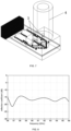
- FIGS. 5 to 7 show the port reflection, gain curve and transmission response of the dual circularly polarized bidirectional data transmission module, and the result shows that the 1 dB bandwidth of module transmission reaches 5GHz, and the 3dB bandwidth thereof exceeds 6.5GHz.
- a pair of dual circularly polarized bidirectional data transmission modules are arranged on the base board and the main control board of the rotating display apparatus according to the present disclosure, such that high-speed digital signals may be bidirectionally transmitted between the base board and the main control board, thus improving the display effect of the rotating display apparatus, and achieving more stable transmission and display effects.
- the dual circularly polarized bidirectional data transmission modules may pass through the motor, thus reducing the volume of the rotating display apparatus.
Landscapes
- Engineering & Computer Science (AREA)
- Physics & Mathematics (AREA)
- Computer Hardware Design (AREA)
- General Physics & Mathematics (AREA)
- Theoretical Computer Science (AREA)
- Computer Networks & Wireless Communication (AREA)
- Signal Processing (AREA)
- Waveguide Connection Structure (AREA)
Claims (15)
- Rotierende Anzeigeeinrichtung basierend auf doppelten zirkular polarisierten bidirektionalen Datenübertragungsmodulen, umfassend eine Grundplatte (20), einen Motor (21), eine Hauptsteuerplatte (22) und eine LED-Lichtplatte (23), wobei ein Paar von doppelten zirkular polarisierten bidirektionalen Datenübertragungsmodulen (10, 11) auf der Grundplatte (20) und der Hauptsteuerplatte (22) eingerichtet ist und jedes der doppelten zirkular polarisierten bidirektionalen Datenübertragungsmodule (10, 11) einen Millimeterwellen-Modulations-Demodulations-Transceiver (1), eine elektrische 90 Grad-Brücke mit in einem Substrat integrierten Wellenleiter (2), Anregungslücken mit orthogonalem Halbmodenwellenleiter (3) und einen zirkular polarisierten Radiator mit kombiniertem Wellenleiter mit orthogonaler Mode (4) umfasst; und
die elektrische 90 Grad-Brücke mit in einem Substrat integrierten Wellenleiter (2) mit dem Millimeterwellen-Modulations-Demodulations-Transceiver (1) verbunden ist, die Anregungslücken mit orthogonalem Halbmodenwellenleiter (3) mit der elektrischen 90 Grad-Brücke mit in einem Substrat integrierten Wellenleiter (2) verbunden sind und der zirkular polarisierte Radiator mit kombiniertem Wellenleiter mit orthogonaler Mode (4) mit den Anregungslücken mit orthogonalem Halbmodenwellenleiter (3) verbunden ist. - Rotierende Anzeigeeinrichtung basierend auf doppelten zirkular polarisierten bidirektionalen Datenübertragungsmodulen nach Anspruch 1, wobei der Millimeterwellen-Modulations-Demodulations-Transceiver (1) eine Übertragungsschaltung und eine Empfangsschaltung umfasst;die Übertragungsschaltung konfiguriert ist, um ein digitales Hochgeschwindigkeitsbasisbandsignal in ein digitales Millimeterwellensignal zu modulieren und das digitale Millimeterwellensignal an die elektrische 90 Grad-Brücke mit in einem Substrat integrierten Wellenleiter (2) zu übertragen; unddie Empfangsschaltung konfiguriert ist, um ein digitales Millimeterwellensignal, das von der elektrischen 90 Grad-Brücke mit in einem Substrat integrierten Wellenleiter (2) ausgegeben wird, zu empfangen und das digitale Millimeterwellensignal in ein digitales Hochgeschwindigkeitsbasisbandsignal zu demodulieren.
- Rotierende Anzeigeeinrichtung basierend auf doppelten zirkular polarisierten bidirektionalen Datenübertragungsmodulen nach Anspruch 2, wobei die Übertragungsschaltung konfiguriert ist, um mittels ASK-Modulation eine Frequenzmischverarbeitung am eingegebenen digitalen Hochgeschwindigkeitsbasisbandsignal durchzuführen, um das digitale Signal auf einen Millimeterwellenträger zu modulieren und das digitale Millimeterwellensignal zu erhalten.
- Rotierende Anzeigeeinrichtung basierend auf doppelten zirkular polarisierten bidirektionalen Datenübertragungsmodulen nach Anspruch 3, wobei die Übertragungsschaltung konfiguriert ist, um ein eingegebenes differentielles Hochgeschwindigkeitsbasisbandsignal mit einer Übertragungsrate von 0-5 Gbps zu empfangen.
- Rotierende Anzeigeeinrichtung basierend auf doppelten zirkular polarisierten bidirektionalen Datenübertragungsmodulen nach Anspruch 2, wobei die Empfangsschaltung konfiguriert ist, um eine Demodulierungsverarbeitung am empfangenen digitalen Millimetermodulationssignal durch Erfassung und Vergleich einer inkohärenten Hülle durchzuführen, um das digitale Hochgeschwindigkeitsbasisbandsignal zu erhalten.
- Rotierende Anzeigeeinrichtung basierend auf doppelten zirkular polarisierten bidirektionalen Datenübertragungsmodulen nach einem der Ansprüche 1 bis 5, wobei das Paar von doppelten zirkular polarisierten bidirektionalen Datenübertragungsmodulen (10, 11) zwei doppelte zirkular polarisierte bidirektionale Datenübertragungsmodule (10, 11) umfasst und die zwei doppelten zirkular polarisierten bidirektionalen Datenübertragungsmodule (10, 11) auf der Grundplatte (20) bzw. der Hauptsteuerplatte (20) eingerichtet sind.
- Rotierende Anzeigeeinrichtung basierend auf doppelten zirkular polarisierten bidirektionalen Datenübertragungsmodulen nach Anspruch 6, wobei die zwei doppelten zirkular polarisierten bidirektionalen Datenübertragungsmodule (10, 11) eine gleiche Struktur aufweisen.
- Rotierende Anzeigeeinrichtung basierend auf doppelten zirkular polarisierten bidirektionalen Datenübertragungsmodulen nach Anspruch 6, wobei die elektrische 90 Grad-Brücke mit in einem Substrat integrierten Wellenleiter (2), die im doppelten zirkular polarisierten bidirektionalen Datenübertragungsmodul (10) auf der Grundplatte (20) umfasst ist, auf der Grundlage eines Leiterplattenprozesses auf der Grundplatte (20) integriert ist; und
die elektrische 90 Grad-Brücke mit in einem Substrat integrierten Wellenleiter (2), die im doppelten zirkular polarisierten bidirektionalen Datenübertragungsmodul (11) auf der Hauptsteuerplatte (22) umfasst ist, auf der Grundlage eines Leiterplattenprozesses auf der Hauptsteuerplatte (22) integriert ist. - Rotierende Anzeigeeinrichtung basierend auf doppelten zirkular polarisierten bidirektionalen Datenübertragungsmodulen nach einem der Ansprüche 1 bis 8, wobei die elektrische 90 Grad-Brücke mit in einem Substrat integrierten Wellenleiter (2) eine obere und untere Metallschicht (8), eine dielektrische Hochfrequenzplatte (5) und metallisierte Durchgangslöcher (6) umfasst, wobei die obere und untere Metallschicht (8) beide Seiten der dielektrischen Hochfrequenzplatte (5) abdeckt und die metallisierten Durchgangslöcher (6) in einer von der oberen und unteren Metallschicht (8) und der dielektrischen Hochfrequenzplatte (5) gebildeten Gesamtheit bereitgestellt sind.
- Rotierende Anzeigeeinrichtung basierend auf doppelten zirkular polarisierten bidirektionalen Datenübertragungsmodulen nach einem der Ansprüche 1 bis 9, wobei zwei Anschlüsse der elektrischen 90 Grad-Brücke mit in einem Substrat integrierten Wellenleiter (2) durch Mikrostreifenübertragungsleitungen (7) mit dem Millimeterwellen-Modulations-Demodulations-Transceiver (1) verbunden sind.
- Rotierende Anzeigeeinrichtung basierend auf doppelten zirkular polarisierten bidirektionalen Datenübertragungsmodulen nach einem der Ansprüche 1 bis 10, wobei offene schmale Spalten (9) an einem Ende der elektrischen 90 Grad-Brücke mit in einem Substrat integrierten Wellenleiter (2) bereitgestellt sind und die offenen schmalen Spalten (9) einen eingeschlossenen Winkel von 90 Grad aufweisen.
- Rotierende Anzeigeeinrichtung basierend auf doppelten zirkular polarisierten bidirektionalen Datenübertragungsmodulen nach einem der Ansprüche 1 bis 11, wobei die Anregungslücken mit orthogonalem Halbmodenwellenleiter (3) und der zirkular polarisierte Radiator mit kombiniertem Wellenleiter mit orthogonaler Mode (4) eine einstückige Metallstruktur bilden und die Metallstruktur oberhalb der elektrischen 90 Grad-Brücke mit in einem Substrat integrierten Wellenleiter (2) befestigt ist.
- Rotierende Anzeigeeinrichtung basierend auf doppelten zirkular polarisierten bidirektionalen Datenübertragungsmodulen nach einem der Ansprüche 1 bis 11, wobei die Anregungslücken mit orthogonalem Halbmodenwellenleiter (3) und der zirkular polarisierte Radiator mit kombiniertem Wellenleiter mit orthogonaler Mode (4) eine einstückige Metallstruktur bilden und die Metallstruktur auf einer Leiterplatte gepresst wird, wo sich die elektrische 90 Grad-Brücke mit in einem Substrat integrierten Wellenleiter (2) befindet.
- Rotierende Anzeigeeinrichtung basierend auf doppelten zirkular polarisierten bidirektionalen Datenübertragungsmodulen nach einem der Ansprüche 1 bis 13, wobei sich der zirkular polarisierte Radiator mit kombiniertem Wellenleiter mit orthogonaler Mode (4) an einem Drehmittelpunkt der rotierenden Anzeigeeinrichtung befindet.
- Rotierende Anzeigeeinrichtung basierend auf doppelten zirkular polarisierten bidirektionalen Datenübertragungsmodulen nach einem der Ansprüche 1 bis 14, wobei Durchgangslöcher im Motor (21) bereitgestellt sind und das Paar von doppelten zirkular polarisierten bidirektionalen Datenübertragungsmodulen (10, 11) über die Durchgangslöcher durch den Motor (21) gelangen.
Applications Claiming Priority (2)
| Application Number | Priority Date | Filing Date | Title |
|---|---|---|---|
| CN202010279701.9A CN111276078B (zh) | 2020-04-10 | 2020-04-10 | 一种基于双圆极化双向数传模块的旋转显示装置 |
| PCT/CN2020/115995 WO2021203627A1 (zh) | 2020-04-10 | 2020-09-17 | 一种基于双圆极化双向数传模块的旋转显示装置 |
Publications (4)
| Publication Number | Publication Date |
|---|---|
| EP4134937A1 EP4134937A1 (de) | 2023-02-15 |
| EP4134937A4 EP4134937A4 (de) | 2023-10-04 |
| EP4134937B1 true EP4134937B1 (de) | 2024-02-21 |
| EP4134937C0 EP4134937C0 (de) | 2024-02-21 |
Family
ID=71000997
Family Applications (1)
| Application Number | Title | Priority Date | Filing Date |
|---|---|---|---|
| EP20929839.7A Active EP4134937B1 (de) | 2020-04-10 | 2020-09-17 | Rotierende anzeigevorrichtung auf basis von doppelten zirkular polarisierten bidirektionalen datenübertragungsmodulen |
Country Status (3)
| Country | Link |
|---|---|
| EP (1) | EP4134937B1 (de) |
| CN (1) | CN111276078B (de) |
| WO (1) | WO2021203627A1 (de) |
Families Citing this family (3)
| Publication number | Priority date | Publication date | Assignee | Title |
|---|---|---|---|---|
| CN111276815B (zh) * | 2020-04-10 | 2025-03-25 | 南京达斯琪数字科技有限公司 | 一种毫米波双圆极化双向数传模块及装置 |
| CN111276078B (zh) * | 2020-04-10 | 2024-11-15 | 南京达斯琪数字科技有限公司 | 一种基于双圆极化双向数传模块的旋转显示装置 |
| CN112864593B (zh) * | 2020-12-31 | 2022-03-29 | 华南理工大学 | 基于3d打印技术的宽带开口波导结构双圆极化天线 |
Family Cites Families (29)
| Publication number | Priority date | Publication date | Assignee | Title |
|---|---|---|---|---|
| JPS63139406A (ja) * | 1986-12-01 | 1988-06-11 | Nec Corp | 円偏波スロツトアンテナ |
| US6492973B1 (en) * | 1998-09-28 | 2002-12-10 | Sharp Kabushiki Kaisha | Method of driving a flat display capable of wireless connection and device for driving the same |
| JP2000172216A (ja) * | 1998-09-28 | 2000-06-23 | Sharp Corp | ディスプレイの駆動方法および駆動装置 |
| RU2251768C2 (ru) * | 2002-12-20 | 2005-05-10 | Общество с ограниченной ответственностью Научно-производственное предприятие "Агама" | Микрополосковая антенна круговой поляризации |
| GB0419071D0 (en) * | 2004-08-26 | 2004-09-29 | Mgx Internat Ltd | Display device |
| JP2010103982A (ja) * | 2008-09-25 | 2010-05-06 | Sony Corp | ミリ波伝送装置、ミリ波伝送方法、ミリ波伝送システム |
| CN102224728B (zh) * | 2008-11-17 | 2013-11-06 | 日本电气株式会社 | 通信系统和接收机 |
| US8144066B2 (en) * | 2009-02-26 | 2012-03-27 | Harris Corporation | Wireless communications including an antenna for wireless power transmission and data communication and associated methods |
| US9559405B2 (en) * | 2009-06-12 | 2017-01-31 | Qualcomm Incorporated | Devices and methods related to a display assembly including an antenna |
| FR2956252B1 (fr) * | 2010-02-05 | 2013-04-26 | Thales Sa | Antenne plane directive embarquee, vehicule comportant une telle antenne et systeme de telecommunication par satellite comportant un tel vehicule |
| CN103022730A (zh) * | 2012-12-27 | 2013-04-03 | 北京理工大学 | 一种高增益多层介质复合双圆极化微带阵列天线 |
| CN103247858A (zh) * | 2013-04-26 | 2013-08-14 | 清华大学 | 具有双向同旋、双圆极化波辐射特性的金属波导天线 |
| US9823625B2 (en) * | 2014-03-18 | 2017-11-21 | Casio Computer Co., Ltd. | Electronic device |
| CN104600425B (zh) * | 2015-02-12 | 2018-05-08 | 东南大学 | 一种宽带高增益双圆极化贴片天线 |
| CN205176504U (zh) * | 2015-09-30 | 2016-04-20 | 胡三明 | 一种集led照明、通信、无线充电及定位于一体的家电装置 |
| CN105914465A (zh) * | 2016-04-15 | 2016-08-31 | 上海安费诺永亿通讯电子有限公司 | 圆极化天线及其无线通信设备 |
| CN106016155A (zh) * | 2016-06-02 | 2016-10-12 | 斯琴 | 智能led灯 |
| CN106684540A (zh) * | 2016-08-03 | 2017-05-17 | 北京航天长征飞行器研究所 | 一种防静电的双圆极化有源微带天线 |
| CN107979734B (zh) * | 2016-10-25 | 2020-09-04 | 巽晨国际股份有限公司 | 能以毫米波且360度传输影像的图像处理系统 |
| CN107394395B (zh) * | 2017-07-07 | 2020-10-27 | 东南大学 | 基于平面正交模耦合器的双极化喇叭天线 |
| CN109143376B (zh) * | 2018-08-13 | 2020-03-27 | 浙江大学 | 一种全景电磁光学融合成像系统和方法 |
| CN209119368U (zh) * | 2018-12-20 | 2019-07-16 | 北京星英联微波科技有限责任公司 | 微波与毫米波超宽带多模极化快速切换天线 |
| CN109888475A (zh) * | 2019-02-26 | 2019-06-14 | 重庆邮电大学 | 一种毫米波双频双圆极化基片集成波导天线 |
| CN209526203U (zh) * | 2019-03-18 | 2019-10-22 | 珠海微度芯创科技有限责任公司 | 宽频带双圆极化微带转波导馈源天线系统 |
| CN110021816B (zh) * | 2019-03-18 | 2024-12-06 | 珠海微度芯创科技有限责任公司 | 宽频带双圆极化微带转波导馈源天线系统 |
| CN210270929U (zh) * | 2019-09-27 | 2020-04-07 | 南京达斯琪数字科技有限公司 | 一种基于人脸识别的显示系统 |
| CN111276078B (zh) * | 2020-04-10 | 2024-11-15 | 南京达斯琪数字科技有限公司 | 一种基于双圆极化双向数传模块的旋转显示装置 |
| CN211507076U (zh) * | 2020-04-10 | 2020-09-15 | 南京达斯琪数字科技有限公司 | 一种基于双圆极化双向数传模块的旋转显示装置 |
| CN111276815B (zh) * | 2020-04-10 | 2025-03-25 | 南京达斯琪数字科技有限公司 | 一种毫米波双圆极化双向数传模块及装置 |
-
2020
- 2020-04-10 CN CN202010279701.9A patent/CN111276078B/zh active Active
- 2020-09-17 EP EP20929839.7A patent/EP4134937B1/de active Active
- 2020-09-17 WO PCT/CN2020/115995 patent/WO2021203627A1/zh not_active Ceased
Also Published As
| Publication number | Publication date |
|---|---|
| EP4134937A1 (de) | 2023-02-15 |
| EP4134937C0 (de) | 2024-02-21 |
| CN111276078B (zh) | 2024-11-15 |
| WO2021203627A1 (zh) | 2021-10-14 |
| CN111276078A (zh) | 2020-06-12 |
| EP4134937A4 (de) | 2023-10-04 |
Similar Documents
| Publication | Publication Date | Title |
|---|---|---|
| US5124713A (en) | Planar microwave antenna for producing circular polarization from a patch radiator | |
| EP4134937A1 (de) | Rotierende anzeigevorrichtung auf basis von doppelten zirkular polarisierten bidirektionalen datenübertragungsmodulen | |
| CN101471711B (zh) | 具有波束调向和/或成形天线的数据处理装置 | |
| US6459415B1 (en) | Omni-directional planar antenna design | |
| US6304220B1 (en) | Antenna with stacked resonant structures and a multi-frequency radiocommunications system including it | |
| CN111276815B (zh) | 一种毫米波双圆极化双向数传模块及装置 | |
| US4827266A (en) | Antenna with lumped reactive matching elements between radiator and groundplate | |
| JPS6354023A (ja) | マイクロ波信号の受信機構体 | |
| EP4266502B1 (de) | Antennenstruktur, elektronische vorrichtung und drahtloses netzwerksystem | |
| US11784418B2 (en) | Multi-directional dual-polarized antenna system | |
| US20240113448A1 (en) | Quad 5g nr mimo antenna array with slanted formation | |
| EP4293824B1 (de) | Antennenanordnung und fahrzeug | |
| CN211743401U (zh) | 一种毫米波双圆极化双向数传模块及装置 | |
| US20250096481A1 (en) | Transmission device and antenna | |
| CN211507076U (zh) | 一种基于双圆极化双向数传模块的旋转显示装置 | |
| CN215869784U (zh) | 一种车载多频段多端口的mimo天线 | |
| EP3832800B1 (de) | Antennenvorrichtung und kommunikationsvorrichtung | |
| CN112968272B (zh) | 一种宽带宽波束低剖面圆极化天线 | |
| CN214203968U (zh) | 一种Ka波段中心馈电的旋转阵列天线 | |
| CN209981457U (zh) | 组合天线及终端设备 | |
| JP3181326B2 (ja) | マイクロストリツプアンテナ、およびアレーアンテナ | |
| CN210296620U (zh) | 一种宽带双圆极化贴片天线 | |
| JPH07162227A (ja) | 偏波共用アンテナシステム | |
| CN110265776A (zh) | 一种宽带双圆极化贴片天线 | |
| JPH11261330A (ja) | 非接触icカードアンテナ |
Legal Events
| Date | Code | Title | Description |
|---|---|---|---|
| STAA | Information on the status of an ep patent application or granted ep patent |
Free format text: STATUS: THE INTERNATIONAL PUBLICATION HAS BEEN MADE |
|
| PUAI | Public reference made under article 153(3) epc to a published international application that has entered the european phase |
Free format text: ORIGINAL CODE: 0009012 |
|
| STAA | Information on the status of an ep patent application or granted ep patent |
Free format text: STATUS: REQUEST FOR EXAMINATION WAS MADE |
|
| 17P | Request for examination filed |
Effective date: 20221108 |
|
| AK | Designated contracting states |
Kind code of ref document: A1 Designated state(s): AL AT BE BG CH CY CZ DE DK EE ES FI FR GB GR HR HU IE IS IT LI LT LU LV MC MK MT NL NO PL PT RO RS SE SI SK SM TR |
|
| DAV | Request for validation of the european patent (deleted) | ||
| DAX | Request for extension of the european patent (deleted) | ||
| A4 | Supplementary search report drawn up and despatched |
Effective date: 20230901 |
|
| RIC1 | Information provided on ipc code assigned before grant |
Ipc: B44F 7/00 20060101ALI20230828BHEP Ipc: H04B 1/38 20150101ALI20230828BHEP Ipc: G09G 3/00 20060101AFI20230828BHEP |
|
| GRAP | Despatch of communication of intention to grant a patent |
Free format text: ORIGINAL CODE: EPIDOSNIGR1 |
|
| STAA | Information on the status of an ep patent application or granted ep patent |
Free format text: STATUS: GRANT OF PATENT IS INTENDED |
|
| INTG | Intention to grant announced |
Effective date: 20231012 |
|
| GRAS | Grant fee paid |
Free format text: ORIGINAL CODE: EPIDOSNIGR3 |
|
| GRAA | (expected) grant |
Free format text: ORIGINAL CODE: 0009210 |
|
| STAA | Information on the status of an ep patent application or granted ep patent |
Free format text: STATUS: THE PATENT HAS BEEN GRANTED |
|
| AK | Designated contracting states |
Kind code of ref document: B1 Designated state(s): AL AT BE BG CH CY CZ DE DK EE ES FI FR GB GR HR HU IE IS IT LI LT LU LV MC MK MT NL NO PL PT RO RS SE SI SK SM TR |
|
| REG | Reference to a national code |
Ref country code: GB Ref legal event code: FG4D |
|
| REG | Reference to a national code |
Ref country code: CH Ref legal event code: EP |
|
| REG | Reference to a national code |
Ref country code: DE Ref legal event code: R096 Ref document number: 602020026252 Country of ref document: DE |
|
| REG | Reference to a national code |
Ref country code: IE Ref legal event code: FG4D |
|
| U01 | Request for unitary effect filed |
Effective date: 20240320 |
|
| U07 | Unitary effect registered |
Designated state(s): AT BE BG DE DK EE FI FR IT LT LU LV MT NL PT SE SI Effective date: 20240328 |
|
| PG25 | Lapsed in a contracting state [announced via postgrant information from national office to epo] |
Ref country code: IS Free format text: LAPSE BECAUSE OF FAILURE TO SUBMIT A TRANSLATION OF THE DESCRIPTION OR TO PAY THE FEE WITHIN THE PRESCRIBED TIME-LIMIT Effective date: 20240621 |
|
| PG25 | Lapsed in a contracting state [announced via postgrant information from national office to epo] |
Ref country code: GR Free format text: LAPSE BECAUSE OF FAILURE TO SUBMIT A TRANSLATION OF THE DESCRIPTION OR TO PAY THE FEE WITHIN THE PRESCRIBED TIME-LIMIT Effective date: 20240522 |
|
| PG25 | Lapsed in a contracting state [announced via postgrant information from national office to epo] |
Ref country code: HR Free format text: LAPSE BECAUSE OF FAILURE TO SUBMIT A TRANSLATION OF THE DESCRIPTION OR TO PAY THE FEE WITHIN THE PRESCRIBED TIME-LIMIT Effective date: 20240221 Ref country code: RS Free format text: LAPSE BECAUSE OF FAILURE TO SUBMIT A TRANSLATION OF THE DESCRIPTION OR TO PAY THE FEE WITHIN THE PRESCRIBED TIME-LIMIT Effective date: 20240521 |
|
| PG25 | Lapsed in a contracting state [announced via postgrant information from national office to epo] |
Ref country code: ES Free format text: LAPSE BECAUSE OF FAILURE TO SUBMIT A TRANSLATION OF THE DESCRIPTION OR TO PAY THE FEE WITHIN THE PRESCRIBED TIME-LIMIT Effective date: 20240221 |
|
| PG25 | Lapsed in a contracting state [announced via postgrant information from national office to epo] |
Ref country code: RS Free format text: LAPSE BECAUSE OF FAILURE TO SUBMIT A TRANSLATION OF THE DESCRIPTION OR TO PAY THE FEE WITHIN THE PRESCRIBED TIME-LIMIT Effective date: 20240521 Ref country code: NO Free format text: LAPSE BECAUSE OF FAILURE TO SUBMIT A TRANSLATION OF THE DESCRIPTION OR TO PAY THE FEE WITHIN THE PRESCRIBED TIME-LIMIT Effective date: 20240521 Ref country code: IS Free format text: LAPSE BECAUSE OF FAILURE TO SUBMIT A TRANSLATION OF THE DESCRIPTION OR TO PAY THE FEE WITHIN THE PRESCRIBED TIME-LIMIT Effective date: 20240621 Ref country code: HR Free format text: LAPSE BECAUSE OF FAILURE TO SUBMIT A TRANSLATION OF THE DESCRIPTION OR TO PAY THE FEE WITHIN THE PRESCRIBED TIME-LIMIT Effective date: 20240221 Ref country code: GR Free format text: LAPSE BECAUSE OF FAILURE TO SUBMIT A TRANSLATION OF THE DESCRIPTION OR TO PAY THE FEE WITHIN THE PRESCRIBED TIME-LIMIT Effective date: 20240522 Ref country code: ES Free format text: LAPSE BECAUSE OF FAILURE TO SUBMIT A TRANSLATION OF THE DESCRIPTION OR TO PAY THE FEE WITHIN THE PRESCRIBED TIME-LIMIT Effective date: 20240221 |
|
| PG25 | Lapsed in a contracting state [announced via postgrant information from national office to epo] |
Ref country code: PL Free format text: LAPSE BECAUSE OF FAILURE TO SUBMIT A TRANSLATION OF THE DESCRIPTION OR TO PAY THE FEE WITHIN THE PRESCRIBED TIME-LIMIT Effective date: 20240221 |
|
| PG25 | Lapsed in a contracting state [announced via postgrant information from national office to epo] |
Ref country code: PL Free format text: LAPSE BECAUSE OF FAILURE TO SUBMIT A TRANSLATION OF THE DESCRIPTION OR TO PAY THE FEE WITHIN THE PRESCRIBED TIME-LIMIT Effective date: 20240221 |
|
| PG25 | Lapsed in a contracting state [announced via postgrant information from national office to epo] |
Ref country code: SM Free format text: LAPSE BECAUSE OF FAILURE TO SUBMIT A TRANSLATION OF THE DESCRIPTION OR TO PAY THE FEE WITHIN THE PRESCRIBED TIME-LIMIT Effective date: 20240221 |
|
| PG25 | Lapsed in a contracting state [announced via postgrant information from national office to epo] |
Ref country code: CZ Free format text: LAPSE BECAUSE OF FAILURE TO SUBMIT A TRANSLATION OF THE DESCRIPTION OR TO PAY THE FEE WITHIN THE PRESCRIBED TIME-LIMIT Effective date: 20240221 |
|
| PG25 | Lapsed in a contracting state [announced via postgrant information from national office to epo] |
Ref country code: SK Free format text: LAPSE BECAUSE OF FAILURE TO SUBMIT A TRANSLATION OF THE DESCRIPTION OR TO PAY THE FEE WITHIN THE PRESCRIBED TIME-LIMIT Effective date: 20240221 |
|
| U20 | Renewal fee for the european patent with unitary effect paid |
Year of fee payment: 5 Effective date: 20240925 |
|
| PG25 | Lapsed in a contracting state [announced via postgrant information from national office to epo] |
Ref country code: SM Free format text: LAPSE BECAUSE OF FAILURE TO SUBMIT A TRANSLATION OF THE DESCRIPTION OR TO PAY THE FEE WITHIN THE PRESCRIBED TIME-LIMIT Effective date: 20240221 Ref country code: SK Free format text: LAPSE BECAUSE OF FAILURE TO SUBMIT A TRANSLATION OF THE DESCRIPTION OR TO PAY THE FEE WITHIN THE PRESCRIBED TIME-LIMIT Effective date: 20240221 Ref country code: RO Free format text: LAPSE BECAUSE OF FAILURE TO SUBMIT A TRANSLATION OF THE DESCRIPTION OR TO PAY THE FEE WITHIN THE PRESCRIBED TIME-LIMIT Effective date: 20240221 Ref country code: CZ Free format text: LAPSE BECAUSE OF FAILURE TO SUBMIT A TRANSLATION OF THE DESCRIPTION OR TO PAY THE FEE WITHIN THE PRESCRIBED TIME-LIMIT Effective date: 20240221 |
|
| REG | Reference to a national code |
Ref country code: DE Ref legal event code: R097 Ref document number: 602020026252 Country of ref document: DE |
|
| PLBE | No opposition filed within time limit |
Free format text: ORIGINAL CODE: 0009261 |
|
| STAA | Information on the status of an ep patent application or granted ep patent |
Free format text: STATUS: NO OPPOSITION FILED WITHIN TIME LIMIT |
|
| 26N | No opposition filed |
Effective date: 20241122 |
|
| PG25 | Lapsed in a contracting state [announced via postgrant information from national office to epo] |
Ref country code: MC Free format text: LAPSE BECAUSE OF FAILURE TO SUBMIT A TRANSLATION OF THE DESCRIPTION OR TO PAY THE FEE WITHIN THE PRESCRIBED TIME-LIMIT Effective date: 20240221 |
|
| REG | Reference to a national code |
Ref country code: CH Ref legal event code: PL |
|
| GBPC | Gb: european patent ceased through non-payment of renewal fee |
Effective date: 20240917 |
|
| PG25 | Lapsed in a contracting state [announced via postgrant information from national office to epo] |
Ref country code: GB Free format text: LAPSE BECAUSE OF NON-PAYMENT OF DUE FEES Effective date: 20240917 |
|
| PG25 | Lapsed in a contracting state [announced via postgrant information from national office to epo] |
Ref country code: CH Free format text: LAPSE BECAUSE OF NON-PAYMENT OF DUE FEES Effective date: 20240930 |
|
| PG25 | Lapsed in a contracting state [announced via postgrant information from national office to epo] |
Ref country code: IE Free format text: LAPSE BECAUSE OF NON-PAYMENT OF DUE FEES Effective date: 20240917 |
|
| U20 | Renewal fee for the european patent with unitary effect paid |
Year of fee payment: 6 Effective date: 20250923 |
|
| PG25 | Lapsed in a contracting state [announced via postgrant information from national office to epo] |
Ref country code: CY Free format text: LAPSE BECAUSE OF FAILURE TO SUBMIT A TRANSLATION OF THE DESCRIPTION OR TO PAY THE FEE WITHIN THE PRESCRIBED TIME-LIMIT; INVALID AB INITIO Effective date: 20200917 |
|
| PG25 | Lapsed in a contracting state [announced via postgrant information from national office to epo] |
Ref country code: HU Free format text: LAPSE BECAUSE OF FAILURE TO SUBMIT A TRANSLATION OF THE DESCRIPTION OR TO PAY THE FEE WITHIN THE PRESCRIBED TIME-LIMIT; INVALID AB INITIO Effective date: 20200917 |